

MOTO GUZZI 850-T Owner's Manual
850 - T
OWNER'S
MANUAL
Pt # 1790 0000

Dear rider,
First of
all
we
wish to thank you for choosing this motorcycle of our
preduction.
By
following the instructions outlined
in
this manual you will ensure
your bike
s long
and
troublefree life .
Before riding, please read thoroughly this
manual in order
to
know your
motorcycle's feafures and
how
to
operate it safely.
All
major checking
and
overhaul jobs are best carried out by our dea-
lers who have the necessary
fa
cilities
to
quic/ely
and competently repair
your Mota Guzzi.
Repairs
or
adjus tments
by
other than a Guzzi dealer during the warranty
period
could
invalidate the warranty right .
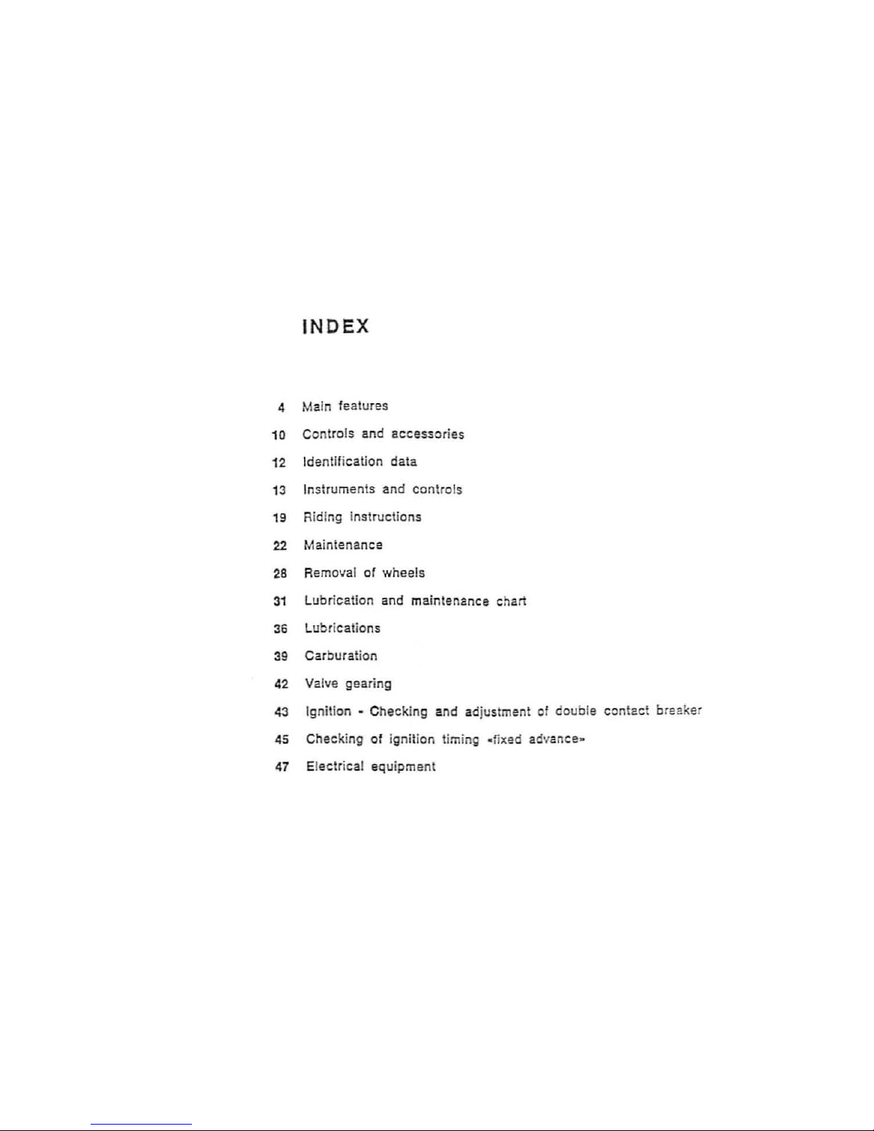
INDEX
4 Main features
10 Controls and accessories
12
Identification deta
13
Instruments and controls
19
Riding instructions
22
Maintenance
28
Removal or wheels
31
Lubrication and maintenance chart
36
Lubr ications
39
Carburation
42
Valve
gear
ing
43
Ignition - Checking and adjustment of double con tact breaker
45
Checking of ignition timing
..
fixed ad'/ance
..
47 Electrical equipment
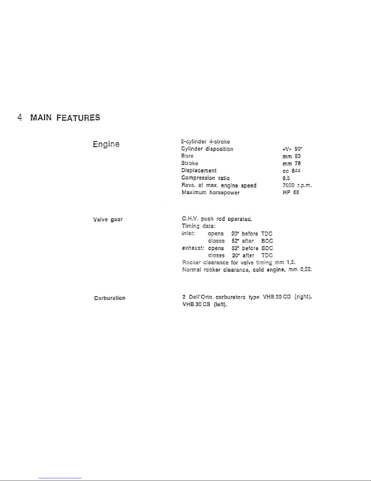
4
MAIN
FEATURES
Engine
Valve gear
C
arburali
on
2-cylinder 4·stroke
C
ylinder ciispositio n
Bore
Stroke
Displacemen
t
Compression
ra tio
Revs. at max. engine
speed
Maximum
horsepower
O.H.V. push rod operated.
T
iming
data:
inlet: opens
20"'
before TOe
closes 52' aHer BOC
exhaust:
opens
52*
before
SOC
clos
es
20- after TOe
.v
..
9
0"
mm
83
mm 78
cc 844
9,5
7000 r.p .
m.
H?
65
Rec ker clearance
for
valve timing mm 1.
:.
Nor
mal
rocker
clearance, ce
ld
engine, mm 0,22.
2
Oell'Orto
carburetors
type VHB 30 CD (right).
VHB
30 CS (left).
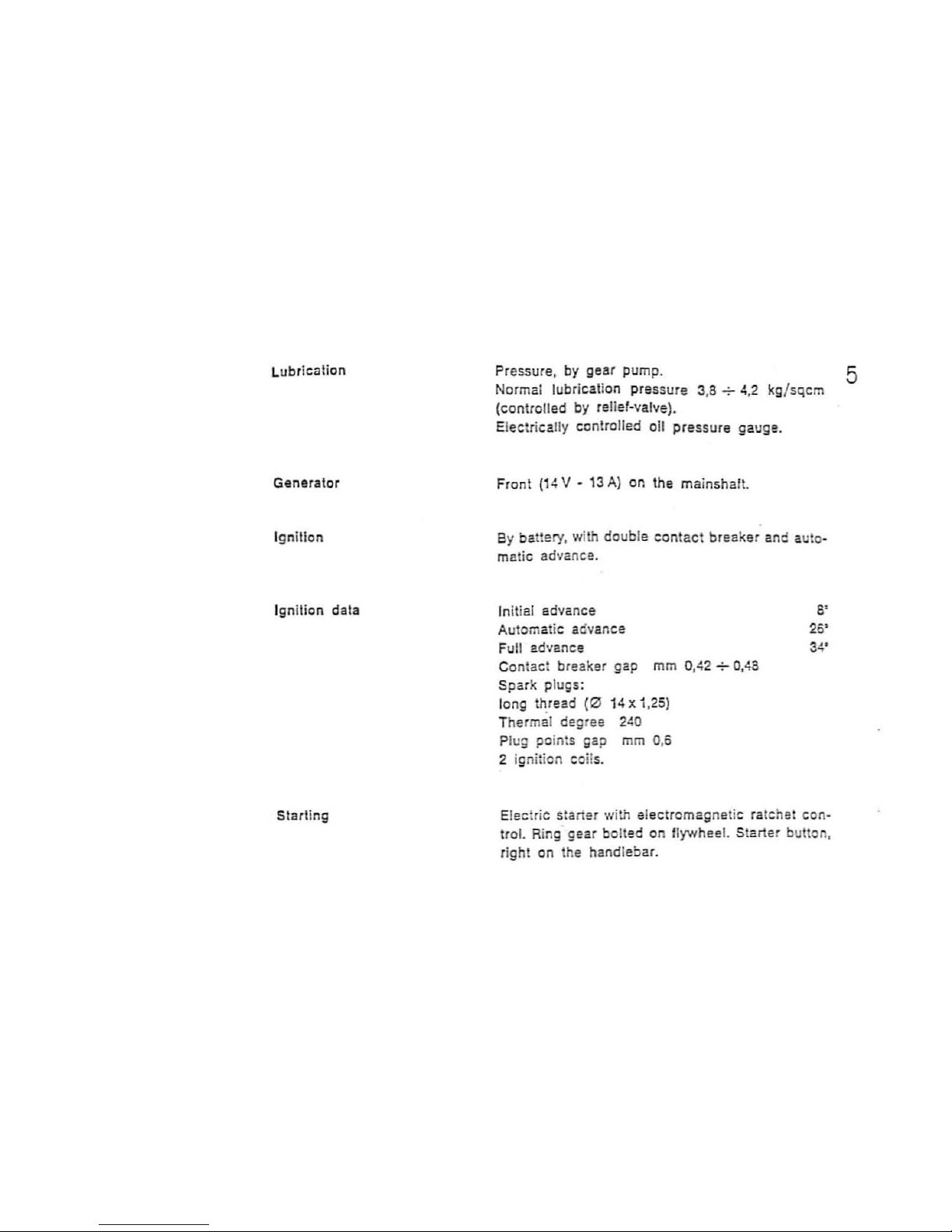
Lubr
icati
on
Ge
nerat
or
Ignillon
Ignition data
Starting
Pressure, by
gear
pump.
Normal lubrication pressure 3,
8";-
4,2 kg/sqcm
(controlled by reli
ef-valve).
El
ectr
ica
lly
controlled o
il
pressure gau ge.
Front
(14
V - 13
A)
on the mainshaft.
By battery, with double
contact
breaker and auto-
matic advance.
In
iti
el advance
Automatic advance
Fu
ll
advance
Contac t
breakS'r gap mm 0,42 +
0,48
Spark plugs:
long thread
(0
14
x 1,25)
Thermal
degree
240
Plug points gap mm 0,6
2 ignition coil
s.
S'
26'
Electric starter with el
ectromagnet
ic ratchet
con
·
trol.
Ring gear bolted on flywheel. Starter button.
ri
ght
on the handlebar.
5
6
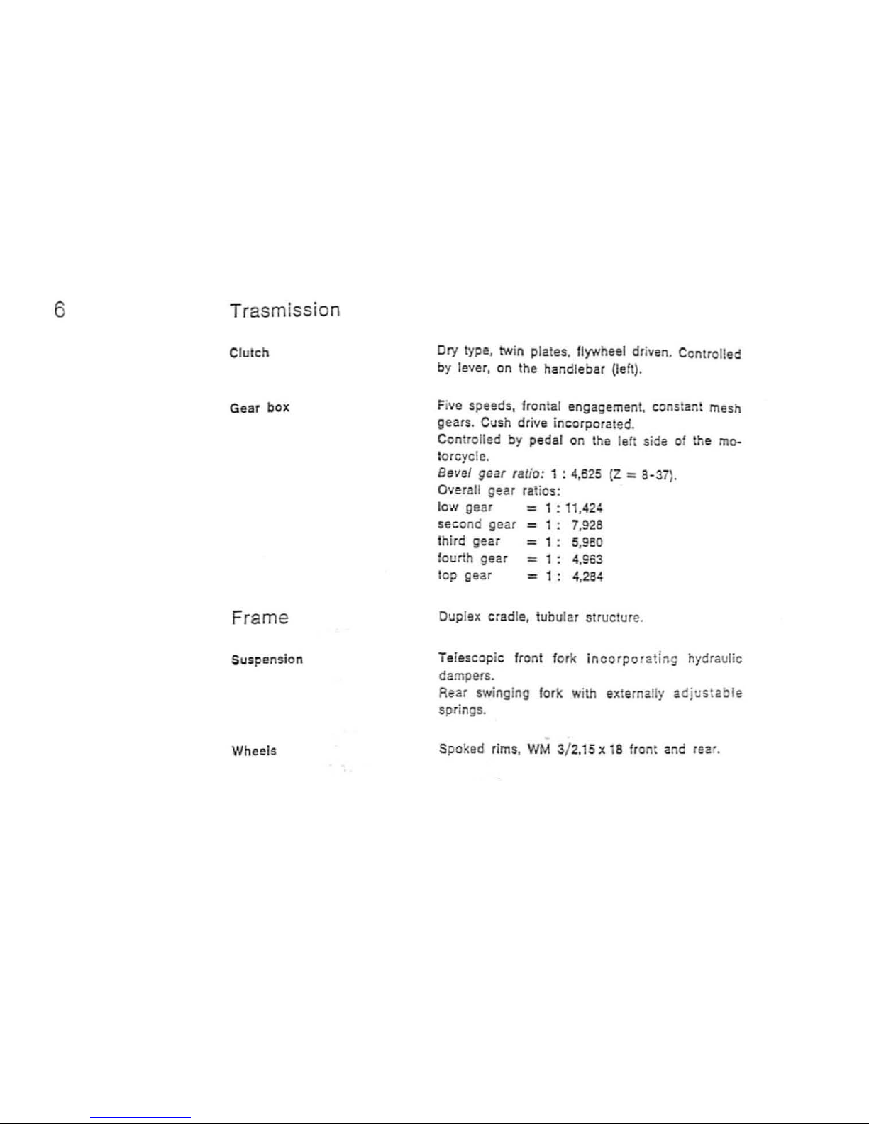
Trasm ission
CIU
ICh
Gear
box
Frame
Suspen
sio
n
Wheels
Dry type, twin plates. flywheel driven . Controlled
by lever, on the handlebar (left).
Fi
ve
speeds, frontal engagement. constant mesh
gears. Cush drive incorporated.
Controlled
by
pedal on the left side of the mo-
torcycle.
Bevel gear ,a/io: 1 : 4,625
(Z
= 8-37
).
Overall
gear
ratios:
low
gear
= 1 :
11.424
second
gear = 1:
7,928
third
gear
=
1: 5,9EO
fourth
gear
=
1:
4,963
top gear
:::::
1:
4,284
Duplex crad l
e,
tubular structure.
Telescopic front fork
incorpora
tin~
hydraulic
dampers.
Rear swinging
fork with externally acj
ustab
le
springs.
Spo ked rims ,
WM
3/ 2.15 x 18 front and l
sa
r.
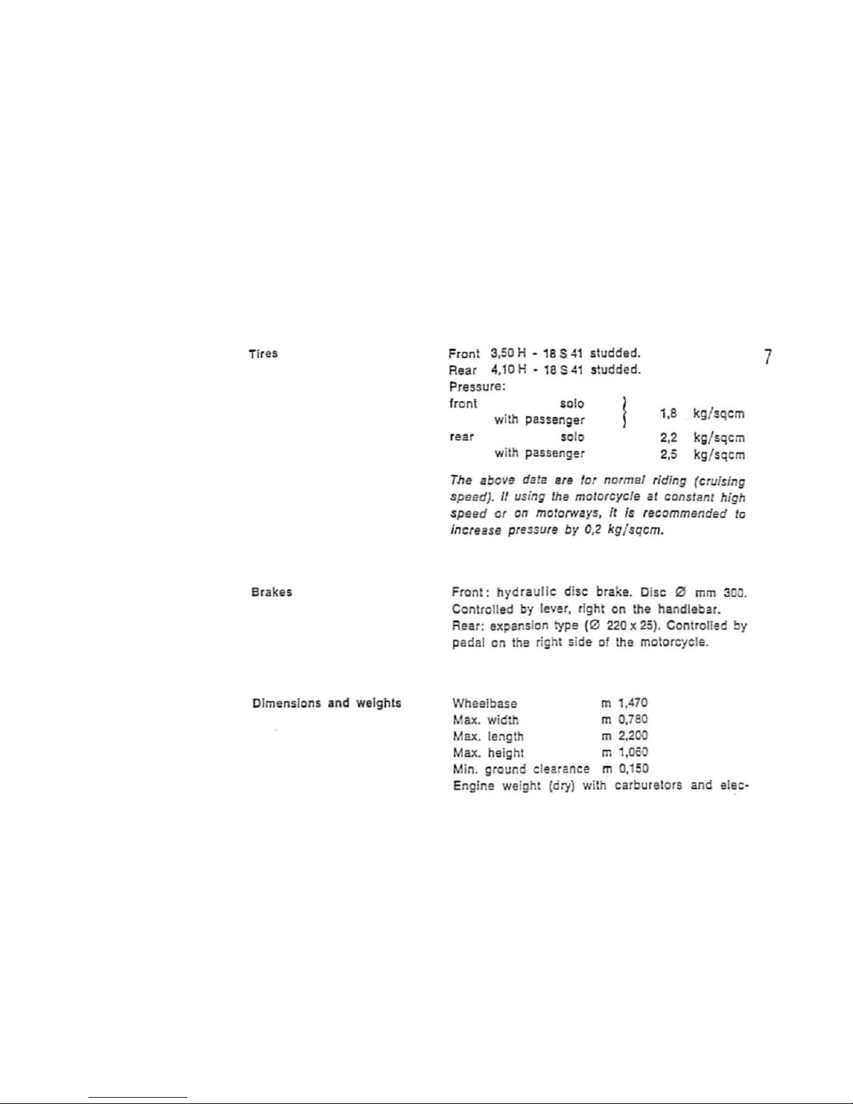
Tires
Brake s
Dimensions
and weights
Front 3,
50
H -
18 S 41
studded.
Rear
4.10 H -
18
S
~1
studded.
Pressure:
front
$010
with
passenger
r
ear
solo
with passenger
1.8
kg
/sqcm
2.2
kg
/sqcm
2
.5
kg
/sqcm
The
abovg data
Bre
for normal
rid
ing (cruising
speed). If us;ng Ihe motorcycle at cons rant h;
gh
speed
or
on
mo/orNays,
It
is recommended
to
increase
pr~ssure
by
0,2
kg/sqcm.
Fro
nl:
hydraulic
di
sc
brake. Disc ~
mm
300.
Controlled
by
lever, right on the handlebar.
Rear: expansion type
(0
220 x
25)
. Controll
ee
by
pedal on the right side of the motorcyc le.
Wheelbase
m
1,470
Max. wi
dth
m 0,780
Max. tength m 2
.200
Max. height m
1,OSO
Min. ground clearance m 0,150
Engine weight (dry) with carburetors and elec-
7
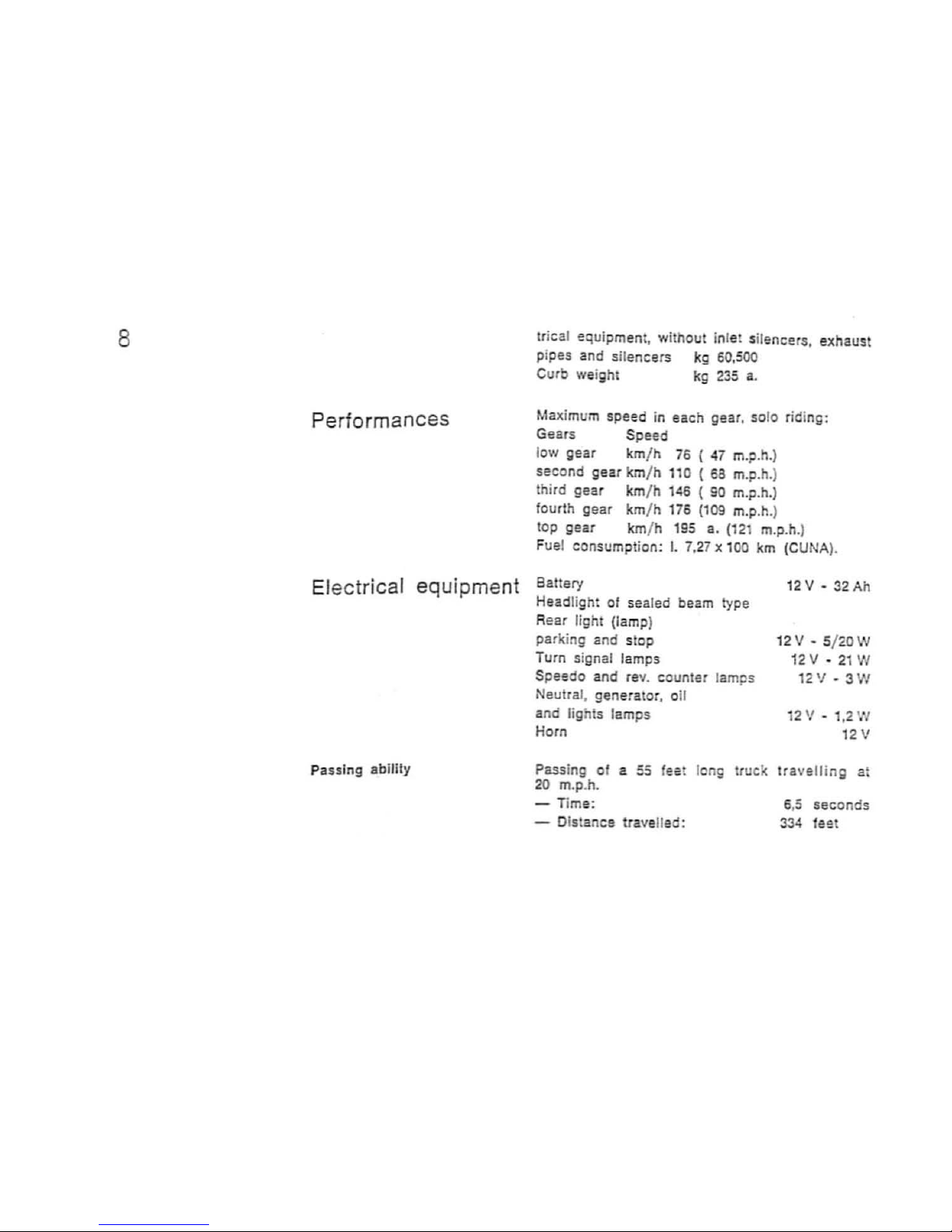
8
Performances
Electrical equipment
Passing ability
tr
ical equipment, without inlet silencers. exhaust
pi
pes
and sil
encers
kg 60,5
00
Cu
rb
weight
kg
235
a.
Maximum speed in eac h gear. 5010 riding:
Gears Spe
ed
1
01'1
gear
km
/ h 76 (
47
m.p.h
.)
second gear km/ h 110 ( 63 m.p.h.)
thi
rd
gear
km
/ h 146 ( 90 m.p.
h.)
fourth gear km/ h
176
(109
m.p.h.)
top gear
km
/ h
195
a. (12 m.p.h
.)
Fuel consumpt ion:
I.
7.27 x 100
km
(CUNA
).
Battery
Headli ght of
sealed
beam type
Rear
light (lamp)
parki
ng
and
slop
Turn signal lamps
Spesdo
and
rev
. counter lam
ps
Neutral, generator, o
il
and lights tamps
Horn
12
V -
32Ah
12V-S/'<OW
12V
- 21 W
12
'1
- 3 W
12
'1
- 1.2 W
12V
Passi
ng
of a 55 fes ! long truck travelling at
20
m.p.h.
- Time:
- Distance
travelled:
6,5
seconds
334 fe2t
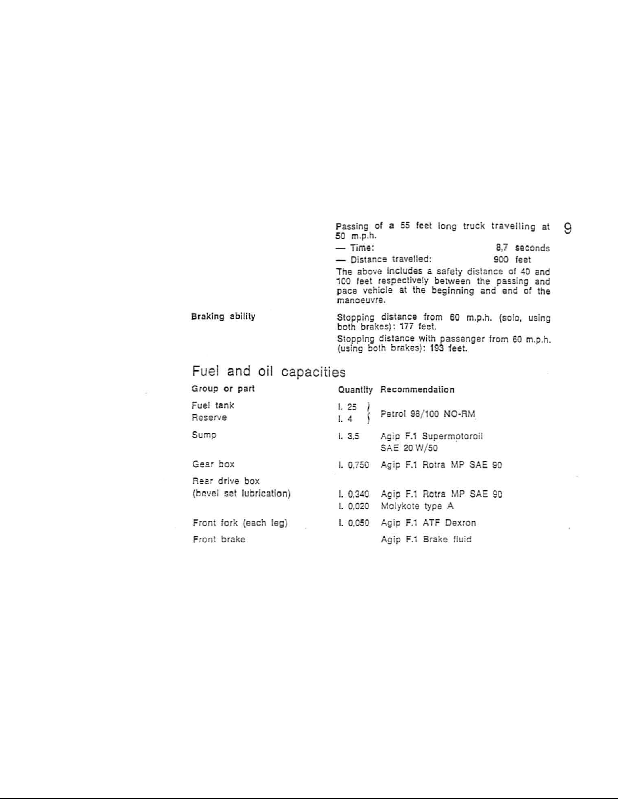
Bra ki ng
ability
Passing of a 55 fee! long
truck
travelling
at 9
50 m.p.h.
- Time:
-
Oistanc~
travelled:
8,7 seconds
900
feet
The above includes a safe
ty
distance of
40
and
1
00
feet respectively between the passing and
pace vehicle at the beginning and end of the
manoeuvre.
Slopping distance from
60
m.p.h.
(solo,
using
both bra kes):
17i
feel.
Stoppi
ng
distance with passenger from
SO
m.p.h.
(us
ing both brakes): 193 1eet.
Fuel and oil capacities
Group
or
part
Fuel tank
Reserve
Sump
Gear box
Rear
dr
ive box
(bevel set lubrication)
Fr
ont fork
(each leg)
Front brake
Quantity Recommendation
I.
25
I.
4
I.
3.5
I.
0,750
I.
0.340
I.
0.02
I.
0.050
Pe
trol 98/
100 NO-AM
Ag
ip F
.1
Supermotoroil
SA: 20 W /50 .
Ag
ip F
.1
Rotta MP SAE S
Ag
ip F
.l
Rotra MP
SA:
90
Molykote type A
Ag
ip F.1 ATF Dexron
Agip
F.1
Brake fluid
10
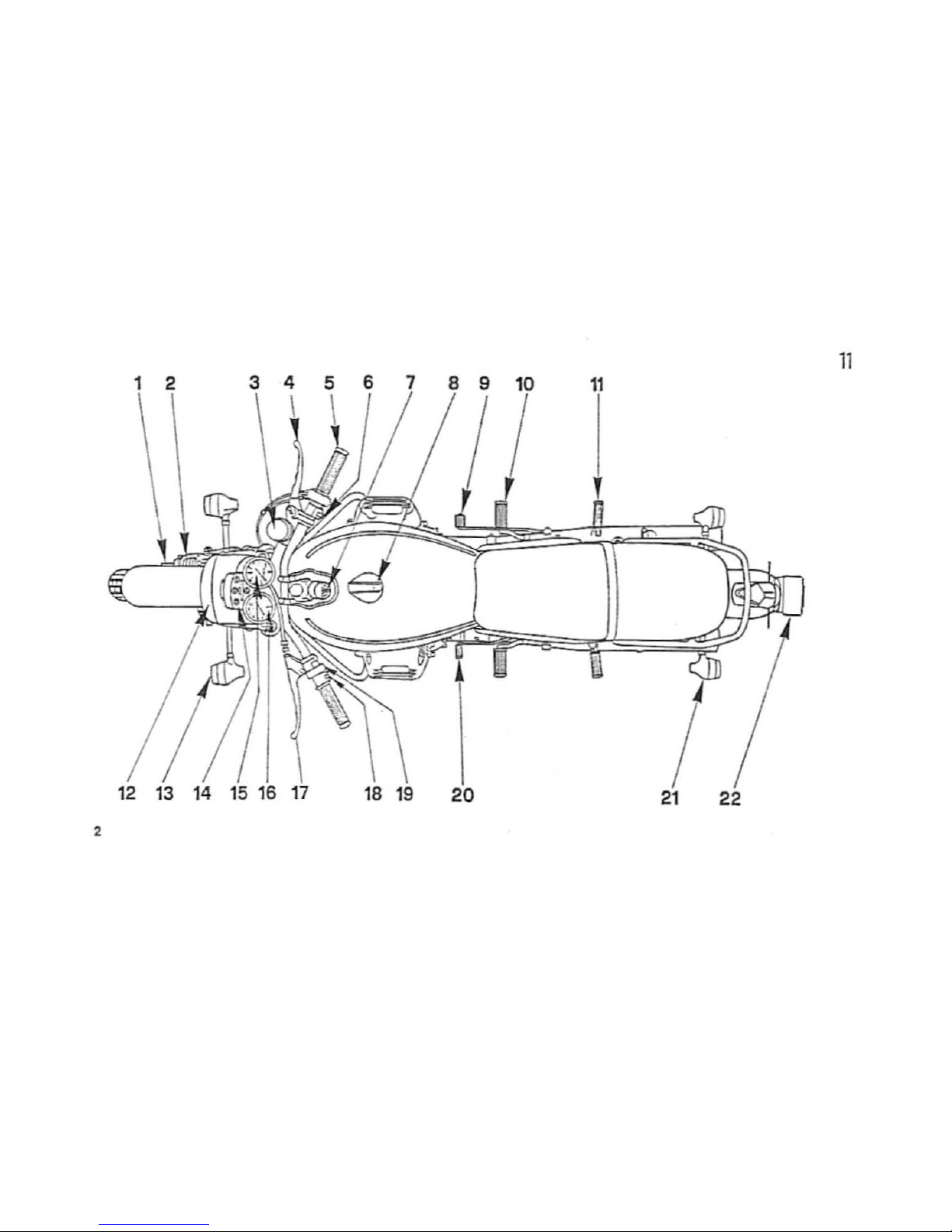
CONTROLS AND ACCESSORIES
(fig. 2)
1 Front brake disc.
2 Front brake pliers.
3
Pump and fluid reservoir,
front
bra ke.
4 Front
brake
contro
l lever.
S
Throttle
contro
l grip.
6 Starter and engine
emergency
stop.
7 Key
switch
.
8 Fuel filler cap.
9 Rear brake pedal.
10 Footrest
11
Footrest passenger.
12
Head
ligh
t.
13 Fro
nt
turn signa
ls.
14
Indicator panel.
15
Mile counter.
16 Rev·counter.
17
Clutch control lever.
18
Horn. flashi
ng
light and turn sigr.als bu eons.
19
Lighting switch.
20
Gearshift pedal.
21
Rear turn signals.
22
Rear
light.
Right and lelt ars Imsnded
as
if
se~n
in tiding
position.
11
12
13
14
15
18 19
21
22
2
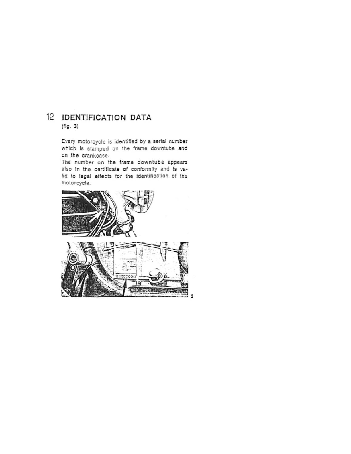
12
IDENTIFICATION DATA
(fig. 3)
E'lery
motorcyc
le is identified by a serial numoei
whic h Is stamped on the frame down tube and
on the cran kc ase.
T
he number
on
the frame
downtube
appears
also
in the certif icate
of
conformity and is
....
a
~
lid
to
leg al effec ts for the identification of the
motorcycle.
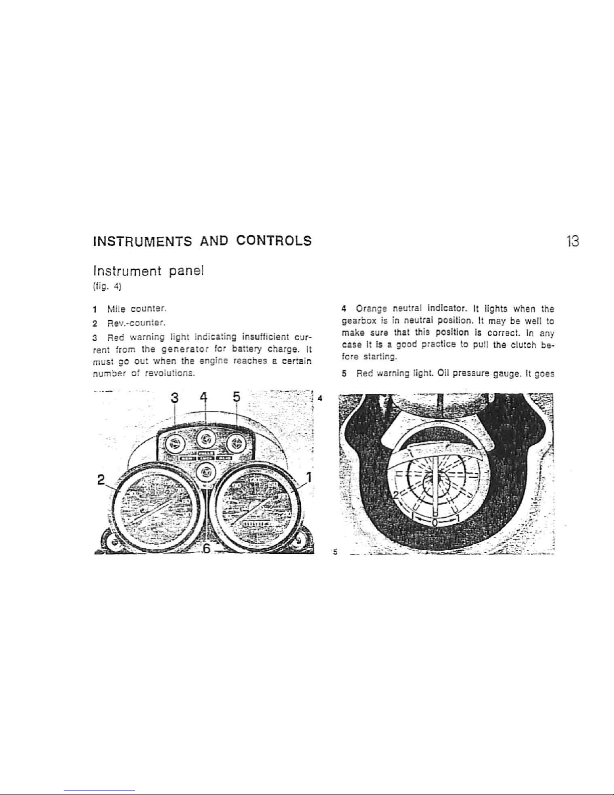
INSTRUMENTS AND CONTROLS
Instrument pan
el
(fig. 4)
M
ile
counter.
2 RS'I.
-counter.
3 Red
warning
light ind
ica
iing
insufficient cur-
fant
from
the
generator
for battery c
haige.
It
m
ust
go out when t
he
engine reach es e
cer
tain
number
of
revo
lutions.
4 Orange neutral Indicator. It lights when t
he
gearbox
is in neutral position. It may be we
ll
to
ma
ke
sure
that this positi
on
is correc!.
In any
c:~
se
It is a good pr actic e to
pu
ll the clutch be-
fore starting.
5 Red warnin
g light.
Oil
press
ure
gaug
e. It g
oes
13
14
out when the pressure is sufficient for normal
engine
lubr
ication. Should it
not
go
out, the
pre~·
sure is not
correc
t; in this case the ang ine has
to be stopped and suitable
chec
kings are to be
carried
o
ut
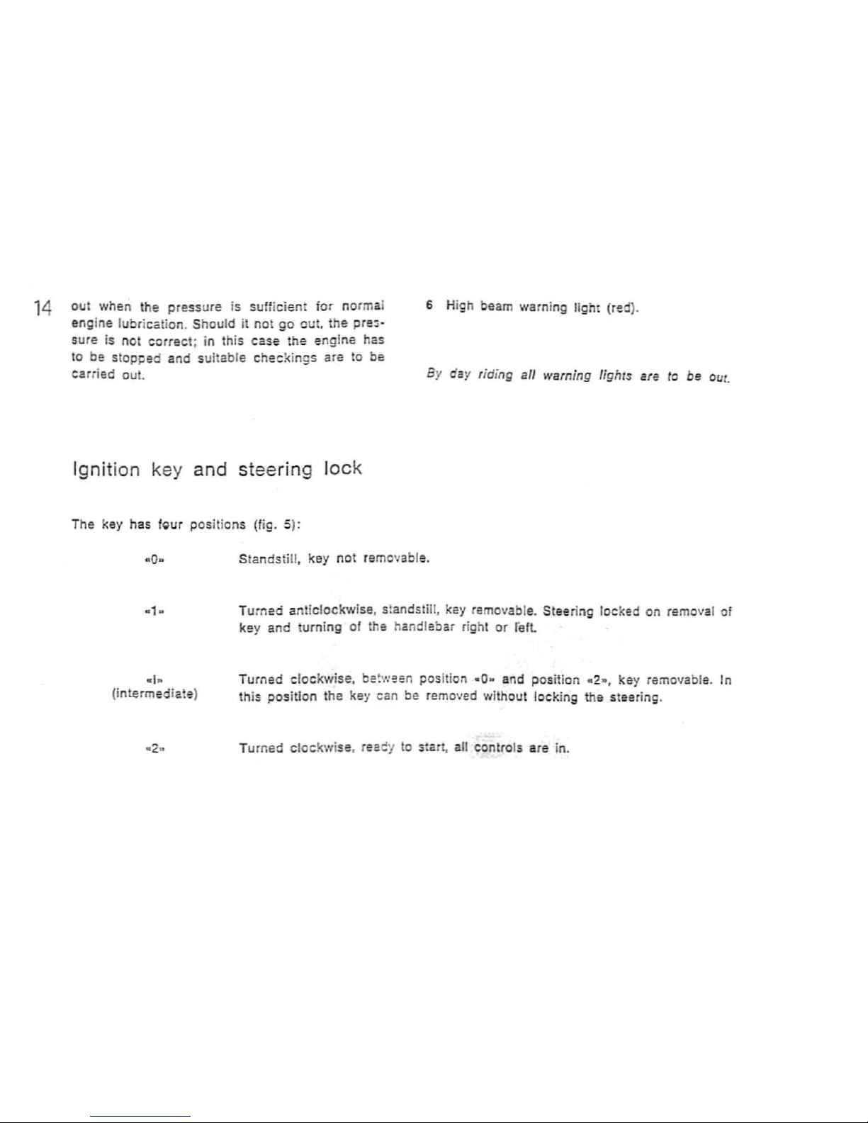
Ig
nition key and
steering
loc
k
The key has
fQur
positions (fig. 5):
6 High beam warning light (red).
By day riding
all
warning
lighls are to be out.
·0
·
Standstill . key not removable.
· 1.
(i
ntermediat e)
Turned anticlockwise, standstill, key removable. Steering
locked on removal of
key and turning of
th
e handlebar right or
refl
Turned clockwise, be!ween position
-0
..
and position -2
.,
key removable. In
this position the key can
be
remov
ed
without locki
ng
the steering.
Turned c
lockwise
. raaey
to
start, all controls are in.
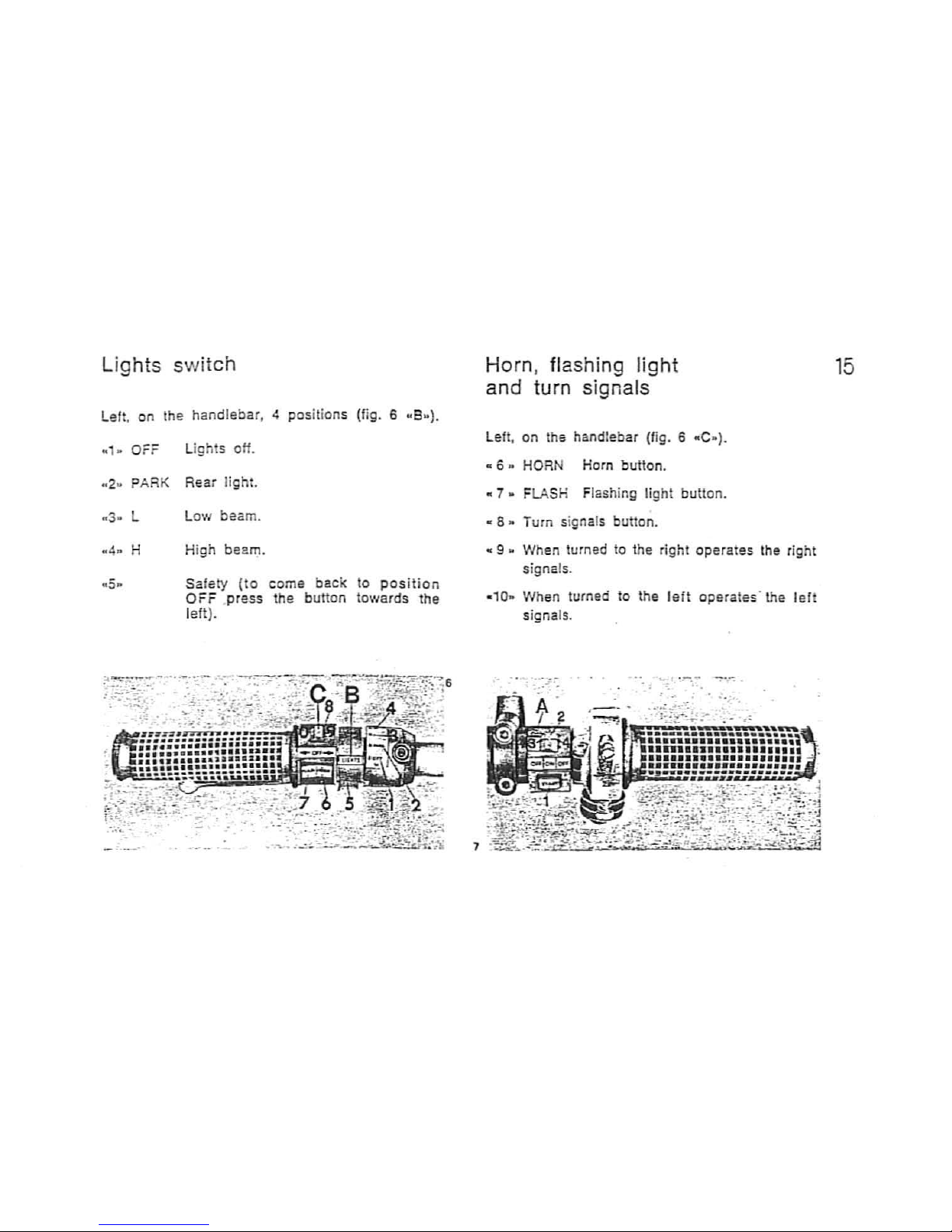
Ligh ts swi
tch
Left, on the handlebar,
-4
positions (fig. 6
..
a
..
).
.. , ..
OFF Lights oH.
.. 2 ..
PARK Rear light.
•
3.
L Low
beam.
.. 4 ..
H High
beam.
• 5. Safety
(to
come back to
posit
ion
OFF
press the button toward s
1he
lelt).
~'I.f~.::
-
....
-:
.. -.--:-:
-~.-
.
...-.
--':"
.
_l~;
Horn , flashing light
and turn signals
left,
on tho handlebar (fig. 6 - C
o)
.
• 6
.. HORN
Horn button .
.. 7 .. FLASH Flashing
light button .
.. 8 ..
Turn signals button .
.. 9 ..
When turned to the right operates t
he
right
signals .
-
10.
When turned to the l
eft
operates: the le
ft
signalS.
....
'"';.'
".
-:-
-.-
15
 Loading...