

Moto Guzzi 750 Nevada 1949-2008 Service Manual


Il contenuto del presente Manuale non è impegnativo e la Moto Guzzi S.p.A. si riserva perciò il diritto, ove
se ne presentasse la necessità, di apportare modifiche a particolari, accessori, attrezzi, ecc. che essa
ritenesse convenienti per lo scopo di miglioramento o per qualsiasi esigenza di carattere tecnico - commerciale oppure per adeguamento ai requisiti di legge dei diversi Paesi senza peraltro impegnarsi di aggiornare tempestivamente questo Manuale.
The contents of this Manual are not binding; Moto Guzzi S.p.A. therefore reserves the right to make
changes to parts, accessories, tools, etc. whenever it deems necessary in order to make improvements or
for any whatsoever technical – commercial requirements, or to comply with the provisions of the law in
individual countries, without, however, undertaking to update this Manual promptly.
MOTO GUZZI S.p.A.
Via E.V. Parodi, 57 23826 Mandello del Lario (LECCO) Italy
SERVIZIO PUBBLICAZIONE TECNICHE /
Cod. 31 92 01 83
Impianto DECA Ravenna
Stampato in Italia /
Printed in Italy
500 K - 06/02
TECHNICAL PUBBLICATIONS
da GraficheCola Lecco

PREMESSA
FOREWORD
- Questo manuale fornisce le informazioni essenziali per
le procedure di normale intervento sul veicolo.
- Le informazioni e le illustrazioni che compongono questo manuale, sono aggiornate al momento della divulgazione del manuale stesso.
- Questa pubblicazione è indirizzata ai Concessionari
Moto Guzzi S.p.A. e ai loro meccanici qualificati; molte
nozioni sono state volutamente omesse, perché giudicate superflue.
Non essendo possibile includere nozioni meccaniche
complete in questa pubblicazione, le persone che utilizzano questo manuale devono essere in possesso sia di
una preparazione meccanica di base, che di una conoscenza sulle procedure inerenti ai sistemi di riparazione
dei motoveicoli.
Senza queste conoscenze, la riparazione o il controllo
del veicolo potrebbe essere inefficiente o pericolosa.
Non essendo descritte dettagliatamente tutte le procedure per la riparazione, e il controllo del veicolo, bisogna adottare particolare attenzione al fine di evitare danni
ai componenti e alle persone. Per offrire al cliente maggiore soddisfazione dall’uso del veicolo, Moto Guzzi
S.p.A. si impegna a migliorare continuamente i propri
prodotti e la relativa documentazione. Le principali modifiche tecniche e modifiche alle procedure per le riparazioni del veicolo vengono comunicate a tutti i Punti Vendita Moto Guzzi S.p.A. e alle Filiali nel Mondo. Tali modifiche verranno apportate nelle edizioni successive di
questo manuale.
Per ulteriori informazioni vedi:
- MANUALE OFFICINA COD. 23 92 01 80
- CATALOGO RICAMBI COD. 31 92 00 83
La ditta Moto Guzzi S.p.A. si riserva il diritto di apportare modifiche in qualsiasi momento ai propri modelli, fermo restando le caratteristiche essenziali qui descritte e
illustrate.
I diritti di memorizzazione elettronica, di riproduzione e
di adattamento totale o parziale, con qualsiasi mezzo
sono riservati per tutti i Paesi.
- This manual provides the information required for normal
servicing of the motorcycle.
- The information and illustrations in this manual are up
to date at the time of going to press.
- This manual is intended for use by Moto Guzzi S.p.A.
Dealers and their qualified mechanics. Certain
information has been omitted intentionally, as this manual
does not purport to provide a comprehensive treatise on
mechanics.
The persons who use this manual must be fully
conversant with the basics of mechanics and with the
basic procedures of motorcycle repair.
Repairing or inspecting a motorcycle when one does not
possess such basic knowledge or training could result in
improper servicing and make the motorcycle unsafe to
ride.
For the same reason, certain basic precautions have
been omitted in the descriptions of repair and inspection
procedures; you are therefore invited to take special care
to avoid damage to motorcycle components or injury to
persons. Moto Guzzi S.p.A.’s mission is to enhance the
riding pleasure of end users through on-going
improvement of its products as well as of the relevant
technical literature. All Moto Guzzi S.p.A. Points of Sale
and Branches worldwide are kept updated on major
engineering changes and modifications to repair
procedures. Such changes and modifications are
reflected in successive releases of this manual.
For more details see:
- WORKSHOP MANUAL PART NUMBER 23 92 01 81
- SPARE PARTS CATALOGUE
PART NUMBER 31 92 00 83
Moto Guzzi S.p.A. reserves the right to make changes
to its products at any time, barring any such changes as
may alter the essential features of a product as specified
in this manual.
All rights of storage using electronic means, reproduction
and total or partial adaptation, whatever the means
adopted, are reserved in all countries.

NEVADA 750
NEVADA 750 CLUB

INDICE DELLE SEZIONI
INDEX FOR THE SECTIONS
I

SEZ. 1 INFORMAZIONI GENERALI PAG.
1 ABBREVIAZIONI E SIMBOLOGIA ................. 2
2 NORME GENERALI DI SICUREZZA.............. 2
SECT. 1 GENERAL INFORMATION PAG.
1 ABBREVIATIONS AND SYMBOLS ................ 2
2 GENERAL SAFETY PRESCRIPTIONS ......... 2
SEZ. 2 CARATTERISTICHE GENERALI
1 MOTORE ........................................................ 2
2 TRASMISSIONI .............................................. 3
3 TELAIO ........................................................... 3
4 DATI DI IDENTIFICAZIONE ........................... 5
SEZ. 3 LUBRIFICANTI E RIFORNIMENTI
1 OLIO MOTORE............................................... 2
2 TABELLA RIFORNIMENTI ............................. 2
SEZ. 4 PROGRAMMA DI MANUTENZIONE
1 PROGRAMMA DI MANUTENZIONE .............. 2
SEZ. 5 ATTREZZATURA SPECIFICA
COPPIE DI SERRAGGIO
E
1 ATTREZZATURA SPECIFICA ........................ 2
2 COPPIE DI SERRAGGIO ............................... 4
SEZ. 6 DATI DI CONTROLLO
1 SELEZIONATURA DEI CILINDRI E................ 2
PISTONI.......................................................... 2
2 QUOTE DI CONTROLLO PISTONE -
FASCE - SPINOTTO ....................................... 3
3 VALVOLE ........................................................ 4
4 SEDI VALVOLE .............................................. 5
5 MOLLE VALVOLE ........................................... 6
6 SISTEMA DI DISTRIBUZIONE ....................... 7
7 BIELLE ............................................................ 8
8 ALBERO MOTORE......................................... 9
9 POMPA OLIO ................................................ 10
SECT. 2 GENERAL FEATURES 1
1 ENGINE .......................................................... 2
2 TRANSMISSION............................................. 3
3 FRAME ........................................................... 3
4 IDENTIFICATION DATA.................................. 5
SECT. 3 LUBRICANTS AND SUPPLIES
1 ENGINE OIL ................................................... 2
2 LIQUID SUPPLIES CHART ............................ 2
SECT. 4 MAINTENANCE PROGRAMME
1 SERVICE SCHEDULE.................................... 3
SECT. 5 SPECIFIC TOOLS
TIGHTENING TORQUES
AND
1 SPECIFIC TOOLS .......................................... 2
2 TIGHTENING TORQUES ............................... 5
SECT. 6 CHECK DATA
1 CYLINDERS AND PISTONS SELECTION ..... 2
2 PISTON – PISTON RINGS – GUDGEON
PIN CHECKING DIMENSIONS ...................... 3
3 VALVES .......................................................... 4
4 VALVE SEATS ................................................ 5
5 VALVE SPRINGS ........................................... 6
6 TIMING SYSTEM............................................ 7
7 CONNECTING RODS .................................... 8
8 CRANKSHAFT................................................ 9
9 OIL PUMP ..................................................... 10
SEZ. 7 OPERAZIONI DI CONTROLLO
MANUTENZIONE
E
1 FRIZIONE ....................................................... 2
2 POMPA OLIO .................................................. 3
3 VALVOLA REGOLAZIONE PRESSIONE
OLIO ............................................................... 4
4 CARBURATORI .............................................. 5
5 ACCENSIONE ELETTRONICA MAGNETI
MARELLI “DIGIPLEX”................................... 11
6 CANDELE (FIG. 07-12) ................................ 13
7 ALTERNATORE - REGOLATORE
DUCATI ......................................................... 14
8 MOTORINO AVVIAMENTO (VALEO)........... 17
9 BATTERIA ..................................................... 18
10 CONTROLLO/SOSTITUZIONE PASTIGLIE
FRENI ........................................................... 21
11 REGOLAZIONE TENSIONE RAGGI
RUOTA .......................................................... 24
SECT. 7 INSPECTION AND MAINTENANCE
OPERATIONS
1 CLUTCH ......................................................... 2
2 OIL PUMP ....................................................... 3
3 OIL PRESSURE CONTROL VALVE ............... 4
4 CARBURETTORS .......................................... 5
5 MAGNETI MARELLI “DIGIPLEX”
ELECTRONIC IGNITION .............................. 11
6 SPARK PLUGS (FIG. 07-12) ........................ 13
7 DUCATI ALTERNATOR – REGULATOR ...... 14
8 STARTER MOTOR (VALEO) ........................ 17
9 BATTERY ...................................................... 18
10 BRAKE PAD CHECK/REPLACEMENT ........ 21
11 ADJUSTING WHEEL SPOKE TENSION...... 24
II
INDICE DELLE SEZIONI INDEX FOR THE SECTIONS

SEZ. 8 FORECELLA ANTERIORE
SOSTITUZIONE OLIO - REVISIONE
1 FORCELLA ANTERIORE ............................... 2
2 RIMOZIONE STELO ....................................... 4
3 INCONVENIENTI - CAUSE - RIMEDI ............ 5
4 SOSTITUZIONE OLIO FORCELLA
ANTERIORE ................................................... 6
5 SCOMPOSIZIONE / REVISIONE ................... 8
6 REVISIONE POMPANTE ............................. 11
7 RICOMPOSIZIONE ...................................... 12
SECT. 8 FRONT FORK
OIL CHANGE - OVERHAUL
1 FRONT FORK ................................................. 2
2 FORK LEG REMOVAL ................................... 4
3 PROBLEMS – CAUSES - SOLUTIONS ......... 5
4 FRONT FORK OIL CHANGE.......................... 6
5 DISASSEMBLY / OVERHAUL ........................ 8
6 PLUNGER OVERHAUL ................................ 11
7 REASSEMBLY.............................................. 12
SEZ. 9 SCHEMA IMPIANTO ELETTRICO
1 LEGENDA SCHEMA IMPIANTO
ELETTRICO “DUCATI” FINO AL TELAIO
N. LK 111944 .................................................. 3
2 LEGENDA SCHEMA IMPIANTO
ELETTRICO “SHINDENGEN” DAL TELAIO
N. LK 111945 .................................................. 5
3 MORSETTIERA PORTA FUSIBILI .................. 6
SEZ. 10 SEQUENZE DI SMONTAGGIO/
RIMONTAGGIO
1 POMPA OLIO .................................................. 2
2 VALVOLA REGOLAZIONE PRESSIONE
OLIO ............................................................... 3
3 ALTERNATORE “DUCATI” ............................. 4
4 IMPIANTO DI SCARICO................................. 5
4A SILENZIATORI ............................................... 5
4B TUBI DI SCARICO .......................................... 6
4C CAMERA DI ESPANSIONE ................................. 6
5 SERBATOIO CARBURANTE ......................... 7
6 SELLE ............................................................. 8
6A SELLA ANTERIORE (VERSIONE “BASE”) “B” ........ 8
6B SELLA POSTERIORE (VERSIONE “BASE”) “E” ...... 8
6C SELLA UNICA (VERSIONE “CLUB”) “F” ............... 8
7 PARAFANGHI ................................................. 9
7A PARAFANGO ANTERIORE ............................... 9
7B PARAFANGO POSTERIORE E PORTATARGA ...... 10
8 RUOTA ANTERIORE .................................... 11
9 RUOTA POSTERIORE ................................. 13
10 MANUBRIO................................................... 14
11 CRUSCOTTO ............................................... 15
SECT. 9 WIRING DIAGRAM
1 KEY TO WIRING DIAGRAM “DUCATI” UP TO
FRAME NO. LK 111944 .................................. 3
2 KEY TO WIRING DIAGRAM “SHINDENGEN”
FROM FRAME NO. LK 111945 ...................... 5
3 FUSE TERMINAL BLOCK .............................. 6
SECT. 10 DISASSEMBLY/
REASSEMBLY SEQUENCES
1 OIL PUMP ....................................................... 2
2 OIL PRESSURE CONTROL VALVE ............... 3
3 “DUCATI” ALTERNATOR ................................ 4
4 EXHAUST SYSTEM ....................................... 5
4A SILENCERS .................................................. 5
4B EXHAUST PIPES ............................................ 6
4C EXPANSION CHAMBER .................................... 6
5 FUEL TANK..................................................... 7
6 SEATS ............................................................ 8
6A FRONT SEAT (“STANDARD” VERSION) “B” .......... 8
6B REAR SEAT (“STANDARD” VERSION) “E” ........... 8
6C ONE-PIECE SEAT (“CLUB” VERSION) “F” ........... 8
7 MUDGUARDS ................................................ 9
7A FRONT MUDGUARDS ..................................... 9
7B REAR MUDGUARD AND REGISTRATION PLATE
HOLDER
8 FRONT WHEEL ............................................ 11
9 REAR WHEEL .............................................. 13
10 HANDLEBARS.............................................. 14
11 DASHBOARD ............................................... 15
.................................................... 10
INDICE DELLE SEZIONI INDEX FOR THE SECTIONS
III

IV

INFORMAZIONI GENERALI
GENERAL INFORMATION
1
2
3
4
5
6
7
8
9
10
1

1 ABBREVIAZIONI E SIMBOLOGIA
1 ABBREVIATIONS AND SYMBOLS
Allo scopo di rendere la lettura di immediata comprensione i paragrafi sono stati contraddistinti da illustrazioni
1
schematiche che evidenziano l’argomento trattato.
In questo manuale sono state riportate note informative
con significati particolari:
Norme antinfortunistiche per l’operatore e per
2
chi opera nelle vicinanze.
Esiste la possibilità di arrecare danno al veicolo e/o ai suoi componenti.
Ulteriori notizie inerenti l’operazione in corso
3
N.B. La “destra” o la “sinistra” é riferita ai comandi visti dalla posizione di guida.
N.B. Tutti i disegni tecnici del manuale utilizzano misure espresse in mm. e coppie di serraggio
4
espresse in Nm.
In order to optimise the clarity of this manual, the headings are marked by schematic illustrations summarising
the relative subject matter.
This manual contains informative notes with specific
meanings:
Safety prescriptions for the operator and persons working in the area.
Risk of damaging the motorcycle and/or its
parts.
Further information concerning the current task
N.B. The indications “right” or “left” refer to the
controls viewed from the riding position.
N.B. All technical drawings in the manual use
measurements in mm and tightening torques
in Nm.
5
2 NORME GENERALI DI SICUREZZA
OSSIDO DI CARBONIO
Se è necessario far funzionare il motore per poter effet-
6
tuare qualche operazione, assicurarsi che questo avvenga in uno spazio aperto o in un locale ben ventilato.
Non fare mai funzionare il motore in spazi chiusi.
Se si opera in uno spazio chiuso. Utilizzare un sistema
di evacuazione dei fumi di scarico.
7
8
9
PERICOLO
I fumi di scarico contengono ossido di carbonio,
un gas velenoso che può provocare la perdita
di conoscenza e anche la morte.
Far funzionare il motore in uno spazio aperto o, se si
opera in uno spazio chiuso, utilizzare un sistema di evacuazione dei fumi di scarico.
CARBURANTE
Operare in uno spazio ben ventilato. Tenere sigarette,
fiamme o fonti di scintille lontano dalla zona di lavoro e
dalla zona in cui il carburante viene conservato.
2 GENERAL SAFETY PRESCRIPTIONS
CARBON MONOXIDE
When an operation must be performed with the engine
running, position the motorcycle outdoors or in a wellventilated area.
Never run the engine in an enclosed place.
If running the engine indoors use an extraction system
for the exhaust gas.
DANGER
Exhaust emissions contain carbon monoxide,
a poisonous gas that may cause loss of consciousness or even death.
Run the engine outdoors or, if working indoors, use an
exhaust emission extraction system.
FUEL
Work in a well-ventilated area. Keep cigarettes, flames,
and sources of sparks well clear of the work area and
the area in which fuel is stored.
10
PERICOLO
Il carburante è altamente infiammabile e in al-
cune condizioni diventa esplosivo.
TENERE LONTANO DALLA PORTATA DEI BAM-
BINI.
2
INFORMAZIONI GENERALI
DANGER
Fuel is highly flammable and may assume ex-
plosive properties in certain circumstances.
KEEP AWAY FROM CHILDREN.
GENERAL INFORMATION

COMPONENTI AD ALTE TEMPERATURE
PERICOLO
Il motore e i componenti dell’impianto di scari-
co diventano molto caldi e rimangono caldi per
un certo periodo anche dopo che il motore è
stato spento. Prima di maneggiare questi componenti, indossare guanti isolanti o attendere
fino a che il motore e l’impianto di scarico si
sono raffreddati.
COMPONENTS AT HIGH TEMPERATURES
DANGER
The engine and exhaust component parts be-
come hot when the engine is running and will
stay hot for some time after the engine has been
stopped. Wear heat insulated gloves before handling these components or allow time for the
engine and exhaust system to cool down before proceeding.
1
2
OLIO MOTORE ESAUSTO
PERICOLO
Utilizzare guanti in lattice per le operazioni di
manutenzione che prevedono il contatto con
l’olio. L’olio esausto del motore, se viene
ripetutamente lasciato a contatto con la pelle
per periodi prolungati, può causare il cancro
della pelle. Sebbene questo sia improbabile, a
meno che non si maneggi olio esausto quotidianamente, si consiglia di lavare le mani accuratamente con acqua e sapone nel caso venga
maneggiato.
TENERE LONTANO DALLA PORTATA DEI BAMBINI.
PRECAUZIONI E INFORMAZIONI GENERALI
Per garantire che il veicolo sia sempre in perfette
condizioni di funzionamento è necessario attenersi
alle istruzioni fornite nel programma di manutenzione periodica descritto nella sezione 4.
La prima serie di operazioni di manutenzione è da
eseguire dopo 1500 Km come riportato nella tabella del cap. 1 della sez. 4; l’esecuzione di tali operazioni è importantissima in quanto consentono di
controllare l’usura iniziale che avviene in corrispondenza del rodaggio.
E’ inoltre importante quando si esegue la riparazione, lo smontaggio e il rimontaggio del veicolo attenersi scrupolosamente alle seguenti raccomandazioni.
SPENT ENGINE OIL
DANGER
Wear rubber gloves for maintenance work that
involves contact with oil. If left repeatedly in
contact with the skin for prolonged periods,
spent engine oil may cause skin cancer. Even
though this eventuality is remote unless spent
oil is handled daily, it is advisable to wash the
hands thoroughly with soap and water after
handling spent oil.
KEEP AWAY FROM CHILDREN.
GENERAL PRECAUTIONS AND INFORMATION
To ensure that the motorcycle is in perfect running
order adhere strictly to the instructions provided in
the periodic maintenance programme described in
section 4.
The first series of maintenance operations must be
performed after 1500 km (1000 miles) as indicated
in chap. 1 of section 4; execution of these operations is of the maximum importance because they
make it possible to check initial wear sustained
during running in.
It is also important to adhere strictly to the following
instructions when repairing, disassembling or reassembling the motorcycle or its components.
3
4
5
6
7
PERICOLO
Per qualsiasi tipo di operazione è vietato l’uso
di viva fiamma.
Prima di iniziare qualsiasi intervento di manutenzione o ispezione al veicolo, arrestare il motore e togliere la chiave, attendere che motore
e impianto di scarico si siano raffreddati, sollevare possibilmente il veicolo, con apposita attrezzatura, su pavimento solido e in piano.
Porre particolare attenzione alle parti ancora
calde del motore e dell’impianto di scarico, in
modo tale da evitare ustioni.
Il veicolo è costruito con parti non commestibili; non mordere, succhiare, masticare o ingerire nessuna parte dello stesso per nessun motivo.
Se non espressamente descritto, il rimontaggio
dei gruppi segue in senso inverso le operazioni
di smontaggio.
INFORMAZIONI GENERALI GENERAL INFORMATION
DANGER
Using bare flames is strictly forbidden when
working on the motorcycle.
Before servicing or inspecting the motorcycle:
stop the engine and remove the key from the
ignition switch; allow the engine and exhaust
system to cool down; where possible, lift the
motorcycle using adequate equipment placed
on firm and level ground.
Pay particular attention to any parts of the engine or exhaust system that may still be hot to
the touch to avoid burns.
No parts of the motorcycle are edible; do not
bite, suck, chew, or swallow any of the parts for
any whatsoever reason.
If not expressly indicated otherwise, for the
reassembly of the units repeat the disassembly
operations in reverse order.
8
9
10
3

1
2
L’eventuale sovrapposizione di operazioni nei
vari rimandi ad altri capitoli deve essere interpretata con logica, evitando così rimozioni non
necessarie di componenti.
Non utilizzare mai il carburante come solvente
per la pulizia del veicolo.
Scollegare il cavo negativo () della batteria, in
caso si debbano eseguire saldature elettriche.
Quando due o più persone lavorano contemporaneamente, prestare attenzione alla sicurezza di ciascuno.
Where a procedure is cross-referred to relevant
sections in the manual, proceed sensibly to
avoid disturbing any parts unless strictly necessary.
Never use fuel instead of solvent to clean the
motorcycle.
Always disconnect the battery negative (–) lead
before soldering any electrical components.
When two or more persons service the same
motorcycle together, special care must be taken
to avoid personal injury.
PRIMA DELLO SMONTAGGIO
- Rimuovere lo sporco, il fango, la polvere e i corpi estra-
3
nei dal veicolo prima dello smontaggio dei componenti.
- Impiegare, dove previsto, gli attrezzi speciali progettati
per questo veicolo.
SMONTAGGIO DEI COMPONENTI
- Contrassegnare le posizioni su tutti i giunti di connes-
4
5
sioni (tubi, cavi, ecc.) prima di dividerli e identificarli
con segni distintivi differenti.
Ogni pezzo va segnato chiaramente per poter essere
identificato in fase di installazione.
- Pulire e lavare accuratamente i componenti smontati,
con detergente a basso grado di infiammabilità.
- Tenere insieme le parti accoppiate tra di loro, perché si
sono “adattate” l’una all’altra in seguito alla normale
usura.
Alcuni componenti devono essere utilizzati assieme oppure sostituiti completamente.
- Tenersi lontani da fonti di calore.
6
RIMONTAGGIO DEI COMPONENTI
ATTENZIONE
Non riutilizzare mai un anello elastico, quando
viene smontato deve essere sostituito con uno
7
8
nuovo.
Quando si monta un anello elastico nuovo, fare
attenzione a non allontanare le sue estremità
più dello stretto necessario per infilarlo sull’albero.
Dopo il montaggio di un anello elastico, verificare che sia completamente e saldamente inserito nella sua sede.
PRIOR TO DISASSEMBLY
- Clean off all dirt, mud, and dust and remove any foreign objects from the motorcycle before disassembling
any components.
- Use model-specific special tools where specified.
DISASSEMBLING THE COMPONENTS
- Mark all connections (hoses, wiring, etc.) with their positions before disconnecting them. Identify each connection using a different symbol.
Mark each part clearly to avoid confusion when refitting.
Thoroughly clean and wash any components you have
removed using a detergent with low flash point.
- Keep connected parts together since they will have
seated themselves against one another as a result of
normal wear.
Certain components are matched-pair parts and should
always be used together or replaced as a set.
- Keep the motorcycle and its parts well away from heat
sources.
REASSEMBLING THE COMPONENTS
WARNING
Never reuse circlips or snap rings. These parts
must always be renewed once they have been
disassembled.
When fitting a new circlip or snap ring, open
the ends just sufficiently to allow fitment to the
shaft.
Make a rule to check that a newly–fitted circlip
or snap ring has located fully into its groove.
9
10
Non utilizzare aria compressa per la pulizia dei
cuscinetti.
IMPORTANTE:
I cuscinetti devono ruotare liberamente, senza
impuntamenti e/o rumorosità, altrimenti devono essere sostituiti.
4
INFORMAZIONI GENERALI
Never use compressed air to clean bearings.
IMPORTANT:
All bearings must rotate freely with no stiffness
or noise. Renew any bearings that do not meet
these requirements.
GENERAL INFORMATION

- Utilizzare esclusivamente RICAMBI ORIGINALI Moto
Guzzi.
- Attenersi all’impiego dei lubrificanti e del materiale di
consumo consigliato.
- Lubrificare le parti (quando è possibile) prima di rimontarle.
- Nel serraggio di viti e dadi, iniziare con quelli di diametro maggiore oppure quelli interni, procedendo in diagonale. Eseguire il serraggio con passaggi successivi,
prima di applicare la coppia di serraggio.
- Sostituire sempre le guarnizioni, gli anelli di tenuta, gli
anelli elastici, gli anelli O-Ring (OR) e le copiglie con
altri nuovi.
Pulire tutti i piani di giunzione, i bordi dei paraolio e le
guarnizioni prima del rimontaggio.
Applicare un leggero velo di grasso a base di litio sui
bordi dei paraolio.
Rimontare i paraolio e i cuscinetti con il marchio o numero di fabbricazione rivolti verso l’esterno (lato visibile).
Quando si montano i cuscinetti, lubrificarli abbondantemente.
- Controllare che ogni componente sia stato montato in
modo corretto.
- Dopo un intervento di riparazione o di manutenzione
periodica, effettuare i controlli preliminari e collaudare
il veicolo in una proprietà privata o in una zona a bassa
intensità di circolazione.
- Use genuine ORIGINAL Moto Guzzi SPARE PARTS
only.
- Use exclusively the recommended lubricants and
consumables.
- Wherever possible, lubricate parts before assembly.
- When tightening nuts and bolts, start with the largest or
innermost nut/bolt and proceed in a crosswise pattern.
Tighten evenly in subsequent steps until achieving the
specified torque.
- Always renew all gaskets, seals, circlips or snap rings,
O-rings and split pins.
Clean all mating surfaces, oil seal edges and gaskets
before assembly.
Apply a light coat of lithium grease along the edges of
oil seals.
Fit oil seals and bearings with the brand or serial number
facing outwards (in view).
Lubricate bearings abundantly before assembly.
- Make a rule to check that all components you have
fitted are correctly in place.
- After repairing the motorcycle and after each service
inspection, perform the preliminary checks, and then
road test the motorcycle in a private estate area or in a
safe area away from traffic.
1
2
3
4
5
6
7
8
9
INFORMAZIONI GENERALI GENERAL INFORMATION
10
5

1
2
3
4
5
6
7
8
9
10
6

CARATTERISTICHE GENERALI
GENERAL FEATURES
1
2
3
4
5
6
7
8
9
10
1
1 MOTORE
1 ENGINE
Ciclo ..................................................... a quattro tempi
N. cilindri .................................................................... 2
1
Disposizione cilindri.................................... a "V" di 90°
Alesaggio ......................................................... 80 mm
Corsa................................................................ 74 mm
Cilindrata totale ............................................. 743,9 cc
Rapporto di compressione ................................... 9,6:1
2
DISTRIBUZIONE
A valvole in testa con aste e bilancieri.
DATI DELLA DISTRIBUZIONE
ASPIRAZIONE:
■ apre 18° prima del P.M.S.
3
■ chiude 50° dopo il P.M.I.
SCARICO:
■ apre 53° prima del P.M.I.
■ chiude 15° dopo il P.M.S.
Gioco alle valvole per controllo messa in fase distribu-
4
zione: 1mm
Gioco di funzionamento tra bilancieri e valvole:
■ aspirazione: ................................................ 0,15 mm
■ scarico: ...................................................... 0,20 mm
Cycle ............................................................... 4-stroke
N. cylinders ................................................................ 2
Cylinder configuration .................................. 90° V-twin
Bore.................................................................. 80 mm
Stroke ................................................................ 74 mm
Capacity ......................................................... 743.9 cc
Compression ratio ................................................ 9.6:1
TIMING SYSTEM
Valve gear data
TIMING SYSTEM DATA
INTAKE:
■ Opens 18° before TDC
■ Closes 50° after BDC
EXHAUST:
■ Opens 53° before BDC
■ Closes 15° after TDC
Valve timing clearance check: 1 mm
Rocker arm/valve working clearance:
■ intake: ......................................................... 0.15 mm
■ exhaust: ...................................................... 0.20 mm
5
LUBRIFICAZIONE
Forzata con pompa a lobi e spia insufficiente pressione
situata sul cruscotto.
Filtri olio: a rete all'interno della coppa ed a cartuccia
sostituibile dall'esterno.
6
ACCENSIONE
Elettronica digitale a scarica induttiva “MAGNETI
MARELLI - DIGIPLEX”.
I tipi di candela da impiegare sono:
■ NGK-BRE8ES, CHAMPION-RN3C, BOSCH-WR4CC.
Distanza fra gli elettrodi: 0,7 mm
7
ALIMENTAZIONE
N. 2 carburatori Dell'Orto tipo "PHBH 30 BD/BS"
SCARICO
N. 2 tubi e N. 2 silenziatori collegati.
8
GENERATORE ALTERNATORE
Montato sulla parte anteriore dell'albero motore.
Potenza di uscita: 350W a 5000 giri (14V - 25A).
LUBRICATION
Pressure fed by gear pump with low oil warning lamp on
instrument panel.
Oil filters: wire mesh inside sump and replaceable
cartridge filter outside sump.
IGNITION
“MAGNETI MARELLI - DIGIPLEX” Inductive discharge
digital electronics.
We recommend the following types of spark plugs:
■ NGK-BRE8ES, CHAMPION-RN3C, BOSCH-WR4CC.
Spark plug gap: 0.7 mm
CARBURETORS
2 Dell’Orto carburetors “PHBH 30 BD/BS”
EXHAUST
2 pipes and 2 connected silencers.
GENERATOR/ALTERNATOR
On front of crankshaft.
Output power: 350W at 5000 rev/min (14V - 25A).
9
10
AVVIAMENTO
Elettrico mediante apposito motorino (12 V - 1,2 KW)
munito di innesto a comando elettromagnetico.
Comando a pulsante (START) " " posto sul lato destro
del manubrio.
2
CARATTERISTICHE GENERALI GENERAL FEATURES
STARTING
Electric starter motor (12 V - 1.2 kw) with electromagnetic
ratchet control.
(START) " " push-button on right handlebar.

2 TRASMISSIONI
2 TRANSMISSION
FRIZIONE
Tipo monodisco a secco con molla a diaframma; comando a mano con leva posta sul lato sinistro del manubrio.
TRASMISSIONE PRIMARIA
Ad ingranaggi, rapporto 1:3125 (Z=16/21).
CAMBIO
A 5 marce con ingranaggi sempre in presa ad innesto
frontale. Comando con leva posta al centro del motociclo
sul lato sinistro.
Rapporti cambio:
1a marcia = 1:2,3636 (Z=11/26)
2a marcia = 1:1,6428 (Z=14/23)
3a marcia = 1:1,2777 (Z=18/23)
4a marcia = 1:1,0555 (Z=18/19)
5a marcia = 1:0,9000 (Z=20/18)
TRASMISSIONE SECONDARIA
Ad albero con giunto cardanico e coppia conica.
Rapporto: 1:3,875 (Z=8/31).
Rapporti totali (motore-ruota):
1a marcia = 1:12,0213
2a marcia = 1: 8,3555
3a marcia = 1: 6,4987
4a marcia = 1: 5,3685
5a marcia = 1: 4,5773
CLUTCH
Single driven disk, dry type with spring; hand controlled
by lever on left-hand side of handlebars.
PRIMARY DRIVE
By gears, ratio 1:3125 (tooth ratio = 16/21).
TRANSMISSION
5 speeds, frontal engagement, constant mesh gears.
Pedal operated on central left-hand side of the
motorcycle.
Gear ratios:
1st gear = 1:2.3636 (Z = 11/26)
2ndgear = 1:1.6428 (Z = 14/23)
3rd gear = 1:1.2777 (Z = 18/23)
4th gear = 1:1.0555 (Z = 18/19)
5st gear = 1:0.9000 (Z = 20/18)
SECONDARY TRANSMISSION
By shaft, with universal joint and bevel gear.
Ratio: 1:3.875 (Z = 8/31).
Overall gear ratios (engine-wheel):
1st gear = 1:12.0213
2nd gear = 1: 8.3555
3rd gear = 1: 6.4987
4th gear = 1: 5.3685
5st gear = 1: 4.5773
1
2
3
4
5
3 TELAIO
Tubolare a doppia culla scomponibile in acciaio ad alto
limite di snervamento
SOSPENSIONI
Anteriore: forcella telescopica idraulica "MARZOCCHI",
Ø 40 mm.
Posteriore: forcellone oscillante presso fuso in lega leggera con due ammortizzatori regolabili nel precarico molle
e nella frenatura idraulica.
RUOTE
A raggi con cerchi in acciaio nelle misure:
■ anteriore: 2,15 x 18"
■ posteriore: 2,50 x 16"
PNEUMATICI
MICHELIN
Anteriore: 100/90 18-56V Macadam 50E
Posteriore: 130/90 16-65V Macadam
PIRELLI
Anteriore: 100/90 H18 MT69 E
Posteriore: 130/90 H16 MT68 E
METZELER
Anteriore: 100/90 V18 TL 56 V
Posteriore: 130/90 16 TL 67 V
3 FRAME
Tubular structure with dismountable double-cradle frame made of high yield stress steel
SUSPENSIONS
Front: “MARZOCCHI” hydraulic telescopic fork, Ø 40 mm.
Rear: die-cast swinging arm in light metal with two shock
absorbers with adjustable preloaded springs and
adjustable hydraulic braking.
WHEELS
Spoked, with steel rims.Rim sizes:
■ front: 2.15 x 18"
■ rear: 2.50 x 16"
TYRES
MICHELIN
Front: 100/90 18-56V Macadam 50E
Rear: 130/90 16-65V Macadam
PIRELLI
Front: 100/90 H18 MT69 E
Rear: 130/90 H16 MT68 E
METZELER
Front: 100/90 V18 TL 56 V
Rear: 130/90 16 TL 67 V
6
7
8
9
10
CARATTERISTICHE GENERALI GENERAL FEATURES
3
FRENI
Anteriore: disco flottante in acciaio inox brembo "serie
oro" con pinza fissa a 4 pistoncini differenziati.
1
Comando con leva a mano posta sul lato destro del
manubrio.
– Ø disco 320 mm
– Ø cilindro frenante 34/30 mm
– Ø pompa 13 mm
Posteriore: a disco fisso in acciaio inox con pinza a dop-
2
pio cilindro frenante. Comando con leva a pedale posta
al centro sul lato destro del motociclo.
– Ø disco 260 mm
– Ø cilindro frenante 32 mm
– Ø pompa 16 mm
3
INGOMBRI E PESO
Passo (a carico) ............................................ 1,482 m
Lunghezza massima ..................................... 2,205 m
Larghezza massima ........................................ 0,875 m
Altezza massima ............................................. 1,180 m
Altezza sella .................................................. 0,770 m
4
Peso a secco (versione Club) .......................... 182 kg
Peso a secco (versione base) .......................... 176 kg
BRAKES
Front: Brembo “Gold Series” floating disk in stainless steel
with fixed caliper and 4 separated pistons.
Brake hand lever on the right-hand side of the handlebar.
– Ø disk 320 mm
– Ø brake cylinder 34/30 mm
– Ø master cylinder 13 mm
Rear: stainless steel fixed disk with twin-piston brake
caliper. Brake pedal in the center on the right-hand side
of the motorbike.
– Ø disk 260 mm
– Ø brake cylinder 32 mm
– Ø master cylinder 16 mm
DIMENSIONS AND WEIGHT
Wheelbase (loaded) ........................................ 1.482 m
Overall length .................................................. 2.205 m
Overall width ................................................... 0.875 m
Height .............................................................. 1.180 m
Saddle height .................................................. 0.770 m
Dry weight (Club version) .................................. 182 kg
Dry weight (standard version) ........................... 176 kg
5
6
7
8
N.B. Il motoveicolo può essere equipaggiato a
richiesta con parabrezza che consente una guida confortevole, e borse asportabili.
Tutti questi volumi comportano però una limitazione all’aerodinamica del veicolo. E’
consigliabile pertanto, specie in condizioni di
carico massimo, non superare la velocità di 130
Km/h circa.
On request the motor vehicle can be equipped
with a windshield which allows comfortable
driving, and removable sidebags.
These items do however after the aerodynamic
features of the bike; it is advisable therefore not
to exceed 130 kph especially when the bike is
fully loaded.
9
10
4
CARATTERISTICHE GENERALI GENERAL FEATURES
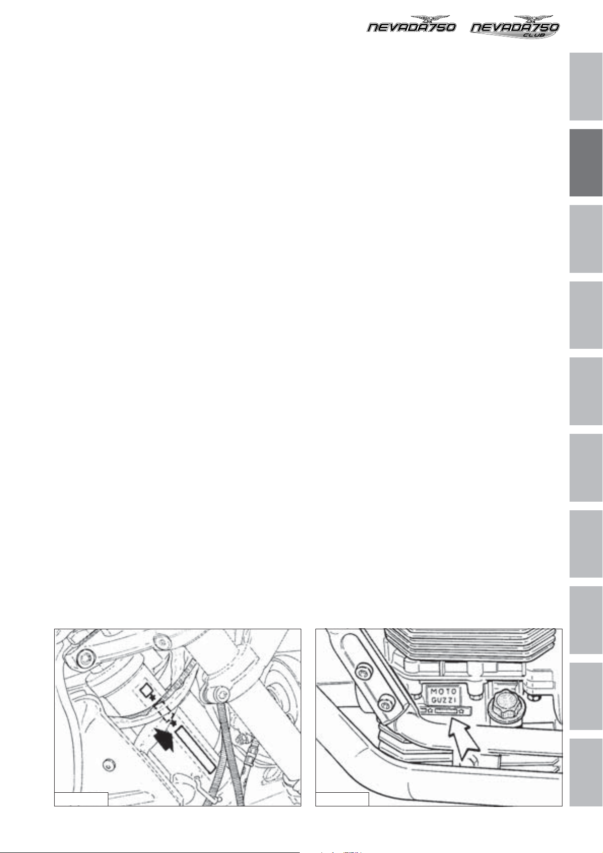
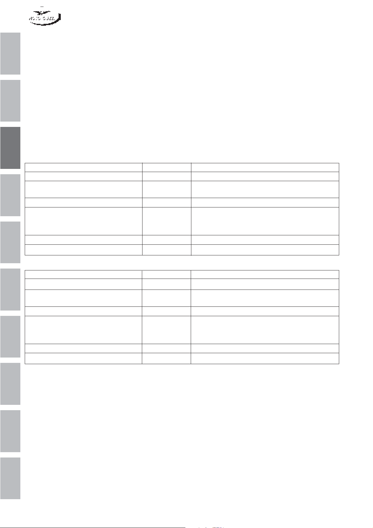
4 DATI DI IDENTIFICAZIONE
4 IDENTIFICATION DATA
Ogni veicolo è contraddistinto da un numero di identificazione impresso sulla pipa del telaio e sul basamento
motore.
Il numero impresso sulla pipa del telaio è riportato sul
libretto di circolazione e serve agli effetti di legge per
l'identificazione del motociclo stesso; questo numero è
composto da cifre e lettere come nell’esempio sotto riportato.
MARCATURA DEL TELAIO
✩ZGULK01001M111111✩
Legenda:
ZGU: codice WMI (World manufacture identifier);
LK: tipo di veicolo;
0100: variante versione normale (0101 CATALIZZA-
TA);
1: anno di fabbricazione variabile (1 per 2001 - 2
per 2002);
M: stabilimento di produzione;
111111: numero progressivo.
Each vehicle is marked by an identification number
stamped on the chassis lug and on the engine crankcase.
The number marked on the chassis lug and reported in
the registration document is the legal identification of the
motorbike; this number is composed of digits and letters,
as in the example illustrated below.
FRAME MARKING
✩ZGULK01001M111111✩
Key:
ZGU: WMI (World manufacture identifier) code;
LK: motorcycle type;
0100: variant of normal version (0101 CATALYTIC
CONVERTER);
1: Year of production (1 for 2001 - 2 for 2002);
M: production plant;
111111: sequential number
1
2
3
4
5
6
7
8
Fig. 02-01 Fig. 02-02
CARATTERISTICHE GENERALI GENERAL FEATURES
9
10
5

1
2
3
4
5
6
7
8
9
10
6

LUBRIFICANTI E RIFORNIMENTI
LUBRICANTS AND SUPPLIES
1
2
3
4
5
6
7
8
9
10
1
1 OLIO MOTORE
1 ENGINE OIL
Un buon olio motore ha delle particolari qualità.
Fate uso solamente di olio motore altamente detergen-
1
te, certificato sul contenitore come corrispondente, o superiore, alle necessità di servizio SE, SF o SG.
2
2 TABELLA RIFORNIMENTI
3
Parti da rifornire Litri Prodotti da impiegare
Serbatoio carburante (riserva 4 lt circa) 14 Benzina senza piombo (95 NO-RM/min.)
Coppa motore 2 Olio "Agip SUPER 4T SAE 15W/50"
4
Scatola cambio 1,000 Olio "Agip Rotra MP SAE 80 W/90"
Scatola trasmissione posteriore 0,170 di cui:
5
Forcella telescopica (per gamba) 0,400 Olio per ammortizzatori "SAE 10"
Impianto frenante anteriore e posteriore — Fluido "Agip Brake Fluid - DOT4"
Good engine oils offer special features. Only use oils
with high detergent power, certified as equivalent or
superior to SE, SF or SG duty (this is marked on the
container).
2 LIQUID SUPPLIES CHART
Olio "Agip RACING 4T SAE 5W/40"
0,160 Olio "Agip Rotra MP SAE 85 W/140"
0,010 Olio "Agip Rocol ASO/R" oppure "Molykote tipo A"
6
7
8
9
Description Quantity Recommended products
Fuel tank (reserve approx 4 lt) 14 Unleaded petrol (95 NO-RM/min.)
Oil sump 2 "Agip SUPER 4T SAE 15W/50" oil
"Agip RACING 4T SAE 5W/40 oil
Gear box 1.000 “Agip Rotra MP SAE 80 W/90” oil
Rear drive box (bevel set lub) 0.170 of which:
0.160 “Agip Rotra MP SAE 85 W/140” oil
0.010 “Agip Rocol ASO/R” oil or “Molykote type A” oil
Front fork (each leg) 0.400 Shock-Absorber oil "SAE 10"
Braking circuits (front and rear) — "Agip Brake Fluid - DOT4" fluid
10
2
LUBRIFICANTI E RIFORNIMENTI
LUBRICANTS AND SUPPLIES

PROGRAMMA DI MANUTENZIONE
MAINTENANCE PROGRAMME
1
2
3
4
5
6
7
8
9
10
1
1
2
3
4
sibili; ai 500 km controllare il livello
5
6
7
8
1500 Km 5000 Km 10000 Km 15000 Km 20000 Km 25000 Km 30000 Km 35000 Km 40000 Km 45000 Km 50000 Km
9
10
PERCORRENZE
OPERAZIONI
Olio motore RRR RR R R RRRR
Filtro olio a cartuccia RRR RR R R RRRR
Filtro olio a rete CC C
Filtro aria RR RR R R RRRR
Candele RR RR R R RRRR
Giuoco valvole AAA AA A A AAAA
Carburazione AAA AA A A AAAA
Serraggio bulloneria AAA AA A A AAAA
Tubazioni CC C C C C
1 PROGRAMMA DI MANUTENZIONE
2
PROGRAMMA DI MANUTENZIONE
Olio cambio RAR AR A R ARAR
Olio trasmissione posteriore RAR AR A R ARAR
Cuscinetti ruote e sterzo AA
Olio forcella anteriore RR R
Motorino avviamento e generatore AA
Fluido impianto frenante AAA AR A A ARAA
Pastiglie freni AAA AA A A AAAA
Serraggio dadi teste cilindro A
dell'olio motore.
A = Manutenzione - Controllo - Regolazione - Eventuale sostituzione. / C = Pulizia. / R = Sostituzione.
Saltuariamente controllare il livello dell'elettrolito nella batteria e lubrificare le articolazioni dei comandi ed i cavi fles
In ogni caso sostituire l'olio motore, il filtro olio ed il fluido frenante almeno una volta all'anno.
Controllare periodicamente la tensione dei raggi.
MAINTENANCE PROGRAMME
(300 miles) check the engine oil
1
2
3
4
(1500 Km) (5000 Km) (10000 Km) (15000 Km) (20000 Km) (25000 Km) (30000 Km) (35000 Km) (40000 Km) (45000 Km) (50000 Km)
5
6
7
8
MILEAGE COVERED 1000 mi. 3000 mi. 6000 mi. 9000 mi. 12000 mi. 15000 mi. 18000 mi. 21000 mi. 24000 mi. 27000 mi. 30000 mi.
ITEMS
Engine oil RRRRRRRRRRR
Oil filter cartridge RRRRRRRRRRR
1 SERVICE SCHEDULE
Wire gauze oil filter CC C
PROGRAMMA DI MANUTENZIONE
Air filter RRRRRRRRRR
Spark plugs RRRRRRRRRR
Rocker clearance AAAAAAAAAAA
Carburation AAAAAAAAAAA
Nuts and bolts AAAAAAAAAAA
Pipes CC C C C C
Gearbox oil RARARARARAR
Rear drive box oil RARARARARAR
Wheel and steering bearings AA
Front forks oil RR R
Starter motor and generator AA
Brake system fluid AAAARAAARAA
Brake pads AAAAAAAAAAA
Tightening of cylinder head nuts A
9
10
level.
A = Maintenance - Inspection - Adjustment - Possible replacement / C = cleaning / R = Replacement
Occasionally check the electrolyte level in the battery and lubricate the control joints and the flexible cables; every 500 km
In any case, the oil, the oil filter and the braking fluid should be replaced once a year.
Periodically check the tightening of the spokes.
MAINTENANCE PROGRAMME
3

1
2
3
4
5
6
7
8
9
10
4

ATTREZZATURA SPECIFICA
COPPIE DI SERRAGGIO
E
SPECIFIC TOOLS
TIGHTENING TORQUES
AND
1
2
3
4
5
6
7
8
9
10
1
1 ATTREZZATURA SPECIFICA
1
1 SPECIFIC TOOLS
2
3
4
5
10
11
26
22
7
9
13
2
30
8
24
23
29
20
16
1
14
5
12
21
6
7
8
9
6
32
15
27
3
31
19
25
17
4
33
18
28
10
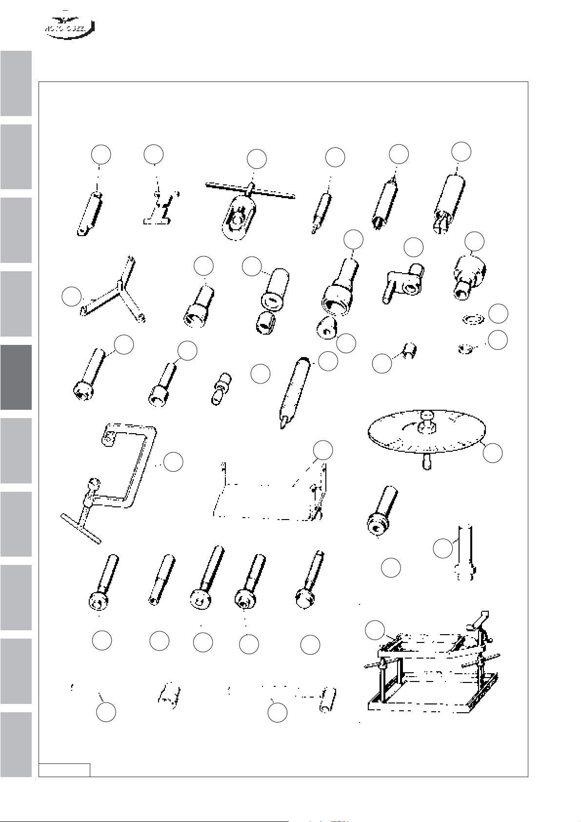
Fig. 05-01
2
ATTREZZATURA SPECIFICA E COPPIE DI SERRAGGIO
SPECIFIC TOOLS AND TIGHTENING TORQUES

Pos. N. Codice Denominazione
Part. number
1 19 92 73 00 Bussola per montaggio anello di tenuta sull’albe-
ro secondario
2 19 92 72 20 Attrezzo per montaggio anello di tenuta sul co-
perchio distribuzione (albero motore)
3 10 90 72 00 Attrezzo per smontaggio e montaggio valvole
4 19 92 61 00 Punzone per anello di tenuta pignone coppia co-
nica
5 19 92 88 00 Attrezzo premontaggio allineamento coppia co-
nica
6 19 92 94 00 Punzone per cuscinetto albero frizione sulla sca-
tola
7 19 92 60 00 Punzone per anello tenuta scatola trasmissione
8 19 90 59 00 Punzone per anello tenuta sull’albero frizione
9 19 92 72 00 Punzone per montaggio anello di tenuta sul co-
perchio scatola cambio per albero secondario
10 19 90 65 00 Attrezzo montaggio e centraddio disco frizione
11 19 91 18 00 Attrezzo tenuta volano
12 19 92 72 02 Distanziale per montaggio anello sull’albero se-
condario
13 19 90 70 00 Estrattore anello interno sul perno forato
14 19 92 75 00 Estrattore anello esterno cuscinetto scatola tra-
smissione
15 19 92 62 00 Punzone per cuscinetto sul pignone coppia coni-
ca
16 19 92 77 00 Attrezzo tenuta ingranaggio rinvio per smontaggio
cambio
17 19 92 63 00 Punzone per cuscinetto albero primario sulla sca-
tola cambio
18 19 92 64 00 Punzone per anello esterno cuscinetto conico sul
corpo porta pignone coppia conica
19 19 92 65 00 Punzone per anello esterno del cuscinetto sca-
tola trasmissione
20 19 92 76 00 Estrattore per cuscinetto porta braccio oscillante
sul coperchio scatola cambio
21 19 92 78 00 Bussola di riduzione per attrezzo smontaggio
valvole (tale attrezzo porta il N. 10 90 72 00)
22 19 92 79 00 Punzone per pressare l’anello interno del cusci-
netto sul perno forato
23 12 91 20 00 Attrezzo montaggio anello di tenuta sull’albero
motore lato volano
24 19 92 71 00 Punzone per pressare l’anello di tenuta sulla
flangia e albero motore lato volano
25 18 91 24 50 Supporto motore (è adattabile montando un qua-
dretto di legno od altro materiale)
26 14 92 69 00 Attrezzo controllo livellatura galleggianti dei car-
buratori
27 19 90 25 00 Supporto scatola cambio
28 19 92 96 00 Disco graduato
29 19 92 60 20 Punzone montaggio cappellotto su guida valvole
30 19 92 73 20 Attrezzo per montaggio anello di tenuta sul co-
perchio distribuzione (albero a camme)
31 19 92 64 60 Introduttore pista esterna cuscinetto albero se-
condario
32 19 90 54 60 Chiave tenuta dado per albero frizione
33 19 90 71 60 Attrezzo di tenuta albero frizione
Designation
Bush for fitting oil seal on secondary shaft
Tool for fitting oil seal on timing cover (crankshaft)
Valves disassembly / assembly tool
Punch for bevel gear pair pinion oil seal
Bevel gear pair alignment preassembly tool
Punch for clutch shaft bearing on case
Punch for transmission case oil seal
Punch for clutch shaft oil seal
Punch for assembling oil seal on gearbox cover
for secondary shaft
Clutch disk assembly and centring tool
Flywheel holder tool
Spacer for installation of ring on secondary
shaft
Puller for internal ring on hollow shaft
Puller for transmission case bearing external
ring
Punch for bearing on bevel gear pair pinion
Intermediate gear holding tool for removal of
gearbox
Punch for primary shaft bearing on gearbox
Punch for conical bearing external ring on bevel
gear pair pinion holder body
Punch for transmission case bearing outer ring
Puller for swinging arm holder bearing on gearbox cover
Reducer bush for valve disassembly tool (this
tool is marked with No. 10 90 72 00)
Punch for driving internal bearing ring on hollow
shaft
Tool for assembling oil seal on crankshaft - flywheel side
Punch for driving oil seal on flange and crankshaft – flywheel side
Engine stand (can be adapted by installing a
block made of wood or other material)
Carburettor floats level check tool
Gearbox support
Graduated disk
Punch for mounting cap on valve guide
Tool for assembling oil seal to timing cover
(camshaft)
Secondary shaft bearing outer race inserter tool
Clutch shaft nut holding wrench
Clutch shaft holding tool
1
2
3
4
5
6
7
8
9
10
ATTREZZATURA SPECIFICA E COPPIE DI SERRAGGIO
SPECIFIC TOOLS AND TIGHTENING TORQUES
3

2 COPPIE DI SERRAGGIO
1
2
3
4
5
6
7
8
9
Denominazione Coppia di serraggio
(Nm)
Teste cilindri
Viti di fissaggio coperchi teste motore 10
Fissaggio candele accensione 20÷30
Basamento e coperchi
Dado fissaggio teste-cilindri al basamento (M 10) 40÷42
Dado fissaggio teste-cilindri al basamento (M 10) 28÷30
Dadi unione basamenti (M 8) 22÷25
Dadi unione basamenti (M 10) 38÷40
Viti di fissaggio coperchio distribuzione 10
Viti fissaggio coppa olio 10
Imbiellaggio
Dado autobloccante fissaggio cappelli alle bielle 30÷32
Viti fissaggio volano all’albero motore 40
Viti fissaggio corona dentata 10
Distribuzione
Raccordo fissaggio albero camme al basamento 30
Viti fissaggio ingranaggio sull’albero a camme 25÷27
Avviamento elettrico
Viti di fissaggio motorino avviamento 30
Alimentazione
Viti di fissaggio pipe aspirazione alle teste 10
Lubrificazione
Viti fissaggio pompa olio al basamento 10
Vite fissaggio coperchietto tenuta cartuccia filtrante 25
Accensione
Viti fissaggio statore del generatore 5
Viti fissaggio rotore del generatore 32÷35
Frizione
Dado fissaggio albero frizione 100
Cambio velocità
Dadi bloccaggio albero primario 100
Viti fissaggio coperchio alla scatola cambio 10
Viti fissaggio scatola cambio al coperchio campana frizione 10
Parti collegamento motore
Dado per tirante anteriore 45
Dado per viti lunghe e corte 45
Viti fissaggio coperchio campana frizione al motore 25÷30
Trasmissione posteriore
Dado bloccaggio pignone conico alla custodia 10
Viti fissaggio corona conica al perno forato 42
Viti fissaggio coperchio alla scatola trasmissione 25
Telaio
Viti fissaggio, semi culla, culla telaio 45
Viti fissaggio cavalletto centrale 23
Sospensione anteriore
Viti fissaggio testa della forcella 45
Viti fissaggio base della forcella 45
Viti fissaggio gambale al perno ruota 10
Sospensioni posteriori
Viti fissaggio sospensioni posteriori parte superiore e inferiore 23
Ruota anteriore e disco freno
Perno ruota 80
Viti fissaggio disco freno al mozzo 23
10
4
ATTREZZATURA SPECIFICA E COPPIE DI SERRAGGIO
SPECIFIC TOOLS AND TIGHTENING TORQUES
 Loading...