

MOTO GUZZI 700 cc Twin V-7 Riders Manual
~
MOTOGUZZI
rider's handbook
~
MOTO
GUZZI
FACTORY
AND
OFFICES:
Meodello dItI
urio
(Como)
VI,
ElNnue'-
V.
Parod
i,
57
Telephones:
.¥..ndello
~I
lario
71
.112
(4
lines)
Telegram5:
MOTOGUUI • Mar'ld&llo Lorio
HEAD
OFFICE:
Vi,
Andegarl, ..
felephone:
890632
BRANCH OFFICE:
Mil,,"
Vi,
Domodossola,
17
Telephone: 311.105
Nlpl
...
Piana
MuniciplQ,
8"
Telephone: 310.581
Telegraml: MOTOGUUI _ Naples
700
cc
TWIN
v
-
7
MODEL
RIDER'S
HANDBOOK
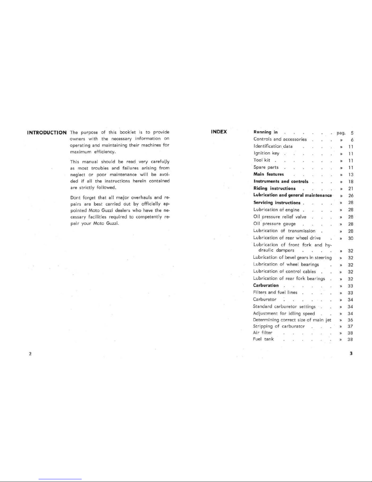
INTRODUCTION The
purpose
of this booklet
is
to
provide
ownen
with the necessary information on
operating
and
maintaining
their
machines for
maximum efficiency.
2
This manual should
be
read very carefully
as most troubles
and
fail
urn
arising from
neglec;t
or
poor
maintenance will be avoi-
ded
if
all the instructions herein contained
are
strictly followed.
Dont
forget
thai
all
major
overhauls
and
re-
pairs
are
best carried
out
by officially ap-
pointed Mota Guzzi dealers
who
have the ne·
cessary
facilities required to competently re-
pai r your Moto GUlli.
INDEX Running
in
Controls
and
accessories
Identification
data
Igni
tion key
Tool kit
Spare
parts
Main features
Instruments
ilnd controls
Riding
instructions
Lubrication
and
genenl
milinten
.. nce
Servicing
instruct
ions .
Lubrication of engine
Oil pressure relief valve
Oil
pressure
gauge
Lubrication
of
transmission
Lubrication
of
rear
wheel drive
Lubrication of front f
ork
and
hy_
draulic
dampers
lubrication
of
bevel gears
in
steering
Lubrication of wheel bearings
Lubrication of control
cables
Lubrication
of
rear
fork bearings
C
..
rburation
Filters
and
fuel lines
Carburetor
Standard
carburetor
settings
Adjustment for idling
speed
Determining correct size of main jet
Stripping
of
carburalor
Air filter
Fuel
tank
pag. 5
• 6
•
II
•
II
•
II
•
II
•
13
•
18
•
21
• 26
• 28
• 28
• 28
• 28
• 28
• 30
• 32
• 32
• 32
• 32
• 32
• 33
• 33
• 34
•
34
•
34
• 36
•
37
•
38
• 38
3
,
Mufflers
Valve gearing
Ta.ppet ciea.rance
Valve
tim
ing
Ignition
Distr
ibutor
Spark
plugs
Ignition timing
Adjus
tment
s
Generator
belt
Clutch lever
Steering
Front
brake
lever
Rear
brake
pedal
Rear suspension units
Removal of
front
wheel
Removal
of
rear
wheel
El
eclriCilI equipme
nt
Battery
Generator
Regulator unit
Starter
motor
H
orn
Light switch,
dipper
switch
and
horn
button
Headlight
Bulbs
Tail light
Fuses
Cables
pag. 39
Running
in
•
39
•
39
• '0
· "
· "
· "
· "
•
45
•
45
•
45
•
45
•
46
· "
•
'9
• 50
• 51
•
5d
• 5d
• 55
•
55
•
55
•
56
•
56
•
56
•
56
•
56
•
56
•
56
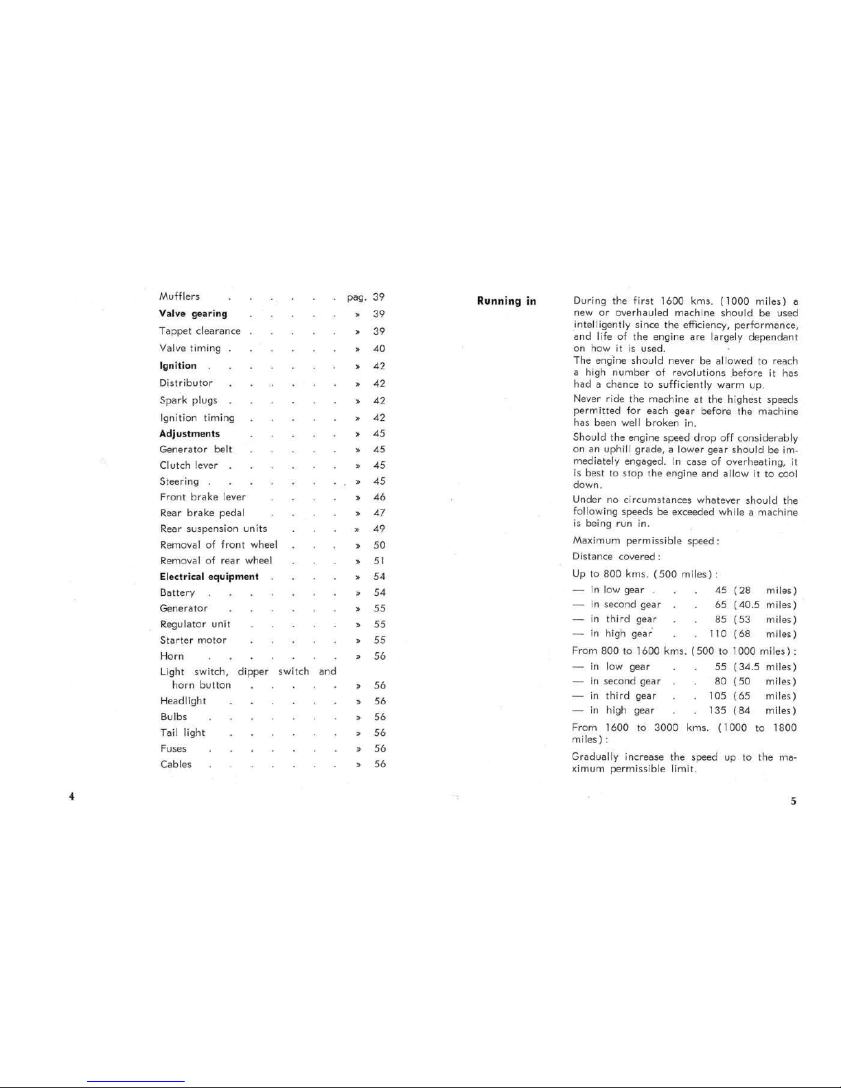
During
the
first
1600
kms.
(1000
miles)
a
new
or
overhauled
machine
should
be used
intelligently since the efficiency,
performance,
a.nd
life
of
the engine are largely
dependant
on how
it
is
used.
The englne
should
never be allowed to reach
a high
number
of
revolutions before
it
has
had
a chance to sufficiently
warm
up.
Never ride the machine
at
the highest speeds
permitted
for each
gear
before the machine
has been
well broken in.
Should the engine speed
drop
off considerably
on an
uphill grade, a lower gear
should
be im.
mediately engaged.
In
case of overheating,
it
is
best
to
stop
the engine and allow it
to
cool
down.
Under
no
circumstances
whatever should the
Following speeds be exceeded while a machine
is
being run in.
Maximum permissible
speed:
Distance
covered:
Up
to
800
kms.
(500
miles) :
in
low gear
in
second
gear
in
third
gear
45
(28
miles)
65
(40.5
miles)
85
(53
miles)
in
high
gear
110 (68
miles)
From
800
to
1600
kms.
(500
to
1000
miles)
:
in
low gear
55
(34.5
miles)
in
second gear
80
(50
miles)
in
third
gear
IDS
(65
miles)
in
high gear 135
(84
miles)
From
1600 to
3000
kms.
(1000
to
1800
miles) :
Gradually increase the speed
up
to
the ma-
ximum
permissible limit.
5

After the
first
500
kms
.
(
300
miles )
Ev
ery
500 kms.
(
300
miles)
Change the engine oil.
Tighten all nvts
and
bolts.
Check valve clearance.
Check
distributor
contacts gap.
Check oil level. Correct level
is
in
between
the
minimum
and
maximum
mark
on the
Filler
cap
dipstick.
CONTROLS AND ACCESSORIES
(See fig.
I)
,
I Front
brake
lever
2
Air control lever
3
Throttle control grip
4 Fuel filler cap
5
Gearshift lever
6
Pillion footrests
7 Pillion handgrip
8
Headlight
9
Speedometer
and
lighted indicators
JO
Key
type ignition switch
II
Clutch lever
J2
Dipper switch
il
nd horn
button
J3
Side stilnd
14 Reilr brilke pedill
IS
Footrests
16 Center
stand
17 Tail lamp
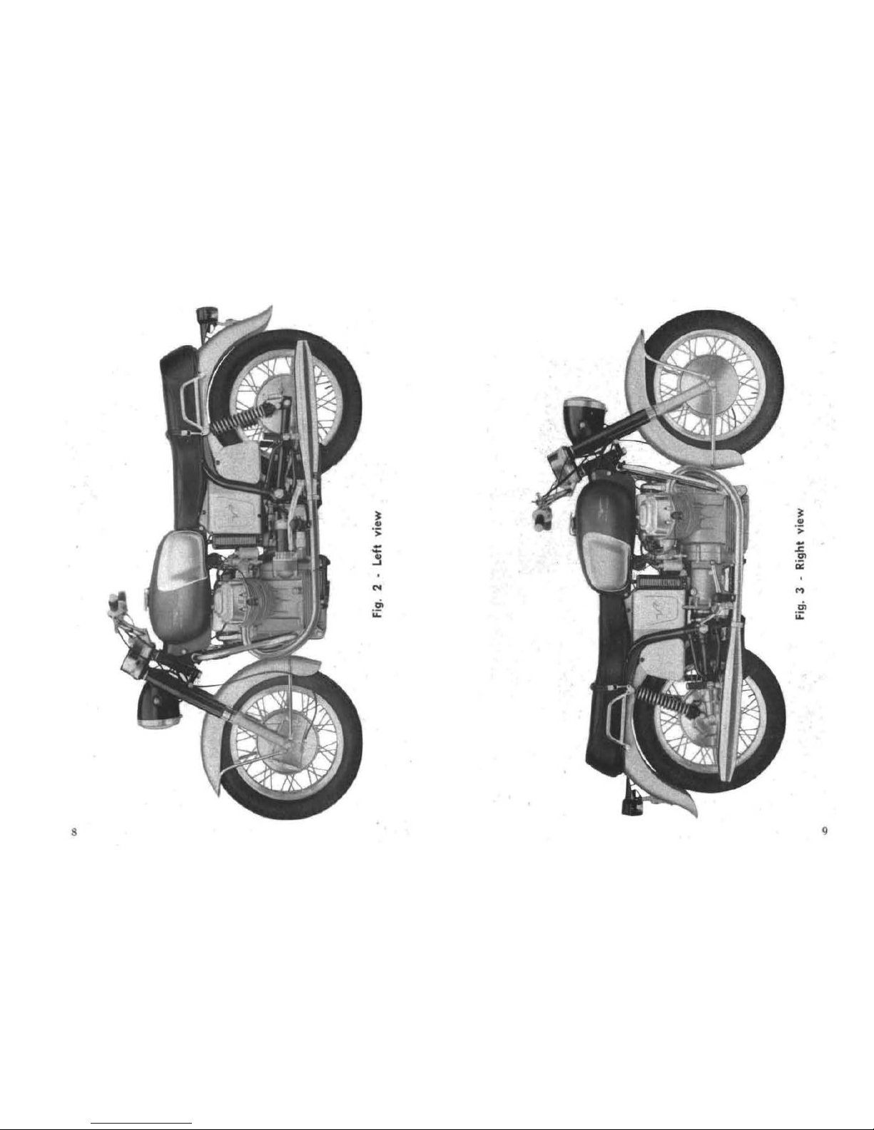
N.B. _ The te
rm,
.. right
It
an
d " le
fl
It
in the
lui
a
..
Ul
ed
in
11M
o.e
nH
th
ey would op
pea
r to
On
e
l illing
in
the .... ddl
e.
fig . 1
7
•
•
. !
•
•
.>
-
-
-
•
~
~
~
"
N
..,
..
;;:
..
;;:
8
9
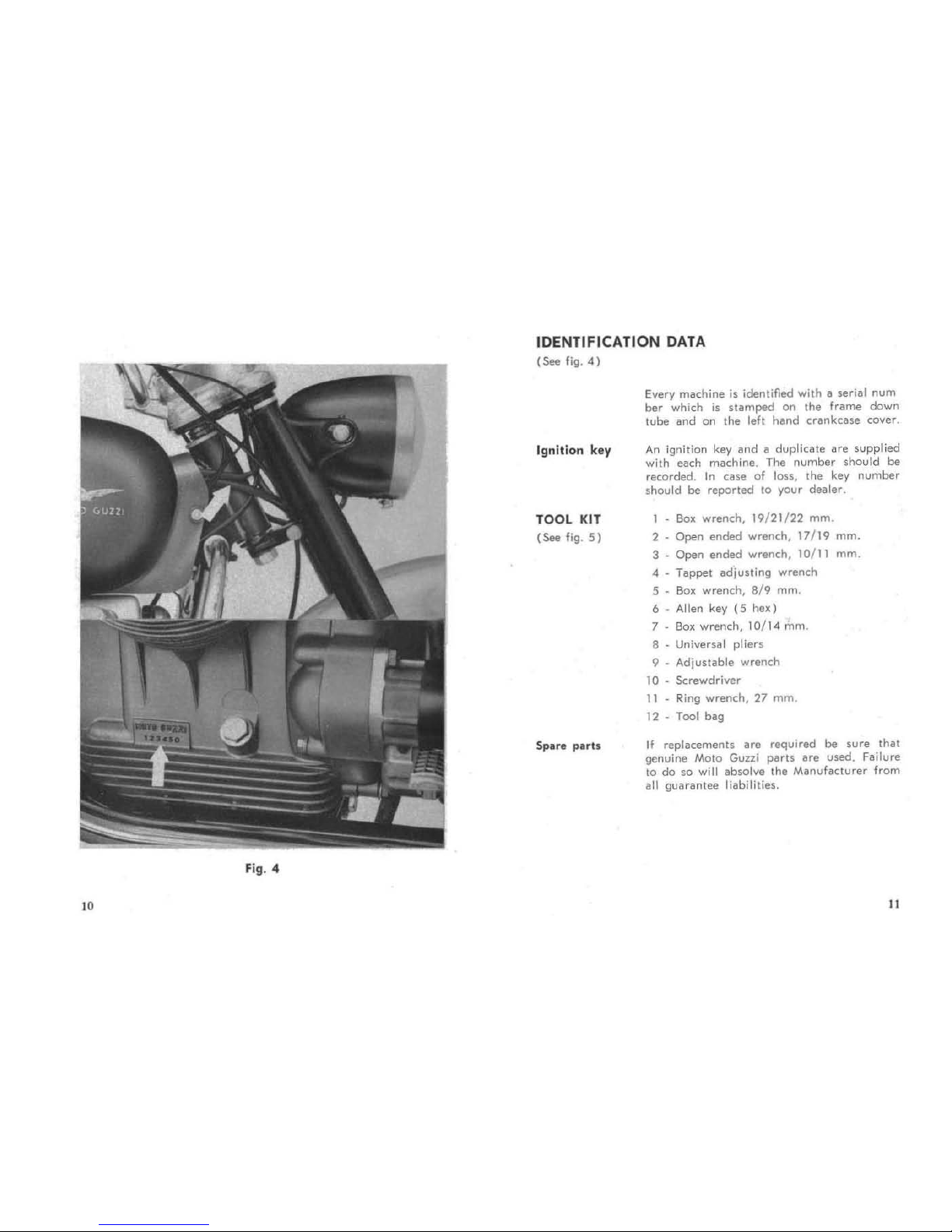
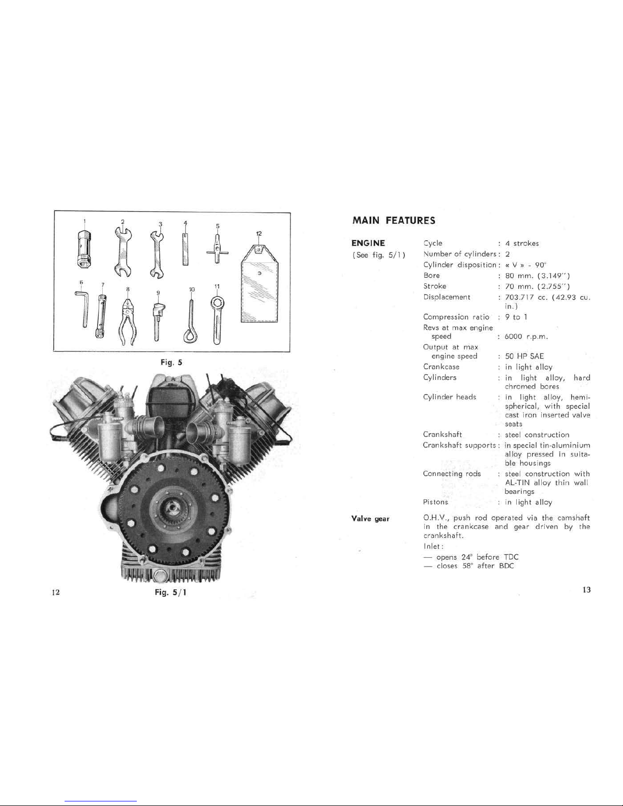
Fig. 4
10
IDENTIFICATION
DATA
(See
fig.
4)
Ignition key
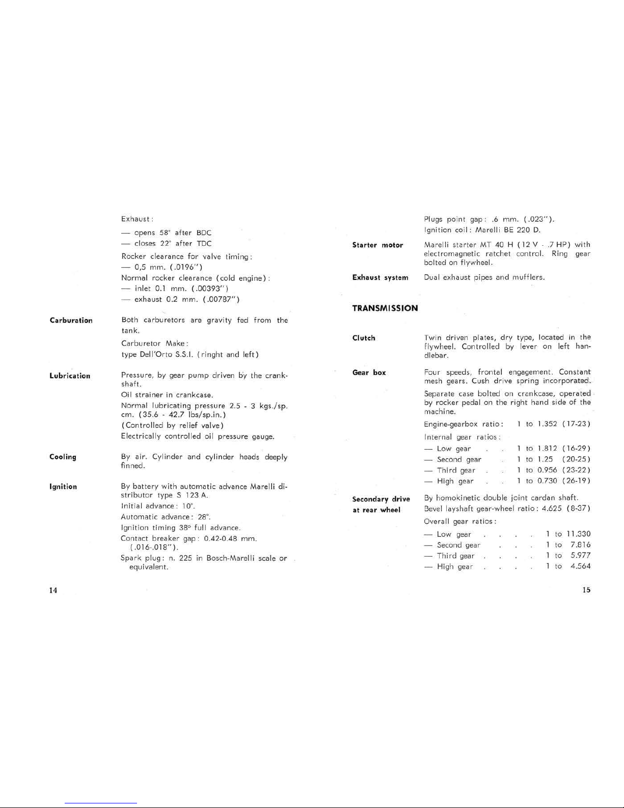
TOOL KIT
(See
fig.
5)
SpOU
$ pllTt$
Every
machine
is
identified with ill serial
num
ber
which
is
stamped
on the frame down
lube
and
on the left
hand
crankcase
cover.
An
ignition
key and
II
duplicllte
are
supplied
with each machine, The
number
should
be
recorded.
In
case of
lou,
the
key
number
should
be
reported
10
your dealer.
1
~
So)!.
wrench, 19/21/ 22
mm
.
2
Open
ended
wrench, 17/ 19
mm.
3
Open
ended
wrench, 10/
11
mm.
4
Tappel
adjus
ting wrench
5
Box wr
ench,
8/9
Mm.
6
Allen key
(5
hex)
7
Box
wrench, 10/1 4 Mm.
,
Universal
pliers
9
Adjustable
wrench
10
Screwdriver
11
Ring wrench, 27
Mm.
12
- Tool bag
If
replaceme
nts
are
required
be
sure
thaI
genuine
Moto
GUlzi
paru
iJre
used.
Failure
to do so will absolve the Manufllctvrer fr
om
all guarantee liabilities.
"
Fi
g. 5
12
Fig
. 5/ 1
MAIN
FEATURES
ENGINE
(See
fig.
5/1)
Valva gear
Cycle 4
strokes
Number
of
cylinders
: 2
Cylinder
disposition:
«V
• . 90"
Bore
80
mm.
(3.149")
Stroke
Displacement
70
mm.
(2.755")
703.717
CCo
(42.93
cu.
in.)
Compression
ratio
9
to
1
Revs
at
max engine
speed 6000 r .p.m.
Output
at
max
engine
speed
50
HP
SAE
Crankcase
Cylinders
Cylinder heads
in
light alloy
in
light
alloy,
hard
chromed bores
in
light
alloy, hemi-
spherical,
with
special
cast
iron
inserted
valve
seats
Crankshaft
steel
construc
tion
Crankshaft
supports: in
special
lin-aluminium
Conne<:ting
rods
Pistons
alloy
pressed
in
suita-
ble housings
steel
construction
with
AL·TIN
alloy
thin
wall
bearings
in light
alloy
O.H.V.,
push
rod
operated
via
the
camshaft
in the crankCi,lse
and
gear
driven
by
the
cr.,nkshaft.
Inlet;
opens
24'
before
TDC
- closes 58"
.,fter
SDC
13
Carburation
Lubrication
Cooling
Ignitio
n
14
Exhaust :
-
opens
58· after
BDC
- closes 22·
after
TOC
Rocker clearam:e for valve
timing:
- 0,5 mm.
(.0196")
Normal rocker clearance
(cold
engine)
:
in
let
0.1
mm.
(.00393")
- exhaust 0.2 mm.
(.00787")
Both
carburetors
are gravity fed
from the
tank.
Carburetor
Make:
type Dell"Orto
5.5.1.
(ringht and
left)
Pressure,
by
gear
pump
driven by the crank-
shaft.
Oil
strainer
in
crankcase.
Normal lubricating
pressure
2.5 - 3
kgs./sp.
crn.
(35.6·
42.7
Ibs/sp.in.)
(Controlled by relief valve)
Electrically controlled oil
pressure
gauge.
By
air
. Cylinder
and
cylinder heads deeply
finned.
8y
battery
with
automatic
advance Marelli di-
stributor
type 5 123
A.
Inilial
advance: 10·.
Automatic
advance:
28°.
Ignition
timing 38" full advance.
Contact
breaker
gap:
0.42-0.48 mm.
(
.016-.018").
Spark
plug : n. 225
in
Bosch-Marelli scale
or
equivalent.
Exhau
st
system
TRANSMISSION
Clutch
Gear
box
Seconda
ry
drive
at
rear
wheel
Plugs point gap : .6 mm. (.
023")
.
Ignition
coil: Marelli
BE
220
O.
Marelli
stuter
MT
40 H
(12 V-.7 HP) with
electromagnetic ratchet control. Ring gear
bolted on
flywheel.
Dual
e~haust
pipes
and
mufflers.
Twin driven plates,
dry
type, located
in
the
flywheel. Controlled by lever on left handlebar.
Four speeds, frontal engagement. Constant
mesh gears. Cush drive spring
incorpor<Hed.
Separate case bolted on crilnkcase,
operated
by rocker
pedal
on
the right hand side of the
machine.
Engine-gearbox
ratio:
I to 1.352
( 17-23)
Internal gear
ratios:
Low
gear
'0
1.812 ( 16-29)
Second gear
w
1.25
(20-25)
Third gear w
0.956
(23-22)
High gear
'0
0.730
(26-19
)
By
homokinetic double joint
cardan
shaft.
Bevel layshafl gear-wheel
ratio:
4.625
(8·37)
Overall gear ralios :
Low
gear
'0
11.330
Second gear
'0
7.816
Third gear
'0
5.977
High gear
'0
4.564
15
FRAME
Tires
Tire
prenure
Oyer~dl
dimensio ns and
weight
Pe
rforman
ce
16
Duplex cradle,
tubular
5!ruclure.
Telescopic front
forI<
incorporating hydraulic
dampen.
Rear swinging fork with external
adjustable
springs.
4.00 x 18 front
and
rear, block type
0:
high
speed
".
Front:
solo rider kgs./sq.cm. 1.5
(21
Ibs/sq.in.)
with pillion
..
1.5 (21
Ibs/s
q,in
.)
rolo
rider
..
1.8
(26
Ibs/sq.in.)
with pillion
..
2.0
(29Ibs/sq.in.)
Twin leading shoes eJlpanding type front
bra·
ke
operated
by
hand
lever
on
the
right han.
dlebar.
Large rellr
brake
operated
by pedal
on
leff
hand
side
of
machine.
Wheelbll5e
1.445
Length
2.230
Width 0.795
Height
(dry)
1.050
- Minimum
ground
clearance.
0.150
Dry
weight
mlS. ( ab!.
56.9")
mls.
(ab!. 87.8
" )
mts.
(ab!.
31.2")
mts.
(abl. 40.3")
mlS.
(ab!.
5.9")
.
490
Lbs.
Maximum permissible speeds
and
gradients
climable
in
each gear, solo
riding:
Low
gear ab!. 66
kms
/h
41
m.p
.h.)
Climbing ability 60%
Second gear
..
96
kms/h
59.6
m.p.h.)
Climbing ability
34%
Third gear • 120
kms/h
74.5
m.p.h.)
Climbing ability 23 %
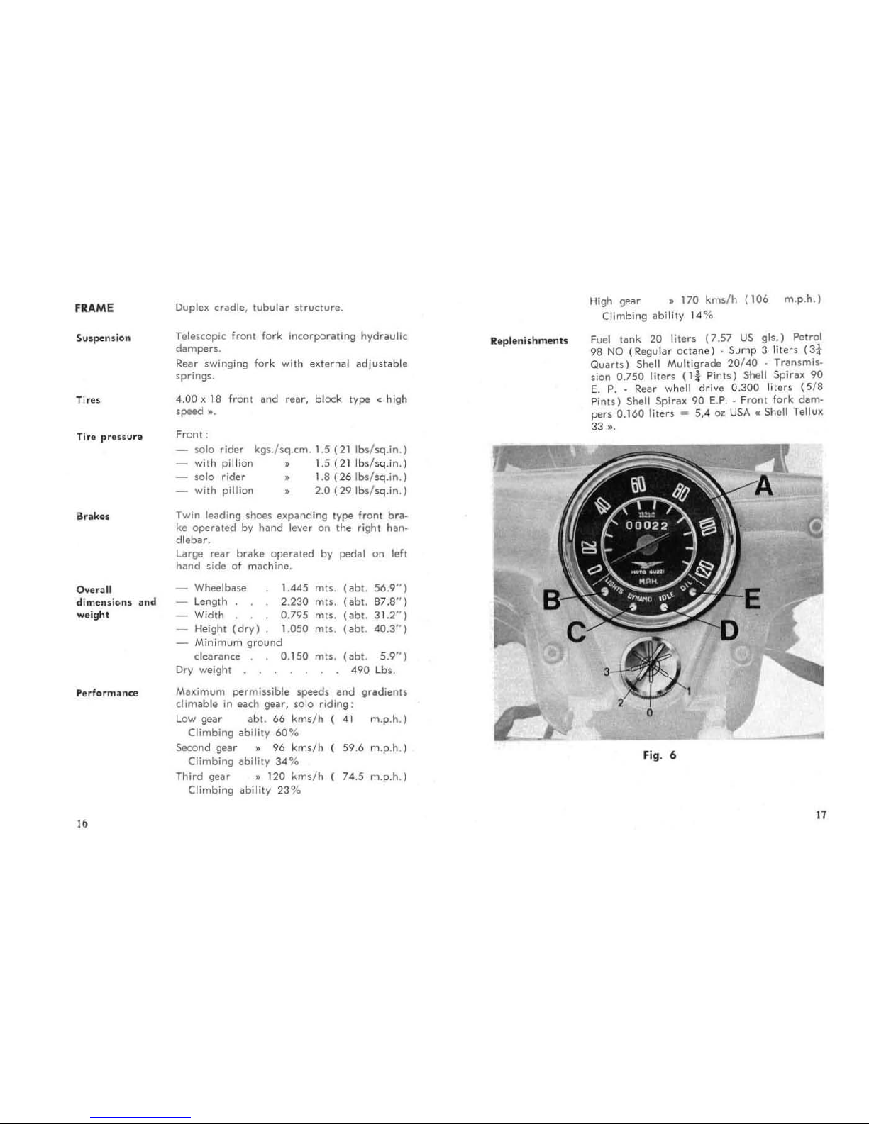
Reple
nishmen
ts
High gear
• 170
kms/h
(106
m.p.h.)
Climbing ability 14%
Fuel
tank
20 liters
(7.57
US
gls.)
Petrol
98
NO
(Regular
octane) . Sump
3 liters
(3*
Quarts)
Shell Multigrade
20/40 . Transmh·
sion 0.750 liters
(Ii
Pints)
Shell
Spiru
90
E.
P
..
Rear whell drive
0.300
liters
(5/8
P
ints)
Shell Spirax 90 E.P
.. Fron
t fork
dam.
pen
0.160
liters
= 5,4 0%
USA
c Shell Tellux
33
•.
d
Fig
. 6
17
 Loading...