

Page 1

0
Operating and installation guide
digital control device m.unit blue
valid from serial no. 000xxxxx
(see the serial sticker at the device)
Suchen Sie die deutsche Bedienungsanleitung?
http://motogadget.com/de/elektrik/elektronische-steuerbox-m-unit/downloads.html
_______________________________________________________________
Manual V1.3
Page 2

1
CAUTION !
THIS PRODUCT OPERATES ON STRONG CURRENTS
.
CONNECTION FAILURE MAY LEAD TO CABLE FIRE OR
EXPLOSION OF VEHICLE’S BATTERY. THERE IS
A RISK OF
SERIOUS OR LETHAL INJURIES.
IF YOU ARE NOT A CERTIFIED MOTORCYCLE TECHNICIAN
PLEASE STOP HERE AND ASK YOUR LOCAL MOTORCYCLE
SHOP FOR PROFESSIONAL INSTALLATION!
SEMICONDUCTOR SWITCHES IN USE! MEASURED V
OLTAGES
AT TERMINALS ARE NOT SUITABLE TO DIAGNOS
E A FAILURE
OR DEFECT.
MOUNTING ON UNEVEN FACES WILL CRACK THE
HOUSING
AND CAUSE A FAILURE.
Thank you very much for purchasing a high quality product by motogadget.
Please read the following information and recommendations thoroughly and
follow these instructions during installation and use of the instrument. No
liability is assumed by motogadget for damage or defects resulting from
negligence or failure to follow the operating and installation guide.
Please read the instructions below thoroughly and follow their advice when
handling your device. Warranty or liability claims to motogadget for damages
resulting from non-compliance with this manual will be null and void.
Find more product informations:
http://motogadget.com/en/electrics/electronic-control-box-m-unit/downloads.html
Contact:
motogadget GmbH
Köpenicker Str. 145
D - 10997 Berlin
Germany
Tel. +40 (0)30-6900410-0
www.motogadget.de
info@motogadget.de
© Copyright and all rights by motogadget GmbH, Berlin 2009-2016
motogadget and m-Unit are registered trademarks of motogadget GmbH, Berlin, Germany
Page 3

2
1 Review Of Delivery
All products from motogadget are thoroughly checked to ensure they are completely fault free
when dispatched. Please check the received goods immediately for possible transport damage. If
you find any damage or other deficiencies, please contact us immediately.
In this regard we refer to our general terms of business and delivery, which are published under
www.motogadget.com. Should a return of the received delivery be agreed, please note that we
only take back goods in their original packaging. The instrument and its accessories must be
returned within the legal period of time and without any traces of use. We do not assume any
liability for returns which are insufficiently insured or packed.
2 Exclusion Of Liability
THE M-UNIT OPERATES STRONG CURRENTS. CONNECTION FAILURE MAY LEAD TO
CABLE FIRE OR EXPLOSION OF VEHICLES BATTERY. THERE IS A RISK OF HEAVY OR
LETHAL INJURIES. THE DEVICE AND ITS ACCESSORIES MUST BE INSTALLED BY A
CERTIFIED MOTORCYCLE TECHNICAN AND IN AN AUTHORIZED SERVICE CENTER.
IN CASE OF REVERSE POLARITY OR VOLTAGE ABOVE 24V M-UNIT CAN BE DAMAGED.
THE DEVICE HAS TO BE REPLACED AND ALL WARRANTY CLAIMS BECOME INVALID.
DEVICE HOUSINGS AND ALL OTHER DELIVERED PARTS MUST NOT BE OPENED OR
DISMANTLED. IN CASE OF NON-COMPLIANCE ALL WARRANTY CLAIMS BECOME
INVALID. THE USE OF THE DELIVERED DEVICE AND ITS ACCESSORIES FOR RACING OR
OTHER COMPETITIONS, AS WELL AS ALL USES THAT DO NOT CORRESPOND TO THE
RECOMMENDED APPLICATION RENDER ALL WARRANTY CLAIMS INVALID.
MOTOGADGET ACCEPTS NO LIABILITY FOR DIRECT OR INDIRECT DAMAGE OR
SUBSEQUENT DAMAGE OF ANY KIND RESULTING FROM THE USE, INSTALLATION OR
CONNECTION OF THE DEVICE OR OTHER DELIVERED EQUIPMENT. THIS EXCLUSION OF
LIABILITY PARTICULARLY INCLUDES DAMAGE TO PERSONS, MATERIAL LOSSES AND
FINANCIAL DAMAGES. THE USE IN AREAS OF PUBLIC TRAFFIC IS UNDERTAKEN AT THE
USER'S OWN RISK.
3 Safety Instructions
• PRIOR ELECTRICAL CONNECTION OF THE DEVICE AND GENERALLY PRIOR TO ANY
WORK AT THE VEHICLES ELECTRICAL SYSTEM BATTERY MUST BE DISCONNECTED
COMPLETELY. THEREFORE KEEP THIS ORDER: DISCONNECT AT FIRST THE
NEGATIVE TERMINAL AND THEN THE POSITIVE TERMINAL. FOR THE
RECONNECTION ACT IN THE REVERSE ORDER.
USE OF M-UNIT TO VEHICLES WITH PLUS POLE TO VEHICLE FRAME (OLDER
ENGLISH MOTORCYCLES) IS NOT POSSIBLE.
• INSTALLATION AND ELECTRICAL CONNECTION OF THE M-UNIT HAS TO BE
CARRIED OUT BY A CERTIFIED MOTORCYCLE TECHNICIAN ONLY.
• ALL CABLE DIAMETERS MUST BE DIMENSIONED ACCORDING THE CURRENT FLOW.
THE CABLE DIAMETERS MUST NOT GO BELOW THE VALUES LISTED IN CHAPTER
8.5. CURRENT FLOW OF CONNECTED LOADS MUST NOT EXCEED THE VALUES
LISTED IN CHAPTER 8.5
• THE CABLE ENDS TO M-UNIT’S CONNECTION TERMINAL MUST BE CRIMPED WITH
CABLE END SLEEVES. THEREFORE USE A SUITABLE CRIMPING TOOL.
• ALL ELECTRICAL CONNECTIONS IN THE WIRING LOOM AND AT THE CONNECTION
TERMINALS HAVE TO BE CARRIED OUT IN A PROPER WAY. FAILURES AT
CONNECTING JOINTS MAY CAUSE A CONTACT RESISTANCE AND MAY LEAD TO
HEAT GENERATION DURING HIGH CURRENT FLOW. THERE IS A RISK OF SERIOUS
OR LETHAL INJURIES.
Page 4
3
• THE DEVICE WILL BECOME DAMAGED BEYOND REPAIR IF A BATTERY CABLE IS
DISCONNECTED WHILE THE RUNS (LOOSE OR WORN CONTACT ETC.). PLEASE
MAKE SURE THAT THE VEHICLE’S BATTERY IS CONNECTED CORRECTLY AND THAT
THE CONNECTOR CABLES ARE FIXED TIGHTLY.
4 Duty Of Registration
The m.unit blue does not have to be registered. The user has the responsibility that chosen
settings for vehicles rear and brake light are conform to the country laws. The user also has to
ensure compliance with local regulation in respect to connection and usage.
5 Technical Data And Functions
5.1 General Data
length / width / depth 90 / 53 / 30 mm
weight 110 g
threaded fastening bores 2 x M5, bore spacing 74 mm
standby current approx. 450 µA
operating voltage 6 – 18V , suitable for 12V electrical systems
operating temperature -20°... + 80°C
input circuits 12
output circuits 10 (START and AUX2 with 2 wire terminals each)
display 23 internal LED
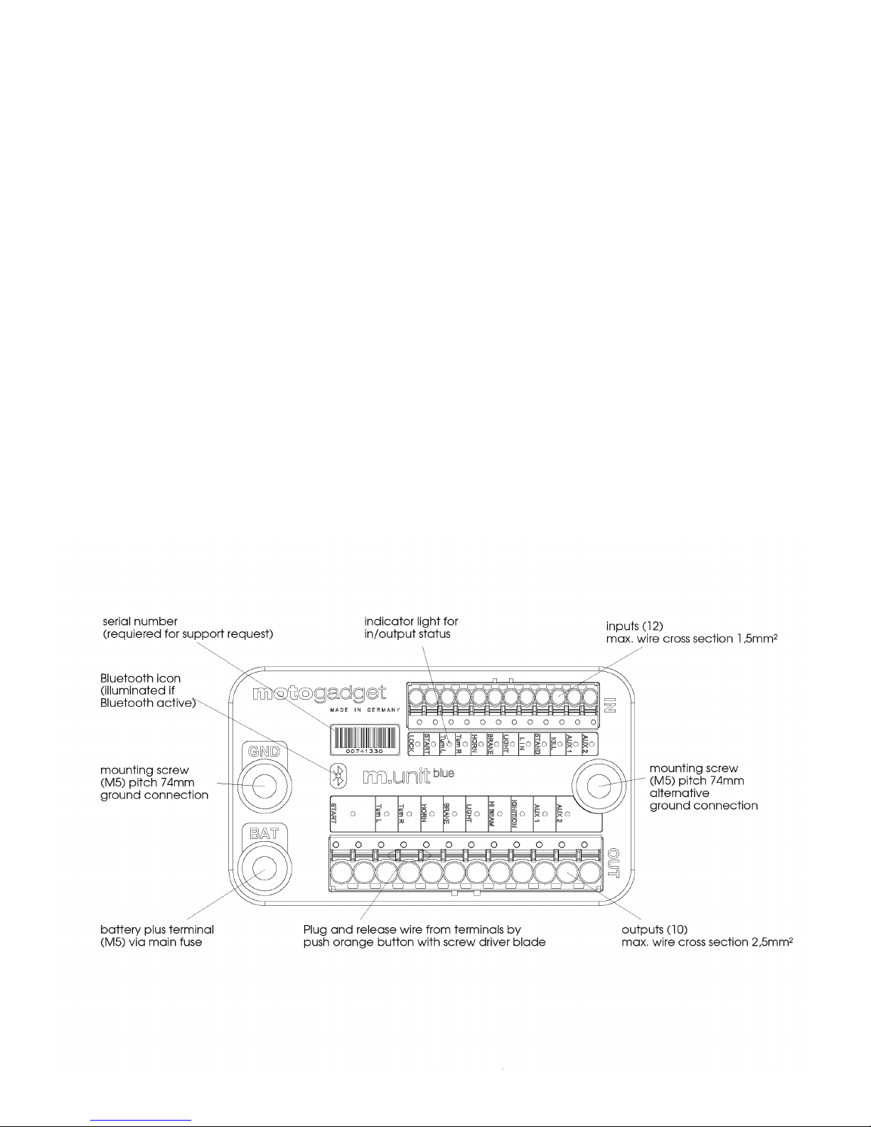
5.2. Overview
Page 5

4
6 Functions And Operation
The m-Unit is able to act as central control unit in the vehicle’s electrical system. It provides
following features:
Without smart phone:
• Complete digital push button control unit; optional 4 or 5 push button operation
• complete replacement of all OEM fuses 10 independent circuits are digitally supervised; a
circuit will be shut down in case of interferences after removing the interference, the safety
feature will be reset automatically
• integrated, digital, load-independent flasher relay; with programmable switch-off feature
(optional), selectable m-Wave mode
• turn signal setting for use as position light
• parking light, headlight flasher
• integrated digital brake-light modulator with programmable flashing sequence, acceleration-
controlled emergency brake-light
• pairing of m-unit with other motogadget products via LIN bus
• integrated starter relay for solenoid switch (up to 30A switching capacity)
• smart and fully configurable load control / shut-off for maximum starting power of battery on
starting process
• low beam and high beam control (up to 200W switching power) using just one push button
• integrated digital horn relay
• integrated position-independent alarm system
• integrated hazard light feature
• diagnostic feature for layout of input, output, circuit switching status, diagnosis of short-circuits
etc.
• two fully configurable auxiliary outputs AUX1 and AUX2
Pairing of m-unit with your smart phone via Bluetooth in combination with our „m.garage“
app providing advanced functionality:
• Pairing via Bluetooth LE (Low Energy); therefore extremely low power consumption of vehicle
and smart phone cell
• reporting of alarm events (date, time, vehicle „down“ etc.) to smart phone
• real-time analysis of all inputs / outputs, measurements of currents, voltage, temperature
• manual switching of outputs using m.ride app (except starter)
• firmware updates from any location
• configuration of setup menu using m.ride app
• Keyless Go feature using encrypted and secure pairing with your smart phone
• speedometer input is compatible with all standard vehicle speedometer inputs and
automatically calibrates via smart phone GPS
• the m.unit's speedometer input for storage and matching of vehicle's odometer enables for
vehicle management with an overview of maintenance tasks and states of wheels, chain,
brake pads, oils, operating supplies, spark plugs etc.
• logging of states, alarms and maintenance
• fully automatic driver's logbook
• display of parking position and „ping“ feature for locating your vehicle
• calibration and accurate current measurement enable detection of defective LED turn signals
and all standard illuminants
The m.unit is made of a newly designed high-performance thermosetting plastic and resistant to
moisture, heat, cold and vibrations. Microprocessor operated and supervised circuits guarantee
highest reliability. Current flow of each circuit is measured with high accuracy. In case of failure like
a short-circuit the concerning loop will be shut down in a split second. All switching activities are
carried out by state of the art semiconductor switches in a fast, wear-free and almost lossless way.
Page 6

5
Therefore no other devices, relays, boxes or units as part of the wiring harness are necessary. A
complete new and minimised vehicle wiring can be made with minimal time, materials and effort;
compared to conventional solutions, only a fraction of space and cables is needed. State of the art
technology like pulse width modulation afford new possibilities like connecting rear and brake light
together with only one cable. When using m.button, the number of handlebar instruments
connections will be reduced to a single cable by use of our interference-free, proprietary data bus.
The current status of each circuit is shown by an internal LED at the m-unit's topside :
LED off - input not active, output not powered
LED on - input active, output powered – normal condition
short flashing - output shut-down due to short-circuit or overload
Turn Signals
Automatic shut-off can be adjust in setup menu. If this feature is activated a countdown will start
once the signal is flashing. If the adjusted countdown has ended the turn signal stop flashing. The
countdown will stop and set back if the brake is activated. Once the brake is released the
countdown start again with full time length. If a turn signal switch is used and signals has been
automatically shutting down, the switch has to set back to centre prior set the turn signal switch
again to left or right. If two turn signal push button are used is additionally the lane change mode
available. If the button is pressed very shortly the signals will flash only 3 times.
Hazard light
For starting the hazard light hold the push buttons for left and right turn signal for 2 seconds. If a
turn light switch is used, the hazard light function can only be activated if a additional hazard light
switch is activating both turn light inputs at the same time. The hazard light mode will stay active
even if the main (ignition) switch is deactivated.
Light control
In order to save the vehicles battery power the head light is switched off after key lock is switched
on. The head light will be activated automatically after pressing the start button. Further light
control modes can be selected under setup menu no. 8.
If a push button is used for high/low beam control, a short push will toggle between high and low
beam. Holding the button for 2s will switch off the light completely. Pressing the push button again
will switch the low beam light back on. A brief touch of push button is used for headlight flashing.
When using a switch for light control, it's possible to toggle between high and low beam only.
(Please refer to connection scheme.)
The light outputs (Light Hi Out / Light Low Out) can switch 120W each and are designed for a
maximum load of two halogen bulbs with 55W (low beam) and 60W (high beam) respectively.
The parking light has to be activated under setup menu no. 12. The parking light is switched on,
when on turning off the ignition the high beam light is activated. For the parking light feature, there
is no need for an extra illuminant; the feature is realised with the existing illuminant for low beam /
rear light. Parking light activation is signalised by two brief horn sounds. To avoid excessive battery
discharge, please make sure, the parking light is switched on for 2h max.
Kill switch
The running engine can be stopped in three different ways:
a) Double-clicking of engine start button
Pressing the button again after engine stop will crank and start the engine in normal way.
b) Connecting a separate kill switch or push button at the "config" terminal. If a push button is used
the engine is stopped if push button is shortly pressed. To release the kill function hold the button
again for 2 seconds or switch ignition lock off and on again. If a kill switch is used wait for 2
seconds between switching engine off and release the kill switch.
c) When implementing controls with four push-buttons, the engine is killed by pressing the buttons
for light and right turn indicator at the same simultaneously.
Page 7

6
Alarm system
The sensitivity of the alarm system is independent of its positioning and orientation. If activated, the
alarm system will flash all turn indicators when the main switch is deactivated. The vehicle’s
relative position and orientation will be recorded and stored and the alarm system engaged. The
alarm is triggered when the orientation of the vehicle is changed on it’s X, Y or Z axis (e. g. when
the vehicle is raised from it’s kickstand). Depending on the pre-set sensitivity, the alarm will also be
triggered in case of lighter shocks or agitation resp. Depending on the chosen setup, the alarm
system will trigger a pre-alarm and will only activate the alarm when the system is triggered again
in a ten-second time frame.
If the vehicle is transported (e. g. by ferry, trailer or tow-truck) the alarm system can be deactivated
non-recurring by pressing the horn button while switching disengaging the main switch.
If implemented within cars or sidecars, we recommend the highest sensitivity setting (option F).
Keyless Go
The pairing of m.unit and smart phone is a prerequisite of this feature. In the m.ride application, the
feature can be activated / deactivated under „Garage/Fahrzeug_xy/Sicherheit/KeylessGo/aktivieren“ (garage/vehicle_xy/safety/Keyless-Go/activate).
With active feature, the bike will be unlocked with a smart phone distance of less than approx. 4m.
Pressing the start push button will switch on ignition, pressing it again will start the engine. Doubleclicking the button will shut off the running engine, another double-click will shut off the ignition.
When walking away from vehicle, the vehicle will be locked and the alarm system is activated
(provided that it is enabled in setup menu).
Please make sure to carry the ignition key on you, so you can start the vehicle even without
a smart phone.
Speedometer sensor
A speedometer sensor is required for matching the vehicle odometer with the m.garage app. In
case the vehicle is equipped with speedometer sensor, connect the sensor signal cable to AUX2
input, and in setup menu 11, select option A.
In case the speedometer sensor is equipped with two connection cables, connect the ground cable
to vehicle ground connection and the second cable to AUX2 input.
If no speedometer sensor is equipped, please use the provided reed sensor.
For signal detection, mount one
of the provided magnets with glue to one wheel. In this case, the
distance from magnet to wheel axle is irrelevant. Mount the speedometer sensor with a retaining
plate in a way, that the surfaces of magnet and sensor tip are parallelly aligned with a 1mm gap.
The reed sensor tip shall not be flush with the bracket; make sure, it is protruding from the bracket
by approx. 5mm. The bracket may not be made from magnetizable materials (iron, steel etc.), but
shall be made from aluminium, stainless steel or plastics. When driving under load, the distance
between magnet and sensor may not vary! When rotating the wheel, no magnetizable material
(e.g. a steel-made bolt) may pass the sensor tip.
The maximum tightening torque for the sensor mounting nuts is 1 Nm. Please use thread lock
(medium strength) for mounting. Connect the sensor cable to vehicle ground and the second cable
to AUX2 input.
The vehicle speedometer signal is automatically calibrated. Therefore it is required, that the app is
allowed to access the GPS receiver of your smart phone.
Page 8

7
7 Mechanical Installation
Mount the device on a flat surface (metal base plate) free of tension using two M5 screws.
No push or pull force should act to the device. Area of Installation must be protected from
spray water and 30cm away from hot engine or exhaust parts. Maximum ambient temperature
must not exceed +80°C or go below -20°C.
All warranties and extended warranties will be deemed forfeit in case of mechanical damage to the
device.
The m-Unit is connected to vehicle ground by the two mounting screws. Therefore one of
the mounting screws must connected directly to battery minus terminal. The necessary
cable cross section for this connection cable is 1.5mm².
8 Electrical Connection
8.1 General
The device is working in a voltage range between 6 to 18V direct current. Use in vehicles without
battery is not possible.
Make sure that the vehicle is equipped with interference suppressed spark plugs or ignition
cables. The minimum distance between ignition coil or high tension cables and m-Unit must
not be below 30 cm.
8.2 Safety Functions
Currents in the range from 18-40V (e. g. in case of defective controller) will trigger the
activation of the horn. This prevents unnoticed battery cook-off and damage to appliances
due to continued driving.
Loose cables can release currents from 40-80V. In this range, the m-unit activates all
appliances to protect itself. However, the resulting protection is only short term and
prolonged (several seconds) or repeated currents surges will burn out the connected
appliances (e. g. high or low beam light bulbs). When the current surge can no longer be
compensated, burn out occurs and the respective output will become damaged
permanently. Such damage is indicated by the defective/dysfunctional high or low beam
outlet. In this case, all warranty claims will become forfeit.
Reverse polarity of the battery will cause the activation of all connected appliances to
protect the m-unit.
PLEASE ENSURE TIGHT BATTERY CABLE CONNECTIONS. WHILE THE ENGINE IS
RUNNING, LOOSE CONTACTS CAN CREATE STRONG CURRENT SURGES ABLE TO
DAMAGE APPLIANCES AND M-UNIT BEYOND REPAIR.
8.3 Fuses
While the m-unit itself does not need a fuse, the implementation of a vehicle main fuse is
mandatory since the voltage regulator (connected to the battery via the main fuse) might
malfunction and create a short circuit.
If cables with a lesser diameter than indicated in Chapter 8.4 are connected (e. g.
motogadget instruments or the m-lock), they have to be protected by the included fusible
links.
Page 9

8
8.4 Cable Routing Recommendations
Cables used in vehicles must be suitable for this application. We recommend our cable kit (order #
4002031). Cable insulation must have a adequate thickness and insulation material must have a
resistance against fuel, oil, cold and heat. Please use only cables which are certified for use in
vehicles. Not fused wires which lead from battery positive terminal to starter motor or to m-Unit
must have the shortest length possible. It is very important to protect the insulation of these cables
against damage by wearing. At contact points between cable and vehicle parts additional insulation
protection is necessary. Before routing cables look for suitable cable paths. The cables should be
as far away as possible from hot parts of the engine. Look for a suitable place for the respective
cables to meet with their plugs and for the plugs to be connected with one another. This is usually
in the headlight housing, somewhere below the gas tank or in the cockpit. Make sure you take note
of the required lengths of cables before cutting them for best fit. It is important here to consider the
full lock of the handlebars as well as the front and rear wheel travel. All cables should be routed
free of kinks and should not be subject to any tension. In addition, the cables have to be properly
isolated, especially in places where mechanical wear can take place. We recommend solder joints.
For fastening the cables we recommend cable ties of
synthetic material.
The cables are connected to m.unit using spring terminal blocks. Push down the orange coloured
insert next to the cable entry to insert the exposed cable end into the terminal block. Use a
screwdriver tip to push down the insert.
8.5 Wire Cross Sections
Wire diameters used in a circuit are dependant on the current flow that particular circuit. Following
plan shows the minimum wire cross sections used in the single circuits of m-Unit. The installed wire
cross sections must not go below the shown values.
.
Page 10

9
8.6 Connecting Battery’s Positive Terminal
Cable connection has to be carried out as shown in the drawing at the right side. The minimum
wire cross section must no go below 10mm². The cable end has to be supplied with an eyelet and
will be mounted with a M5 screw to the m-Unit. The maximum torque applied to the M5 fastening
screws must not exceed 4 Nm. Screw adhesive medium strength must be applied to the screw
prior installation.
MAKE SURE THE EYELET IS INSULATED IN A PROPER WAY AND CANNOT GET IN
CONTACT TO OTHER PARTS CONNECTED TO VEHICLE GROUND.
8.7 Handle Bar Controls
Three different types of handle bar controls are compatible with m-Unit. The particular type which
will be used with m-unit must set in the setup menu.
Configuration A) – 5-push button controls
- turn lights left - push button
- turn lights right - push button
- low beam / high beam - push button
- start - push button
- horn - push button
Configuration B) – Harley Davidson and BMW controls
- turn lights left - push button
- turn light right - push button
- low beam / high beam - switch
- start - push button
- horn - push button
Configuration C) – most Japanese and European motorcycles
- turn lights left / right - 3 way switch
- low beam / high beam - switch
- start - push button
- horn - push button
configuration D) – new Ducati models
- turn lights left / right - 3 way switch
- low beam / high beam - push button
- start - push button
- horn - push button
configuration E) – 4-push-button controls
- turn lights left - push button
- turn lights right - push button
- low beam / high beam - push button
- horn - push button
- start = left turn + light simultaneously
- kill switch = right turn + light simultaneously
In case of using the OEM handle bar controls together with m-Unit; head light flashing push button
is not applicable. There is also no possibility to switch the parking light by the m-Unit.
Additional safety switches like side stand switch have to be connected as shown in chapter 8.9.
Page 11

10
7.8 Connecting Load Circuits
The m-Unit provides 8 independent circuits which are permanently supervised. At all connected
loads were the positive terminal switched, that means, from m-Unit’s output terminal lead one cable
to the load which is connected to vehicles earth. At the particular output only the intended load
must be connected. The connection scheme is shown on next page. If control lamps will be used;
these have to be connected in parallel to the load as shown in chapter 7.9
Simplified vehicle circuit diagram
The circuit diagram below shows a simplified vehicle wiring loom.
Page 12

11
Simplified vehicle circuit diagram with m-Button (optional accessory)
The circuit diagram below shows a simplified vehicle wiring loom with use of the m-button.
Therefore 6 wires do not apply, because only one cable is needed to connect handle bar controls
with m-unit.
THE M-BUTTON MUST LOCATED INSIDE A METAL HANDLEBAR TUBE.
8.8.1 Special features
START Output
The starter output consists of two connection terminals. Starters with integrated solenoid (magnetic
switch) with a current flow of maximum 30A (e.g. Valeo, Bosch, Harley Davidson), are connected
using a connection cable with 2,5mm² cross-section to one of the two outputs. Starters with a
solenoid generating currents up to 50A will require both connecting terminals using cables with
2,5mm² cross-section.
All starters with separate starter relays (e.g. Japanese models) must continue to be operated using
the original starter relay. In this case, the output „start“ is connected to the relay which switches the
actual cranking current (>100A). On some vehicles, this starter relay is switched using a second
relay for protection of start push button. This second relay will become obsolete.
IGNITION Output
This output powers the ignition system. The ignition system must be connected to this output
only.
AUX1 Output
All loads like rear light, license plate light, radio, heated grips etc. are powered by this output. In
setup menu, different configurations of this output are possible depending on the use.
Page 13

12
brake light (21W)
one wire to m-Unit
output "brake"
vehicle earth from
frame or rear fender
rear light (5W)
AUX 2 Output
This output is designed for multiple use and equipped with 2 connecting terminals. Depending on
configuration, AUX2 input can be used for switching operations (via button / switch), or switching
can be automatically performed.
Ignition Lock
When using m-Lock as ignition lock, the m-Lock switching output (brown cable) can be connected
directly to the m.unit input LOCK.
NOTE:
For older Japanese models, resistors can be integrated into the ignition lock (simplified anti-theft
protection). When bridging or removing the ignition lock, the ignition system will not generate a
spark, before a specific cable, directly routed from ignition unit to ignition lock, is switched to
ground or high side (+) using an external resistor. The required resistor can be ordered in regular
stores; the resistor value is determined by measurements.
If the vehicle is equipped with an immobiliser, in most cases this feature will be deactivated via a
built-in transponder inside the ignition key. In this case, the ignition lock can not be bridged or
removed.
According to German Road Traffic Licensing Regulation (StVZo), the vehicle has to be equipped
with a steering lock. If ignition lock and steering lock are built as one unit, please clarify in advance,
if you are allowed to carry the lock separately on you (e.g. as a brake disc lock), which requires the
registration in vehicle documents).
One-wire Rear Light
With default wiring, the BRAKE output is connected to brake light, and the rear light is connected to
AUX1 output.
If you like to connect rear light and brake light with one common wire, please select the correct
setting in setup menu no. 2 (refer to chapter 8). In this case, rear light and brake light will be
switched together in parallel and connected to the common output „Brake“.
Emergency Brake Light
In this configuration (menu 4 / option G), a detected deceleration of more than 8m/s² that exceeds
a 1000ms time period, will be considered as an emergency braking event. The braking light will
pulse with 5Hz and the hazard lights are active while braking. This is used to prevent collisions by
giving clearly visible warning signals to the traffic behind you.
Use of original
light toggle switch with m.unit
Page 14

13
8.9 Connecting Indicator Lights
9 Setup
9.1 Layout
Device setup is structured in menus (1–12) with selectable options (A–J) as follows:
Menu 1 – Handlebar Instruments
A) configuration A (use of 5 push buttons)
B) configuration B (HD and BMW)
C) configuration C (Japanese and various European motorbikes)
D) configuration D (new Ducati models)
E) configuration E (use of 4 push buttons)
Menu 2 – Rear light configuration
A) standard (brake light connected to Brake and rear light to AUX1)
B) one wire rear light / brake light for LED
C) one wire rear light / brake light for light bulbs
Menu 3 – Turn signal configuration
A) no automatic shut-down
B) shut-down after 10s
C) shut-down after 15s
D) shut-down after 20s
E) shut-down after 25s
F) shut-down after 30s
G) shut-down after 35s
H) shut-down after 40s
I) shut-down after 45s
J) shut-down after 50s
Page 15

14
Menu 4 – Brake light configuration
A) standard (continuous light)
B) fade in and fade out with 3Hz
C) flashing with 5Hz
D) 8 times flashing with 5Hz and continuous light
E) 2 times flashing and 1s continuous light, and start again
F) 3s continuous light and flashing with 5Hz
G) emergency braking – flashing with 5Hz and hazard lights
Menu 5 – Alarm configuration
A) alarm deactivated
B) silent alarm (alarm events are displayed in m.ride app only)
C) pre-alarm 10s, low sensitivity
D) pre-alarm 10s, medium sensitivity
E) pre-alarm 10s, high sensitivity
F) pre-alarm 10s, maximum sensitivity
G) low sensitivity
H) medium sensitivity
I) high sensitivity
J) maximum sensitivity
Menu 6 – Turn signals as position lights (Low Light)
A) function deactivated
B) brightness 10%
C) brightness 15%
D) brightness 20%
E) brightness 25%
F) brightness 30%
G) brightness 35%
H) brightness 40%
I) brightness 45%
J) brightness 50%
Menu 7 – m-Wave flashing sequence (smooth turn signal)
A) function deactivated
B) function activated
Menu 8 – Light configuration
A) lights on after engine start
B) lights on with ignition ON
C) manual switch-on (light switch)
D) lights on after engine start and off with kill pressed
E) lights on after engine start and off after 20s of ignition OFF (garage light)
Menu 9 – AUX1
A) use as rear light output (active, when light is active)
B) active with ignition ON
C) active after engine start
D) ON / OFF with push button connected to input AUX1
E) ON / OFF with switch connected to input AUX1
Menu 10 – AUX2
A) active with ignition ON
B) active after engine start
C) ON / OFF with push button connected to input AUX2
D) ON / OFF with switch connected to input AUX2
Page 16

15
Menu 11 – Side stand
A) input Stand used as N/C contact (engine start enabled when input is open)
B) input Stand used as N/O contact (engine start enabled when input switched to
ground)
Menu 12 – Parking light
A) deactive
B) active
C) 1h active
D) 3h active
E) 6h active
9.2 Starting setup
To start setup, press the horn push button 3 times briefly right after switching on the ignition. If the
horn sounds, please press the button faster.
9.3 Navigation in setup
LEDs on input side represent the menus 1 to 12. All LEDs on output side display the options A to J
of the selected menu. The LED flashing sequence displays the currently active menu item or
selectable option, respectively. Press the push button briefly to switch to next menu / option. Press
the push button for an extended time (2s) to toggle between menu and option. The drawing below
contains an overview of all menus and selectable options.
9.4 Exit from setup
Press and hold the push button until the device changes back to normal operation mode.
9.4.1 Calibration
When exiting from setup, m.unit calibrates to be able to detect defective illuminants while
operating. To do so, the outputs TurnR, TurnL, Light, Highbeam, Brake and AUX1 are switched on
one after the other to measure the individual currents applied on each output.
In case of a defective illuminant, a message will be transmitted to the m.ride app and, if possible,
the change to a different illuminant will be executed (low beam / high beam or rear light / brake
Page 17

16
light, respectively). In case of a defective turn signal light, according to legal regulations the
flashing frequency will be doubled.
Therefore, every time the existing wiring is changed or a different illuminant is used, the setup
needs to be started for re-calibration and exited.
9.5 Example for Setup
The following example is demonstrating the operation in setup mode. Alarm is deactivated. The
example shows how to set it to option D (pre-alarm 10s, medium sensitivity).
Page 18

17
10 Pairing m.unit with a smart phone
To be able to connect the m.unit to your smart phone, you will have to install the m.garage app
first. In the app, create the vehicle first, and then in the menu Custom Parts, select the
manufacturer „motogadget“ and „m.unit blue“.
Under the app menu item Setup, click on Pairing. Now, start the m.unit setup (ignition ON and
press the horn push button 3 times). Press and hold the start push button for 10s. If you are not
using a start push button (i.e. kick-start), connect input Start to ground for 10s.
Now, m.unit will connect to your smart phone; please observe the instructions / notes on your
smart phone.
11 Trouble-shooting
11.1 After installation and on initial start-up
• Please make sure, the battery provides a sufficient voltage of 12.4V minimum (ignition OFF).
• Check that the ground connection between mounting bolt of m-Unit and battery negative terminal
(vehicle ground) is established in an optimal way.
• Do not use a battery charger to check the device functionality.
• Due to permanently applied, low voltages, it is not possible to measure the voltages at the inputs
and outputs. These voltage values do not provide any informations in terms of the correct
functionality of the input / output. A functional test has always to be executed using a suitable load
(e.g. a light bulb).
• Check all cables for correct connection and contact, proper polarity, short-circuit and short-circuit to
ground.
11.2 Return And Complains
When returning your m.unit for technical inspection, please follow the link below:
http://motogadget.com/de/repairinquiry
The motogadget team wishes you pleasant and safe riding, and
lots of fun with your new m.unit.
Error Reason Action
Alarm system not functioning
Feature is not activated Set setup menu item 5 to option C–J
When actuating the starter, munit switches off and re-starts
(chaser light is displayed)
Battery voltage collapses when
attempting to start the engine
Check connecting cables, charge battery or
replace battery (if necessary)
poor electrical connection between
vehicle ground and connector pin of munit
route a separate cable from battery negative
terminal to one of the connector pins
Current flow through starter or original
starter relay too high
use of separate starter relay
When attempting to start, munit switches off the starter
output (LED is flashing)
poor electrical connection between
battery and vehicle's electrical system
establish suitable connection, use suitable
ground cable
poor electrical connection between
vehicle ground and connector pin
route a separate cable from battery negative
terminal to one of the connector pins
poor electrical connection at connecting
terminal of m.unit
use end ferrules, check cable cross-section,
re-connect cable
current flow of load too high connect suitable load (bulb, 2x 60W max.)
m-unit switches off the
electrical consumer (LED is
flashing)
short-circuit on output eliminate short-circuit
both turn signals are lit /
glowing permanently
position lights are activated Set setup menu item 6 to option A
Page 19

18
CE marking
The unit described in this document is in accordance with the official European directives. A copy
of the declaration of conformity can be provided on request. This equipment complies with the
essential requirements of EU Directive 1999/5/EC. The vehicle body control module integrated in
this product has been pre-certified separately and is marked with CE0168 R&TTE directive.
Hereby, motogadget declares that motogadget products and accessories are in compliance with
the essential requirements and other relevant provisions of the EU Directive 1999/5/EC.
WEEE directive
The wheelie bin symbol on the product or its packaging indicates that this product shall not be
treated as household waste. In line with EU Directive 2002/96/EC for waste electrical and
electronic equipment (WEEE), this electrical product must not be disposed of as unsorted
municipal waste. Please dispose of this product by returning it to the point of sale or to your local
municipal collec-tion point for recycling. By doing this you will help conserve the environment.
Regulations
PRODUCT INFORMATION:
Manufacturer: motogadget GmbH
Model: m.unit_blue
FCC ID: 2AIF8-4002040
IC: 21495-4002040
FCC COMPLIANCE STATEMENT:
This device complies with part 15 of the FCC Rules. Operation is subject to the following two
conditions:
(1) This device may not cause harmful interference, and (2) this device must accept any
interference received, including interference that may cause undesired operation.
INFORMATION TO USER:
This equipment has been tested and found to comply with the limits for a Class B digital device,
pursuant to Part 15 of FCC Rules. These limits are designed to provide reasonable protection
against harmful interference in a residential installation. This equipment generates, uses, and can
radiate radio frequency energy. If not installed and used in accordance with the instructions, it may
cause harmful interference to radio communications. However, there is no guarantee that
interference will not occur in a particular installation.
Page 20

19
If this equipment does cause harmful interference to radio or television reception, which can be
determined by turning the equipment off and on, the user is encouraged to try and correct the
interference by one or more of the following measures:
• Reorient or relocate the receiving antenna
• Increase the distance between the equipment and the receiver
• Connect the equipment to outlet on a circuit different from that to which the receiver is
connected
• Consult the dealer or an experienced radio/TV technician for help.
Canada – Industry Canada (IC
)
This device complies with Industry Canada license-exempt RSS Standard(s). Operation is subject
to the following two conditions:
(1) This device may not cause interference, and (2) this device must accept any interference,
including interference that may cause undesired operation of the device.
Cet appareil est conforme avec Industrie Canada exempts de licence standard RSS (s). Son
fonctionnement est soumis aux deux conditions suivantes:
(1) Cet appareil ne doit pas provoquer d’interférences et (2) cet appareil doit accepter toute
interference, y compris celles pouvant causer un mauvais fonctionnement de l’appereil.
 Loading...