

motogadget 4002040 Users Manual

Operating and installation guide
digital control device m.unit blue
valid from serial no. 000xxxxx
(see the serial sticker at the device)
Suchen Sie die deutsche Bedienungsanleitung?
http://motogadget.com/de/elektrik/elektronische-steuerbox-m-unit/downloads.html
_______________________________________________________________
Manual V1.3
0

.
A RISK OF
IF YOU ARE NOT A CERTIFIED MOTORCYCLE TECHNICIAN
PLEASE STOP HERE AND ASK YOUR LOCAL MOTORCYCLE
OLTAGES
E A FAILURE
HOUSING
Thank you very much for purchasing a high quality product by motogadget.
Please read the following information and recommendations thoroughly and
follow these instructions during installation and use of the instrument. No
liability is assumed by motogadget for damage or defects resulting from
negligence or failure to follow the operating and installation guide.
CAUTION !
THIS PRODUCT OPERATES ON STRONG CURRENTS
CONNECTION FAILURE MAY LEAD TO CABLE FIRE OR
EXPLOSION OF VEHICLE’S BATTERY. THERE IS
SERIOUS OR LETHAL INJURIES.
SHOP FOR PROFESSIONAL INSTALLATION!
SEMICONDUCTOR SWITCHES IN USE! MEASURED V
AT TERMINALS ARE NOT SUITABLE TO DIAGNOS
OR DEFECT.
MOUNTING ON UNEVEN FACES WILL CRACK THE
AND CAUSE A FAILURE.
Please read the instructions below thoroughly and follow their advice when
handling your device. Warranty or liability claims to motogadget for damages
resulting from non-compliance with this manual will be null and void.
Find more product informations:
http://motogadget.com/en/electrics/electronic-control-box-m-unit/downloads.html
Contact:
motogadget GmbH
Köpenicker Str. 145
D - 10997 Berlin
Germany
Tel. +40 (0)30-6900410-0
www.motogadget.de
info@motogadget.de
© Copyright and all rights by motogadget GmbH, Berlin 2009-2016
motogadget and m-Unit are registered trademarks of motogadget GmbH, Berlin, Germany
1

1 Review Of Delivery
All products from motogadget are thoroughly checked to ensure they are completely fault free
when dispatched. Please check the received goods immediately for possible transport damage. If
you find any damage or other deficiencies, please contact us immediately.
In this regard we refer to our general terms of business and delivery, which are published under
www.motogadget.com. Should a return of the received delivery be agreed, please note that we
only take back goods in their original packaging. The instrument and its accessories must be
returned within the legal period of time and without any traces of use. We do not assume any
liability for returns which are insufficiently insured or packed.
2 Exclusion Of Liability
THE M-UNIT OPERATES STRONG CURRENTS. CONNECTION FAILURE MAY LEAD TO
CABLE FIRE OR EXPLOSION OF VEHICLES BATTERY. THERE IS A RISK OF HEAVY OR
LETHAL INJURIES. THE DEVICE AND ITS ACCESSORIES MUST BE INSTALLED BY A
CERTIFIED MOTORCYCLE TECHNICAN AND IN AN AUTHORIZED SERVICE CENTER.
IN CASE OF REVERSE POLARITY OR VOLTAGE ABOVE 24V M-UNIT CAN BE DAMAGED.
THE DEVICE HAS TO BE REPLACED AND ALL WARRANTY CLAIMS BECOME INVALID.
DEVICE HOUSINGS AND ALL OTHER DELIVERED PARTS MUST NOT BE OPENED OR
DISMANTLED. IN CASE OF NON-COMPLIANCE ALL WARRANTY CLAIMS BECOME
INVALID. THE USE OF THE DELIVERED DEVICE AND ITS ACCESSORIES FOR RACING OR
OTHER COMPETITIONS, AS WELL AS ALL USES THAT DO NOT CORRESPOND TO THE
RECOMMENDED APPLICATION RENDER ALL WARRANTY CLAIMS INVALID.
MOTOGADGET ACCEPTS NO LIABILITY FOR DIRECT OR INDIRECT DAMAGE OR
SUBSEQUENT DAMAGE OF ANY KIND RESULTING FROM THE USE, INSTALLATION OR
CONNECTION OF THE DEVICE OR OTHER DELIVERED EQUIPMENT. THIS EXCLUSION OF
LIABILITY PARTICULARLY INCLUDES DAMAGE TO PERSONS, MATERIAL LOSSES AND
FINANCIAL DAMAGES. THE USE IN AREAS OF PUBLIC TRAFFIC IS UNDERTAKEN AT THE
USER'S OWN RISK.
3 Safety Instructions
• PRIOR ELECTRICAL CONNECTION OF THE DEVICE AND GENERALLY PRIOR TO ANY
WORK AT THE VEHICLES ELECTRICAL SYSTEM BATTERY MUST BE DISCONNECTED
COMPLETELY. THEREFORE KEEP THIS ORDER: DISCONNECT AT FIRST THE
NEGATIVE TERMINAL AND THEN THE POSITIVE TERMINAL. FOR THE
RECONNECTION ACT IN THE REVERSE ORDER.
USE OF M-UNIT TO VEHICLES WITH PLUS POLE TO VEHICLE FRAME (OLDER
ENGLISH MOTORCYCLES) IS NOT POSSIBLE.
• INSTALLATION AND ELECTRICAL CONNECTION OF THE M-UNIT HAS TO BE
CARRIED OUT BY A CERTIFIED MOTORCYCLE TECHNICIAN ONLY.
• ALL CABLE DIAMETERS MUST BE DIMENSIONED ACCORDING THE CURRENT FLOW.
THE CABLE DIAMETERS MUST NOT GO BELOW THE VALUES LISTED IN CHAPTER
8.5. CURRENT FLOW OF CONNECTED LOADS MUST NOT EXCEED THE VALUES
LISTED IN CHAPTER 8.5
• THE CABLE ENDS TO M-UNIT’S CONNECTION TERMINAL MUST BE CRIMPED WITH
CABLE END SLEEVES. THEREFORE USE A SUITABLE CRIMPING TOOL.
• ALL ELECTRICAL CONNECTIONS IN THE WIRING LOOM AND AT THE CONNECTION
TERMINALS HAVE TO BE CARRIED OUT IN A PROPER WAY. FAILURES AT
CONNECTING JOINTS MAY CAUSE A CONTACT RESISTANCE AND MAY LEAD TO
HEAT GENERATION DURING HIGH CURRENT FLOW. THERE IS A RISK OF SERIOUS
OR LETHAL INJURIES.
2
• THE DEVICE WILL BECOME DAMAGED BEYOND REPAIR IF A BATTERY CABLE IS
DISCONNECTED WHILE THE RUNS (LOOSE OR WORN CONTACT ETC.). PLEASE
MAKE SURE THAT THE VEHICLE’S BATTERY IS CONNECTED CORRECTLY AND THAT
THE CONNECTOR CABLES ARE FIXED TIGHTLY.
4 Duty Of Registration
The m.unit blue does not have to be registered. The user has the responsibility that chosen
settings for vehicles rear and brake light are conform to the country laws. The user also has to
ensure compliance with local regulation in respect to connection and usage.
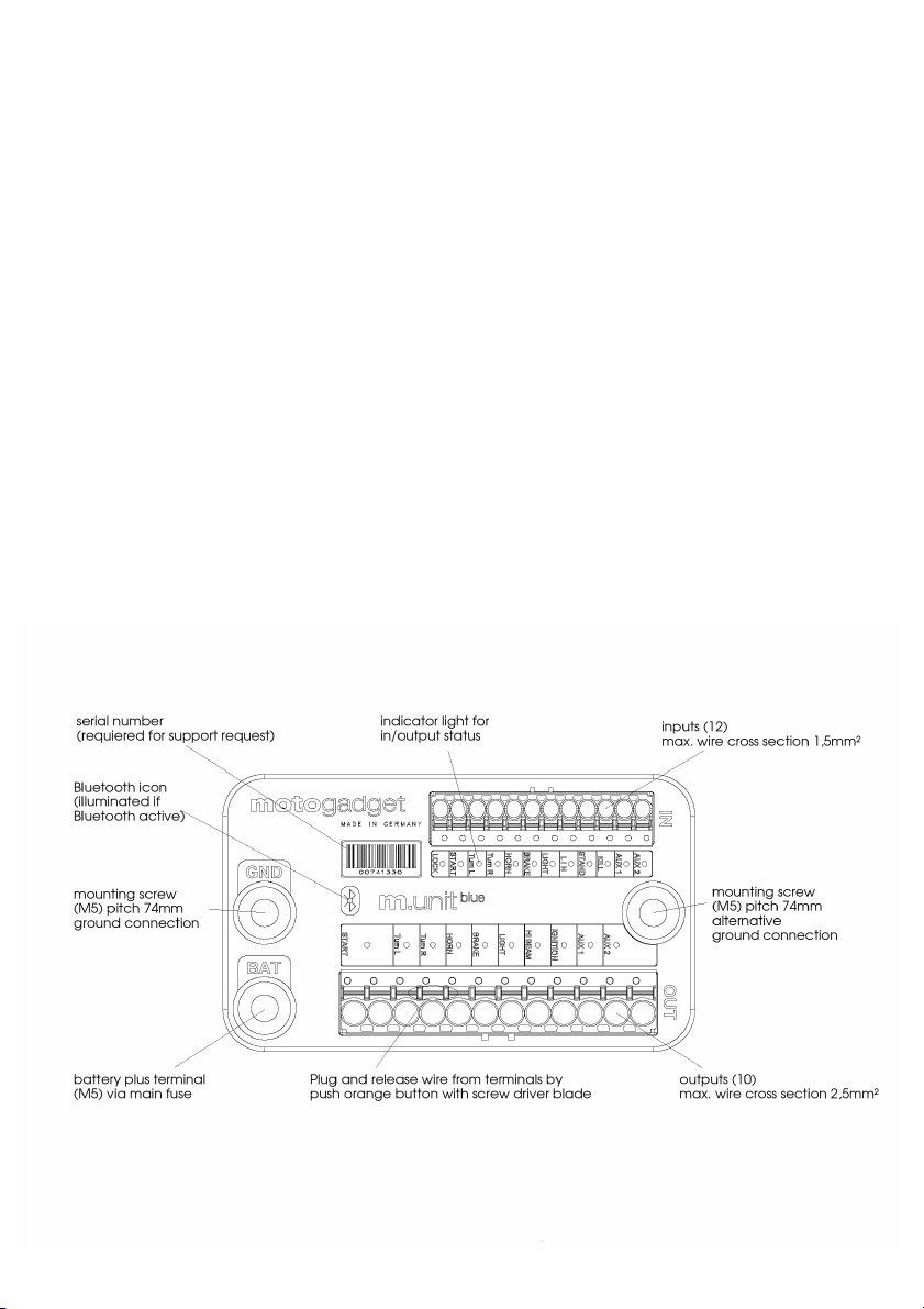
5 Technical Data And Functions
5.1 General Data
length / width / depth 90 / 53 / 30 mm
weight 110 g
threaded fastening bores 2 x M5, bore spacing 74 mm
standby current approx. 450 µA
operating voltage 6 – 18V , suitable for 12V electrical systems
operating temperature -20°... + 80°C
input circuits 12
output circuits 10 (START and AUX2 with 2 wire terminals each)
display 23 internal LED
5.2. Overview
3

6 Functions And Operation
The m-Unit is able to act as central control unit in the vehicle’s electrical system. It provides
following features:
Without smart phone:
• Complete digital push button control unit; optional 4 or 5 push button operation
• complete replacement of all OEM fuses 10 independent circuits are digitally supervised; a
circuit will be shut down in case of interferences after removing the interference, the safety
feature will be reset automatically
• integrated, digital, load-independent flasher relay; with programmable switch-off feature
(optional), selectable m-Wave mode
• turn signal setting for use as position light
• parking light, headlight flasher
• integrated digital brake-light modulator with programmable flashing sequence, acceleration-
controlled emergency brake-light
• pairing of m-unit with other motogadget products via LIN bus
• integrated starter relay for solenoid switch (up to 30A switching capacity)
• smart and fully configurable load control / shut-off for maximum starting power of battery on
starting process
• low beam and high beam control (up to 200W switching power) using just one push button
• integrated digital horn relay
• integrated position-independent alarm system
• integrated hazard light feature
• diagnostic feature for layout of input, output, circuit switching status, diagnosis of short-circuits
etc.
• two fully configurable auxiliary outputs AUX1 and AUX2
Pairing of m-unit with your smart phone via Bluetooth in combination with our „m.garage“
app providing advanced functionality:
• Pairing via Bluetooth LE (Low Energy); therefore extremely low power consumption of vehicle
and smart phone cell
• reporting of alarm events (date, time, vehicle „down“ etc.) to smart phone
• real-time analysis of all inputs / outputs, measurements of currents, voltage, temperature
• manual switching of outputs using m.ride app (except starter)
• firmware updates from any location
• configuration of setup menu using m.ride app
• Keyless Go feature using encrypted and secure pairing with your smart phone
• speedometer input is compatible with all standard vehicle speedometer inputs and
automatically calibrates via smart phone GPS
• the m.unit's speedometer input for storage and matching of vehicle's odometer enables for
vehicle management with an overview of maintenance tasks and states of wheels, chain,
brake pads, oils, operating supplies, spark plugs etc.
• logging of states, alarms and maintenance
• fully automatic driver's logbook
• display of parking position and „ping“ feature for locating your vehicle
• calibration and accurate current measurement enable detection of defective LED turn signals
and all standard illuminants
The m.unit is made of a newly designed high-performance thermosetting plastic and resistant to
moisture, heat, cold and vibrations. Microprocessor operated and supervised circuits guarantee
highest reliability. Current flow of each circuit is measured with high accuracy. In case of failure like
a short-circuit the concerning loop will be shut down in a split second. All switching activities are
carried out by state of the art semiconductor switches in a fast, wear-free and almost lossless way.
4

Therefore no other devices, relays, boxes or units as part of the wiring harness are necessary. A
complete new and minimised vehicle wiring can be made with minimal time, materials and effort;
compared to conventional solutions, only a fraction of space and cables is needed. State of the art
technology like pulse width modulation afford new possibilities like connecting rear and brake light
together with only one cable. When using m.button, the number of handlebar instruments
connections will be reduced to a single cable by use of our interference-free, proprietary data bus.
The current status of each circuit is shown by an internal LED at the m-unit's topside :
LED off - input not active, output not powered
LED on - input active, output powered – normal condition
short flashing - output shut-down due to short-circuit or overload
Turn Signals
Automatic shut-off can be adjust in setup menu. If this feature is activated a countdown will start
once the signal is flashing. If the adjusted countdown has ended the turn signal stop flashing. The
countdown will stop and set back if the brake is activated. Once the brake is released the
countdown start again with full time length. If a turn signal switch is used and signals has been
automatically shutting down, the switch has to set back to centre prior set the turn signal switch
again to left or right. If two turn signal push button are used is additionally the lane change mode
available. If the button is pressed very shortly the signals will flash only 3 times.
Hazard light
For starting the hazard light hold the push buttons for left and right turn signal for 2 seconds. If a
turn light switch is used, the hazard light function can only be activated if a additional hazard light
switch is activating both turn light inputs at the same time. The hazard light mode will stay active
even if the main (ignition) switch is deactivated.
Light control
In order to save the vehicles battery power the head light is switched off after key lock is switched
on. The head light will be activated automatically after pressing the start button. Further light
control modes can be selected under setup menu no. 8.
If a push button is used for high/low beam control, a short push will toggle between high and low
beam. Holding the button for 2s will switch off the light completely. Pressing the push button again
will switch the low beam light back on. A brief touch of push button is used for headlight flashing.
When using a switch for light control, it's possible to toggle between high and low beam only.
(Please refer to connection scheme.)
The light outputs (Light Hi Out / Light Low Out) can switch 120W each and are designed for a
maximum load of two halogen bulbs with 55W (low beam) and 60W (high beam) respectively.
The parking light has to be activated under setup menu no. 12. The parking light is switched on,
when on turning off the ignition the high beam light is activated. For the parking light feature, there
is no need for an extra illuminant; the feature is realised with the existing illuminant for low beam /
rear light. Parking light activation is signalised by two brief horn sounds. To avoid excessive battery
discharge, please make sure, the parking light is switched on for 2h max.
Kill switch
The running engine can be stopped in three different ways:
a) Double-clicking of engine start button
Pressing the button again after engine stop will crank and start the engine in normal way.
b) Connecting a separate kill switch or push button at the "config" terminal. If a push button is used
the engine is stopped if push button is shortly pressed. To release the kill function hold the button
again for 2 seconds or switch ignition lock off and on again. If a kill switch is used wait for 2
seconds between switching engine off and release the kill switch.
c) When implementing controls with four push-buttons, the engine is killed by pressing the buttons
for light and right turn indicator at the same simultaneously.
5
 Loading...