

MotoComm DSR-1003G User Manual
DSR-1003G
1
D
SR-10 0 3
G
HELMET CAMERA & DIGITAL RECORDER SYSTEM
Thank you for purchasing the MotoComm DSR-1003G. The
DSR-1003G is designed to provide motorcycle and powersport enthusiasts
with the most complete video and audio solution at an aordable price. With
proper care and use, your DSR-1003G will provide you with years of
enjoyment. Please read the entire instruction manual before using your
DSR-1003G. If at any time you have questions regarding this product please
contact Magnum International, the manufacturer of MotoComm products.
Enjoy your DSR-1003G and ride safe.
- The MotoComm Sta
MotoComm® is a Registered Trademark of RF Limited/Magnum International.
© 2008 RF Limited/Magnum International. All Rights Reserved.

DSR-1003G
2
WARNINGS AND CAUTIONS
· In some states it is illegal to have speakers inside a helmet. Please check with your state
and local laws before using this product.
· Do not attempt to operate any controls on the DSR-1003G or other accessories while in
motion on a motorcycle or vehicle. Never take your attention away from the safe
operation of the motorcycle or vehicle or the roadway.
· The installation and mounting of the DSR-1003G should not interfere with the safe and
normal operation of the motorcycle or vehicle. Improper installations that interfere with
the operation of the motorcycle or vehicle may lead to damage of property, injury and/or
loss of life.
· Make sure to install all cables so that they remain secure whether connected together or
not. Never install a cable that is loose or hangs down from the motorcycle or vehicle, or
has the potential to hang down if it becomes disconnected.
· Do not attempt to adjust or mount the DSR-1003G camera, headset, controls, or any
other part of the system while operating a motorcycle or vehicle. Attempting to adjust or
mount any part of the DSR-1003G while operating a motorcycle orvehicle may lead to
damage of property, injury and/or loss of life.
· Do not raise the speaker volume so that it interferes with the hearing of trac and other
external noises.
· Install and operate the DSR-1003G according to the instructions. Improper installations
and use may lead to damage of property, injury and/or loss of life.
· Do not put excessive force or strain on the cables or other components of the
DSR-1003G.
· By purchasing and/or using this product you are agreeing that MotoComm and RF
Limited / Magnum International and its subsidiaries are not liable or responsible for any
accidents, property damage, injuries, or fatalities, that may or may not be caused, directly
or indirectly, by use of any of its products. If you do not accept this agreement, please
return the purchased item, unused and in new condition, to the place of purchase.
LIMITED WARRANTY
RF Limited / Magnum International warrants that this product is free from defects in
materials and workmanship under normal use and conditions for a period of one (1) year
from the date of original purchase. This warranty is limited to the original purchaser of the
product and is not transferable. Any implied warranties are limited to one (1) year. This
warranty does not cover damage which results from modication, accident, misuse, abuse,
re, ood, lightning or other acts of nature or damage resulting from repairs or alterations
performed other than by RF Limited / Magnum International. This warranty gives you
specic legal rights, and you may also have other rights, which vary, from state to state.

DSR-1003G
3
Thank you for puchasing the DSR-1003G. The DSR-1003G is a complete, all inclusive camera and
digital recorder system designed for the motorcycle/powersport rider.
Please make sure to read the entire instruction manual to get the most out of your DSR-1003G.
CONTENTS
Component / Part Number List . . . . . . . . . . . . . . . . . . . . . . . . . . . . . . . . . . . . . . . . . . . . . . . . . . . . . . . . . . . . . . 4
Battery Charging / Connectors . . . . . . . . . . . . . . . . . . . . . . . . . . . . . . . . . . . . . . . . . . . . . . . . . . . . . . . . . . . . . . 5
Quick Setup Guide . . . . . . . . . . . . . . . . . . . . . . . . . . . . . . . . . . . . . . . . . . . . . . . . . . . . . . . . . . . . . . . . . . . . . . . . . . 6
DSR-7680-3G Initial Instructions / Controls . . . . . . . . . . . . . . . . . . . . . . . . . . . . . . . . . . . . . . . . . . . . . . . . . . . . 7
System Setup Menu. . . . . . . . . . . . . . . . . . . . . . . . . . . . . . . . . . . . . . . . . . . . . . . . . . . . . . . . . . . . . . . . . . . . . . . . . . 8
Recording a Video
Basic Setup / Connections . . . . . . . . . . . . . . . . . . . . . . . . . . . . . . . . . . . . . . . . . . . . . . . . . . . . . . . . . . . . . . 9
DSR-CM81 Camera Focusing . . . . . . . . . . . . . . . . . . . . . . . . . . . . . . . . . . . . . . . . . . . . . . . . . . . . . . . . . . 10
Camera Setup and Mounting . . . . . . . . . . . . . . . . . . . . . . . . . . . . . . . . . . . . . . . . . . . . . . . . . . . . . . . . . . 11
DSR-UM-1 Helmet Mounting . . . . . . . . . . . . . . . . . . . . . . . . . . . . . . . . . . . . . . . . . . . . . . . . . . . . . . 11 - 12
DSR-UM-1 Handlebar Mounting . . . . . . . . . . . . . . . . . . . . . . . . . . . . . . . . . . . . . . . . . . . . . . . . . . . . . . 13
DSR-BM-1 Pedestal Mount . . . . . . . . . . . . . . . . . . . . . . . . . . . . . . . . . . . . . . . . . . . . . . . . . . . . . . . . . . . . 14
DSR-SM4 Mounting Base . . . . . . . . . . . . . . . . . . . . . . . . . . . . . . . . . . . . . . . . . . . . . . . . . . . . . . . . . . . . . . 15
DSR-MIC-1 Remote Microphone Installation. . . . . . . . . . . . . . . . . . . . . . . . . . . . . . . . . . . . . . . . . . . . 15
DSR-BH-8AA Battery Holder Setup . . . . . . . . . . . . . . . . . . . . . . . . . . . . . . . . . . . . . . . . . . . . . . . . . . . . 16
DSR-12VDC-180CM Power Cable Installation . . . . . . . . . . . . . . . . . . . . . . . . . . . . . . . . . . . . . . . . . . 16
DVR Connection / Video Record Menu . . . . . . . . . . . . . . . . . . . . . . . . . . . . . . . . . . . . . . . . . . . . . . . . 17
My Videos Menu
Video Playback on LCD . . . . . . . . . . . . . . . . . . . . . . . . . . . . . . . . . . . . . . . . . . . . . . . . . . . . . . . . . . . . . . . . 18
Video Playback on TV. . . . . . . . . . . . . . . . . . . . . . . . . . . . . . . . . . . . . . . . . . . . . . . . . . . . . . . . . . . . . . 18 - 19
Deleting Videos . . . . . . . . . . . . . . . . . . . . . . . . . . . . . . . . . . . . . . . . . . . . . . . . . . . . . . . . . . . . . . . . . . . . . . 19
Video Playback on Computer
Transfering Video Files . . . . . . . . . . . . . . . . . . . . . . . . . . . . . . . . . . . . . . . . . . . . . . . . . . . . . . . . . . . . . . . . 20
Video Playback. . . . . . . . . . . . . . . . . . . . . . . . . . . . . . . . . . . . . . . . . . . . . . . . . . . . . . . . . . . . . . . . . . . . . . . . 21
Software Installation . . . . . . . . . . . . . . . . . . . . . . . . . . . . . . . . . . . . . . . . . . . . . . . . . . . . . . . . . . . . . . . . . . 21
SD Cards . . . . . . . . . . . . . . . . . . . . . . . . . . . . . . . . . . . . . . . . . . . . . . . . . . . . . . . . . . . . . . . . . . . . . . . . . . . . . . . . . . 21
Listening to MP3 Files . . . . . . . . . . . . . . . . . . . . . . . . . . . . . . . . . . . . . . . . . . . . . . . . . . . . . . . . . . . . . . . . . . 22 - 25
Tools . . . . . . . . . . . . . . . . . . . . . . . . . . . . . . . . . . . . . . . . . . . . . . . . . . . . . . . . . . . . . . . . . . . . . . . . . . . . . . . . . . . . . . 26
My Files. . . . . . . . . . . . . . . . . . . . . . . . . . . . . . . . . . . . . . . . . . . . . . . . . . . . . . . . . . . . . . . . . . . . . . . . . . . . . . . . . . . . 26
Games . . . . . . . . . . . . . . . . . . . . . . . . . . . . . . . . . . . . . . . . . . . . . . . . . . . . . . . . . . . . . . . . . . . . . . . . . . . . . . . . . . . . 27
Audio Record . . . . . . . . . . . . . . . . . . . . . . . . . . . . . . . . . . . . . . . . . . . . . . . . . . . . . . . . . . . . . . . . . . . . . . . . . . . . . . 27
My Photos . . . . . . . . . . . . . . . . . . . . . . . . . . . . . . . . . . . . . . . . . . . . . . . . . . . . . . . . . . . . . . . . . . . . . . . . . . . . . . . . 28
Company Information. . . . . . . . . . . . . . . . . . . . . . . . . . . . . . . . . . . . . . . . . . . . . . . . . . . . . . . . . . . . . . . . . . . . . . 28
DSR-1003G
4
The DSR-1003G includes many components. Please review the list below and make sure that
your system includes all items. If any component of the system is missing please contact
MotoComm at 1-877-624-6869 (toll-free) or by email at info@motocomm.com.
Qty. Part Number Description
1 DSR-CM81 Helmet/Bike Camera
1 DSR-7680-3G Digital Video Recorder/Playback Unit
1 DSR-MIC-1 Remote Microphone
1 DSR-BH-8AA Battery Holder
1 T-40 (MT-40) Stereo Helmet Speakers
1 TC-1 (MT-VX9) Music Adapter Cable for Helmet Speakers
1 DSR-BM-1 Pedestal Ball Camera Mount
1 DSR-UM-1 Universal Camera Mount
1 DSR-JUNC-1 4-Way Junction Cable
1 EXT-6 Coiled Extension Cable for Camera
1 EXT-6-180CM-S 6’ Straight Extension Cable for Camera
1 EXT-4 Coiled Extension Cable for Microphone
1 EXT-4-180CM-S 6’ Straight Extension Cable for Microphone
1 DSR-12VDC-180CM 6’ 12VDC Power Cord with Fuse
1 DSR-VAC-1 Video/Audio Cable
1 DSR-3.5S-1 3.5mm Stereo Patch Cable
1 DSR-USB-1 USB Cable
1 DSR-EPS-1 Earphone Speaker Headset
1 DSR-WS-1 Wrist Strap for DSR-7680-3G
1 DSR-AC-1 AC Adapter/Charger for DSR-7680-3G
1 DSR-VP-1 Carrying Case for DSR-7680-3G
1 ACC-1 Mounting Accessories for T-40 Speakers
3 DSR-SM4 Screw-Down Mounting Base for Camera
3 DSR-RT675 Medium Cable Tie for DSR-SM4
3 DSR-RT1100 Large Cable Tie for DSR-SM4
1 DSR-FOAM Adhesive-Backed Foam Cushion for DSR-UM-1
1 DSR-PB306 Plastic Carrying Case
All parts are available separately. Check with your dealer or contact MotoComm for details.
DSR-1003G
5
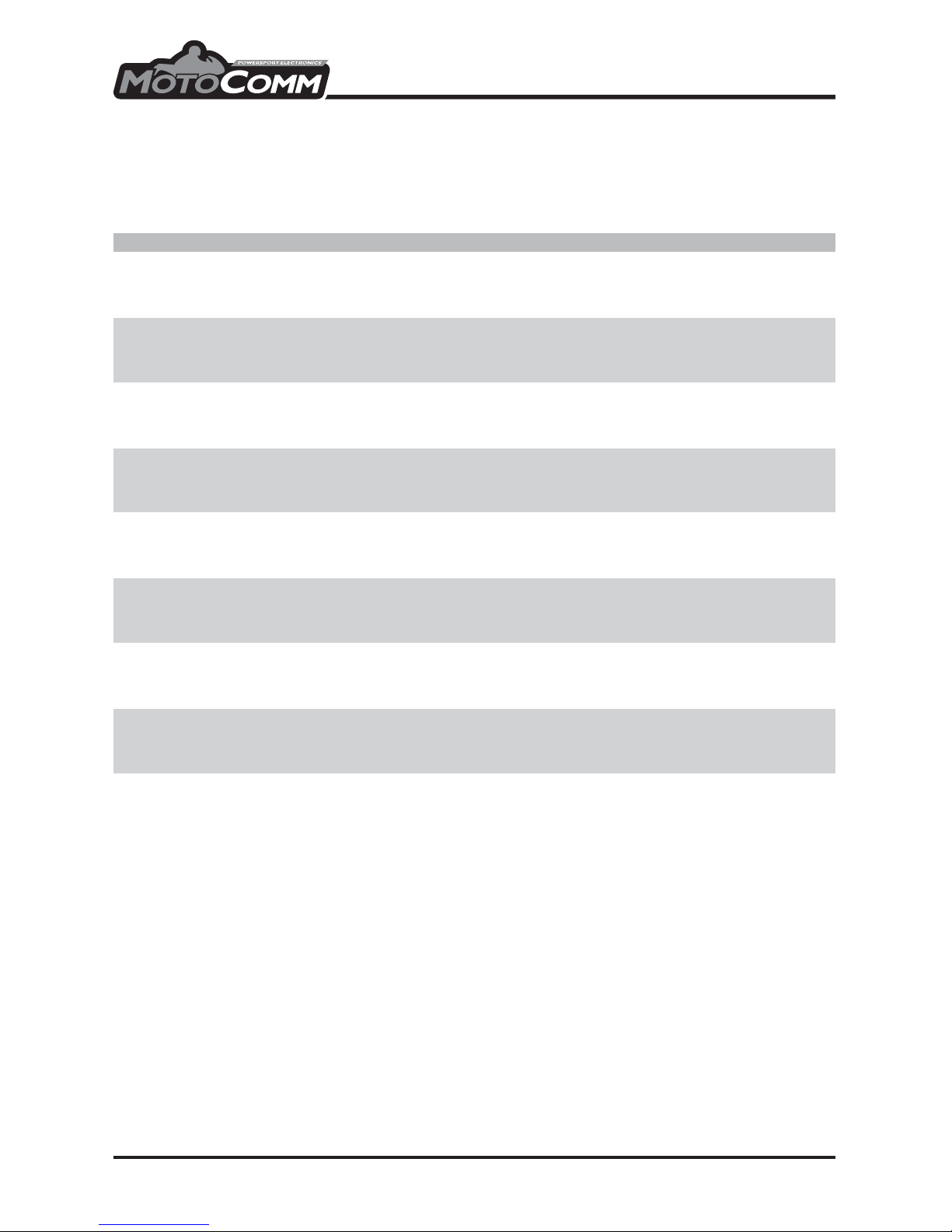
DSR-7680-3G Battery Charging
The DSR-7680-3G features an internal lithium-ion battery. With a full charge the battery will
operate the DSR-7680-3G for approximately 6 hours with the LCD screen on. For longer
operating durations, use the LCD Auto OFF battery conservation feature (see Setup Menu).
IMPORTANT: Fully charge the DSR-7680-3G internal battery prior to initial use.
To charge battery...
(1) Insert DSR-AC-1 into standard 110V AC wall outlet. Make sure that the LED light on the
DSR-AC-1 turns on when plugged into the wall outlet.
(2) Turn o DSR-7680-3G. NOTE: The
DSR-7680-3G may also be charged while
turned on, but the charging takes longer.
(3) Insert DSR-AC-1 plug into the DSR-7680-3G
charging port.
(4) The LED on the front of the DSR-7680-3G
will be solid red while the battery is charging.
(5) Charging is complete with the red LED turns o.
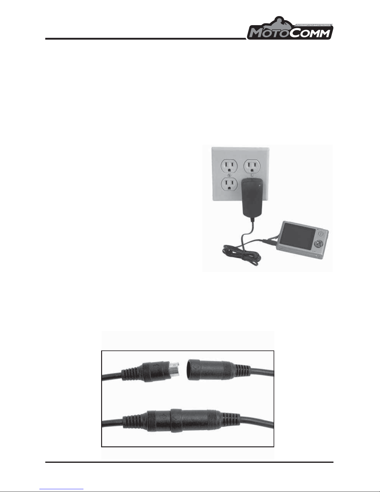
Connector Information
MotoComm’s mini DIN connectors feature a weatherproof molding. This weatherproof molding
is designed for a tight t. When mating these connectors for the rst time, it WILL BE DIFFICULT!
Take extra care in lining up the arrows on the connectors and slowly (but rmly!) push the
connectors together. It is a good idea to leave the plugs connected for several hours. This will
help ‘mold’ the connectors together and make for an ideal t. Subsequent connections will not be
as dicult.
DSR-1003G
6
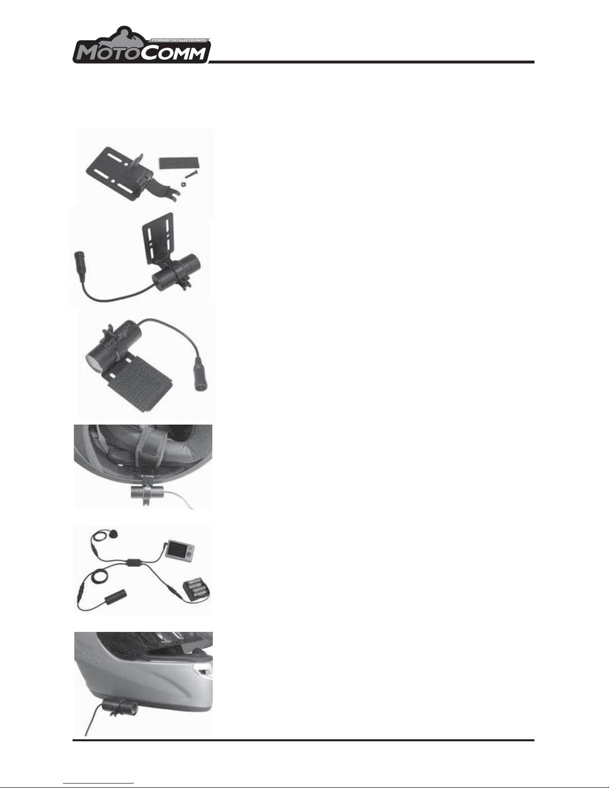
(1) Cut 2 small pieces of the DSR-FOAM material and stick them to the
inside surface of the DSR-UM-1 as shown.
(2) Place the DSR-CM81 in the DSR-UM-1 and tighten down the machine
screw and nut so that the camera is secure but can still be rotated in
mount.
(3) Cover the at part of the DSR-UM-1 with one side of the provided
hook-and-loop material, as shown.
(4) Stick the mating side of the provided hook-and-loop material to the
inside surface of the helmet shell. Attach the camera as shown.
(5) Connect the DSR-MIC-1 remote microphone to the DSR-JUNC-1
4-way junction cable (4pin connection).
(6) Leaving the DSR-CM81 camera on your helmet, connect it to the
DSR-JUNC-1 (6pin connection). If needed, use the EXT-6 coiled
extension cable for additional reach.
(7) Plug the DSR-JUNC-1 into the AV IN (top) jack on the DSR-7680-3G
DVR.
(8) Install 8 AA batteries into the DSR-BH-8AA battery holder and
connect it to the DSR-JUNC-1. NOTE: The 8 AA batteries power the
DSR-CM81 camera and DSR-MIC-1 remote microphone. Whenever
the battery pack is connected, the camera and microphone are ON
and are drawing power. The DSR-7680-3G DVR has its own separate
internal battery. The two power sources do not interact in any way.
(9) Turn on the DSR-7680-3G by pressing the power button for 5 seconds
and then releasing.
(10) The DSR-7680-3G defaults to the video record screen. If everything is
connected correctly and the batteries are good, you will see the
image from the camera on the DSR0-7680-3G display.
(11) Rotate the DSR-CM81 camera to set the horizon and then tighten
down the screw and nut on the DSR-UM-1 to secure the camera.
(12) If required adjust the vertical angle of the camera by reattaching the
hook-and-loop pieces at the correct angle. Keep in mind your normal
riding position - a hour long video of your tank is not that exciting!
(13) Press the enter (fII )button to start recording. Slide the Hold (control
lock) switch to the up, or locked, position. Put the microphone, DVR
unit, and battery pack in your jacket pocket, tank bag, waist pack,
camelback, etc. and go ride!
Quick Setup Guide
Although we highly reccomend that you read the entire manual, we also realize that you want to
get out and use your DSR-1003G immediately! Follow the steps below to start recording as
quickly as possible.
DSR-1003G
7
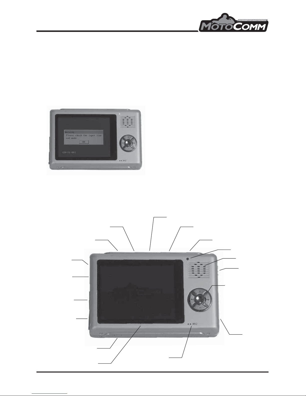
DSR-7680-3G Initial Instructions and Controls
Initial Instructions
(1) To turn on and o the DSR-7680-3G, press and hold the on/o button for 5 seconds and then
release it.
(2) When turned on, the DSR-7680-3G defaults to the Video Record screen - not the Main Menu
screen. The DSR-1003G is designed this way to make recording videos a quick and simple
one-button procedure - turn on the DSR-7680-3G with camera and cabling connected, and
push the enter (fII )button to start recording.
IMPORTANT: If you do NOT have the camera and
battery pack connected to the DSR-7680-3G
upon turn on, you will receive a warning
message asking you to check the AV input line
(camera connection) - see photo. See the Quick
Setup Guide or Recording a Video sections for
details on connecting the camera and cabling.
(3) To access the Main Menu from the Video Record screen (default screen after turn on) push
the escape (ESC) button.
Controls and Features
Power On/O
Mode
Play/Pause
M
Escape
AV Line In
(camera input)
AV Line Out
(headphones
out)
USB
Power/Charge
Reset
Navigation Buttons
+ : Up
- : Down
ee : Left
ff : Right
Internal Microphone
(for Audio Record feature ONLY)
LCD Screen
SD Card
LED Light
Speaker
Hold
Switch
DSR-1003G
8
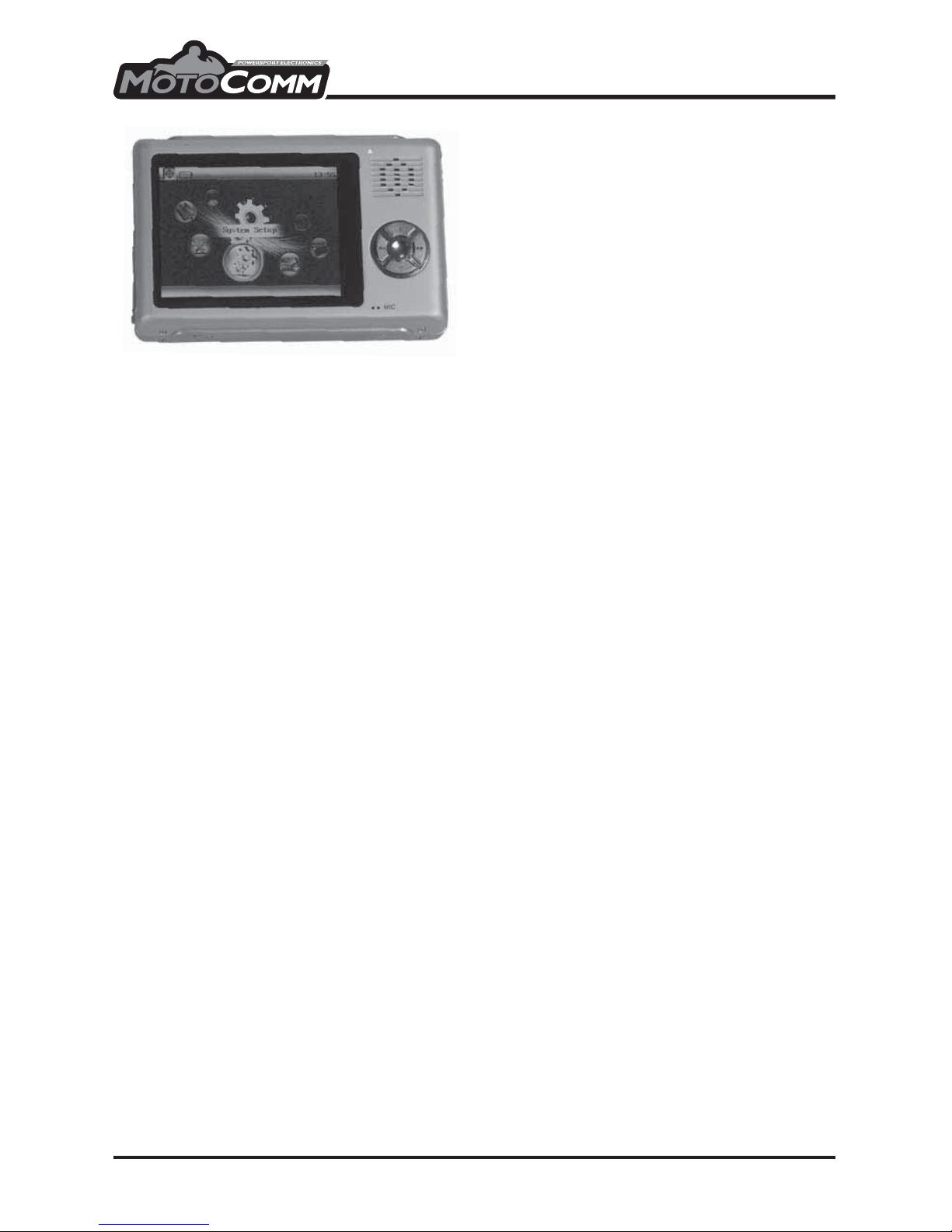
System Setup Menu
To access the System Setup menu, use the left
(ee ) and right (ff) navigation buttons on the
front panel to select the System Setup icon and
the press the enter (fII) button. To navigate in
the System Setup menu:
(1) Use the navigation buttons (ee , ff, +, - ) t o
highlight the selection.
(2) Use the enter (fII )button to select.
(3) Use the escape (ESC) button to exit.
Default
The Default feature reverts the DSR-7680-3G back to its factory default system settings.
Sound
The Sound feature allows you to turn the internal speaker and the key tone on and o.
(1) To turn the speaker and/or key tone on or o, highlight the desired selection and press the
enter (fII )button.
(2) “Success” will display on the LCD and return you to the System Setup menu.
Pwr AutoO
The Pwr AutoO feature will automatically turn o the DSR-7680-3G after a specied duration of
inactivity. IMPORTANT - It is recommended to have the Pwr AutoO feature set to Never.
(1) To activate the automatic power o feature, highlight the desired time setting (3 minutes, 15
minutes or 60 minutes) and press the enter (fII) button.
(2) “Success” will display on the LCD and return you to the System Setup menu.
Time
Sets the date and time for the DSR-7680-3G.
(1) Use the left (ee ) and right (ff) navigation buttons to select the year, month, day, hour and
minute.
(2) Use the plus ( + ) and minus ( - ) navigation buttons to change the date and time and press
the enter (fII )button.
(2) “Success” will display on the LCD and return you to the System Setup menu.
LCD AutoO
The LCD AutoO feature automatically turns o the LCD screen’s backlighting after a specied
duration of time. This feature helps conserve battery life - the LCD backlighting is one of the major
power drains of the system.
(1) To activate the LCD auto o feature, highlight the desired time setting (half min, one min,
three min) and press the enter (fII) button.
(2) “Success” will display on the LCD and return you to the System Setup menu.
(3) The LCD backlighting will now turn o automatically. Pressing any button on the
DSR-7680-3G will turn the backlighting on again.
(4) HINT: To avoid accidentally pushing a button and turning the backlighting on, use the Hold
switch on the side of the DSR-7680-3G. The hold switch locks the control buttons and makes
them inactive.
DSR-1003G
9
TIP: Use the above basic wiring information as the starting point for any installation. The camera and remote
microphone mounting locations will determine which, if any, of the extension cables will be used in your
install. When mapping out your install, keep in mind that you will want to protect the DSR-7680-3G unit from
the elements, while still being able to easily access it.
Recording a Video
Your DSR-1003G comes with everything you need (and more!) to record videos. There are many
possible mounting congurations with the DSR-1003G, but they all start with the same basic
setup. Use the information below as a starting point for your custom conguration and
installation.
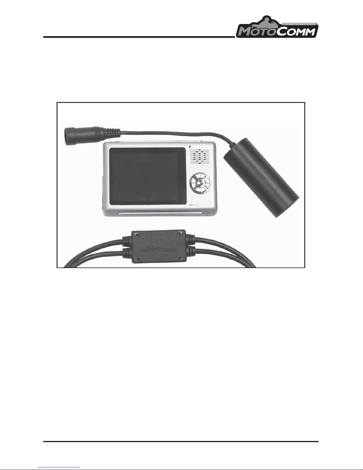
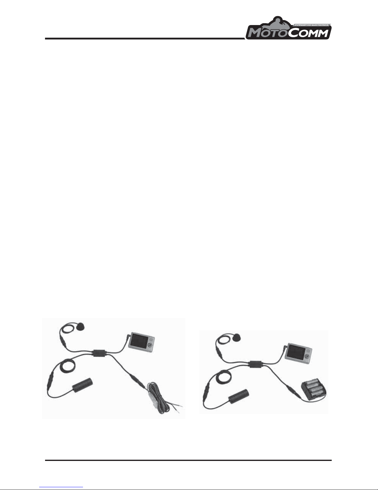
Basic Setup
There are over 20 items included with the DSR-1003G, but only 5 are required to record a video:
(1) DSR-7680-3G DVR unit
(2) DSR-JUNC-1 4-Way Junction Cable
(3) DSR-CM81 Camera
(4) DSR-MIC-1 Remote Microphone
(5) DSR-BH-8AA Battery Pack, or DSR-12VDC-180CM
Connections
(1) The DSR-JUNC-1 cable connects the 4 basic setup components of the DSR-1003G.
(2) The DSR-CM81 camera connects to the 6pin mini-DIN connector on the DSR-JUNC-1.
Depending on your installation, the camera connection can be extended using either the
EXT-6 coiled extension cable or the EXT-6-180CM six foot straight extension cable.
(3) The DSR-MIC-1 remote microphone connects to the 4pin mini-DIN connector on the
DSR-JUNC-1. Depending on your installation, the microphone connection can be extended
using either the EXT-4 coiled extension cable or the EXT-4-180CM six foot straight extension
cable.
(4) The DSR-JUNC-1’s 3.5mm, 4-contact plug connects to the DSR-7680-3G DVR AV Line IN jack.
(5) The DSR-BH-8AA or DSR-12VDC-180CM connects to the barrel-type DC power connector on
the DSR-JUNC-1.
Installation and Operation Note: The DSR-BH-8AA (12 volt battery pack) and the DSR-12VDC-180CM (12 volt
power cable) power the DSR-CM81 camera and DSR-MIC-1 remote microphone. **IMPORTANT** Whenever
the battery pack or power cable are connected, the camera and microphone are ON and are drawing power.
The DSR-7680-3G has its own separate internal battery. The two power sources do not interact in any way.
Basic Setup Connections
- OR -
 Loading...