

MOTIVE-RC R8SB Instruction Manual
MOTIVE-RC MOTIVE-RC
2.4GHz R8SB
D8_Mode Compatible Telemetry Receiver
INSTRUCTION MANUAL
Thank you for purchase of the R8SB receiver.
This manu al cont ains the complete direction on how to use this receiver, we encourage you to review the entire
manual before using these products.
R8SB receiver is designed for iRange X, Jumper, and FrSky Radio D8 Model system, please check the compatibility
before use!
Main Features
1. 1.2km far reaching range.
2. Satisfy with various model type with Physical channel PW M outputs, PPM, SBUS and RSSI outputs(For FC).
3. RSSI Output analog 0~3.3V.
4. Two analog telemetry ports (A1&A2) , A1 for internal receiver battery voltage sensor, A2 for external battery
voltage sensor(0~30V,1~6S).
5. One digital data-stream port (Rx,Tx).
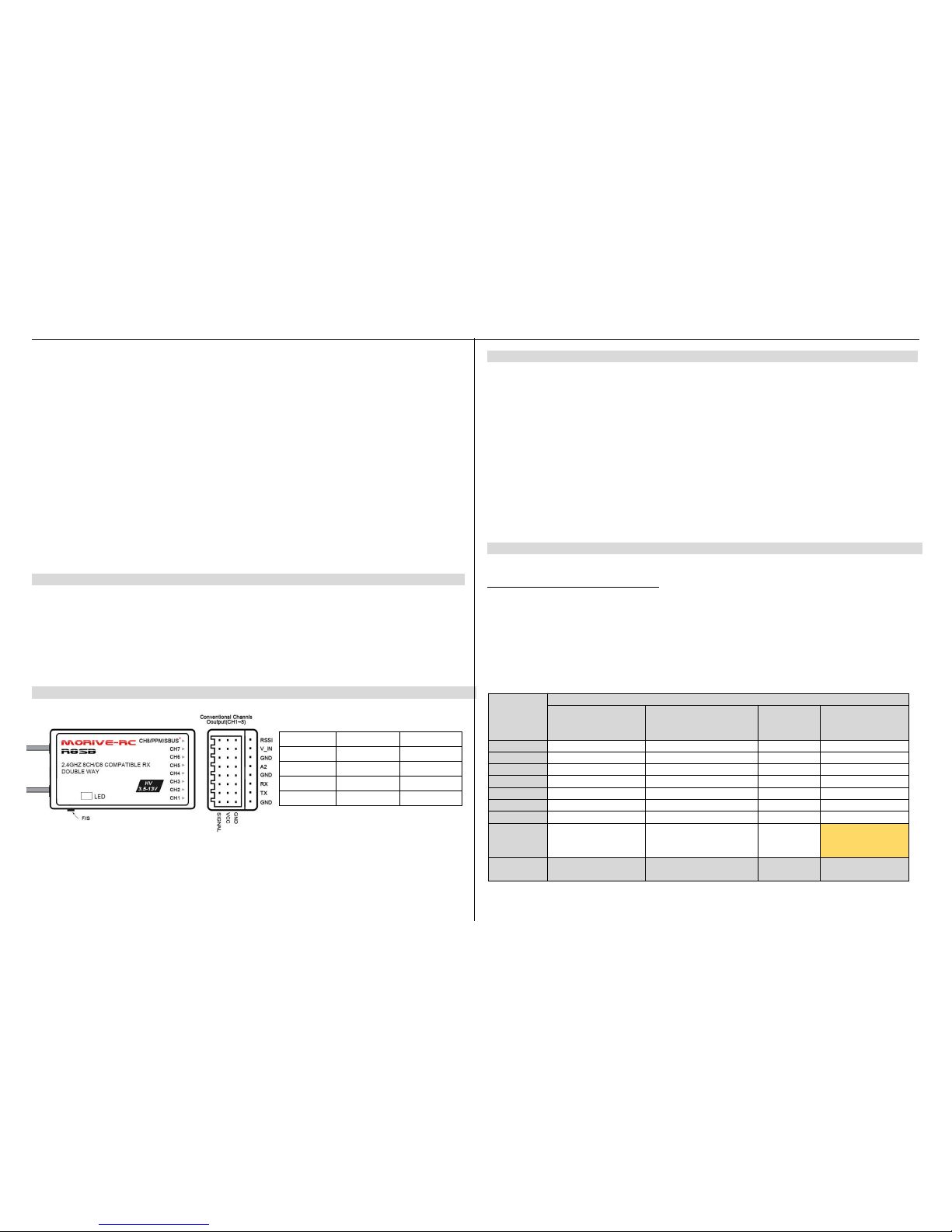
Layout and LED definition
*set different signal output by bind in different mode .
Specifications
Size: 35 x 21 x 12 mm (L x W x H)
Weight: 6.8g
Number of Channels: Up to 9CH from SBUS(CH1~8 for PWM, CH9 RSSI for FC)
Input Voltage Rang e: 3.5V - 13.0V (5V Normal Operating Range)
Range: above 1.2KM
Compatibility: iRange X , Jumper Transmitters, FrSky DJT/DFT/DHT, D8_Mode on all FrSky transmitters
Antenna installation:
R8SB receiver is made for high directivity consisting of two antenna, in order to maximize signal reception and
promote safe modelling has adopted a diversity anten na system. This allow the receiver to obtain RF signal on both
antennas and fly problem-free.
Be sure that the two antennas are placed at 90 degree to each other, and k eep away from conductive materials to
avoid short circuit.
Linking to Transmitter
Step 1:
Set R8SB receiver in Binding mode FIRST and Select operate mode you want (Please reference below sheet ):
Connect battery to R8SB receiver while holing the F/S button on the receiver enter binding mode.
Mode select:
1. Set receiver in binding mode;
2. Each press of the F/S button advances the r eceiver to the next Mode, when you reach the mode that you wish to
operate in, short press the button.
3.Once locked into the correct mode the LED will flashing in corresponding times constantly.
R8SB RECEIVER CHANNEL MODE SHEET
* Only PPM/SBUS Capable devices may be connect to the PPM/SBUS port. Analog servo or gyros should not be connect on
PPM/SBUS port.
RED LED
GREEN LED
INDICATING
ON
FLASHING
LINKING
OFFONNORMAL
FLASHING
OFF
NO SIGNAL
FLASHING
FLASHING
FAILSAFE
Receiver
output
Connector
Channels
Mode 1
CH 1~8
Normal Mode (20mS)
Mode 2
CH 1~8
High Speed Mode (3mS)
Mode 3
CH1~7 +
CH8 PPM
Mode 4
CH1~7 + CH8
SBUS/RSSI
11111
22222
33333
44444
55555
66666
77777
888
PPM
8Channels of Outp
ut w/ 9th Channel
Dedicated to RSSI
Red LED
Blink
1 time
2 times
3 times
4 times
MOTIVE-RC MOTIVE-RC
S
tep 2:
Set Tx module/ Transmitter in Binding M ode
1. Linking to Frsky Radio (X9D/X9D Plus/SE, QX7/QX7 S, X-Lite, X12S, X9E)
In the Taranis, go to MODE SETUP (page 2) in the model configuration. Go to Mode inside Internal RF and select
D8. We press BIND. The transmitter beeps, indicating it’s in bind mode. Wait for the green LED on the receiver
fast flashing and red LED solid on indica tes the receiver is receiving commands from the transmitter. The binding
procedure has finished. Receiver will auto enter Normal operation mode within 5 seconds. Exit the bind mode in
transmitter and turn off.
2. Linking the receiver to the XJT/DFT/DJT RF module
Using the dip switches of the XJT/DFT/DJT module, select the D8 mode . They should be in the following position:
switch 1 = ON, swi tch 2 = OFF. Press and hold the bind button and turn the transmitter on. Release the button. A
green light should blink in the module, indicating it’s in bind mode. Wait for the green LED on the receiver fast
flashing and red LED solid on indicates the receiver is receiving commands from th e transmitter. The binding
procedure has finished. Receiver will auto enter Normal operation mode within 5 seconds. Exit the bind mode in
transmitter and turn off.
3. Linking the receiver to iRange X
Take examp le by iRange X module m ounted on FrSky Taranis tr ansmitter (as long as your transmitter can use the
Open TX firmware, then it is compatible with module).
In the Taranis, go to MODE SETUP (page 2) in the model configur ation. Go to Mode External RF and select MULTI-
FrSky- D8. We press BIND. The transmitter beeps, indicating it’s in bind mode. Wait for th e g reen LED o n th e
receiver f ast flashing and red LED solid on indica tes the receiver is receiving commands from the transm itter.
The binding procedure has finished. Receiver will auto enter Normal operation mode within 5 seconds. Exit the bind
mode in transmitter and turn off.
4. Linking the receiver to Jumper Transmitter
In the Jumper transmitter, we go to the Model set up page, selecting FrSky and press BIND. Wait for the green
LED on the receiver fast flashing and red LED solid on indicates the receiver is receiving commands from the
transmitter. The binding proced ure has finished.Receiver will auto enter Normal operation mode within 5 seconds.
Fail-safe
Fail-safe is a useful f eature in which all controls move to a preset position whenever the control signal is l ost for a
period of time. R8SB receiver suppo rts fail-safe function for all chan nels. Follow the steps below to set fail-safe
positions for each channel:
1.Bind the receiver first and turn on both the transmitter and receiver;
2.Move the controls to the desired fail-safe position for all channels;
3.Press briefly the F/S button of the receiver (less than 3 second). The GREEN & RED LED of the receiver will flash,
indicating the fails-afe position has been set in the receiver.
Re-bind the receiver to disable the fail-safe function.
Senior Functions
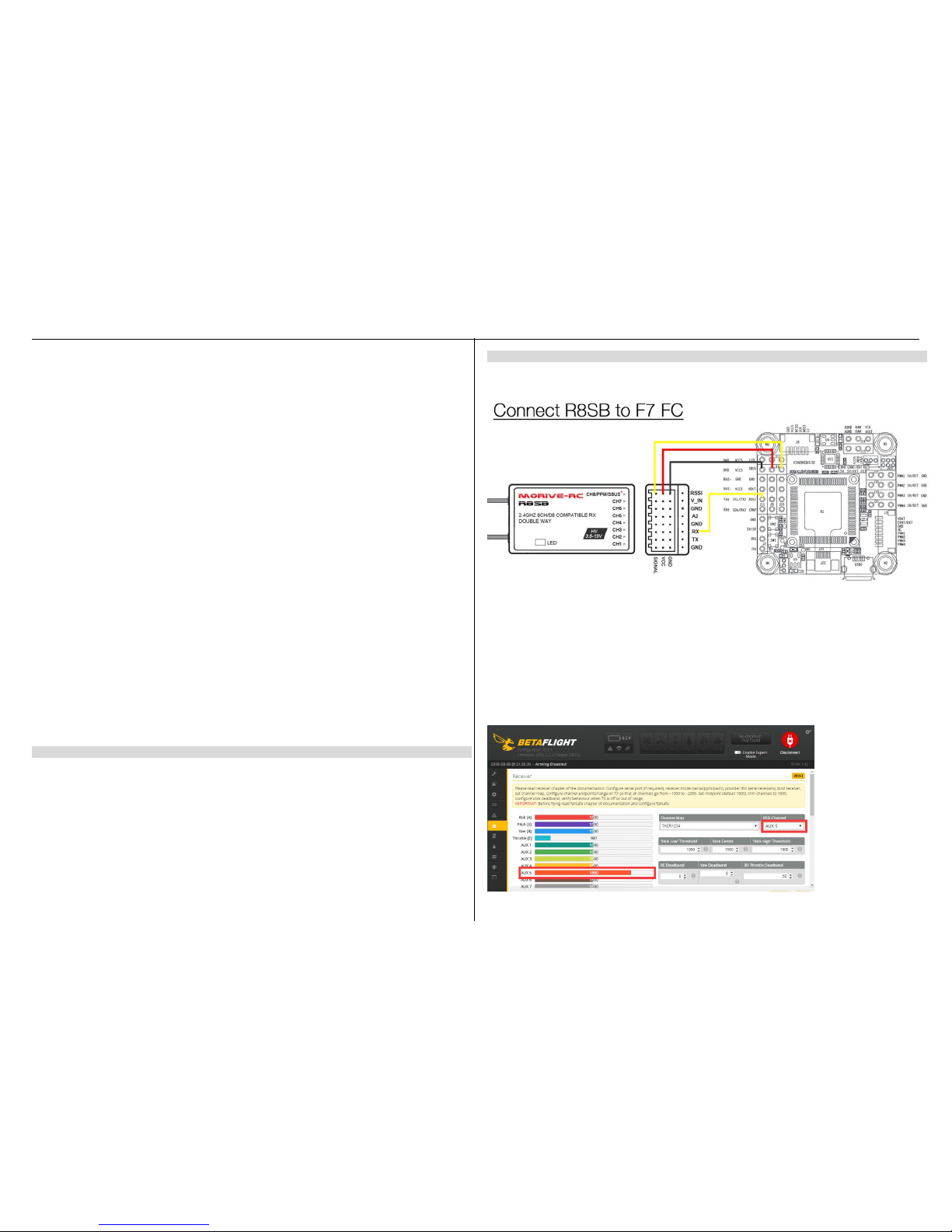
1. Receiver Configuration(SBUS & RSSI ) in the Beat flight configuration:
Binding receiver in SBUS mode, connect CH8 channel of receiver to UART RX port of FC
In the GUI PORTS tab, select the UART that corresponds to the receiver (usually UART2 in F7 flight controllers) and
activate Serial RX.
Save by clicking on the Save and Reboot butt on.
In the CONFIGURATION tab, in the Receiver Mode section, select RX_SER IAL.
In the same tab, in th e Serial Receiver Provider section, select SBUS.
Save by clicking on the Save and Reboot butt on.
Go to the RECEIVER tab and confirm that all ch annels are responding correctly.
AUX 5 should be indicati ng a higher value than the other channels, this is the RSSI channel. In the ‘RSSI Channel’
drop down, choose AUX 5. Now, the RSSI value can be set to display in the Betaflight OSD.
Enter the OSD tab and activate the ‘ RSSI Value’ button under ‘Elements’. Positio n the RSSI indicator anywhere on
the OSD display and press save. Now you can view the real-time R SSI strength in your goggles.
 Loading...