

Motison CyberStat CY1201 User Manual
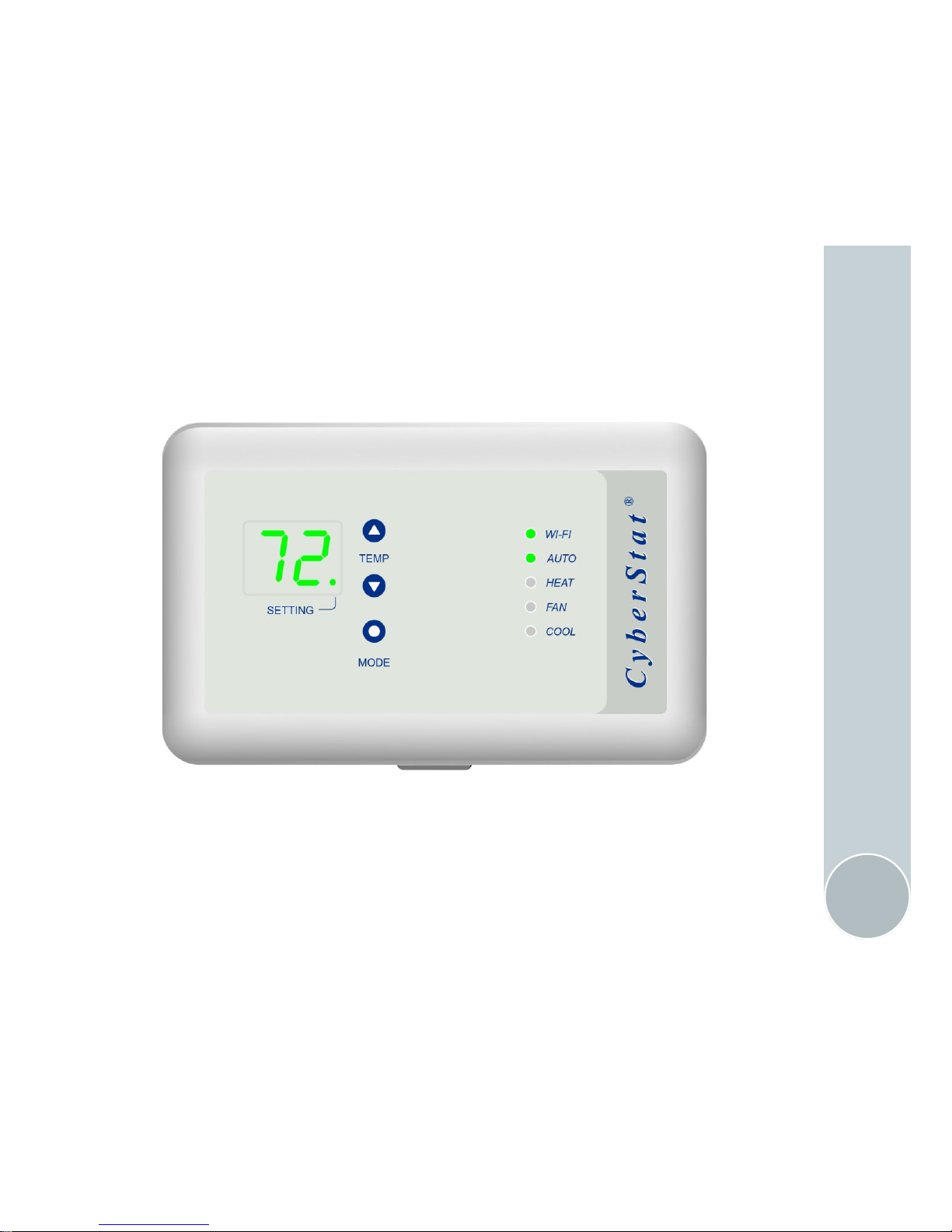
Motison
CyberStat
®
CY1201
Due to continuous improvement, some features and appearance may have changed
User’s Manual

2-year limited warranty: Motison warrants this product to be free
from defects in the workmanship, construction and materials, under normal use and service, for a period of two year from the date of purchase
by the consumer. If at any time during the warranty period the product
is determined to be defective, Motison will replace or repair it.
This warranty does not cover removal or re-installation costs. This war-
ranty shall not apply if it is shown by Motison that the defect or malfunction was caused by damage which occurred while the product was in
the possession of a consumer.
Motison's sole responsibility shall be to repair or replace the product
within the terms stated above. Motison shall not be liable for any loss or
damage of any kind, including any incidental or consequential damages
resulting, directly or indirectly, from any breach of any warranty, express or implied, or any failure of this product. Some states do not allow
the exclusion or limitation of incidental or consequential damages, so
this limitation may not apply to you.
If the product is defective, please contact Motison immediately. To
make a claim, email to support@motison.com or call 1-855-222-6572.
Warranty
2

Internet connected through 2.4 GHz Wi-Fi (WEP/WPA/WPA2)
Monitor and control from anywhere anytime
Three independent 7 day programs + manual mode
Auto recover after power outage
Temporary and permanent hold
Auto switchover between heating and cooling modes
Customize programs from a desktop or tablet computer
No batteries required (but requires a common or ‘C’ wire)
1
Works with Heat Pump and Conventional systems
2,3
Heat pump with auxiliary heat: 1 cooling and 2 heating stages
Conventional system: 1 cooling and 1 heating stages
Maximum control current: 400 mA (any terminal)
Temperature accuracy ±1°F
1. If you do not have a ‘C’ wire, you can: 1. use fan wire as ‘C’ wire
(you will not be able to use fan independently) or 2. use an external
power supply.
2. CyberStat does not work with line-voltage baseboard heaters.
3. CyberStat will not work if you have separate Rc and Rh wires. This
limitation does not apply if there is a jumper between Rc and Rh
terminals.
Features & Compatibility
3
Remove Old Thermostat
4
1. Turn off the old thermostat.
2. Turn off power to the heating and cooling system.
3. Remove any locking screw and then remove the face plate.
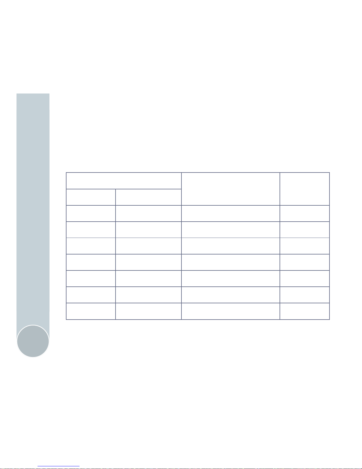
4. Record the terminal names and corresponding wire colors below.
(Depending on your system, you may not have all the wires listed here)
5. Now remove the wires and the old wall plate.
Old Thermostat Terminal
Wire Color
(please fill in)
CyberStat
Terminal
Terminal Purpose
C Common or Ground C
R, Rc or Rh 24 V AC Hot R
O or B Reversing Valve O/B
Y Compressor Y
W Heat or Aux Heat W
G Fan G
Install CyberStat
5
1. Detach the back cover of CyberStat and place it on the wall. Mark
the mounting hole locations with a pencil. You may want to use a level
at this time.
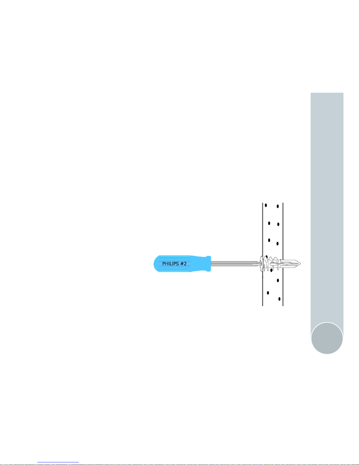
2. Use a #2 Philips head screwdriver to screw-in the provided drywall
anchors at marked locations. If the old thermostat did not use drywall
anchors then most likely there is a wood bracing behind the drywall. In
that case you should skip this step.
Tip: The drywall anchor does not require pre-
drilling. However, making a dimple with the tip of
a screw driver at the marked location will make
the placement more accurate.
3. Mount the back cover on the wall.
4. Connect the wires to the terminals matching the terminal names. See
wiring diagrams for your system on pages 6-13.
Conventional Heat/Cool
6
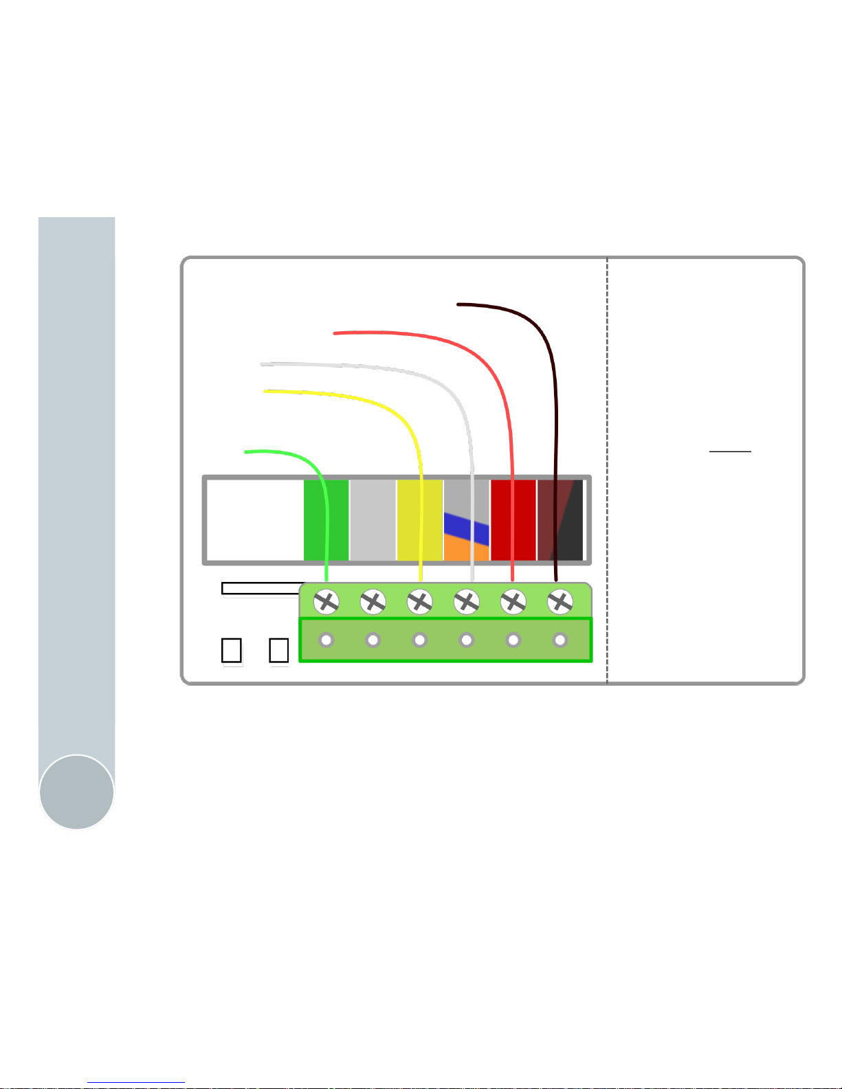
Wiring option 1 for Conventional Heat and/or Cool system
Use this wiring option if you have a C wire
Yellow and green wires are not required for a heat-only system
White wire is not required for a cool-only system
Notes on C wire:
Make sure that C wire is
connected to C terminal
on the furnace.
You will not get stable
power if C wire is con-
nected to any other
terminal on the furnace.
A previously unused wire
can be used as C wire.
Simply connect it to C
terminal on furnace and C
terminal on thermostat.
24 V AC neutral (C wire)
24 V AC hot
Heat
Cool
Fan
C
R
O/B/W1
Y
G
W2
Conventional Heat/Cool
7
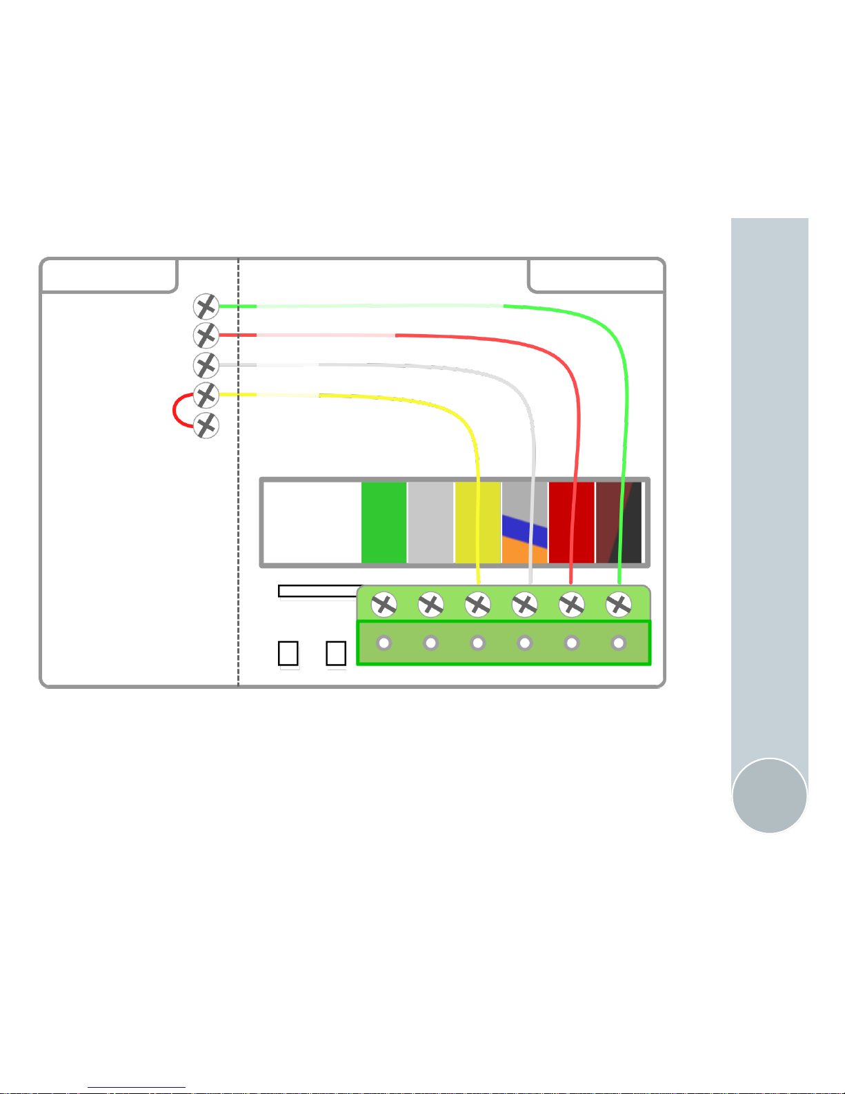
Wiring option 2 for Conventional Heat and/or Cool system
Use this wiring option to re-purpose green wire as C wire
Re-purposing requires some wiring changes on the furnace side
With this option, you will not be able to use fan independently
Furnace side wiring
to re-purpose green
wire as C wire
1. Move green wire
to C terminal and
2. Put a jumper
across Y and G
terminals
24 V AC neutral (C wire)
24 V AC hot
Heat
Cool
C
R
W
Y
G
Furnace CyberStat
C
R
O/B/W1
Y
G
W2
Conventional Heat/Cool
8
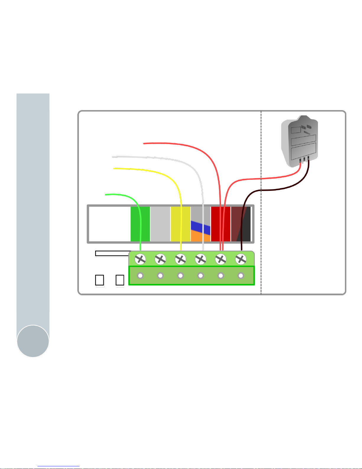
Wiring option 3 for Conventional Heat and/or Cool system
Use external power supply if you do not have a C wire
Yellow and green wires are not required for a heat-only system
White wire is not required for a cool-only system
24 V AC adapter is
required if you do
not have a C wire.
If using an external
power supply, you
will have two wires
going to R terminal.
24 V AC hot
Heat
Cool
Fan
C
R
O/B/W1
Y
G
W2
 Loading...