

Page 1
Motion Pro Suspension Bearing Tool P/N 08-0294
The Motion Pro Suspension Bearing Tool is designed to remove and install the bearings in the swing arm and
linkage pivots. The examples and tool tips shown below will help you in servicing your machine.
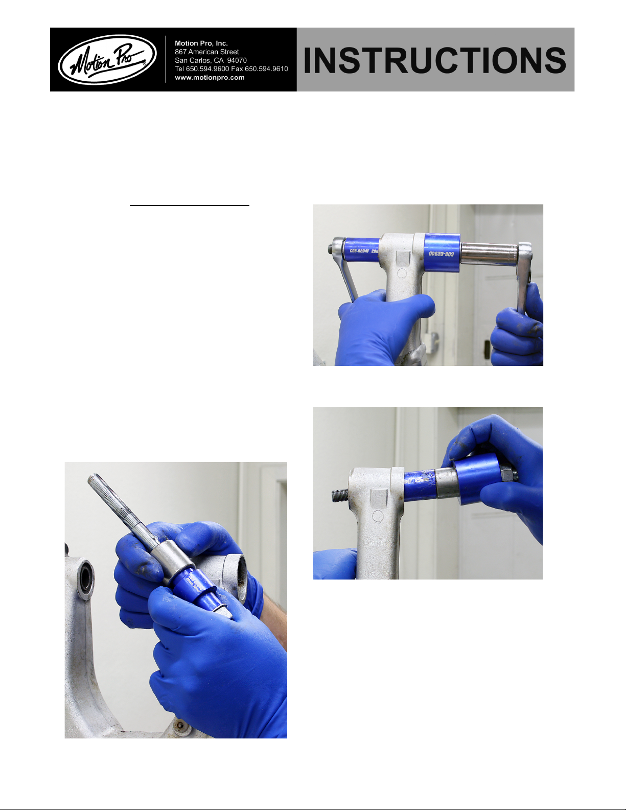
Section 1. Swing Arm Bearings
Fig 1
Fig 2
d. Clean all bearing surfaces and inspect for
damage.
e. Pack new bearings with a liberal amount of high
quality bearing grease. Apply a thin layer of grease
on the inside of the swingarm bearing surface.
This will help to prevent the new bearing from
galling during installation.
f. Install bearing onto the corresponding bearing
driver as shown in fig 3. The bearing driver will
hold the loose needles in place during installation.
a. Remove swingarm, seals, retaining
rings, and spacers. Make absolutely sure
that there are no internal circlips that may
be hidden under the grease.
b. Select the correct size driver for your
bearing and assemble the puller as shown
in Fig1.
c. Make sure as you start to tighten
the assembly that the bearing cup
(C08-0294D) is centered on the swingarm.
Pull the bearing through the swingarm
and into the bearing cup as shown in
Fig 2.
Fig 3
I08-0294A 5/2009
Page 2
Section 2. Rocker Pivot
Every manufacturer has a slightly different suspension linkage system. The examples here are performed
on a 2006 CRF450R. Refer to your shop manual for any specific instructions or procedures that are not
covered here.
g. Assemble the bearing driver as shown in Fig 4.
Tighten screw until the driver bottoms out on the
inside bearing surface.
a. Remove all seals and inner spacers from
the rocker
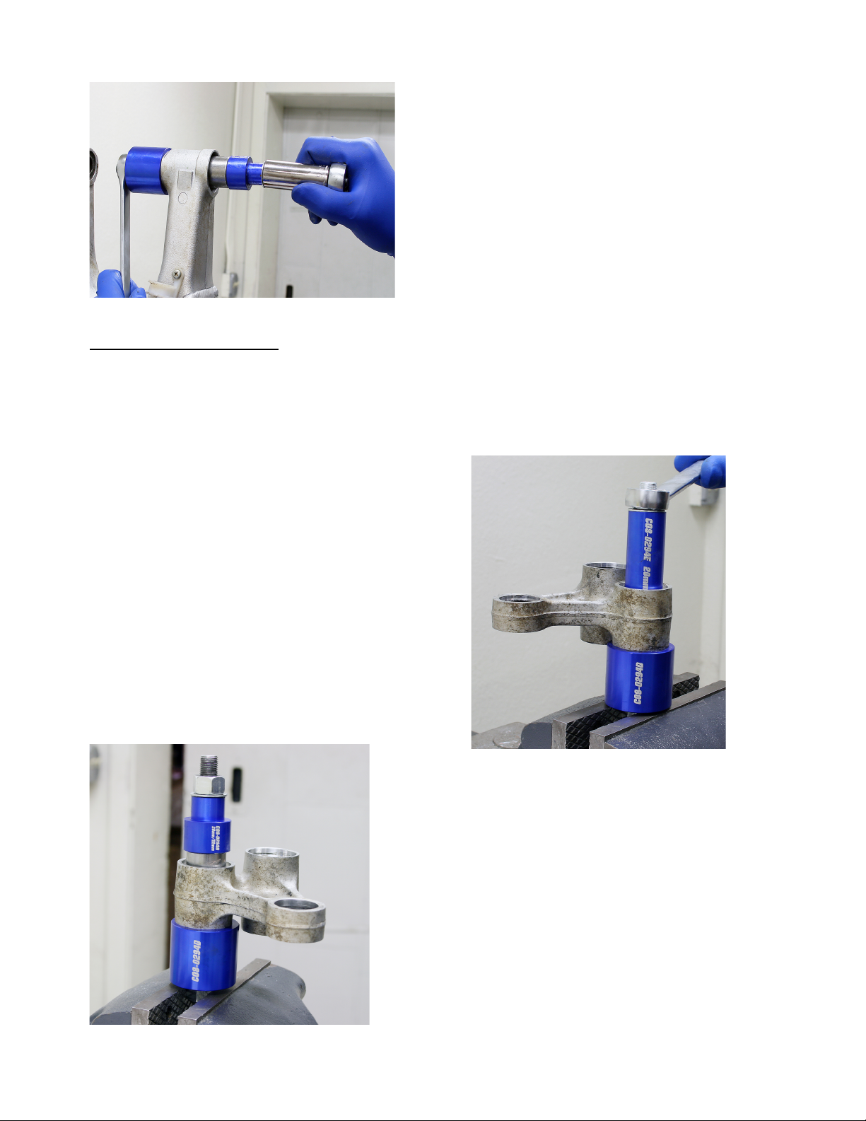
b. Using the appropriate bearing remover,
assemble the tool as shown in Fig 5. If you do
not have a bench vise you can use a wrench
on both nuts.
c. Tighten the nut until the bearing is pushed
completely out of the rocker and into the
bearing cup.
d. Clean all bearing surfaces and inspect for
damage.
e. Install bearing onto the corresponding bearing
driver as shown in Fig 6. The bearing driver will hold
the loose needles in place during installation.
f. Assemble the bearing driver as shown in Fig 4.
Tighten screw until the driver bottoms out on the
inside bearing surface.
g. Reinstall all seals and bearing spacers. Be sure to
pack the new bearings with a high quality grease
before reinstalling the components onto the
motorcycle.
Fig 4
Fig 5
Fig 6
I08-0294A 5/2009
Page 3

Section 3. Connecting Link
Again, most manufacturers have a slightly
different suspension linkage system.
The examples here are performed on a 2006
CRF450R. Refer to your shop manual for
any specific instructions or procedures that
are not covered here.
a. Remove all seals and inner spacers.
b. Fully tighten the blind bearing remover on
the inner lip of the needle bearing then
assemble the tool as shown in Fig 7. Be sure
that the lip of the blind bearing remover is fully
engaged on the bearing.
c. Apply a small amount of grease onto the
threads of the puller and washer
d. Remove bearing as shown in Fig 8.
e. Clean all bearing surfaces and inspect for
damage.
f. Assemble the bearing driver as shown in Fig
9 and Fig 10. Tighten screw until the driver
bottoms out on the inside bearing surface
g. Install new greased bearing onto the bearing
driver and assemble the tool as shown in fig 9
and 10
h. Replace all seal, inner spacers, and clips.
Fig 7
Fig 8
Fig 9
Fig 10
I08-0294A 5/2009
 Loading...