

Motion Fitness eyeplay Manual Book
GUIDEBOOK
for
Technical Partners
Version 1.04

Table of Contents
Table of Contents ...........................................................................................................................3
Introduction ...................................................................................................................................4
General .................................................................................................................................................................. 4
Operations Workflow ............................................................................................................................................ 5
EyePlay device description ..............................................................................................................6
Device overview and dimensions .......................................................................................................................... 6
Device components ............................................................................................................................................... 7
EyePlay device installation ..............................................................................................................9
Working conditions ................................................................................................................................................ 9
Choosing installation spot ..................................................................................................................................... 9
Preparing the device for installation ................................................................................................................... 10
Installing EyePlay Device...................................................................................................................................... 11
Powering up, adjusting and calibrating ............................................................................................................... 14
Basic Operation Instructions ......................................................................................................... 16
Reviewing the License Tab ................................................................................................................................... 17
Setting the Display Tab ........................................................................................................................................ 17
Projector configuration........................................................................................................................................ 19
Configuring Games in the Applications Tab (floor/wall units) ............................................................................. 20
Using the Events Mode (floor/wall units) ............................................................................................................ 21
Keyboard Controls ............................................................................................................................................... 22
Table Menu (table units only) .............................................................................................................................. 22
Quick Reference guide ......................................................................................................................................... 22
Technician access ......................................................................................................................... 23
Eyeclick Toolbar ................................................................................................................................................... 23
Shutting Down ..................................................................................................................................................... 24
Technical support and stock management ..................................................................................... 25
Technical Support Workflow ............................................................................................................................... 25
Support Contact details ....................................................................................................................................... 26
EyeClick Knowledge base ..................................................................................................................................... 26
On-site support visits ........................................................................................................................................... 26
Lamp replacement ............................................................................................................................................... 27
Projector replacement ......................................................................................................................................... 28
Computer replacement ....................................................................................................................................... 29
Remote controller and keyboard ......................................................................................................................... 29
Handling faulty equipment - RMA ....................................................................................................................... 30
Shared database .................................................................................................................................................. 31
Troubleshooting................................................................................................................................................... 32
Billing and Invoicing ...................................................................................................................... 33
Annexes ....................................................................................................................................... 34
Annex A: Pre-installation requisites (to be filled by client) ................................................................................. 35
Annex B: Site Survey Form (To be filled by Installer, or client in special cases) .................................................. 36
Annex C: Installation Report (To be filled by Installer) ........................................................................................ 38
Annex D: Client Acceptance Form (To be filled by client).................................................................................... 39
Annex E: Technical on-site service report (To be filled by technician) ................................................................ 40
Guidebook for Technical Partners - All rights reserved, EyeClick Ltd
3
Ver 1.04 – August 6, 2015
Contents
Introduction
The purpose of this guidebook is providing all required information to EyeClick’s Technical partners in order to install,
maintain, and support EyePlay devices. It includes all relevant information and workflows.
Online access available at: www.eyeclick.com/Guidebook/
General
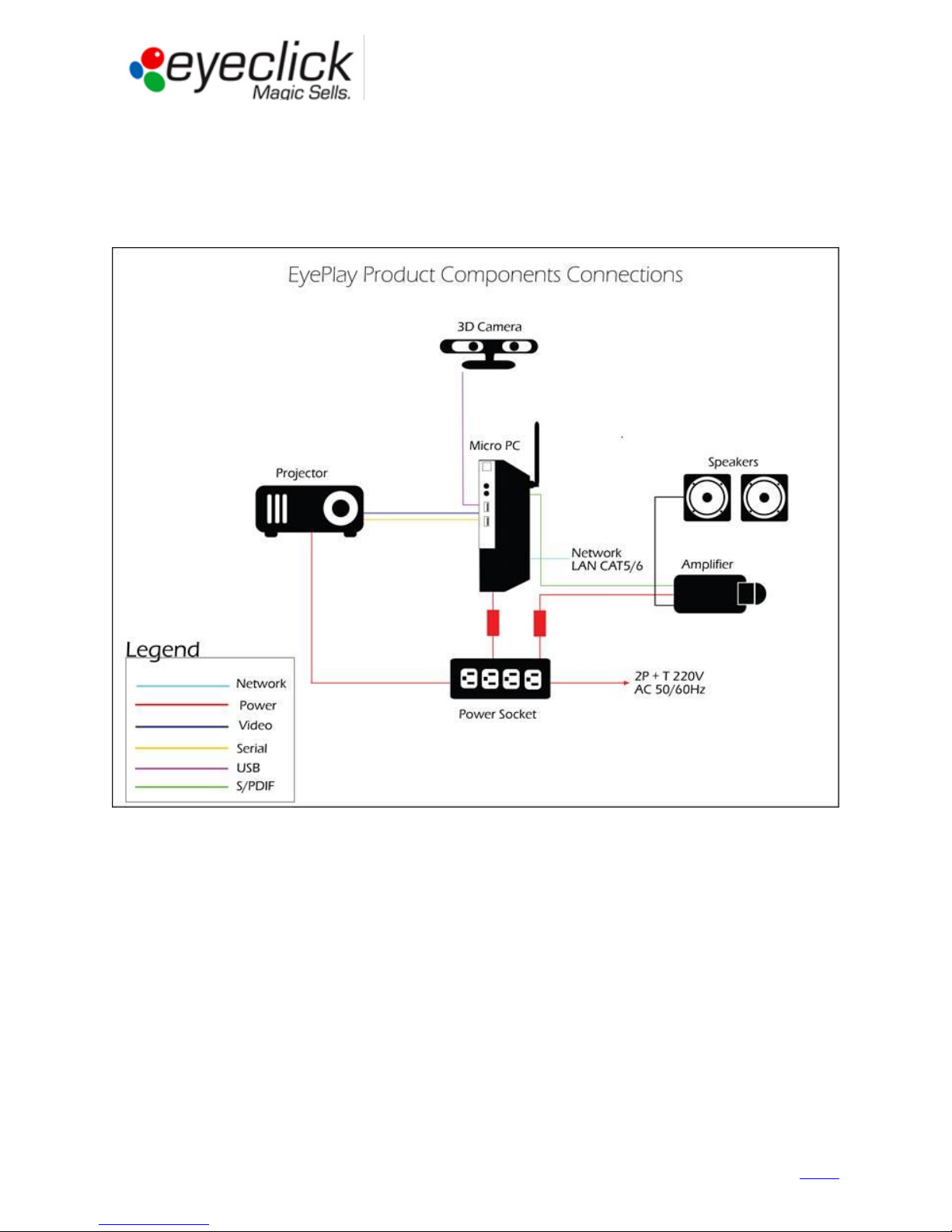
EyePlay interactive systems use a horizontally positioned projector and an angled mirror to project an
image on floor, wall or table. Most hardware components in each device are similar, software is
different between units.
Image size and brightness are affected by the facility lightening and ceiling height.
Guidebook for Technical Partners - All rights reserved, EyeClick Ltd
4
Ver 1.04 – August 6, 2015
Contents
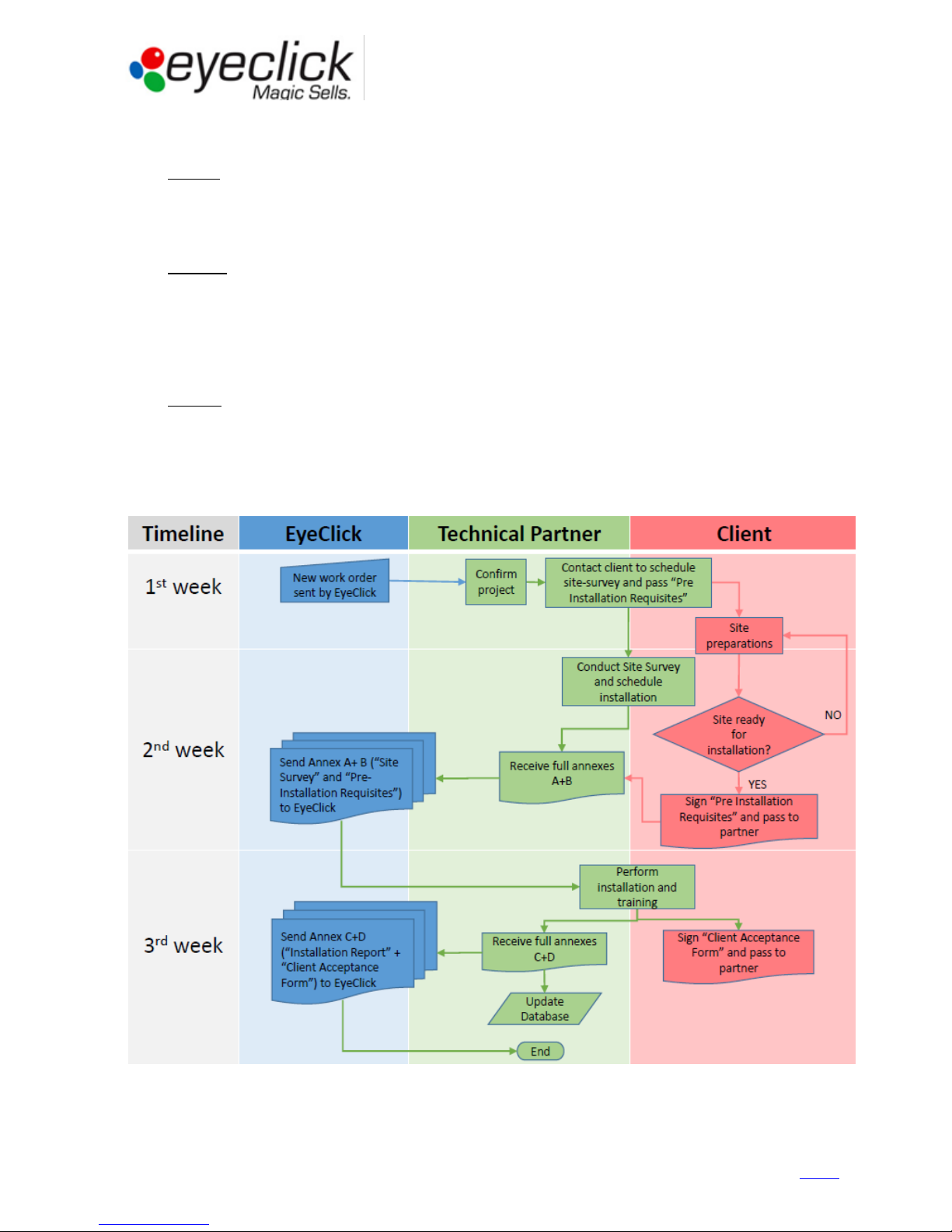
Operations Workflow
st
1. 1
week
EyeClick will notify the partner with a new EyePlay installation project. Partner will acknowledge.
Partner will contact the client and pass “Pre-installation requisites” [See ANNEX A].
He will schedule a Site Survey to take place once site preparations are nearly complete.
nd
2. 2
week
Partner will conduct a site survey on site using a “Site survey form” [ANNEX B]” and will schedule installation date.
Partner will make sure client finalizes preparations and will make sure client returns a signed copy of “Preinstallation requisites
Partner will send both forms (A+B) to EyeClick Operations and update shared projects list.
EyeClick will approve installation after receiving both documents.
rd
3. 3
week
Partner will perform installation and fill in “Installation Report” [ANNEX C]. Client will sign “Acceptance form”
[ANNEX D]. Partner will send both forms to EyeClick Operations
Partner will update shared database.
Operations Workflow Scheme
Guidebook for Technical Partners - All rights reserved, EyeClick Ltd
5
Ver 1.04 – August 6, 2015
Contents
External fence (removable):
601mm x 601mm
Bottom plate: 594mm x 594mm
Base: 592mm x 592mm
Mounting bridge height: 287.6mm
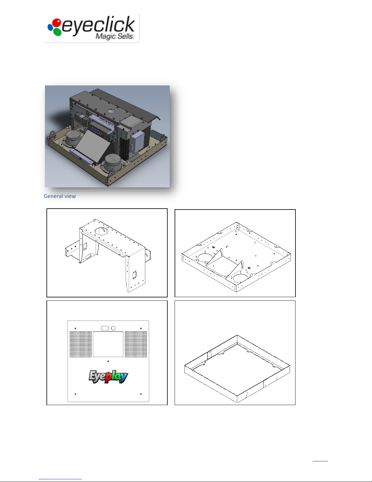
Device dimensions
EyePlay device description
Device overview and dimensions
General view
Guidebook for Technical Partners - All rights reserved, EyeClick Ltd
6
Ver 1.04 – August 6, 2015
Contents
Device components
The system integrates the following components: Computer, Projector, Motion detection camera, Sound speakers
and Audio amplifier. Additional items (packed in keyboard box) are: Wireless keyboard + USB dongle, Wireless
antenna and Projector remote controller.
Guidebook for Technical Partners - All rights reserved, EyeClick Ltd
7
Ver 1.04 – August 6, 2015
Contents
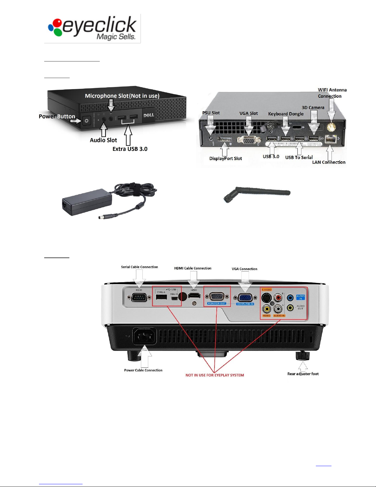
Power supply unit (PSU)
WIFI antenna
Main components
Computer – Dell OptiPlex 3020M (micro) / [previous model: Dell Optiplex 7010 (USFF)]
Projector – Benq MX620ST / [Previous model Benq MX618ST]
Guidebook for Technical Partners - All rights reserved, EyeClick Ltd
8
Ver 1.04 – August 6, 2015
Contents
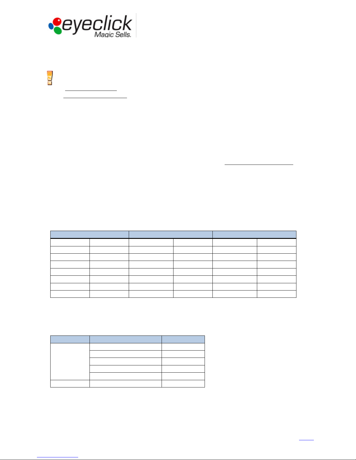
Distance from unit to floor
Expected Image WIDTH
Expected Image HEIGHT
1.5m
5 Ft
125-150 cm
50"-60"
95-110 cm
37"-43"
2m
6.5 Ft
160-190 cm
63"-75"
120-140 cm
47"-55"
2.5m
8 Ft
195-230 cm
77"-90"
145-175 cm
57" - 70"
3m
10 Ft
230-270 cm
90" - 106"
175-205 cm
70" - 80"
3.5m
11.5 Ft
265-310 cm
105" - 122"
200-230 cm
78" – 90"
4m
13 Ft
300-350 cm
118" – 138"
225-265 cm
90" – 105"
4.5m
15 Ft
330-390 cm
130" – 154"
250-295 cm
98"-116"
5m
16.5 Ft
370-435 cm
145" – 170"
275-325 cm
110" – 130"
Table shape
Distance from unit to table
Max table size
Rectangular
120 cm
85 x 110 cm
140 cm
90 x 120 cm
170 cm
110 x 145 cm
200 cm
125 x 165 cm
225 cm
140 x 180 cm
Round
140-225 cm
90-130 cm Ø
EyePlay device installation
Working conditions
Recommended conditions for EyePlay operation are:
- Ambient temperature: 0-35⁰C / 32-95⁰F
- Unit height above sea level: 0-1500m / 0-4900 Ft
In case the installation takes place in a location higher than 1500 meters above sea level or in an ambient
temperature of above 35⁰C / 95⁰F, or in an extremely humid environment - the projector’s working mode should
be set to “High Altitude” (Projector Menu - System Setup: Advanced).
Choosing installation spot
Choosing good installation spot will assure placing the play area in a perfect spot along with providing easy access
for installation and technical service. When choosing the correct spot, please consider the following points:
1. Playground shall be projected to the center of the play area / the center of table. Floor image should be
adjusted to the largest possible projection size (or according to client’s request).
2. Bottom part of image should be facing the entrance to the playground area / table approach.
3. No ventilation ducts, sprinklers, cables or light fixtures should interfere with the unit installation or service
access.
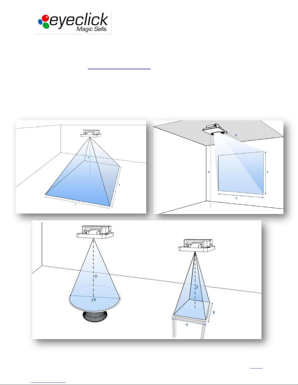
Calculating expected image size (note that the unit's height is ~30 cm / 1Ft)
Floor unit
Table unit
Table units can be used to projects on round, square and rectangular tables.
Long tables can have several interactive areas.
Please see recommended dimensions of tables vs. installation heights:
Guidebook for Technical Partners - All rights reserved, EyeClick Ltd
9
Ver 1.04 – August 6, 2015
Contents
Preparing the device for installation
The EyePlay device comes mostly assembled and houses all components, for easy installation and operation.
Unpacking
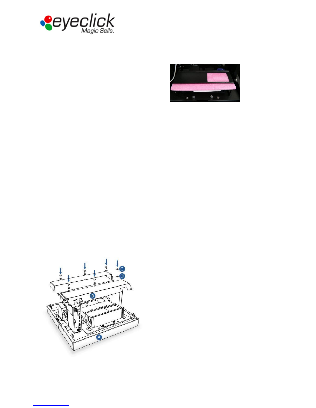
Once removing the EyePlay System from the box,
Please remove the pink protective pad above the projector:
Check cable connections between all components:
1. Connect keyboard’s dongle to a USB 2 port (located in keyboard box)
2. Connect WiFi antenna (located in keyboard box).
3. Verify Motion detection sensor is connected to a USB 2 port.
4. Verify proper VGA/HDMI connection from computer to projector.
5. Verify proper USB-Serial cable + X-Serial Cable [RS-232] connection from computer to projector.
6. Verify proper audio connection - RCA to 3.5mm stereo cable from computer to audio amplifier.
7. Verify proper speakers connection - two sets of exposed cables per speaker: Each cable pair is connected
to a speaker. Each speaker has a “Positive” and a “Negative” connector.
Check power connectors
The unit operates at a full range of 110-240V, with a total power consumption of 352.25W at 7.55A.
There are three devices connected to the power strip: the projector, the computer and the amplifier’s PSU
Check all female connectors (C14 or C5) are plugged to their respective device (projector, computer and amplifier’s
PSU)
Check all male connectors (C13) are plugged to the power strip.
Check main power cable connection from the power strip to main electrical outlet.
Connecting anti-dust top covers to the EyePlay device
The EyePlay unit comes with top cover made out of two parts. Its purpose is to reduce dust particles falling into the
projector’s and computer’s vents. Secure both parts to the top of the bridge using six M4 screws and washers.
Anti-dust covers
Guidebook for Technical Partners - All rights reserved, EyeClick Ltd
Ver 1.04 – August 6, 2015
10
Contents
Drop Ceiling Installation
Installing EyePlay Device
Preparing Equipment for Installation
Coming prepared with the correct hardware and tools will save you time, and guarantee a faster and more
successful installation at the customer’s location. Items required for installation: Drill for cement, extension cord,
tool box including Allen/Hex key set, ladder (or lift) and mounting hardware as per the technicians professional
decision after site survey.
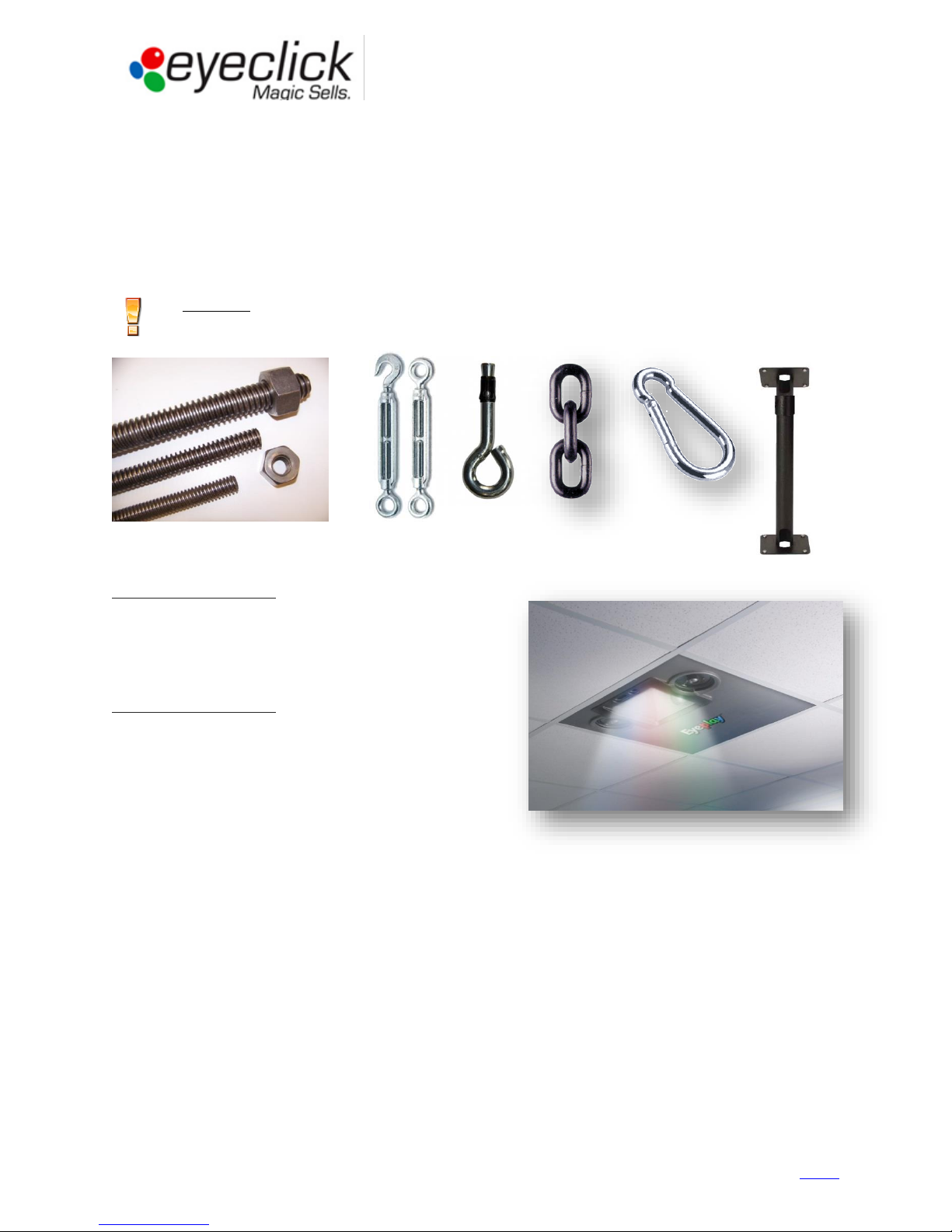
The anchorage must be able to carry a total of 60 KG/130 Lbs minimum. You may use bolts and chains,
threaded rods or mounting poles. Make sure mounting hardware is certified and complies with
international safety regulations:
A Drop Ceiling Installation – when the ceiling is made of tiles
or plaster, suspended from the cement ceiling. In this case
the EyePlay System replaces one of the tiles, and is
concealed in the drop ceiling. It’s hung by chains or
threaded rods to the real concrete ceiling and only
supported by the drop ceiling.
A Stand-Alone Installation – when the EyePlay System is
bolted to the actual ceiling using a mounting pole, and hangs
exposed from the ceiling.
You will need to verify with the client the type of ceiling they
have prior to installation day in order to prepare your
hardware and equipment accordingly. Additional hardware
and tools as mounting poles, concrete bolts, chains, drills,
screw drivers are not provided by EyeClick.
The weight of the EyePlay System is around 17 kg/37 lbs. You will need to provide sleeve anchor bolts, and screws
capable of bearing three times the weight of this load. The EyePlay unit dimensions are 612mm X 612mm X
290mm / 24” X 24” X 11.5”, identical to one ceiling tile. The outer size can be reduced by 15mm/0.6” if needed, by
removing the external cover (when installing into a drop ceiling).
Installation height will affect the image size, note that the maximal possible distance from the interactive surface
to the EyePlay device is 5 meters / 16.5 ft. larger distance will result in interaction problem.
Guidebook for Technical Partners - All rights reserved, EyeClick Ltd
11
Ver 1.04 – August 6, 2015
Contents
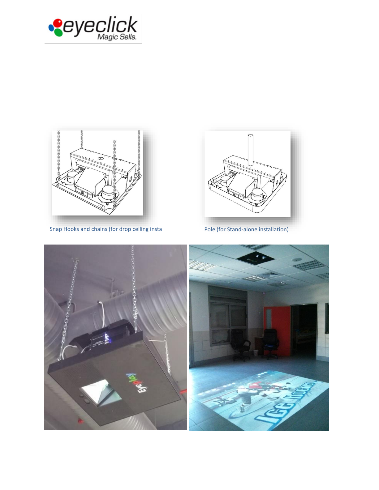
Snap Hooks and chains (for drop ceiling installation)
Pole (for Stand-alone installation)
Installing the EyePlay device
Make sure you have the necessary hardware to hook the device to the ceiling, taking into consideration the weight
of the EyePlay System.
1. Secure four anchoring points as bolts, threaded rods or a single mounting pole to the concrete ceiling.
2. Slowly fit the unit on top the internal frame of the ceiling opening.
3. Attach the system to the shackles and tighten the turnbuckles until it is entirely held on the real ceiling.
4. Connect the power and internet cables.
5. Connect ground cable if there is no ground connection within the power cable.
Guidebook for Technical Partners - All rights reserved, EyeClick Ltd
12
Ver 1.04 – August 6, 2015
Contents
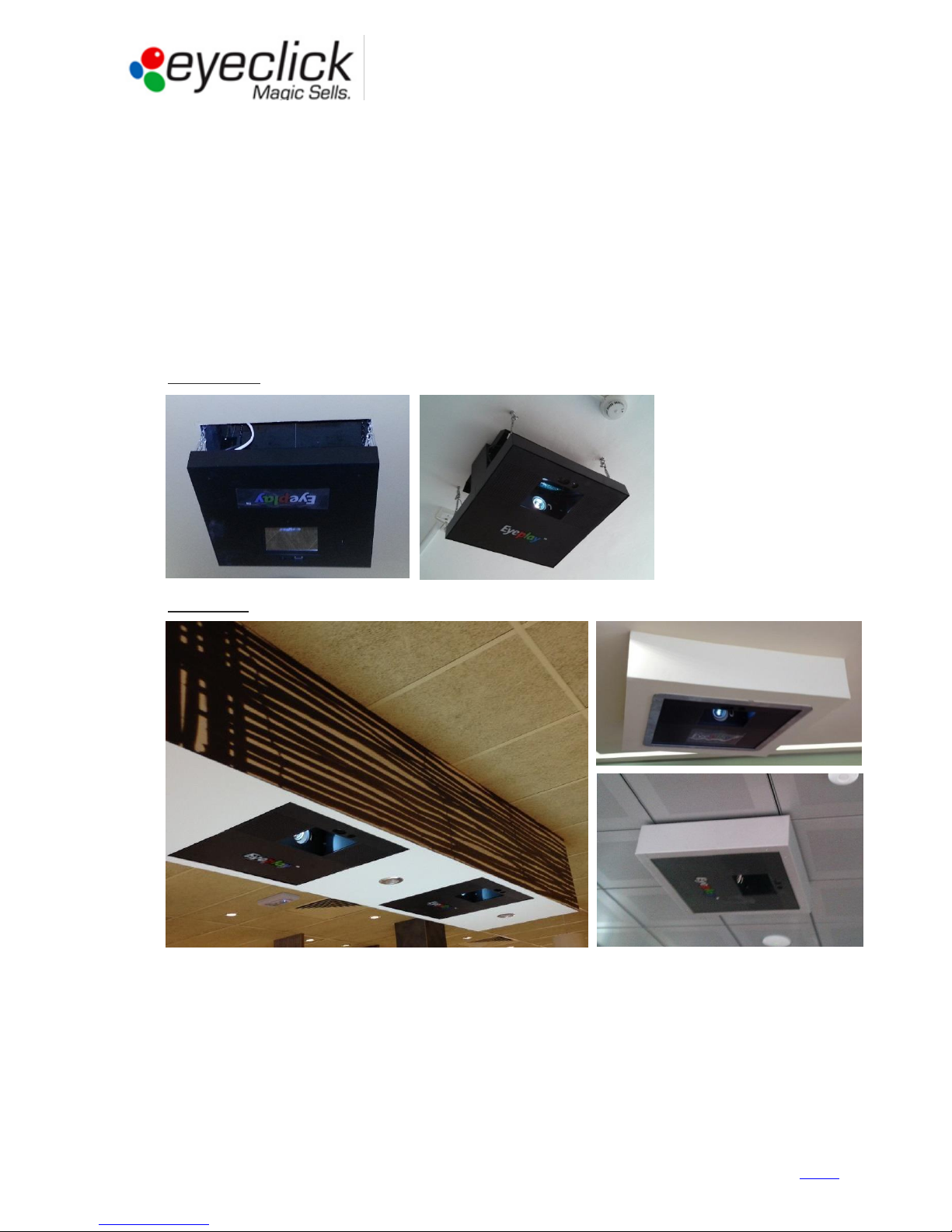
Cabinet
In cases when a unit is installed lower than ceiling level, an aesthetic cabinet will be required.
Such cases can be:
1. Short distance between the real and the false ceiling (device cannot fully fit in the free space).
2. Projected image size is required to be below minimal zoom (small play area with high ceiling).
3. Higher image quality is required, obtained by lowering the unit (table units).
The solution in such cases is obtained by constructing aesthetic side panels (from wood, plaster or other similar
material). One of these sides should allow support access.
Please see examples:
Before cabinet
With cabinet
Guidebook for Technical Partners - All rights reserved, EyeClick Ltd
13
Ver 1.04 – August 6, 2015
Contents
 Loading...