

Page 1

Motion Control Engineering, Inc.
11380 White Rock Road
Rancho Cordova, CA 95742
voice 916 463 9200
fax 916 463 9201
www.mceinc.com
Motion 4000 Traction Elevator Controller
V8.xx software
Manual # 42-02-2P24, Rev B7, May 2013
Page 2

Copyright
© 2013, Motion Control Engineering. All Rights Reserved.
This document may not be reproduced, electronically or mechanically, in whole or in part, without
written permission from Motion Control Engineering.
Trademarks
All trademarks or registered product names appearing in this document are the exclusive property
of the respective owners.
Warning and Disclaimer
Although every effort has been made to make this document as complete and accurate as possible,
Motion Control Engineering and the document authors, publishers, distributors, and
representatives have neither liability nor responsibility for any loss or damage arising from
information contained in this document or from informational errors or omissions. Information
contained in this document shall not be deemed to constitute a commitment to provide service,
equipment, or software by Motion Control Engineering or the document authors, publishers,
distributors, or representatives.
Limited Warranty
Motion Control Engineering (manufacturer) warrants its products for a period of 15 months from
the date of shipment from its factory to be free from defects in workmanship and materials. Any
defect appearing more than 15 months from the date of shipment from the factory shall be
deemed to be due to ordinary wear and tear. Manufacturer, however, assumes no risk or liability for
results of the use of the products purchased from it, including, but without limiting the generality
of the forgoing: (1) The use in combination with any electrical or electronic components, circuits,
systems, assemblies or any other material or equipment (2) Unsuitability of this product for use in
any circuit, assembly or environment. Purchasers’ rights under this warranty shall consist solely of
requiring the manufacturer to repair, or in manufacturer's sole discretion, replace free of charge,
F.O.B. factory, any defective items received at said factory within the said 15 months and
determined by manufacturer to be defective. The giving of or failure to give any advice or
recommendation by manufacturer shall not constitute any warranty by or impose any liability upon
the manufacturer. This warranty constitutes the sole and exclusive remedy of the purchaser and
the exclusive liability of the manufacturer, AND IN LIEU OF ANY AND ALL OTHER WARRANTIES,
EXPRESSED, IMPLIED, OR STATUTORY AS TO MERCHANTABILITY, FITNESS, FOR PURPOSE SOLD,
DESCRIPTION, QUALITY PRODUCTIVENESS OR ANY OTHER MATTER. In no event will the
manufacturer be liable for special or consequential damages or for delay in performance of this
warranty.
Products that are not manufactured by MCE (such as drives, CRTs, modems, printers, etc.) are not
covered under the above warranty terms. MCE, however, extends the same warranty terms that
the original manufacturer of such equipment provide with their product (refer to the warranty
terms for such products in their respective manual).
Page 3

End User License Agreement
This End User License Agreement (“Agreement”) grants you the right to use the software contained in this product (the “Software”) subject to the following restrictions: You may not: (i) copy
the Software, except for archive purposes consistent with your standard archive procedures; (ii)
transfer the Software to a third party apart from the entire product; (iii) modify, decompile, disassemble, reverse engineer or otherwise attempt to derive the source code of the Software; (iv)
export the Software or underlying technology in contravention of applicable U.S. and foreign
export laws and regulations; and (v) use the Software other than in connection with operation of
the product.
“LICENSOR'S SUPPLIERS DO NOT MAKE OR PASS ON TO END USER OR ANY OTHER THIRD PARTY,
ANY EXPRESS, IMPLIED OR STATUTORY WARRANTY OR REPRESENTATION ON BEHALF OF SUCH
SUPPLIERS, INCLUDING BUT NOT LIMITED TO THE IMPLIED WARRANTIES OF NON-INFRINGEMENT, TITLE, MERCHANTABILITY OR FITNESS FOR A PARTICULAR PURPOSE.”
Page 4
Important Precautions and Useful Information
Danger
Caution
Note
Danger
This preface contains information that will help you understand and safely maintain MCE
equipment. We strongly recommend you review this preface and read this manual before
installing, adjusting, or maintaining Motion Control Engineering equipment. This preface discusses:
• Safety and Other Symbol Meanings
• Safety Precautions
• Environmental Considerations
•In This Guide
Safety and Other Symbol Meanings
This manual symbol is used to alert you to procedures, instructions, or situations which, if not done
properly, might result in personal injury or substantial equipment damage.
This manual symbol is used to alert you to procedures, instructions, or situations which, if not done
properly, might result in equipment damage.
This manual symbol is used to alert you to instructions or other immediately helpful information.
Safety Precautions
This equipment is designed to comply with ASME A17.1, National Electrical Code, CE, and CAN/
CSA-B44.1/ASME-A17.5 and must be installed by a qualified contractor. It is the responsibility of the
contractor to make sure that the final installation complies with all local codes and is installed in a
safe manner.
This equipment is suitable for use on a circuit capable of delivering not more than 10,000 rms symmetrical amperes, 600 volts maximum. The three-phase AC power supply to the Drive Isolation
Transformer used with this equipment must originate from a fused disconnect switch or circuit
breaker sized in conformance to all applicable national, state, and local electrical codes in order to
provide the necessary motor branch circuit protection for the Drive Unit and motor. Incorrect motor
branch circuit protection will void the warranty and may create a hazardous condition.
Proper grounding is vitally important to safe and successful operation. Bring your ground wire to the
system subplate. You must choose the proper conductor size and minimize the resistance to ground
by using the shortest possible routing. See National Electrical Code Article 250 or the applicable local
electrical code.
Page 5

Before applying power to the controller, physically check all the power resistors and other components located in the resistor cabinet and inside the controller. Components loosened during shipment may cause damage.
For proper operation of the AC Drive Unit in your controller, you must make sure that: 1) A direct
solid ground is provided in the machine room to properly ground the controller and motor. Indirect
grounds such as the building structure or a water pipe may not provide proper grounding and could
act as an antenna to radiate RFI noise, thus disturbing sensitive equipment in the building. Improper
grounding may also render any RFI filter ineffect ive. 2) The incomi ng power to the controlle r and the
outgoing power wires to the motor are in their respective, separate, grounded conduits.
This equipment may contain voltages as high as 1000 volts. Use extreme caution. Do not touch any
components, resistors, circuit boards, power devices, or electrical connections without ensuring that
high voltage is not present.
Environmental Considerations
• Keep the machine room clean.
•Controllers are generally in NEMA 1 enclosures.
• Do not install the controller in a dusty area.
• Do not install the controller in a carpeted area.
• Keep room temperature between 32 and 104 degrees F (0 to 40 degrees C).
• Prevent condensation on the equipment.
• Do not install the controller in a hazardous location or where excessive amounts of
vapors or chemical fumes may be present.
• Make certain that power line fluctuations are within plus or minus 10% of proper value.
Air Conditioned Equipment Cabinets
If your control or group enclosure is equipped with an air conditioning unit, it is very important
to observe the following precautions. (Failure to do so can result in moisture damage to electrical components.)
• Maintain the integrity of the cabinet by using sealed knockouts and sealing any holes
made during installation.
• Do not run the air conditioning while the cabinet doors are open.
• If you turn the air conditioner off while it is running, wait at least five minutes before
restarting it. Otherwise, the compressor may be damaged.
• Observe the recommended thermostat setting (75 degrees) and follow recommended
maintenance schedules.
• Make certain that the air conditioning drain tube remains clear to avoid water accumulation in the unit.
Page 6

In This Manual:
This manual is the installation, adjustment, and troubleshooting guide for the Motion 4000
traction controller. When viewed online as a pdf file, hyperlinks (buttons or blue text) link to
related topics and informational websites. The manual includes:
• Contents: Table of Contents. When viewed online as a pdf file, hyperlinks in the Contents
link to the associated topic in the body of the manual.
• Section 1. General Information: System description; operating modes
• Section 2. Installation
• Section 3. Final Adjustments
• Section 4. User Interface
• Section 5. Troubleshooting
•Appendix
• Index: Alphabetical index to help you find information in the manual. When viewed
online as a pdf file, index entry page references are hyperlinks to the associated information in the body of the manual.
Page 7

Contents
Section 1. Motion 4000 Traction Elevator Control
In this section . . . . . . . . . . . . . . . . . . . . . . . . . . . . . . . . . . . . . . . . . . . . . . . . . . . . . . 1-1
Motion 4000 Traction Elevator Control Overview . . . . . . . . . . . . . . . . . . . . . . . 1-2
System Features . . . . . . . . . . . . . . . . . . . . . . . . . . . . . . . . . . . . . . . . . . . . . . . . . . . . 1-3
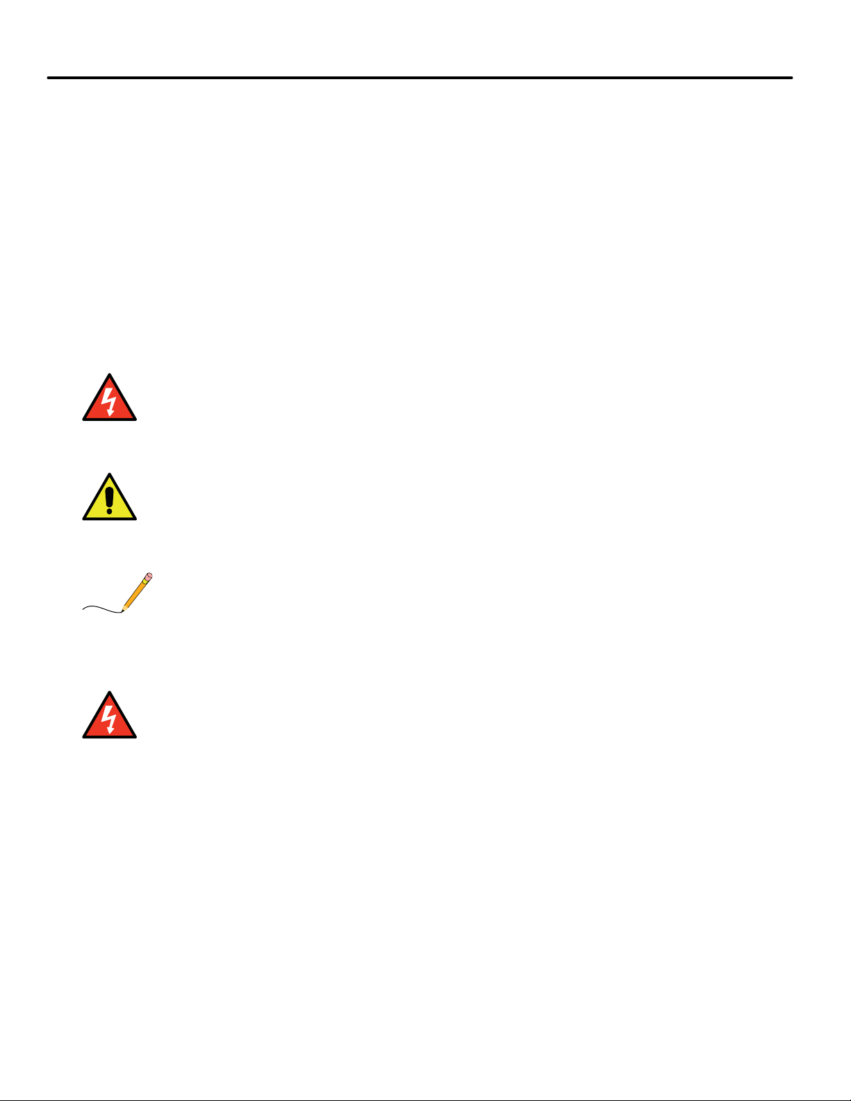
System Component Descriptions . . . . . . . . . . . . . . . . . . . . . . . . . . . . . . . . . . . . . . 1-5
Controller Circuit Boards . . . . . . . . . . . . . . . . . . . . . . . . . . . . . . . . . . . . . . . . . . . . . . . . . . 1-5
Hand-Held User Interface . . . . . . . . . . . . . . . . . . . . . . . . . . . . . . . . . . . . . . . . . . . . . . . . . 1-6
Car . . . . . . . . . . . . . . . . . . . . . . . . . . . . . . . . . . . . . . . . . . . . . . . . . . . . . . . . . . . . . . . . . . . . . . . 1-6
Landing and Positioning. . . . . . . . . . . . . . . . . . . . . . . . . . . . . . . . . . . . . . . . . . . . . . . . . . . 1-6
Load Weigher . . . . . . . . . . . . . . . . . . . . . . . . . . . . . . . . . . . . . . . . . . . . . . . . . . . . . . . . . . . . 1-7
Cartop Box . . . . . . . . . . . . . . . . . . . . . . . . . . . . . . . . . . . . . . . . . . . . . . . . . . . . . . . . . . . . . . 1-7
Hoistway . . . . . . . . . . . . . . . . . . . . . . . . . . . . . . . . . . . . . . . . . . . . . . . . . . . . . . . . . . . . . . . . . . 1-8
Motion 4000 Specific Traveler Cable . . . . . . . . . . . . . . . . . . . . . . . . . . . . . . . . . . . . . . . . 1-8
Operating Mode Descriptions . . . . . . . . . . . . . . . . . . . . . . . . . . . . . . . . . . . . . . . .1-9
Normal Operation . . . . . . . . . . . . . . . . . . . . . . . . . . . . . . . . . . . . . . . . . . . . . . . . . . . . . . . . . . 1-9
Inspection Operation . . . . . . . . . . . . . . . . . . . . . . . . . . . . . . . . . . . . . . . . . . . . . . . . . . . . . . . . 1-9
Cartop Inspection . . . . . . . . . . . . . . . . . . . . . . . . . . . . . . . . . . . . . . . . . . . . . . . . . . . . . . . . 1-9
Mode Entry. . . . . . . . . . . . . . . . . . . . . . . . . . . . . . . . . . . . . . . . . . . . . . . . . . . . . . . . . . . . . . . . . . . 1-9
In Car Inspection . . . . . . . . . . . . . . . . . . . . . . . . . . . . . . . . . . . . . . . . . . . . . . . . . . . . . . . . 1-10
Mode Entry. . . . . . . . . . . . . . . . . . . . . . . . . . . . . . . . . . . . . . . . . . . . . . . . . . . . . . . . . . . . . . . . . . 1-10
Hoistway Access Inspection . . . . . . . . . . . . . . . . . . . . . . . . . . . . . . . . . . . . . . . . . . . . . . . 1-10
Mode Entry. . . . . . . . . . . . . . . . . . . . . . . . . . . . . . . . . . . . . . . . . . . . . . . . . . . . . . . . . . . . . . . . . . 1-10
Machine Room Inspection . . . . . . . . . . . . . . . . . . . . . . . . . . . . . . . . . . . . . . . . . . . . . . . . 1-10
Mode Entry. . . . . . . . . . . . . . . . . . . . . . . . . . . . . . . . . . . . . . . . . . . . . . . . . . . . . . . . . . . . . . . . . . 1-10
Attendant Operation . . . . . . . . . . . . . . . . . . . . . . . . . . . . . . . . . . . . . . . . . . . . . . . . . . . . . . . . 1-11
Mode Entry. . . . . . . . . . . . . . . . . . . . . . . . . . . . . . . . . . . . . . . . . . . . . . . . . . . . . . . . . . . . . 1-11
Independent Service . . . . . . . . . . . . . . . . . . . . . . . . . . . . . . . . . . . . . . . . . . . . . . . . . . . . . . . . 1-11
Mode Entry. . . . . . . . . . . . . . . . . . . . . . . . . . . . . . . . . . . . . . . . . . . . . . . . . . . . . . . . . . . . . 1-11
Sabbath Operation . . . . . . . . . . . . . . . . . . . . . . . . . . . . . . . . . . . . . . . . . . . . . . . . . . . . . . . . . .1-12
Emergency Medical Operation . . . . . . . . . . . . . . . . . . . . . . . . . . . . . . . . . . . . . . . . . . . . . . . .1-12
Hospital Service . . . . . . . . . . . . . . . . . . . . . . . . . . . . . . . . . . . . . . . . . . . . . . . . . . . . . . . . . . . .1-13
Seismic Operation . . . . . . . . . . . . . . . . . . . . . . . . . . . . . . . . . . . . . . . . . . . . . . . . . . . . . . . . . .1-13
Mode Exit . . . . . . . . . . . . . . . . . . . . . . . . . . . . . . . . . . . . . . . . . . . . . . . . . . . . . . . . . . . . . . 1-13
Modifiers. . . . . . . . . . . . . . . . . . . . . . . . . . . . . . . . . . . . . . . . . . . . . . . . . . . . . . . . . . . . . . . 1-13
Fire Service Operation . . . . . . . . . . . . . . . . . . . . . . . . . . . . . . . . . . . . . . . . . . . . . . . . . . . . . . .1-14
Emergency Power Operation . . . . . . . . . . . . . . . . . . . . . . . . . . . . . . . . . . . . . . . . . . . . . . . . .1-14
Generator Backup . . . . . . . . . . . . . . . . . . . . . . . . . . . . . . . . . . . . . . . . . . . . . . . . . . . . . . . 1-14
TAPS Backup . . . . . . . . . . . . . . . . . . . . . . . . . . . . . . . . . . . . . . . . . . . . . . . . . . . . . . . . . . . 1-14
Car Recall . . . . . . . . . . . . . . . . . . . . . . . . . . . . . . . . . . . . . . . . . . . . . . . . . . . . . . . . . . . . . . . . .1-15
Capture for Test . . . . . . . . . . . . . . . . . . . . . . . . . . . . . . . . . . . . . . . . . . . . . . . . . . . . . . . . . . . .1-15
Test Mode . . . . . . . . . . . . . . . . . . . . . . . . . . . . . . . . . . . . . . . . . . . . . . . . . . . . . . . . . . . . . . . . .1-15
Monitoring and Control Options . . . . . . . . . . . . . . . . . . . . . . . . . . . . . . . . . . . . . 1-16
i
Page 8

Section 2. Installation
In this Section . . . . . . . . . . . . . . . . . . . . . . . . . . . . . . . . . . . . . . . . . . . . . . . . . . . . . . 2-1
Safety . . . . . . . . . . . . . . . . . . . . . . . . . . . . . . . . . . . . . . . . . . . . . . . . . . . . . . . . . . . . .2-2
Personal Safety . . . . . . . . . . . . . . . . . . . . . . . . . . . . . . . . . . . . . . . . . . . . . . . . . . . . . . . . . . . . . 2-2
Equipment Safety . . . . . . . . . . . . . . . . . . . . . . . . . . . . . . . . . . . . . . . . . . . . . . . . . . . . . . . . . . . 2-3
Preparation . . . . . . . . . . . . . . . . . . . . . . . . . . . . . . . . . . . . . . . . . . . . . . . . . . . . . . . .2-3
Electrical Noise . . . . . . . . . . . . . . . . . . . . . . . . . . . . . . . . . . . . . . . . . . . . . . . . . . . . . . . . . . . . . 2-4
EMI/RFI . . . . . . . . . . . . . . . . . . . . . . . . . . . . . . . . . . . . . . . . . . . . . . . . . . . . . . . . . . . . . . . . 2-4
Recommended Tools and Test Equipment . . . . . . . . . . . . . . . . . . . . . . . . . . . . . . . . . . . . . . 2-4
MCE Wiring Prints . . . . . . . . . . . . . . . . . . . . . . . . . . . . . . . . . . . . . . . . . . . . . . . . . .2-5
Drawing Number Format . . . . . . . . . . . . . . . . . . . . . . . . . . . . . . . . . . . . . . . . . . . . . . . . . . . . 2-5
Nomenclature . . . . . . . . . . . . . . . . . . . . . . . . . . . . . . . . . . . . . . . . . . . . . . . . . . . . . . . . . . . . . . 2-5
Power Nomenclature. . . . . . . . . . . . . . . . . . . . . . . . . . . . . . . . . . . . . . . . . . . . . . . . . . . . . . 2-5
Controller Installation . . . . . . . . . . . . . . . . . . . . . . . . . . . . . . . . . . . . . . . . . . . . . .2-6
Controller Wiring Guidelines . . . . . . . . . . . . . . . . . . . . . . . . . . . . . . . . . . . . . . . . . . . . . . . . . 2-7
Proper Ground . . . . . . . . . . . . . . . . . . . . . . . . . . . . . . . . . . . . . . . . . . . . . . . . . . . . . . . . . . . . . 2-7
Check for Shorts to Ground . . . . . . . . . . . . . . . . . . . . . . . . . . . . . . . . . . . . . . . . . . . . . . . . . . 2-9
AC Power Connections . . . . . . . . . . . . . . . . . . . . . . . . . . . . . . . . . . . . . . . . . . . . .2-10
Brake Module . . . . . . . . . . . . . . . . . . . . . . . . . . . . . . . . . . . . . . . . . . . . . . . . . . . . . . . . . . . . . . . .2-10
Power Check . . . . . . . . . . . . . . . . . . . . . . . . . . . . . . . . . . . . . . . . . . . . . . . . . . . . . . . . . . . . . . 2-10
Motor, Brake, and Encoder Connection . . . . . . . . . . . . . . . . . . . . . . . . . . . . . . . 2-11
Motor Connection . . . . . . . . . . . . . . . . . . . . . . . . . . . . . . . . . . . . . . . . . . . . . . . . . . . . . . . . . .2-11
Insulation Breakdown Test. . . . . . . . . . . . . . . . . . . . . . . . . . . . . . . . . . . . . . . . . . . . . . . . 2-11
Motor Wiring . . . . . . . . . . . . . . . . . . . . . . . . . . . . . . . . . . . . . . . . . . . . . . . . . . . . . . . . . . . 2-11
MRL or Extended Motor Cables. . . . . . . . . . . . . . . . . . . . . . . . . . . . . . . . . . . . . . . . . . . . 2-11
Brake Connection . . . . . . . . . . . . . . . . . . . . . . . . . . . . . . . . . . . . . . . . . . . . . . . . . . . . . . . . . . 2-12
Standard Brake . . . . . . . . . . . . . . . . . . . . . . . . . . . . . . . . . . . . . . . . . . . . . . . . . . . . . . . . . 2-12
Brake Module. . . . . . . . . . . . . . . . . . . . . . . . . . . . . . . . . . . . . . . . . . . . . . . . . . . . . . . . . . . 2-12
Brake Mechanics . . . . . . . . . . . . . . . . . . . . . . . . . . . . . . . . . . . . . . . . . . . . . . . . . . . . . . . . . . 2-12
Velocity Encoder Installation and Wiring . . . . . . . . . . . . . . . . . . . . . . . . . . . . . . . . . . . . . . 2-13
Encoder Wiring . . . . . . . . . . . . . . . . . . . . . . . . . . . . . . . . . . . . . . . . . . . . . . . . . . . . . . . . . 2-13
Emergency Brake Installation . . . . . . . . . . . . . . . . . . . . . . . . . . . . . . . . . . . . . . .2-14
Resetting the Rope Gripper . . . . . . . . . . . . . . . . . . . . . . . . . . . . . . . . . . . . . . . . . . . . . . . . . 2-14
Initial Power Up . . . . . . . . . . . . . . . . . . . . . . . . . . . . . . . . . . . . . . . . . . . . . . . . . . .2-14
Often Used Procedures . . . . . . . . . . . . . . . . . . . . . . . . . . . . . . . . . . . . . . . . . . . . . . . . . . . . . 2-15
How to check Car Speed: . . . . . . . . . . . . . . . . . . . . . . . . . . . . . . . . . . . . . . . . . . . . . . . . . 2-15
How to place the car on Inspection Mode Fault Bypass: . . . . . . . . . . . . . . . . . . . . . . . 2-15
How to place the car on Automatic Mode Fault Bypass:. . . . . . . . . . . . . . . . . . . . . . . . 2-15
How to change TORQMAX F5 Drive parameter settings: . . . . . . . . . . . . . . . . . . . . . . 2-16
How to change Magnetek Drive parameter settings:. . . . . . . . . . . . . . . . . . . . . . . . . . . 2-16
How to access/set the F7 parameters:. . . . . . . . . . . . . . . . . . . . . . . . . . . . . . . . . . . . . . . 2-16
Important . . . . . . . . . . . . . . . . . . . . . . . . . . . . . . . . . . . . . . . . . . . . . . . . . . . . . . . . . . . . . . . . . . . 2-16
How to Reset Excessive Faults . . . . . . . . . . . . . . . . . . . . . . . . . . . . . . . . . . . . . . . . . . . . . 2-16
ii Manual # 42-02-2P24 5/20/13
Page 9

Auto Tuning and Encoder Data Loading . . . . . . . . . . . . . . . . . . . . . . . . . . . . . . . 2-17
Torqmax/Keb F5 Drive Introduction . . . . . . . . . . . . . . . . . . . . . . . . . . . . . . . . . . . . . . . . . .2-17
Digital Operator . . . . . . . . . . . . . . . . . . . . . . . . . . . . . . . . . . . . . . . . . . . . . . . . . . . . . . . . . 2-17
Keypad Operation . . . . . . . . . . . . . . . . . . . . . . . . . . . . . . . . . . . . . . . . . . . . . . . . . . . . . . . 2-18
Clear Error . . . . . . . . . . . . . . . . . . . . . . . . . . . . . . . . . . . . . . . . . . . . . . . . . . . . . . . . . . . . . 2-18
TorqMax/KEB Drive Operation Overview . . . . . . . . . . . . . . . . . . . . . . . . . . . . . . . . . . . 2-20
Drive Motor/Encoder Setup Overview . . . . . . . . . . . . . . . . . . . . . . . . . . . . . . . . . . . . . . 2-20
Check Correct Motor/Control. . . . . . . . . . . . . . . . . . . . . . . . . . . . . . . . . . . . . . . . . . . . . . . . . . .2-20
Check Control Mode . . . . . . . . . . . . . . . . . . . . . . . . . . . . . . . . . . . . . . . . . . . . . . . . . . . . . . . . . .2-20
Learn or Enter Motor or Encoder Data . . . . . . . . . . . . . . . . . . . . . . . . . . . . . . . . . . . . . . . . . . . 2-21
Auto-tuning AC Induction Motors to the F5 Drive . . . . . . . . . . . . . . . . . . . . . . . . . . . . 2-21
Manual Induction Motor Parameter Entry. . . . . . . . . . . . . . . . . . . . . . . . . . . . . . . . . . . 2-22
The Drive Manual . . . . . . . . . . . . . . . . . . . . . . . . . . . . . . . . . . . . . . . . . . . . . . . . . . . . . . . 2-22
Loading Data from PM AC Encoder to the F5 Drive . . . . . . . . . . . . . . . . . . . . . . . . . . . 2-23
Learning Encoder Data From PM Machines . . . . . . . . . . . . . . . . . . . . . . . . . . . . . . . . . 2-23
Setting the Drive to Run Mode. . . . . . . . . . . . . . . . . . . . . . . . . . . . . . . . . . . . . . . . . . . . . 2-23
Magnetek AC Drive Introduction . . . . . . . . . . . . . . . . . . . . . . . . . . . . . . . . . . . . . . . . . . . . . 2-24
Digital Operator . . . . . . . . . . . . . . . . . . . . . . . . . . . . . . . . . . . . . . . . . . . . . . . . . . . . . . . . . 2-24
Keypad Operation . . . . . . . . . . . . . . . . . . . . . . . . . . . . . . . . . . . . . . . . . . . . . . . . . . . . . . . 2-24
Clear Fault . . . . . . . . . . . . . . . . . . . . . . . . . . . . . . . . . . . . . . . . . . . . . . . . . . . . . . . . . . . . . 2-24
Magnetek Drive Operation Overview . . . . . . . . . . . . . . . . . . . . . . . . . . . . . . . . . . . . . . . 2-25
Operator (HPV600/600PM/900/900PM) . . . . . . . . . . . . . . . . . . . . . . . . . . . . . . . . . . . . . . . 2-25
Operator (HPV 900II). . . . . . . . . . . . . . . . . . . . . . . . . . . . . . . . . . . . . . . . . . . . . . . . . . . . . . . . .2-25
Cover (HPV 900/900PM). . . . . . . . . . . . . . . . . . . . . . . . . . . . . . . . . . . . . . . . . . . . . . . . . . . . . .2-26
Drive Motor/Encoder Setup Overview . . . . . . . . . . . . . . . . . . . . . . . . . . . . . . . . . . . . . . 2-26
Auto-tuning AC Motors to the Magnetek Drive . . . . . . . . . . . . . . . . . . . . . . . . . . . . . . . 2-27
Tuning Motor No-Load Current (HPV 600/900/900II Only). . . . . . . . . . . . . . . . . . . . . . . . 2-27
Tuning Motor Flux Saturation Curve (HPV 600/900/900II Only). . . . . . . . . . . . . . . . . . . . 2-27
Tuning Motor Rated RPM (HPV 600/900/900II Only). . . . . . . . . . . . . . . . . . . . . . . . . . . . .2-27
Determining System Inertia . . . . . . . . . . . . . . . . . . . . . . . . . . . . . . . . . . . . . . . . . . . . . . . . . . . . 2-27
The Drive Manual . . . . . . . . . . . . . . . . . . . . . . . . . . . . . . . . . . . . . . . . . . . . . . . . . . . . . . . 2-27
Set Up for Construction Operation . . . . . . . . . . . . . . . . . . . . . . . . . . . . . . . . . . 2-28
Minimal Requirements . . . . . . . . . . . . . . . . . . . . . . . . . . . . . . . . . . . . . . . . . . . . . . . . . . . . . 2-28
Jumper Requirements. . . . . . . . . . . . . . . . . . . . . . . . . . . . . . . . . . . . . . . . . . . . . . . . . . . . 2-28
Bypassing Faults on Inspection . . . . . . . . . . . . . . . . . . . . . . . . . . . . . . . . . . . . . . . . . . . . 2-29
Resolving Faults. . . . . . . . . . . . . . . . . . . . . . . . . . . . . . . . . . . . . . . . . . . . . . . . . . . . . . . . . 2-29
Speed and Acceleration Control . . . . . . . . . . . . . . . . . . . . . . . . . . . . . . . . . . . . . . . . . . . . . . 2-30
Required Drive Parameter Settings . . . . . . . . . . . . . . . . . . . . . . . . . . . . . . . . . . . . . . . . . . . 2-31
Torqmax F5 AC Drive Parameters. . . . . . . . . . . . . . . . . . . . . . . . . . . . . . . . . . . . . . . . . . 2-31
Magnetek AC Drive Parameters. . . . . . . . . . . . . . . . . . . . . . . . . . . . . . . . . . . . . . . . . . . . 2-36
Required Controller Parameter Settings . . . . . . . . . . . . . . . . . . . . . . . . . . . . . . . . . . . . . . . 2-44
Acceleration and Deceleration Rates. . . . . . . . . . . . . . . . . . . . . . . . . . . . . . . . . . . . . . . . 2-44
Curves Used for Operating Speeds . . . . . . . . . . . . . . . . . . . . . . . . . . . . . . . . . . . . . . . . . 2-44
The F7 Menu. . . . . . . . . . . . . . . . . . . . . . . . . . . . . . . . . . . . . . . . . . . . . . . . . . . . . . . . . . . . 2-45
Important . . . . . . . . . . . . . . . . . . . . . . . . . . . . . . . . . . . . . . . . . . . . . . . . . . . . . . . . . . . . . . . . . . .2-45
Changing Parameters . . . . . . . . . . . . . . . . . . . . . . . . . . . . . . . . . . . . . . . . . . . . . . . . . . . . . . . . .2-45
Next . . . . . . . . . . . . . . . . . . . . . . . . . . . . . . . . . . . . . . . . . . . . . . . . . . . . . . . . . . . . . . . . . . . . . . . .2-45
Select . . . . . . . . . . . . . . . . . . . . . . . . . . . . . . . . . . . . . . . . . . . . . . . . . . . . . . . . . . . . . . . . . . . . . . .2-45
Change. . . . . . . . . . . . . . . . . . . . . . . . . . . . . . . . . . . . . . . . . . . . . . . . . . . . . . . . . . . . . . . . . . . . . .2-45
Move Back. . . . . . . . . . . . . . . . . . . . . . . . . . . . . . . . . . . . . . . . . . . . . . . . . . . . . . . . . . . . . . . . . . .2-45
Saving Changes. . . . . . . . . . . . . . . . . . . . . . . . . . . . . . . . . . . . . . . . . . . . . . . . . . . . . . . . . . . . . . .2-45
iii
Page 10

Controller Motion Parameters . . . . . . . . . . . . . . . . . . . . . . . . . . . . . . . . . . . . . . . . . . . . . 2-46
Using Inspection Stations to Run . . . . . . . . . . . . . . . . . . . . . . . . . . . . . . . . . . . . . . . . . . . . . 2-47
Encoder Polarity (KEB, TorqMAX) . . . . . . . . . . . . . . . . . . . . . . . . . . . . . . . . . . . . . . . . . 2-47
Align Encoder (Magnetek) . . . . . . . . . . . . . . . . . . . . . . . . . . . . . . . . . . . . . . . . . . . . . . . . 2-47
HPV 600/900/900II. . . . . . . . . . . . . . . . . . . . . . . . . . . . . . . . . . . . . . . . . . . . . . . . . . . . . . . . . . 2-47
HPV 600PM . . . . . . . . . . . . . . . . . . . . . . . . . . . . . . . . . . . . . . . . . . . . . . . . . . . . . . . . . . . . . . . . .2-47
HPV 900PM . . . . . . . . . . . . . . . . . . . . . . . . . . . . . . . . . . . . . . . . . . . . . . . . . . . . . . . . . . . . . . . . .2-48
Brake Basics . . . . . . . . . . . . . . . . . . . . . . . . . . . . . . . . . . . . . . . . . . . . . . . . . . . . . . . . . . . . 2-48
Verify Motor Speed, KEB/TorqMAX. . . . . . . . . . . . . . . . . . . . . . . . . . . . . . . . . . . . . . . . 2-49
Verify Motor Speed, Magnetek. . . . . . . . . . . . . . . . . . . . . . . . . . . . . . . . . . . . . . . . . . . . . 2-49
Temporary Run Box Hookup. . . . . . . . . . . . . . . . . . . . . . . . . . . . . . . . . . . . . . . . . . . . . . 2-50
Prepare for Inspection Operation . . . . . . . . . . . . . . . . . . . . . . . . . . . . . . . . . . . . 2-51
Hoistway Safety String . . . . . . . . . . . . . . . . . . . . . . . . . . . . . . . . . . . . . . . . . . . . . . . . . . . . . 2-52
Cartop Safety String . . . . . . . . . . . . . . . . . . . . . . . . . . . . . . . . . . . . . . . . . . . . . . . . . . . . . . . . 2-52
Hoistway Switches . . . . . . . . . . . . . . . . . . . . . . . . . . . . . . . . . . . . . . . . . . . . . . . . . . . . . . . . . 2-52
Virtual/Physical/Unused . . . . . . . . . . . . . . . . . . . . . . . . . . . . . . . . . . . . . . . . . . . . . . . . . 2-52
LS-EDGE. . . . . . . . . . . . . . . . . . . . . . . . . . . . . . . . . . . . . . . . . . . . . . . . . . . . . . . . . . . . . . . . . . . .2-52
Seismic Equipment . . . . . . . . . . . . . . . . . . . . . . . . . . . . . . . . . . . . . . . . . . . . . . . . . . . . . . . . 2-53
Running on Inspection Mode . . . . . . . . . . . . . . . . . . . . . . . . . . . . . . . . . . . . . . . .2-54
Controller Power Up . . . . . . . . . . . . . . . . . . . . . . . . . . . . . . . . . . . . . . . . . . . . . . . . . . . . . . . 2-54
Bypassing Faults on Inspection . . . . . . . . . . . . . . . . . . . . . . . . . . . . . . . . . . . . . . . . . . . . 2-55
Finishing Installation . . . . . . . . . . . . . . . . . . . . . . . . . . . . . . . . . . . . . . . . . . . . . .2-55
Landing/Positioning System . . . . . . . . . . . . . . . . . . . . . . . . . . . . . . . . . . . . . . . .2-56
LS-EDGE . . . . . . . . . . . . . . . . . . . . . . . . . . . . . . . . . . . . . . . . . . . . . . . . . . . . . . . . . . . . . . . . . 2-56
Tape Installation . . . . . . . . . . . . . . . . . . . . . . . . . . . . . . . . . . . . . . . . . . . . . . . . . . . . . . . . 2-57
Top and Bottom Hangers . . . . . . . . . . . . . . . . . . . . . . . . . . . . . . . . . . . . . . . . . . . . . . . . . . . 2-58
Tape Detector Switch . . . . . . . . . . . . . . . . . . . . . . . . . . . . . . . . . . . . . . . . . . . . . . . . . . . . . . . 2-59
Tape Hanging . . . . . . . . . . . . . . . . . . . . . . . . . . . . . . . . . . . . . . . . . . . . . . . . . . . . . . . . . . . . . 2-59
Tape Tension . . . . . . . . . . . . . . . . . . . . . . . . . . . . . . . . . . . . . . . . . . . . . . . . . . . . . . . . . . . . . 2-60
Sensor Installation . . . . . . . . . . . . . . . . . . . . . . . . . . . . . . . . . . . . . . . . . . . . . . . . . . . . . . . . . 2-60
Sensor Alignment . . . . . . . . . . . . . . . . . . . . . . . . . . . . . . . . . . . . . . . . . . . . . . . . . . . . . . . . . . 2-61
Door Zone, Terminal, and ETS Magnets . . . . . . . . . . . . . . . . . . . . . . . . . . . . . . . . . . . . . . . 2-61
Top Terminal and ETS Magnets . . . . . . . . . . . . . . . . . . . . . . . . . . . . . . . . . . . . . . . . . . . 2-63
Bottom Terminal and ETS Magnets . . . . . . . . . . . . . . . . . . . . . . . . . . . . . . . . . . . . . . . . 2-64
Electrical Connection . . . . . . . . . . . . . . . . . . . . . . . . . . . . . . . . . . . . . . . . . . . . . . . . . . . . 2-65
Parameter Settings . . . . . . . . . . . . . . . . . . . . . . . . . . . . . . . . . . . . . . . . . . . . . . . . . . . . . . 2-66
Permanent Magnet Attachment. . . . . . . . . . . . . . . . . . . . . . . . . . . . . . . . . . . . . . . . . . . . 2-66
Indicators . . . . . . . . . . . . . . . . . . . . . . . . . . . . . . . . . . . . . . . . . . . . . . . . . . . . . . . . . . . . . . 2-66
ELGO . . . . . . . . . . . . . . . . . . . . . . . . . . . . . . . . . . . . . . . . . . . . . . . . . . . . . . . . . . . . . . . . . . . . 2-67
Safety String Connection Information . . . . . . . . . . . . . . . . . . . . . . . . . . . . . . . . . . . . . . 2-68
Recommendations. . . . . . . . . . . . . . . . . . . . . . . . . . . . . . . . . . . . . . . . . . . . . . . . . . . . . . . 2-68
Installation . . . . . . . . . . . . . . . . . . . . . . . . . . . . . . . . . . . . . . . . . . . . . . . . . . . . . . . . . . . . . 2-69
Tape End Pieces . . . . . . . . . . . . . . . . . . . . . . . . . . . . . . . . . . . . . . . . . . . . . . . . . . . . . . . . . . . . . .2-70
Hanging Tape . . . . . . . . . . . . . . . . . . . . . . . . . . . . . . . . . . . . . . . . . . . . . . . . . . . . . . . . . . . . . . . .2-70
Sensor Mounting . . . . . . . . . . . . . . . . . . . . . . . . . . . . . . . . . . . . . . . . . . . . . . . . . . . . . . . . . . . . .2-72
Hoistway Learn, Elgo . . . . . . . . . . . . . . . . . . . . . . . . . . . . . . . . . . . . . . . . . . . . . . . . . . . . 2-77
Periodic Maintenance Required. . . . . . . . . . . . . . . . . . . . . . . . . . . . . . . . . . . . . . . . . . . . 2-77
Left to Right Rail Side Reversal . . . . . . . . . . . . . . . . . . . . . . . . . . . . . . . . . . . . . . . . . . . . 2-78
iv Manual # 42-02-2P24 5/20/13
Page 11

Door Operator and Door Peripherals . . . . . . . . . . . . . . . . . . . . . . . . . . . . . . . . .2-81
Door Safety Equipment. . . . . . . . . . . . . . . . . . . . . . . . . . . . . . . . . . . . . . . . . . . . . . . . . . . 2-81
Door Switches . . . . . . . . . . . . . . . . . . . . . . . . . . . . . . . . . . . . . . . . . . . . . . . . . . . . . . . . . . . . . 2-81
Car Operating Panels, Position Indicators, and Peripherals . . . . . . . . . . . . . . . . . . . . . . . 2-81
Fire Service Peripherals . . . . . . . . . . . . . . . . . . . . . . . . . . . . . . . . . . . . . . . . . . . . . . . . . . . . . 2-81
Duplex Connection Between Controllers . . . . . . . . . . . . . . . . . . . . . . . . . . . . . . . . . . . . . . 2-82
Hall Calls, Position Indicators, and Peripherals . . . . . . . . . . . . . . . . . . . . . . . . . . . . . . . . . 2-82
CE Position Indicators. . . . . . . . . . . . . . . . . . . . . . . . . . . . . . . . . . . . . . . . . . . . . . . . . . . . 2-82
Adjust Brake to 125% of Full Load . . . . . . . . . . . . . . . . . . . . . . . . . . . . . . . . . . . 2-83
Traction Auxiliary Power Supply . . . . . . . . . . . . . . . . . . . . . . . . . . . . . . . . . . . . 2-83
Installation Review . . . . . . . . . . . . . . . . . . . . . . . . . . . . . . . . . . . . . . . . . . . . . . . 2-84
Section 3. Final Adjustments
In this Section . . . . . . . . . . . . . . . . . . . . . . . . . . . . . . . . . . . . . . . . . . . . . . . . . . . . . . 3-1
Basic Service Parameters . . . . . . . . . . . . . . . . . . . . . . . . . . . . . . . . . . . . . . . . . . . .3-2
Learning Floor Levels & Counterweight Position . . . . . . . . . . . . . . . . . . . . . . . .3-2
ELGO Encoded Magnetic Tape . . . . . . . . . . . . . . . . . . . . . . . . . . . . . . . . . . . . . . . . . . . . . . . 3-3
Learn . . . . . . . . . . . . . . . . . . . . . . . . . . . . . . . . . . . . . . . . . . . . . . . . . . . . . . . . . . . . . . . . . . . 3-3
Fill . . . . . . . . . . . . . . . . . . . . . . . . . . . . . . . . . . . . . . . . . . . . . . . . . . . . . . . . . . . . . . . . . . . . . . . . . . 3-4
Exit F6 menu on the hand-held or place F6 switch down on the HC-MPU board. . . . . . . . .3-4
Offset . . . . . . . . . . . . . . . . . . . . . . . . . . . . . . . . . . . . . . . . . . . . . . . . . . . . . . . . . . . . . . . . . . . . . . . . 3-4
Slowdown Learn, ETS Placement, Elgo . . . . . . . . . . . . . . . . . . . . . . . . . . . . . . . . . . . . . . 3-4
LS-EDGE Steel Tape . . . . . . . . . . . . . . . . . . . . . . . . . . . . . . . . . . . . . . . . . . . . . . . . . . . . . . . . 3-5
Parameter Settings . . . . . . . . . . . . . . . . . . . . . . . . . . . . . . . . . . . . . . . . . . . . . . . . . . . . . . . 3-5
Hoistway Learn, LS-EDGE . . . . . . . . . . . . . . . . . . . . . . . . . . . . . . . . . . . . . . . . . . . . . . . . . 3-5
Synopsis . . . . . . . . . . . . . . . . . . . . . . . . . . . . . . . . . . . . . . . . . . . . . . . . . . . . . . . . . . . . . . . . . . . . . 3-5
Offset . . . . . . . . . . . . . . . . . . . . . . . . . . . . . . . . . . . . . . . . . . . . . . . . . . . . . . . . . . . . . . . . . . . . . . . . 3-6
Slowdown Learn, ETS Placement . . . . . . . . . . . . . . . . . . . . . . . . . . . . . . . . . . . . . . . . . . . 3-6
Position Adjustments. . . . . . . . . . . . . . . . . . . . . . . . . . . . . . . . . . . . . . . . . . . . . . . . . . . . . . . . . . . 3-7
Adjusting Floor Heights . . . . . . . . . . . . . . . . . . . . . . . . . . . . . . . . . . . . . . . . . . . . . . . . . . . . . 3-7
Door Zone Verification . . . . . . . . . . . . . . . . . . . . . . . . . . . . . . . . . . . . . . . . . . . . . . . . . . . . . . 3-7
Car and Counterweight Balance . . . . . . . . . . . . . . . . . . . . . . . . . . . . . . . . . . . . . .3-8
Setting Motion/Position Parameters . . . . . . . . . . . . . . . . . . . . . . . . . . . . . . . . . .3-9
Often Used Procedures . . . . . . . . . . . . . . . . . . . . . . . . . . . . . . . . . . . . . . . . . . . . . . . . . . . . . . 3-9
How to check Car Speed: . . . . . . . . . . . . . . . . . . . . . . . . . . . . . . . . . . . . . . . . . . . . . . . . . . 3-9
How to place the car on Inspection Mode Fault Bypass: . . . . . . . . . . . . . . . . . . . . . . . . 3-9
How to place the car on Automatic Mode Fault Bypass:. . . . . . . . . . . . . . . . . . . . . . . . . 3-9
How to access/set the F7 parameters:. . . . . . . . . . . . . . . . . . . . . . . . . . . . . . . . . . . . . . . 3-10
Important . . . . . . . . . . . . . . . . . . . . . . . . . . . . . . . . . . . . . . . . . . . . . . . . . . . . . . . . . . . . . . . . . . .3-10
How to Reset Excessive Faults . . . . . . . . . . . . . . . . . . . . . . . . . . . . . . . . . . . . . . . . . . . . . 3-10
How to Register Calls from the Controller . . . . . . . . . . . . . . . . . . . . . . . . . . . . . . . . . . . 3-11
Setting Up Performance Curves . . . . . . . . . . . . . . . . . . . . . . . . . . . . . . . . . . . . . . 3-12
Acceleration and Deceleration Rates . . . . . . . . . . . . . . . . . . . . . . . . . . . . . . . . . . . . . . . . . . 3-12
Curves Used for Operating Speeds . . . . . . . . . . . . . . . . . . . . . . . . . . . . . . . . . . . . . . . . . 3-12
Profile Parameters . . . . . . . . . . . . . . . . . . . . . . . . . . . . . . . . . . . . . . . . . . . . . . . . . . . . . . . 3-13
Typical Speed Profile Settings . . . . . . . . . . . . . . . . . . . . . . . . . . . . . . . . . . . . . . . . . . . . . . . 3-14
Adjust for Drive Response . . . . . . . . . . . . . . . . . . . . . . . . . . . . . . . . . . . . . . . . . . . . . . . . . . 3-15
Tuning . . . . . . . . . . . . . . . . . . . . . . . . . . . . . . . . . . . . . . . . . . . . . . . . . . . . . . . . . . . . . . . . . . . . . . 3-16
v
Page 12

Verify One Floor Run Operation . . . . . . . . . . . . . . . . . . . . . . . . . . . . . . . . . . . . . . . . . . . . . 3-16
Verifying Contract Speed Operation . . . . . . . . . . . . . . . . . . . . . . . . . . . . . . . . . . . . . . . . . . .3-17
KEB/TorqMAX: . . . . . . . . . . . . . . . . . . . . . . . . . . . . . . . . . . . . . . . . . . . . . . . . . . . . . . . . . . . . . . 3-17
Magnetek. . . . . . . . . . . . . . . . . . . . . . . . . . . . . . . . . . . . . . . . . . . . . . . . . . . . . . . . . . . . . . . . . . . . 3-17
Additional Adjustment . . . . . . . . . . . . . . . . . . . . . . . . . . . . . . . . . . . . . . . . . . . . .3-18
Tuning (Magnetek) . . . . . . . . . . . . . . . . . . . . . . . . . . . . . . . . . . . . . . . . . . . . . . . . . . . . . . 3-18
Tuning Motor No-Load Current (HPV 600/900/900II) . . . . . . . . . . . . . . . . . . . . . . . . . . . . 3-18
Tuning Motor Flux Saturation Curve (HPV 600/900/900II) . . . . . . . . . . . . . . . . . . . . . . . . 3-18
Tuning Motor Rated RPM (HPV 600/900/900II) . . . . . . . . . . . . . . . . . . . . . . . . . . . . . . . . . 3-18
Determining System Inertia (All Magnetek). . . . . . . . . . . . . . . . . . . . . . . . . . . . . . . . . . . . . . . 3-18
Relevel Operation . . . . . . . . . . . . . . . . . . . . . . . . . . . . . . . . . . . . . . . . . . . . . . . . . . . . . . . 3-19
Brake Coordination . . . . . . . . . . . . . . . . . . . . . . . . . . . . . . . . . . . . . . . . . . . . . . . . . . . . . . 3-19
Run Tests . . . . . . . . . . . . . . . . . . . . . . . . . . . . . . . . . . . . . . . . . . . . . . . . . . . . . . . . . . . . . . 3-19
Adjustment Problems . . . . . . . . . . . . . . . . . . . . . . . . . . . . . . . . . . . . . . . . . . . . . . . . . . . . 3-19
Speed Changes Felt Excessively in Car . . . . . . . . . . . . . . . . . . . . . . . . . . . . . . . . . . . . . . . . . . . 3-19
Loss of Control During Acceleration . . . . . . . . . . . . . . . . . . . . . . . . . . . . . . . . . . . . . . . . . . . . . 3-19
Car Overshoots or KEB E.OL/E.OP or MAG Mtr Overload/Overvolt Flt . . . . . . . . . . . . . . .3-20
Car Oscillates at Contract Speed . . . . . . . . . . . . . . . . . . . . . . . . . . . . . . . . . . . . . . . . . . . . . . . .3-20
Placing Calls From the Controller . . . . . . . . . . . . . . . . . . . . . . . . . . . . . . . . . . . .3-21
If the car opens a Final Limit . . . . . . . . . . . . . . . . . . . . . . . . . . . . . . . . . . . . . . . . . . . . . . . . . . . 3-21
If the car does not leave a landing . . . . . . . . . . . . . . . . . . . . . . . . . . . . . . . . . . . . . . . . . . . . . . .3-22
Load Testing AC Drives . . . . . . . . . . . . . . . . . . . . . . . . . . . . . . . . . . . . . . . . . . . . .3-22
Trouble Slowing with a Full Load . . . . . . . . . . . . . . . . . . . . . . . . . . . . . . . . . . . . . . . . . . . . 3-22
Electrical Noise . . . . . . . . . . . . . . . . . . . . . . . . . . . . . . . . . . . . . . . . . . . . . . . . . . . . . . . . . . . . 3-23
Load Weigher . . . . . . . . . . . . . . . . . . . . . . . . . . . . . . . . . . . . . . . . . . . . . . . . . . . . 3-24
Analog Voltage or Relay Closure . . . . . . . . . . . . . . . . . . . . . . . . . . . . . . . . . . . . . . . . . . . . . 3-24
Installing the Sensors . . . . . . . . . . . . . . . . . . . . . . . . . . . . . . . . . . . . . . . . . . . . . . . . . . . . . . 3-25
Installation with 2 to 1 Roping . . . . . . . . . . . . . . . . . . . . . . . . . . . . . . . . . . . . . . . . . . . . . 3-26
Installing the Control Unit . . . . . . . . . . . . . . . . . . . . . . . . . . . . . . . . . . . . . . . . . . . . . . . . . . 3-27
Analog Weigher Output Wiring . . . . . . . . . . . . . . . . . . . . . . . . . . . . . . . . . . . . . . . . . . . . 3-28
Relay Closure Output Wiring . . . . . . . . . . . . . . . . . . . . . . . . . . . . . . . . . . . . . . . . . . . . . . 3-28
Controls Overview . . . . . . . . . . . . . . . . . . . . . . . . . . . . . . . . . . . . . . . . . . . . . . . . . . . . . . . . . 3-28
Menu Order . . . . . . . . . . . . . . . . . . . . . . . . . . . . . . . . . . . . . . . . . . . . . . . . . . . . . . . . . . . . 3-28
Calibration . . . . . . . . . . . . . . . . . . . . . . . . . . . . . . . . . . . . . . . . . . . . . . . . . . . . . . . . . . . . . . . 3-29
Manual Calibration with Weights . . . . . . . . . . . . . . . . . . . . . . . . . . . . . . . . . . . . . . . . . . 3-29
Relay Setup . . . . . . . . . . . . . . . . . . . . . . . . . . . . . . . . . . . . . . . . . . . . . . . . . . . . . . . . . . . . . . . . . .3-30
Controller Parameters. . . . . . . . . . . . . . . . . . . . . . . . . . . . . . . . . . . . . . . . . . . . . . . . . . . . 3-31
Auto-zero Calibration . . . . . . . . . . . . . . . . . . . . . . . . . . . . . . . . . . . . . . . . . . . . . . . . . . . . . . 3-32
Analog Weigher Additional Calibration . . . . . . . . . . . . . . . . . . . . . . . . . . . . . . . . . . . . . . . 3-32
Verifying Empty Car Weight for Analog Weighers . . . . . . . . . . . . . . . . . . . . . . . . . . . . 3-32
Troubleshooting . . . . . . . . . . . . . . . . . . . . . . . . . . . . . . . . . . . . . . . . . . . . . . . . . . . . . . . . . . . 3-33
Final Tests . . . . . . . . . . . . . . . . . . . . . . . . . . . . . . . . . . . . . . . . . . . . . . . . . . . . . . . 3-34
Often Used Procedures . . . . . . . . . . . . . . . . . . . . . . . . . . . . . . . . . . . . . . . . . . . . . . . . . . . . . 3-34
How to check Car Speed: . . . . . . . . . . . . . . . . . . . . . . . . . . . . . . . . . . . . . . . . . . . . . . . . . 3-34
How to place the car on Inspection Mode Fault Bypass: . . . . . . . . . . . . . . . . . . . . . . . 3-35
How to place the car on Automatic Mode Fault Bypass:. . . . . . . . . . . . . . . . . . . . . . . . 3-35
How to access/set the F7 parameters:. . . . . . . . . . . . . . . . . . . . . . . . . . . . . . . . . . . . . . . 3-35
Important . . . . . . . . . . . . . . . . . . . . . . . . . . . . . . . . . . . . . . . . . . . . . . . . . . . . . . . . . . . . . . . . . . .3-35
How to Reset Excessive Faults . . . . . . . . . . . . . . . . . . . . . . . . . . . . . . . . . . . . . . . . . . . . . 3-36
vi Manual # 42-02-2P24 5/20/13
Page 13

Safety String Test . . . . . . . . . . . . . . . . . . . . . . . . . . . . . . . . . . . . . . . . . . . . . . . . . . . . . . . . . . 3-36
SAFH Safety String Test . . . . . . . . . . . . . . . . . . . . . . . . . . . . . . . . . . . . . . . . . . . . . . . . . . 3-36
SAFC Safety String Test . . . . . . . . . . . . . . . . . . . . . . . . . . . . . . . . . . . . . . . . . . . . . . . . . . 3-36
Motor Contactor Proofing Test . . . . . . . . . . . . . . . . . . . . . . . . . . . . . . . . . . . . . . . . . . . . . . . 3-36
Car Stopped at Floor . . . . . . . . . . . . . . . . . . . . . . . . . . . . . . . . . . . . . . . . . . . . . . . . . . . . . 3-36
Car in Motion . . . . . . . . . . . . . . . . . . . . . . . . . . . . . . . . . . . . . . . . . . . . . . . . . . . . . . . . . . . 3-36
Brake Contactor Proofing Test . . . . . . . . . . . . . . . . . . . . . . . . . . . . . . . . . . . . . . . . . . . . . . . 3-37
Car Stopped at Floor . . . . . . . . . . . . . . . . . . . . . . . . . . . . . . . . . . . . . . . . . . . . . . . . . . . . . 3-37
Car in Motion . . . . . . . . . . . . . . . . . . . . . . . . . . . . . . . . . . . . . . . . . . . . . . . . . . . . . . . . . . . 3-37
Directional Limits Test . . . . . . . . . . . . . . . . . . . . . . . . . . . . . . . . . . . . . . . . . . . . . . . . . . . . . 3-37
Down Direction Limit Test . . . . . . . . . . . . . . . . . . . . . . . . . . . . . . . . . . . . . . . . . . . . . . . . 3-37
Up Direction Limit Test . . . . . . . . . . . . . . . . . . . . . . . . . . . . . . . . . . . . . . . . . . . . . . . . . . 3-37
Final Limit Tests . . . . . . . . . . . . . . . . . . . . . . . . . . . . . . . . . . . . . . . . . . . . . . . . . . . . . . . . . . 3-38
Lower Final Limit Test . . . . . . . . . . . . . . . . . . . . . . . . . . . . . . . . . . . . . . . . . . . . . . . . . . . 3-38
Upper Final Limit Test . . . . . . . . . . . . . . . . . . . . . . . . . . . . . . . . . . . . . . . . . . . . . . . . . . . 3-38
Buffer Tests . . . . . . . . . . . . . . . . . . . . . . . . . . . . . . . . . . . . . . . . . . . . . . . . . . . . . . . . . . . . . . . 3-39
(Car) Buffer Test . . . . . . . . . . . . . . . . . . . . . . . . . . . . . . . . . . . . . . . . . . . . . . . . . . . . . . . . 3-39
Traction Loss Detection (Slip) . . . . . . . . . . . . . . . . . . . . . . . . . . . . . . . . . . . . . . . . . . . . . 3-39
Inspection Overspeed Test . . . . . . . . . . . . . . . . . . . . . . . . . . . . . . . . . . . . . . . . . . . . . . . . . . 3-40
Contract Overspeed Test . . . . . . . . . . . . . . . . . . . . . . . . . . . . . . . . . . . . . . . . . . . . . . . . . . . . 3-40
Leveling Overspeed Test . . . . . . . . . . . . . . . . . . . . . . . . . . . . . . . . . . . . . . . . . . . . . . . . . . . . 3-40
Normal and Emergency Terminal Switch Tests . . . . . . . . . . . . . . . . . . . . . . . . . . . . . . . . . 3-41
Outer NTS Delta High Speed Test . . . . . . . . . . . . . . . . . . . . . . . . . . . . . . . . . . . . . . . . . . 3-41
Outer NTS Delta Low Speed Test. . . . . . . . . . . . . . . . . . . . . . . . . . . . . . . . . . . . . . . . . . . 3-41
Continued NTS/ETS Testing . . . . . . . . . . . . . . . . . . . . . . . . . . . . . . . . . . . . . . . . . . . . . . 3-42
ETS Testing. . . . . . . . . . . . . . . . . . . . . . . . . . . . . . . . . . . . . . . . . . . . . . . . . . . . . . . . . . . . . 3-42
ETSL Testing . . . . . . . . . . . . . . . . . . . . . . . . . . . . . . . . . . . . . . . . . . . . . . . . . . . . . . . . . . . 3-42
Electrical Governor Test . . . . . . . . . . . . . . . . . . . . . . . . . . . . . . . . . . . . . . . . . . . . . . . . . . . . 3-42
Ascending Car Overspeed Test. . . . . . . . . . . . . . . . . . . . . . . . . . . . . . . . . . . . . . . . . . . . . 3-43
Safety Tests . . . . . . . . . . . . . . . . . . . . . . . . . . . . . . . . . . . . . . . . . . . . . . . . . . . . . . . . . . . . . . . 3-43
Car Safety Test . . . . . . . . . . . . . . . . . . . . . . . . . . . . . . . . . . . . . . . . . . . . . . . . . . . . . . . . . . 3-43
Counterweight Safety Test . . . . . . . . . . . . . . . . . . . . . . . . . . . . . . . . . . . . . . . . . . . . . . . . 3-44
Emergency Brake Test - Unintended Motion, Rope Brake . . . . . . . . . . . . . . . . . . . . . . . . 3-44
Discrete Brakes - No Brake Module. . . . . . . . . . . . . . . . . . . . . . . . . . . . . . . . . . . . . . . . . 3-44
System with Brake Module. . . . . . . . . . . . . . . . . . . . . . . . . . . . . . . . . . . . . . . . . . . . . . . . 3-45
Emergency or Standby Power Operation . . . . . . . . . . . . . . . . . . . . . . . . . . . . . . . . . . . . . . 3-52
Traction Auxiliary Power Supply Test. . . . . . . . . . . . . . . . . . . . . . . . . . . . . . . . . . . . . . . 3-52
Mainline Disconnect Verification. . . . . . . . . . . . . . . . . . . . . . . . . . . . . . . . . . . . . . . . . . . . . . . .3-52
TAPS and Controller Operation Verification . . . . . . . . . . . . . . . . . . . . . . . . . . . . . . . . . . . . . .3-52
Backup Generator Power Test . . . . . . . . . . . . . . . . . . . . . . . . . . . . . . . . . . . . . . . . . . . . . 3-53
Final Adjustment . . . . . . . . . . . . . . . . . . . . . . . . . . . . . . . . . . . . . . . . . . . . . . . . . .3-55
vii
Page 14

Section 4. User Interface
In this Section . . . . . . . . . . . . . . . . . . . . . . . . . . . . . . . . . . . . . . . . . . . . . . . . . . . . . .4-1
The HC-MPU Main Processor Unit . . . . . . . . . . . . . . . . . . . . . . . . . . . . . . . . . . . .4-3
Access Security . . . . . . . . . . . . . . . . . . . . . . . . . . . . . . . . . . . . . . . . . . . . . . . . . . . . .4-5
Password . . . . . . . . . . . . . . . . . . . . . . . . . . . . . . . . . . . . . . . . . . . . . . . . . . . . . . . . . . . . . . . . . . 4-5
Setting Parameters To Default Values . . . . . . . . . . . . . . . . . . . . . . . . . . . . . . .4-5
Diagnostic Mode . . . . . . . . . . . . . . . . . . . . . . . . . . . . . . . . . . . . . . . . . . . . . . . . . . . .4-6
LCD Format . . . . . . . . . . . . . . . . . . . . . . . . . . . . . . . . . . . . . . . . . . . . . . . . . . . . . . . . . . . . . . . 4-6
Troubleshooting Example . . . . . . . . . . . . . . . . . . . . . . . . . . . . . . . . . . . . . . . . . . . . . . . . . . . . 4-8
F1: Program Mode . . . . . . . . . . . . . . . . . . . . . . . . . . . . . . . . . . . . . . . . . . . . . . . . . 4-11
General Description of Program Mode . . . . . . . . . . . . . . . . . . . . . . . . . . . . . . . . . . . . . . . . .4-11
Changing Parameters . . . . . . . . . . . . . . . . . . . . . . . . . . . . . . . . . . . . . . . . . . . . . . . . . . . . 4-11
Saving Changes . . . . . . . . . . . . . . . . . . . . . . . . . . . . . . . . . . . . . . . . . . . . . . . . . . . . . . . . . 4-11
Viewing Options Within a Menu . . . . . . . . . . . . . . . . . . . . . . . . . . . . . . . . . . . . . . . . . . . 4-12
Restoring Original Values Before Saving . . . . . . . . . . . . . . . . . . . . . . . . . . . . . . . . . . . . 4-12
Step-By-Step Example . . . . . . . . . . . . . . . . . . . . . . . . . . . . . . . . . . . . . . . . . . . . . . . . . . . 4-12
Basic Features Menu . . . . . . . . . . . . . . . . . . . . . . . . . . . . . . . . . . . . . . . . . . . . . . . . . . . . . . . 4-13
Fire Service Menu Options . . . . . . . . . . . . . . . . . . . . . . . . . . . . . . . . . . . . . . . . . . . . . . . . . . 4-16
Door Operation Menu Options . . . . . . . . . . . . . . . . . . . . . . . . . . . . . . . . . . . . . . . . . . . . . . . 4-18
Timer Menu Options . . . . . . . . . . . . . . . . . . . . . . . . . . . . . . . . . . . . . . . . . . . . . . . . . . . . . . . 4-23
Gongs/Lanterns Menu . . . . . . . . . . . . . . . . . . . . . . . . . . . . . . . . . . . . . . . . . . . . . . . . . . . . . 4-25
Spare Inputs Menu . . . . . . . . . . . . . . . . . . . . . . . . . . . . . . . . . . . . . . . . . . . . . . . . . . . . . . . . 4-26
Viewing and Assigning Spare Inputs. . . . . . . . . . . . . . . . . . . . . . . . . . . . . . . . . . . . . . . . 4-26
Spare Outputs Menu . . . . . . . . . . . . . . . . . . . . . . . . . . . . . . . . . . . . . . . . . . . . . . . . . . . . . . . 4-35
Viewing and Assigning Spare Outputs . . . . . . . . . . . . . . . . . . . . . . . . . . . . . . . . . . . . . . 4-35
Extra Features Menu Options . . . . . . . . . . . . . . . . . . . . . . . . . . . . . . . . . . . . . . . . . . . . . . . . 4-42
Additional Car Options . . . . . . . . . . . . . . . . . . . . . . . . . . . . . . . . . . . . . . . . . . . . . . . . . . . . . 4-49
F2: External Memory Mode . . . . . . . . . . . . . . . . . . . . . . . . . . . . . . . . . . . . . . . . 4-50
Example . . . . . . . . . . . . . . . . . . . . . . . . . . . . . . . . . . . . . . . . . . . . . . . . . . . . . . . . . . . . . . . . . 4-50
F3: System Mode . . . . . . . . . . . . . . . . . . . . . . . . . . . . . . . . . . . . . . . . . . . . . . . . . .4-53
Building Security Menu . . . . . . . . . . . . . . . . . . . . . . . . . . . . . . . . . . . . . . . . . . . . . . . . . . . . . 4-53
Viewing The Building Security Menu . . . . . . . . . . . . . . . . . . . . . . . . . . . . . . . . . . . . . . . . . . . . 4-54
Programming And Viewing The Security Codes. . . . . . . . . . . . . . . . . . . . . . . . . . . . . . . . . . . . 4-54
Controller System Menu . . . . . . . . . . . . . . . . . . . . . . . . . . . . . . . . . . . . . . . . . . . . . . . . . . . . 4-55
Passcode Request Menu . . . . . . . . . . . . . . . . . . . . . . . . . . . . . . . . . . . . . . . . . . . . . . . . . . . . 4-56
Entering the Passcode . . . . . . . . . . . . . . . . . . . . . . . . . . . . . . . . . . . . . . . . . . . . . . . . . . . . . . . . .4-56
Activating the Passcode. . . . . . . . . . . . . . . . . . . . . . . . . . . . . . . . . . . . . . . . . . . . . . . . . . . . . . . .4-57
Load Weigher Thresholds . . . . . . . . . . . . . . . . . . . . . . . . . . . . . . . . . . . . . . . . . . . . . . . . . . . 4-57
Adjusting Thresholds . . . . . . . . . . . . . . . . . . . . . . . . . . . . . . . . . . . . . . . . . . . . . . . . . . . . 4-58
To adjust thresholds . . . . . . . . . . . . . . . . . . . . . . . . . . . . . . . . . . . . . . . . . . . . . . . . . . . . . . . . . .4-58
Analog Load Weigher Learn Function . . . . . . . . . . . . . . . . . . . . . . . . . . . . . . . . . . . . . . 4-58
F4: Messages and Floor Labels . . . . . . . . . . . . . . . . . . . . . . . . . . . . . . . . . . . . . 4-60
viii Manual # 42-02-2P24 5/20/13
Page 15

F5 Menus . . . . . . . . . . . . . . . . . . . . . . . . . . . . . . . . . . . . . . . . . . . . . . . . . . . . . . . . 4-62
Controller Utilities . . . . . . . . . . . . . . . . . . . . . . . . . . . . . . . . . . . . . . . . . . . . . . . . . . . . . . . . . 4-63
Car Call Registration . . . . . . . . . . . . . . . . . . . . . . . . . . . . . . . . . . . . . . . . . . . . . . . . . . . . . 4-63
Date/Time, View / Adjust. . . . . . . . . . . . . . . . . . . . . . . . . . . . . . . . . . . . . . . . . . . . . . . . . 4-63
View Event Log. . . . . . . . . . . . . . . . . . . . . . . . . . . . . . . . . . . . . . . . . . . . . . . . . . . . . . . . . . 4-64
Additional Information . . . . . . . . . . . . . . . . . . . . . . . . . . . . . . . . . . . . . . . . . . . . . . . . . . . . . . . .4-64
Clear Event Log . . . . . . . . . . . . . . . . . . . . . . . . . . . . . . . . . . . . . . . . . . . . . . . . . . . . . . . . . 4-65
Default TC-MPI Parameters. . . . . . . . . . . . . . . . . . . . . . . . . . . . . . . . . . . . . . . . . . . . . . . 4-65
MPI Diagnostic Menu . . . . . . . . . . . . . . . . . . . . . . . . . . . . . . . . . . . . . . . . . . . . . . . . . . . . 4-66
MPI-A Diagnostics. . . . . . . . . . . . . . . . . . . . . . . . . . . . . . . . . . . . . . . . . . . . . . . . . . . . . . . 4-67
MPI-B Diagnostics. . . . . . . . . . . . . . . . . . . . . . . . . . . . . . . . . . . . . . . . . . . . . . . . . . . . . . . 4-75
MPI-C Diagnostics. . . . . . . . . . . . . . . . . . . . . . . . . . . . . . . . . . . . . . . . . . . . . . . . . . . . . . . 4-84
EDG Diagnostics . . . . . . . . . . . . . . . . . . . . . . . . . . . . . . . . . . . . . . . . . . . . . . . . . . . . . . . . 4-93
System CAN Bus . . . . . . . . . . . . . . . . . . . . . . . . . . . . . . . . . . . . . . . . . . . . . . . . . . . . . . . 4-111
Monitoring and Reporting Menu . . . . . . . . . . . . . . . . . . . . . . . . . . . . . . . . . . . . . . . . . . . . .4-112
Diagnostics, Refresh, Reset . . . . . . . . . . . . . . . . . . . . . . . . . . . . . . . . . . . . . . . . . . . . . . 4-113
Terminal Limit Utilities Menu . . . . . . . . . . . . . . . . . . . . . . . . . . . . . . . . . . . . . . . . . . . . . . .4-115
Terminal Switch Learn . . . . . . . . . . . . . . . . . . . . . . . . . . . . . . . . . . . . . . . . . . . . . . . . . . 4-115
Perform Terminal Tests . . . . . . . . . . . . . . . . . . . . . . . . . . . . . . . . . . . . . . . . . . . . . . . . . 4-115
ETS Position Locator. . . . . . . . . . . . . . . . . . . . . . . . . . . . . . . . . . . . . . . . . . . . . . . . . . . . 4-115
FCL Brake Unit Utilities Menu . . . . . . . . . . . . . . . . . . . . . . . . . . . . . . . . . . . . . . . . . . . . . . .4-116
FCL Diagnostic Menu . . . . . . . . . . . . . . . . . . . . . . . . . . . . . . . . . . . . . . . . . . . . . . . . . . . 4-116
FCL Power Data Menu . . . . . . . . . . . . . . . . . . . . . . . . . . . . . . . . . . . . . . . . . . . . . . . . . . 4-116
Default TC-FCL Parameters . . . . . . . . . . . . . . . . . . . . . . . . . . . . . . . . . . . . . . . . . . . . . . 4-116
FCL Adjustment Menu . . . . . . . . . . . . . . . . . . . . . . . . . . . . . . . . . . . . . . . . . . . . . . . . . . 4-116
F6: Hoistway Learn Operations . . . . . . . . . . . . . . . . . . . . . . . . . . . . . . . . . . . . . 4-117
ELGO Encoded Magnetic Tape . . . . . . . . . . . . . . . . . . . . . . . . . . . . . . . . . . . . . . . . . . . . . .4-117
LS-EDGE Steel Tape . . . . . . . . . . . . . . . . . . . . . . . . . . . . . . . . . . . . . . . . . . . . . . . . . . . . . . .4-117
Adjusting Floor Heights . . . . . . . . . . . . . . . . . . . . . . . . . . . . . . . . . . . . . . . . . . . . . . . . . . . .4-117
F7: Parameters Adjust . . . . . . . . . . . . . . . . . . . . . . . . . . . . . . . . . . . . . . . . . . . . . 4-118
Important . . . . . . . . . . . . . . . . . . . . . . . . . . . . . . . . . . . . . . . . . . . . . . . . . . . . . . . . . . . . . . . . . . 4-118
Changing Parameters . . . . . . . . . . . . . . . . . . . . . . . . . . . . . . . . . . . . . . . . . . . . . . . . . . . . . 4-118
Next . . . . . . . . . . . . . . . . . . . . . . . . . . . . . . . . . . . . . . . . . . . . . . . . . . . . . . . . . . . . . . . . . . . . . . . 4-118
Select . . . . . . . . . . . . . . . . . . . . . . . . . . . . . . . . . . . . . . . . . . . . . . . . . . . . . . . . . . . . . . . . . . . . . . 4-118
Change. . . . . . . . . . . . . . . . . . . . . . . . . . . . . . . . . . . . . . . . . . . . . . . . . . . . . . . . . . . . . . . . . . . . . 4-118
Move Back. . . . . . . . . . . . . . . . . . . . . . . . . . . . . . . . . . . . . . . . . . . . . . . . . . . . . . . . . . . . . . . . . . 4-118
Saving Changes . . . . . . . . . . . . . . . . . . . . . . . . . . . . . . . . . . . . . . . . . . . . . . . . . . . . . . . . . . 4-118
Controller Parameter/Drive Parameter Interaction . . . . . . . . . . . . . . . . . . . . . . . . . . . . .4-119
Using ID Numbers for Direct Parameter Access . . . . . . . . . . . . . . . . . . . . . . . . . . . . . . . 4-120
Parameters . . . . . . . . . . . . . . . . . . . . . . . . . . . . . . . . . . . . . . . . . . . . . . . . . . . . . . . . . . . . . . 4-126
Floor Heights . . . . . . . . . . . . . . . . . . . . . . . . . . . . . . . . . . . . . . . . . . . . . . . . . . . . . . . . . . . . . . . 4-126
Bottom Access Distance, 65 . . . . . . . . . . . . . . . . . . . . . . . . . . . . . . . . . . . . . . . . . . . . . . . . . . .4-126
Top Access Distance, 66 . . . . . . . . . . . . . . . . . . . . . . . . . . . . . . . . . . . . . . . . . . . . . . . . . . . . . .4-126
Counterweight Position, 67. . . . . . . . . . . . . . . . . . . . . . . . . . . . . . . . . . . . . . . . . . . . . . . . . . . .4-127
Directional Limit Distance, 68 . . . . . . . . . . . . . . . . . . . . . . . . . . . . . . . . . . . . . . . . . . . . . . . . . 4-127
Terminal Switch Options, 69 - 74. . . . . . . . . . . . . . . . . . . . . . . . . . . . . . . . . . . . . . . . . . . . . . . 4-127
Speed Related Parameters . . . . . . . . . . . . . . . . . . . . . . . . . . . . . . . . . . . . . . . . . . . . . . . . . 4-129
UETS Speed, 75 . . . . . . . . . . . . . . . . . . . . . . . . . . . . . . . . . . . . . . . . . . . . . . . . . . . . . . . . . . . . .4-129
UETS Distance, 76 . . . . . . . . . . . . . . . . . . . . . . . . . . . . . . . . . . . . . . . . . . . . . . . . . . . . . . . . . . .4-129
UETS Delta Distance, 77 . . . . . . . . . . . . . . . . . . . . . . . . . . . . . . . . . . . . . . . . . . . . . . . . . . . . . . 4-129
ix
Page 16

UETS Delta Speed, 78 . . . . . . . . . . . . . . . . . . . . . . . . . . . . . . . . . . . . . . . . . . . . . . . . . . . . . . . . 4-129
Reduced Stroke Buffers. . . . . . . . . . . . . . . . . . . . . . . . . . . . . . . . . . . . . . . . . . . . . . . . . . . . . . . 4-129
Normal Terminal Switch Parameter Explanations . . . . . . . . . . . . . . . . . . . . . . . . . . . 4-130
UNTS1 Speed, 79 . . . . . . . . . . . . . . . . . . . . . . . . . . . . . . . . . . . . . . . . . . . . . . . . . . . . . . . . . . . . 4-131
UNTS1 Distance, 80. . . . . . . . . . . . . . . . . . . . . . . . . . . . . . . . . . . . . . . . . . . . . . . . . . . . . . . . . . 4-131
UNTS1 Delta Distance, 81 . . . . . . . . . . . . . . . . . . . . . . . . . . . . . . . . . . . . . . . . . . . . . . . . . . . . . 4-131
UNTS1 Delta Low Speed, 82. . . . . . . . . . . . . . . . . . . . . . . . . . . . . . . . . . . . . . . . . . . . . . . . . . . 4-131
UNTS1 Delta High Speed, 83 . . . . . . . . . . . . . . . . . . . . . . . . . . . . . . . . . . . . . . . . . . . . . . . . . . 4-131
UNTS2, 3, 4, 5. . . . . . . . . . . . . . . . . . . . . . . . . . . . . . . . . . . . . . . . . . . . . . . . . . . . . . . . . . . . . . . 4-131
DETS Speed, 104 . . . . . . . . . . . . . . . . . . . . . . . . . . . . . . . . . . . . . . . . . . . . . . . . . . . . . . . . . . . . 4-132
DETS Distance, 105 . . . . . . . . . . . . . . . . . . . . . . . . . . . . . . . . . . . . . . . . . . . . . . . . . . . . . . . . . . 4-132
DETS Delta Distance, 106. . . . . . . . . . . . . . . . . . . . . . . . . . . . . . . . . . . . . . . . . . . . . . . . . . . . .4-132
DETS Delta Speed, 107 . . . . . . . . . . . . . . . . . . . . . . . . . . . . . . . . . . . . . . . . . . . . . . . . . . . . . . . 4-132
DNTS1 Speed, 108 . . . . . . . . . . . . . . . . . . . . . . . . . . . . . . . . . . . . . . . . . . . . . . . . . . . . . . . . . . . 4-132
DNTS1 Distance . . . . . . . . . . . . . . . . . . . . . . . . . . . . . . . . . . . . . . . . . . . . . . . . . . . . . . . . . . . . . 4-132
DNTS1 Delta Distance, 110 . . . . . . . . . . . . . . . . . . . . . . . . . . . . . . . . . . . . . . . . . . . . . . . . . . . .4-132
DNTS1 Delta Low Speed, 111. . . . . . . . . . . . . . . . . . . . . . . . . . . . . . . . . . . . . . . . . . . . . . . . . . . 4-132
DNTS1 Delta High Speed, 112. . . . . . . . . . . . . . . . . . . . . . . . . . . . . . . . . . . . . . . . . . . . . . . . . . 4-132
DNTS2, 3, 4, 5. . . . . . . . . . . . . . . . . . . . . . . . . . . . . . . . . . . . . . . . . . . . . . . . . . . . . . . . . . . . . . . 4-133
Brake Pick Delay, 133 . . . . . . . . . . . . . . . . . . . . . . . . . . . . . . . . . . . . . . . . . . . . . . . . . . . . . . . . 4-133
Speed Pick Delay, 134 . . . . . . . . . . . . . . . . . . . . . . . . . . . . . . . . . . . . . . . . . . . . . . . . . . . . . . . .4-133
Brake Hold Delay, 135 . . . . . . . . . . . . . . . . . . . . . . . . . . . . . . . . . . . . . . . . . . . . . . . . . . . . . . . . 4-133
Brake Drop Delay, 136. . . . . . . . . . . . . . . . . . . . . . . . . . . . . . . . . . . . . . . . . . . . . . . . . . . . . . . .4-134
Drive Disable Delay, 138 . . . . . . . . . . . . . . . . . . . . . . . . . . . . . . . . . . . . . . . . . . . . . . . . . . . . . . 4-134
Speed Hysteresis Delay, 139 . . . . . . . . . . . . . . . . . . . . . . . . . . . . . . . . . . . . . . . . . . . . . . . . . . .4-134
Profile Advance, 140 . . . . . . . . . . . . . . . . . . . . . . . . . . . . . . . . . . . . . . . . . . . . . . . . . . . . . . . . . 4-134
Profile Scale, 141. . . . . . . . . . . . . . . . . . . . . . . . . . . . . . . . . . . . . . . . . . . . . . . . . . . . . . . . . . . . . 4-134
Standard Slew Slope, 142 . . . . . . . . . . . . . . . . . . . . . . . . . . . . . . . . . . . . . . . . . . . . . . . . . . . . . 4-134
Danger Slew Slope, 143 . . . . . . . . . . . . . . . . . . . . . . . . . . . . . . . . . . . . . . . . . . . . . . . . . . . . . . . 4-134
Slew Filter, 144. . . . . . . . . . . . . . . . . . . . . . . . . . . . . . . . . . . . . . . . . . . . . . . . . . . . . . . . . . . . . . 4-134
Contract Overspeed, 145 . . . . . . . . . . . . . . . . . . . . . . . . . . . . . . . . . . . . . . . . . . . . . . . . . . . . . . 4-135
Inspection Overspeed, 146 . . . . . . . . . . . . . . . . . . . . . . . . . . . . . . . . . . . . . . . . . . . . . . . . . . . .4-135
Leveling Overspeed, 147 . . . . . . . . . . . . . . . . . . . . . . . . . . . . . . . . . . . . . . . . . . . . . . . . . . . . . . 4-135
Hoist Motor Speed, 148. . . . . . . . . . . . . . . . . . . . . . . . . . . . . . . . . . . . . . . . . . . . . . . . . . . . . . . 4-135
Contract Speed, 149 . . . . . . . . . . . . . . . . . . . . . . . . . . . . . . . . . . . . . . . . . . . . . . . . . . . . . . . . . . 4-135
High Speed, 150 . . . . . . . . . . . . . . . . . . . . . . . . . . . . . . . . . . . . . . . . . . . . . . . . . . . . . . . . . . . . . 4-135
Intermediate Speed, 151 . . . . . . . . . . . . . . . . . . . . . . . . . . . . . . . . . . . . . . . . . . . . . . . . . . . . . . 4-135
Earthquake Speed, 152 . . . . . . . . . . . . . . . . . . . . . . . . . . . . . . . . . . . . . . . . . . . . . . . . . . . . . . . 4-135
Auxiliary Speed, 153. . . . . . . . . . . . . . . . . . . . . . . . . . . . . . . . . . . . . . . . . . . . . . . . . . . . . . . . . . 4-135
Backup Power Speed, 154 . . . . . . . . . . . . . . . . . . . . . . . . . . . . . . . . . . . . . . . . . . . . . . . . . . . . .4-135
Inspection Speed (Normal), 155. . . . . . . . . . . . . . . . . . . . . . . . . . . . . . . . . . . . . . . . . . . . . . . . 4-135
Inspection Speed (Reduced), 156. . . . . . . . . . . . . . . . . . . . . . . . . . . . . . . . . . . . . . . . . . . . . . . 4-136
Correction Speed, 157 . . . . . . . . . . . . . . . . . . . . . . . . . . . . . . . . . . . . . . . . . . . . . . . . . . . . . . . . 4-136
Leveling Speed, 158 . . . . . . . . . . . . . . . . . . . . . . . . . . . . . . . . . . . . . . . . . . . . . . . . . . . . . . . . . .4-136
Re-Leveling Speed, 159 . . . . . . . . . . . . . . . . . . . . . . . . . . . . . . . . . . . . . . . . . . . . . . . . . . . . . . .4-136
Leveling Distance, 160. . . . . . . . . . . . . . . . . . . . . . . . . . . . . . . . . . . . . . . . . . . . . . . . . . . . . . . . 4-136
Re-Leveling Distance, 161 . . . . . . . . . . . . . . . . . . . . . . . . . . . . . . . . . . . . . . . . . . . . . . . . . . . . . 4-136
Proximity Distance, 162. . . . . . . . . . . . . . . . . . . . . . . . . . . . . . . . . . . . . . . . . . . . . . . . . . . . . . . 4-136
Leveling Dead Zone Distance, 163 . . . . . . . . . . . . . . . . . . . . . . . . . . . . . . . . . . . . . . . . . . . . . . 4-136
Standard Start Jerk, 165 . . . . . . . . . . . . . . . . . . . . . . . . . . . . . . . . . . . . . . . . . . . . . . . . . . . . . . 4-136
Standard Roll Jerk, 166. . . . . . . . . . . . . . . . . . . . . . . . . . . . . . . . . . . . . . . . . . . . . . . . . . . . . . . 4-136
Standard Stop Jerk, 167. . . . . . . . . . . . . . . . . . . . . . . . . . . . . . . . . . . . . . . . . . . . . . . . . . . . . . . 4-136
Standard Acceleration, 168. . . . . . . . . . . . . . . . . . . . . . . . . . . . . . . . . . . . . . . . . . . . . . . . . . . .4-136
Standard Deceleration, 169. . . . . . . . . . . . . . . . . . . . . . . . . . . . . . . . . . . . . . . . . . . . . . . . . . . .4-137
x Manual # 42-02-2P24 5/20/13
Page 17

Manual Start Jerk, 170 . . . . . . . . . . . . . . . . . . . . . . . . . . . . . . . . . . . . . . . . . . . . . . . . . . . . . . . 4-137
Manual Roll Jerk, 171. . . . . . . . . . . . . . . . . . . . . . . . . . . . . . . . . . . . . . . . . . . . . . . . . . . . . . . . . 4-137
Manual Stop Jerk, 172 . . . . . . . . . . . . . . . . . . . . . . . . . . . . . . . . . . . . . . . . . . . . . . . . . . . . . . . . 4-137
Manual Acceleration, 173 . . . . . . . . . . . . . . . . . . . . . . . . . . . . . . . . . . . . . . . . . . . . . . . . . . . . . 4-137
Manual Deceleration, 174 . . . . . . . . . . . . . . . . . . . . . . . . . . . . . . . . . . . . . . . . . . . . . . . . . . . . . 4-137
Danger Start Jerk, 175 . . . . . . . . . . . . . . . . . . . . . . . . . . . . . . . . . . . . . . . . . . . . . . . . . . . . . . . . 4-137
Danger Roll Jerk, 176. . . . . . . . . . . . . . . . . . . . . . . . . . . . . . . . . . . . . . . . . . . . . . . . . . . . . . . . . 4-137
Danger Stop Jerk, 177 . . . . . . . . . . . . . . . . . . . . . . . . . . . . . . . . . . . . . . . . . . . . . . . . . . . . . . . . 4-137
Danger Deceleration, 178 . . . . . . . . . . . . . . . . . . . . . . . . . . . . . . . . . . . . . . . . . . . . . . . . . . . . . 4-137
Alternate Start Jerk, 179 . . . . . . . . . . . . . . . . . . . . . . . . . . . . . . . . . . . . . . . . . . . . . . . . . . . . . . 4-137
Alternate Roll Jerk, 180. . . . . . . . . . . . . . . . . . . . . . . . . . . . . . . . . . . . . . . . . . . . . . . . . . . . . . .4-138
Alternate Stop Jerk, 181. . . . . . . . . . . . . . . . . . . . . . . . . . . . . . . . . . . . . . . . . . . . . . . . . . . . . . .4-138
Alternate Acceleration, 182. . . . . . . . . . . . . . . . . . . . . . . . . . . . . . . . . . . . . . . . . . . . . . . . . . . .4-138
Alternate Deceleration, 183. . . . . . . . . . . . . . . . . . . . . . . . . . . . . . . . . . . . . . . . . . . . . . . . . . . .4-138
Drive Type, 184. . . . . . . . . . . . . . . . . . . . . . . . . . . . . . . . . . . . . . . . . . . . . . . . . . . . . . . . . . . . . . 4-138
Brake Type, 185 . . . . . . . . . . . . . . . . . . . . . . . . . . . . . . . . . . . . . . . . . . . . . . . . . . . . . . . . . . . . .4-138
Emergency Brake, 186. . . . . . . . . . . . . . . . . . . . . . . . . . . . . . . . . . . . . . . . . . . . . . . . . . . . . . . .4-138
Reduced Inspection Speed, 187 . . . . . . . . . . . . . . . . . . . . . . . . . . . . . . . . . . . . . . . . . . . . . . . . 4-138
Unintended Motion, 188. . . . . . . . . . . . . . . . . . . . . . . . . . . . . . . . . . . . . . . . . . . . . . . . . . . . . .4-139
Following Error, 189 . . . . . . . . . . . . . . . . . . . . . . . . . . . . . . . . . . . . . . . . . . . . . . . . . . . . . . . . . 4-139
Sheave Brake Idle Delay, 190 . . . . . . . . . . . . . . . . . . . . . . . . . . . . . . . . . . . . . . . . . . . . . . . . . .4-139
Landing System, 191 . . . . . . . . . . . . . . . . . . . . . . . . . . . . . . . . . . . . . . . . . . . . . . . . . . . . . . . . .4-139
Speed Drop Delay, 192. . . . . . . . . . . . . . . . . . . . . . . . . . . . . . . . . . . . . . . . . . . . . . . . . . . . . . . . 4-139
Profile Compensation, 193 . . . . . . . . . . . . . . . . . . . . . . . . . . . . . . . . . . . . . . . . . . . . . . . . . . . .4-140
Normal Brake Pick Voltage, 194. . . . . . . . . . . . . . . . . . . . . . . . . . . . . . . . . . . . . . . . . . . . . . . .4-140
Normal Brake Hold Voltage, 195 . . . . . . . . . . . . . . . . . . . . . . . . . . . . . . . . . . . . . . . . . . . . . . .4-140
Normal Brake Relevel Voltage, 196 . . . . . . . . . . . . . . . . . . . . . . . . . . . . . . . . . . . . . . . . . . . . .4-140
Normal Brake Lift Rate, 197 . . . . . . . . . . . . . . . . . . . . . . . . . . . . . . . . . . . . . . . . . . . . . . . . . . .4-140
Normal Brake Drop Rate, 198 . . . . . . . . . . . . . . . . . . . . . . . . . . . . . . . . . . . . . . . . . . . . . . . . .4-140
Emergency Brake Type, 199 . . . . . . . . . . . . . . . . . . . . . . . . . . . . . . . . . . . . . . . . . . . . . . . . . . .4-140
Emergency Brake Pick Voltage, 200 . . . . . . . . . . . . . . . . . . . . . . . . . . . . . . . . . . . . . . . . . . . .4-140
Emergency Brake Hold Voltage, 201 . . . . . . . . . . . . . . . . . . . . . . . . . . . . . . . . . . . . . . . . . . . .4-140
Directional Limit Type, 202 . . . . . . . . . . . . . . . . . . . . . . . . . . . . . . . . . . . . . . . . . . . . . . . . . . . 4-141
Landing System Floor Checksum, 203 . . . . . . . . . . . . . . . . . . . . . . . . . . . . . . . . . . . . . . . . . . 4-141
Landing System ETS Overspeed, 204 . . . . . . . . . . . . . . . . . . . . . . . . . . . . . . . . . . . . . . . . . . . 4-141
Inspection Slew Filter, 205 . . . . . . . . . . . . . . . . . . . . . . . . . . . . . . . . . . . . . . . . . . . . . . . . . . . . 4-141
Battery Backup Speed, 206. . . . . . . . . . . . . . . . . . . . . . . . . . . . . . . . . . . . . . . . . . . . . . . . . . . . 4-141
F7 Settings Record. . . . . . . . . . . . . . . . . . . . . . . . . . . . . . . . . . . . . . . . . . . . . . . . . . . . . . 4-141
F8: Software Revision . . . . . . . . . . . . . . . . . . . . . . . . . . . . . . . . . . . . . . . . . . . . .4-142
Status Displays . . . . . . . . . . . . . . . . . . . . . . . . . . . . . . . . . . . . . . . . . . . . . . . . . . . . . . . . . . . 4-142
F1 & F8: Board Software Versions . . . . . . . . . . . . . . . . . . . . . . . . . . . . . . . . . . .4-143
xi
Page 18

Section 5. Troubleshooting
In This Section . . . . . . . . . . . . . . . . . . . . . . . . . . . . . . . . . . . . . . . . . . . . . . . . . . . . . 5-1
Status and Error Messages . . . . . . . . . . . . . . . . . . . . . . . . . . . . . . . . . . . . . . . . . . .5-2
Duplexing . . . . . . . . . . . . . . . . . . . . . . . . . . . . . . . . . . . . . . . . . . . . . . . . . . . . . . . 5-38
Dispatching Algorithm . . . . . . . . . . . . . . . . . . . . . . . . . . . . . . . . . . . . . . . . . . . . . . . . . . . 5-38
Hardware Connections . . . . . . . . . . . . . . . . . . . . . . . . . . . . . . . . . . . . . . . . . . . . . . . . . . . 5-38
PC Board Quick References . . . . . . . . . . . . . . . . . . . . . . . . . . . . . . . . . . . . . . . . .5-39
HC-CHP CAN Hub and Power Supply Board . . . . . . . . . . . . . . . . . . . . . . . . . . . . . . . . . . . 5-40
Connectors . . . . . . . . . . . . . . . . . . . . . . . . . . . . . . . . . . . . . . . . . . . . . . . . . . . . . . . . . . . . . . . . . .5-40
Jumpers. . . . . . . . . . . . . . . . . . . . . . . . . . . . . . . . . . . . . . . . . . . . . . . . . . . . . . . . . . . . . . . . . . . . .5-40
Test Points . . . . . . . . . . . . . . . . . . . . . . . . . . . . . . . . . . . . . . . . . . . . . . . . . . . . . . . . . . . . . . . . . .5-40
Indicators . . . . . . . . . . . . . . . . . . . . . . . . . . . . . . . . . . . . . . . . . . . . . . . . . . . . . . . . . . . . . . . . . . . 5-41
Switches. . . . . . . . . . . . . . . . . . . . . . . . . . . . . . . . . . . . . . . . . . . . . . . . . . . . . . . . . . . . . . . . . . . . . 5-41
SW1 DIP Switch Settings . . . . . . . . . . . . . . . . . . . . . . . . . . . . . . . . . . . . . . . . . . . . . . . . . . . . 5-41
DIP 4 . . . . . . . . . . . . . . . . . . . . . . . . . . . . . . . . . . . . . . . . . . . . . . . . . . . . . . . . . . . . . . . . . . . . . . . 5-41
HC-CTL Control Board . . . . . . . . . . . . . . . . . . . . . . . . . . . . . . . . . . . . . . . . . . . . . . . . . . . . . 5-42
HC-MPU Main Processor Board . . . . . . . . . . . . . . . . . . . . . . . . . . . . . . . . . . . . . . . . . . . . . .5-51
HC-MPU Battery . . . . . . . . . . . . . . . . . . . . . . . . . . . . . . . . . . . . . . . . . . . . . . . . . . . . . . . . 5-53
HC-RDR Rear Door Board . . . . . . . . . . . . . . . . . . . . . . . . . . . . . . . . . . . . . . . . . . . . . . . . . . 5-54
Switches. . . . . . . . . . . . . . . . . . . . . . . . . . . . . . . . . . . . . . . . . . . . . . . . . . . . . . . . . . . . . . . . . . . . . 5-54
Jumpers. . . . . . . . . . . . . . . . . . . . . . . . . . . . . . . . . . . . . . . . . . . . . . . . . . . . . . . . . . . . . . . . . . . . . 5-54
Relays . . . . . . . . . . . . . . . . . . . . . . . . . . . . . . . . . . . . . . . . . . . . . . . . . . . . . . . . . . . . . . . . . . . . . .5-54
HC-UIO Universal Input/Output Board . . . . . . . . . . . . . . . . . . . . . . . . . . . . . . . . . . . . . . . 5-58
Switches. . . . . . . . . . . . . . . . . . . . . . . . . . . . . . . . . . . . . . . . . . . . . . . . . . . . . . . . . . . . . . . . . . . . .5-58
Jumpers. . . . . . . . . . . . . . . . . . . . . . . . . . . . . . . . . . . . . . . . . . . . . . . . . . . . . . . . . . . . . . . . . . . . . 5-58
Test Points . . . . . . . . . . . . . . . . . . . . . . . . . . . . . . . . . . . . . . . . . . . . . . . . . . . . . . . . . . . . . . . . . .5-58
Indicators . . . . . . . . . . . . . . . . . . . . . . . . . . . . . . . . . . . . . . . . . . . . . . . . . . . . . . . . . . . . . . . . . . . 5-59
Terminals . . . . . . . . . . . . . . . . . . . . . . . . . . . . . . . . . . . . . . . . . . . . . . . . . . . . . . . . . . . . . . . . . . .5-59
Call Inputs and Outputs . . . . . . . . . . . . . . . . . . . . . . . . . . . . . . . . . . . . . . . . . . . . . . . . . . 5-59
HC-UIO DIP SW1 Switches 7, 8 and 9 Settings . . . . . . . . . . . . . . . . . . . . . . . . . . . . . . . 5-60
HC-UIO Used for Calls . . . . . . . . . . . . . . . . . . . . . . . . . . . . . . . . . . . . . . . . . . . . . . . . . . . 5-60
Hospital Emergency Operation I/O. . . . . . . . . . . . . . . . . . . . . . . . . . . . . . . . . . . . . . . . . 5-60
Spare Inputs and Outputs. . . . . . . . . . . . . . . . . . . . . . . . . . . . . . . . . . . . . . . . . . . . . . . . . 5-61
ICE-COP-2 Car Panel Interface Board . . . . . . . . . . . . . . . . . . . . . . . . . . . . . . . . . . . . . . . . 5-62
Installation Instructions . . . . . . . . . . . . . . . . . . . . . . . . . . . . . . . . . . . . . . . . . . . . . . . . . . 5-62
Normal Operation . . . . . . . . . . . . . . . . . . . . . . . . . . . . . . . . . . . . . . . . . . . . . . . . . . . . . . . 5-63
ICE-COP-2 Board Details . . . . . . . . . . . . . . . . . . . . . . . . . . . . . . . . . . . . . . . . . . . . . . . . . 5-63
S2 Switches . . . . . . . . . . . . . . . . . . . . . . . . . . . . . . . . . . . . . . . . . . . . . . . . . . . . . . . . . . . . . . . . . .5-63
MC-CPI Car Panel Interface Board . . . . . . . . . . . . . . . . . . . . . . . . . . . . . . . . . . . . . . . . . . . 5-66
Installation Instructions . . . . . . . . . . . . . . . . . . . . . . . . . . . . . . . . . . . . . . . . . . . . . . . . . . 5-66
MC-CPI Board Details. . . . . . . . . . . . . . . . . . . . . . . . . . . . . . . . . . . . . . . . . . . . . . . . . . . . 5-68
Before Applying Power . . . . . . . . . . . . . . . . . . . . . . . . . . . . . . . . . . . . . . . . . . . . . . . . . . . 5-70
MC-LSI Landing System Interface Board . . . . . . . . . . . . . . . . . . . . . . . . . . . . . . . . . . . . . . .5-71
LSI Connections. . . . . . . . . . . . . . . . . . . . . . . . . . . . . . . . . . . . . . . . . . . . . . . . . . . . . . . . . 5-71
SC-3HN Three Input Serial Hall Call Node Board . . . . . . . . . . . . . . . . . . . . . . . . . . . . . . . 5-72
Call Bus Conditions . . . . . . . . . . . . . . . . . . . . . . . . . . . . . . . . . . . . . . . . . . . . . . . . . . . . . . . . 5-72
General Installation . . . . . . . . . . . . . . . . . . . . . . . . . . . . . . . . . . . . . . . . . . . . . . . . . . . . . . . . 5-72
Addressing and CAN Bus Termination . . . . . . . . . . . . . . . . . . . . . . . . . . . . . . . . . . . . . . . . 5-74
Riser Assignment. . . . . . . . . . . . . . . . . . . . . . . . . . . . . . . . . . . . . . . . . . . . . . . . . . . . . . . . 5- 74
xii Manual # 42-02-2P24 5/20/13
Page 19

Floor Number and Front or Rear Opening. . . . . . . . . . . . . . . . . . . . . . . . . . . . . . . . . . . 5-74
Baud Rate . . . . . . . . . . . . . . . . . . . . . . . . . . . . . . . . . . . . . . . . . . . . . . . . . . . . . . . . . . . . . . 5-74
CAN Bus Termination . . . . . . . . . . . . . . . . . . . . . . . . . . . . . . . . . . . . . . . . . . . . . . . . . . . . 5-74
On Board Diagnostics . . . . . . . . . . . . . . . . . . . . . . . . . . . . . . . . . . . . . . . . . . . . . . . . . . . . . . 5-75
ON LED. . . . . . . . . . . . . . . . . . . . . . . . . . . . . . . . . . . . . . . . . . . . . . . . . . . . . . . . . . . . . . . . 5-75
(FLT) FAULT LED. . . . . . . . . . . . . . . . . . . . . . . . . . . . . . . . . . . . . . . . . . . . . . . . . . . . . . . 5-75
TC-MPI Board . . . . . . . . . . . . . . . . . . . . . . . . . . . . . . . . . . . . . . . . . . . . . . . . . . . . . . . . . . . . 5-76
Motion Brake Module . . . . . . . . . . . . . . . . . . . . . . . . . . . . . . . . . . . . . . . . . . . . . .5-81
Configuration . . . . . . . . . . . . . . . . . . . . . . . . . . . . . . . . . . . . . . . . . . . . . . . . . . . . . . . . . . . . . 5-81
Switches and Jumpers. . . . . . . . . . . . . . . . . . . . . . . . . . . . . . . . . . . . . . . . . . . . . . . . . . . . 5-82
Reset Switch . . . . . . . . . . . . . . . . . . . . . . . . . . . . . . . . . . . . . . . . . . . . . . . . . . . . . . . . . . . . . . . . .5-83
Jumper JP1 . . . . . . . . . . . . . . . . . . . . . . . . . . . . . . . . . . . . . . . . . . . . . . . . . . . . . . . . . . . . . . . . . .5-83
ON LED. . . . . . . . . . . . . . . . . . . . . . . . . . . . . . . . . . . . . . . . . . . . . . . . . . . . . . . . . . . . . . . . 5-83
Module Connectors Per Board . . . . . . . . . . . . . . . . . . . . . . . . . . . . . . . . . . . . . . . . . . . . . 5-84
Top Board, TC-FCL . . . . . . . . . . . . . . . . . . . . . . . . . . . . . . . . . . . . . . . . . . . . . . . . . . . . . . . . . . .5-84
J4, J5 . . . . . . . . . . . . . . . . . . . . . . . . . . . . . . . . . . . . . . . . . . . . . . . . . . . . . . . . . . . . . . . . . . . . . . .5-85
J3 . . . . . . . . . . . . . . . . . . . . . . . . . . . . . . . . . . . . . . . . . . . . . . . . . . . . . . . . . . . . . . . . . . . . . . . . . .5-85
J6 . . . . . . . . . . . . . . . . . . . . . . . . . . . . . . . . . . . . . . . . . . . . . . . . . . . . . . . . . . . . . . . . . . . . . . . . . .5-85
Middle Board, TC-LPS . . . . . . . . . . . . . . . . . . . . . . . . . . . . . . . . . . . . . . . . . . . . . . . . . . . 5-85
Bottom Board, TC-FCP . . . . . . . . . . . . . . . . . . . . . . . . . . . . . . . . . . . . . . . . . . . . . . . . . . . 5-85
Calibration (CAN Only). . . . . . . . . . . . . . . . . . . . . . . . . . . . . . . . . . . . . . . . . . . . . . . . . . . 5-87
Trim pots and Function (Discrete Control Only). . . . . . . . . . . . . . . . . . . . . . . . . . . . . . 5-87
Setup for Adjustment . . . . . . . . . . . . . . . . . . . . . . . . . . . . . . . . . . . . . . . . . . . . . . . . . . . . 5-88
Discrete Control Adjustment . . . . . . . . . . . . . . . . . . . . . . . . . . . . . . . . . . . . . . . . . . . . . . 5-89
CAN Control Adjustment . . . . . . . . . . . . . . . . . . . . . . . . . . . . . . . . . . . . . . . . . . . . . . . . . 5-89
Only if a Manual Brake Pick Button is Used with CAN Control . . . . . . . . . . . . . . . . . . . . . . .5-90
Section A. Appendix
In this Section . . . . . . . . . . . . . . . . . . . . . . . . . . . . . . . . . . . . . . . . . . . . . . . . . . . . . .A-1
KEB F5 Parameters Table . . . . . . . . . . . . . . . . . . . . . . . . . . . . . . . . . . . . . . . . . . . A-2
Magnetek Parameters Table . . . . . . . . . . . . . . . . . . . . . . . . . . . . . . . . . . . . . . . . . A-6
F7 Settings Record . . . . . . . . . . . . . . . . . . . . . . . . . . . . . . . . . . . . . . . . . . . . . . . . A-14
General Settings Log . . . . . . . . . . . . . . . . . . . . . . . . . . . . . . . . . . . . . . . . . . . . . . .A-21
Customer Notations . . . . . . . . . . . . . . . . . . . . . . . . . . . . . . . . . . . . . . . . . . . . . . . A-27
R6 Regenerative Drive Reference . . . . . . . . . . . . . . . . . . . . . . . . . . . . . . . . . . . A-28
Factory I/O Assignment, ICE-COP-2 Boards . . . . . . . . . . . . . . . . . . . . . . . . . . A-29
COP-2 Board #1 - ID: 0 . . . . . . . . . . . . . . . . . . . . . . . . . . . . . . . . . . . . . . . . . . . . . . . . . . . . .A-29
COP-2 Board #2 - ID: 1 . . . . . . . . . . . . . . . . . . . . . . . . . . . . . . . . . . . . . . . . . . . . . . . . . . . . .A-29
COP-2 Board #3 - ID: 2 . . . . . . . . . . . . . . . . . . . . . . . . . . . . . . . . . . . . . . . . . . . . . . . . . . . . .A-30
COP-2 Board #4 - ID: 4 . . . . . . . . . . . . . . . . . . . . . . . . . . . . . . . . . . . . . . . . . . . . . . . . . . . . .A-30
COP-2 Board #5 - ID: 5 . . . . . . . . . . . . . . . . . . . . . . . . . . . . . . . . . . . . . . . . . . . . . . . . . . . . . A-31
COP-2 Board #6 - ID: 6 . . . . . . . . . . . . . . . . . . . . . . . . . . . . . . . . . . . . . . . . . . . . . . . . . . . . . A-31
xiii
Page 20

xiv Manual # 42-02-2P24 5/20/13
Page 21

In this section
This section provides a general description of the Motion 4000 Traction Elevator Control,
including:
• Controller Overview.
Please refer to “Motion 4000 Traction Elevator Control Overview” on page 1-2.
• System Features.
Please refer to “System Features” on page 1-3.
• Component Descriptions.
Please refer to “System Component Descriptions” on page 1-5.
• Operating Mode Descriptions.
Please refer to “Operating Mode Descriptions” on page 1-9.
• Monitoring and Control Options.
Please refer to “Monitoring and Control Options” on page 1-16.
Motion 4000 Traction Elevator Control
1-1
Page 22
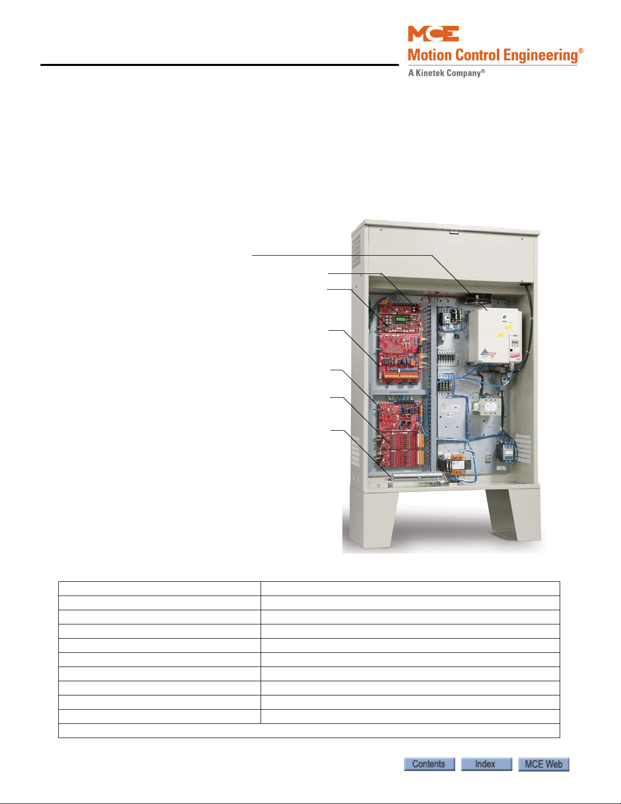
Motion 4000 Traction Elevator Control
AC Drive
CAN Hub & Power distribution
MPU Board
Control Board
Motion Processor Interface Board
Panel Mount Terminals
Universal I/O Boards
Standard cabinet dimensions:
16” x 42” x 72” (406 x 1067 x 1829 mm)
including legs (12” (305 mm).
Motion 4000 Traction Elevator Control Overview
A Motion 4000 controller order may include:
• Controller: Configured according to customer job survey, field programmable.
• Cartop station: Interface between car-mounted equipment and the car controller.
• Serial panel option: Converts car panel analog button data to serial data stream.
• Optional CAN node boards and wiring for serial hall call.
• User Interface: Standard, controller mounted keypad/LCD, optional hand-held keypad/
LCD units to set controller parameters, optional mView PC application.
Table 1.1 Specifications
Maximum car speed 500 fpm, 2.5 m/s
Configuration Simplex, Duplex, Group up to 6 cars
Landings 32 landings, 64 openings maximum
Motor control TorqMax F5, Magnetek HPV AC drives
Landing/Positioning system Encoded magnetic tape or perforated steel tape
Call Registration Serial or Discrete COP, Serial or Discrete Hall Call
Power requirement 208 – 600 VAC, 50/60 Hz, 3-phase
Environment 32 - 104º F, 0 - 40º C; Humidity 95% non-condensing
*Standard enclosure (includes legs) 42” w x 72” h x 16” d (1067 x 1829 x 406 mm) with knock-outs
Available NEMA enclosures NEMA 4, 4X, 12
* Variations available
1-2 Manual # 42-02-2P24
Page 23

Motion 4000
Note
System Features
Motion 4000 design incorporates:
• Solid state implementation of redundancy and proofing requirements, eliminating relays
whenever possible to improve service life and reliability.
• Retention of the simple LCD/keypad programming interface used on earlier MCE programmable controls but with the addition of a hand-held interface (mPAC) that can be
plugged in to any system CAN connector.
• Easy software updates — Internet download through a PC to the hand-held user interface,
MCE SD card, or EEPROM replacement.
• CAN Bus: Circuit boards and major components all communicate through light weight,
serial CAN Bus connections. Communication between major system components (i.e.,
controller to car, controller to hall calls, etc.) uses shielded, twisted-pair cables connected
to pluggable terminals (CAN).
• ASME A17.1/CSA B44 compliant throughout.
• Field connections: Field connections are handled by Universal I/O boards. The boards are
factory set to handle 24V, 48V, 110V, or 120V AC or DC inputs. This allows a single board
design to service all common inputs.
• Positioning: Permanently encoded magnetic tape, or steel tape positioning systems.
• Minimized hoistway peripherals: Motion 4000 design allows slowdown, emergency terminal, and hoistway access limit switches to be eliminated. These switches exist as virtual
switches in system software.
• Serial hall call: Motion 4000 may use serial hall calls for easier field wiring. The riser drop
provides CAN communication and power to the fixtures. (Discrete hall call wiring is supported through Universal I/O boards.)
• Serial car panel option: Discrete signals from car panel buttons may be serialized for easy
connection to the controller via CAN bus through the cartop interface.
• Light weight traveler and hoistway cabling: Serial communication allows low traveler and
hoistway cable conductor counts.
• Optional monitoring capabilities using mView, iMonitor, and iReport software.
• Optional integration with Building Management Software using BMS-LINK.
• Optional Jail Services application for detention center operation.
• (MRL) Optional passenger rescue system provides input from a cartop mounted camera
and a rescue control panel with LCD display to allow a technician to safely drift the car to a
landing in the absence of commercial or emergency power. Once at the landing, doors
must be opened manually.
• Optional Traction Auxiliary Power Supply (TAPS) provides automated return of the car to
a landing and automated door opening in the absence of commercial power. Power is provided via an integrated UPS/battery system and requires no generator.
System Features
1
If the job uses a TAPS system and a TorqMax/KEB F5 drive, drive parameter LF.61 must be set
to Di1.
1-3
Page 24
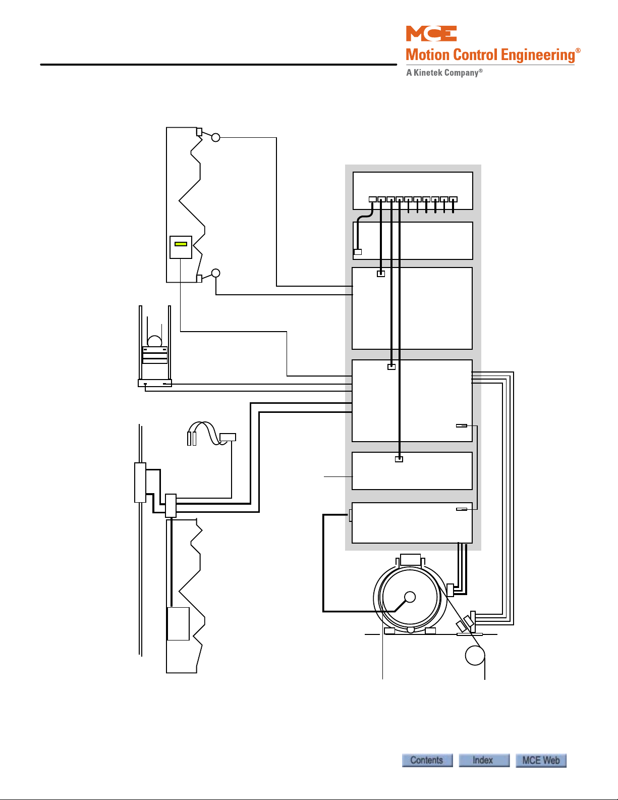
Motion 4000 Traction Elevator Control
r
Figure 1.1 Functional Block
Seismic Sensor
Hoistway
Counterweight
Movement
Detection
Load Weigher
Final Limit
Controller
CAN Hub Board
CAN I/F
Main Processor
Board
Final Limit
Control Board
Motion
Processor
Interface
Board
Encoded Tape
Position Sensors
PS1
PS2
CAN
Cartop I/F
Car
COP
General I/O
Serial I/F
Universal I/O
Board
Drive
Encoder
Rope Grippe
Machine
1-4 Manual # 42-02-2P24
Page 25
Motion 4000
M4000 HC-CHP Board
M4000 HC-MPU Board
M4000 HC-CTL Board
M4000 TC-MPI
M4000 HC-UIO
M4000 HC-UIO
System Component Descriptions
• Controller boards and hand-held user interface
• Car mounted equipment, page 1-6
•Hoistway equipment, page 1-8
Controller Circuit Boards
Circuit boards used depend upon job requirements. Typically, the following boards are used:
• HC-CHP, CAN Hub and Power Supply: Provides
~18-volt, 4-amp DC power for circuit boards in
the controller and a central connection point for
the Controller Area Network (CAN).
• HC-MPU, Main Processing Unit: Fitted with the
appropriate software, performs control data processing. The HC-MPU is responsible for:
•Car operation
•Fire Service
• Programming and diagnostics
• Software validation
• Duplexing / Group communication
• HC-UIO, Universal Input/Output Board: HCUIO boards are used for field inputs and outputs. The boards are universal in that they can
be configured for AC or DC inputs from 24 to
120 Volts.
• TC-MPI, Motion Processor Interface Board:
Configured to interface to the drive selected for
the job. Handles machine and brake contactors,
position system I/O, earthquake/seismic and
emergency brake/rope gripper requirements.
• HC-CTL, Control Board: Monitors I/O, performs
safety functions, front door operation, and
machine room inspection. The HC-CTL board is responsible for:
•Inspection
• Test operation
•Diagnostic Flags
• Front Hall and Car Door Lock Bypass
• Lanterns and Gongs
•Spare I/O
System Component Descriptions
1
Additional circuit boards may be used, including:
• Rear Door board: Second door operator interface board.
• CE Fixture board: Used with external, serially controlled position indicator and annunciator fixtures.
1-5
Page 26
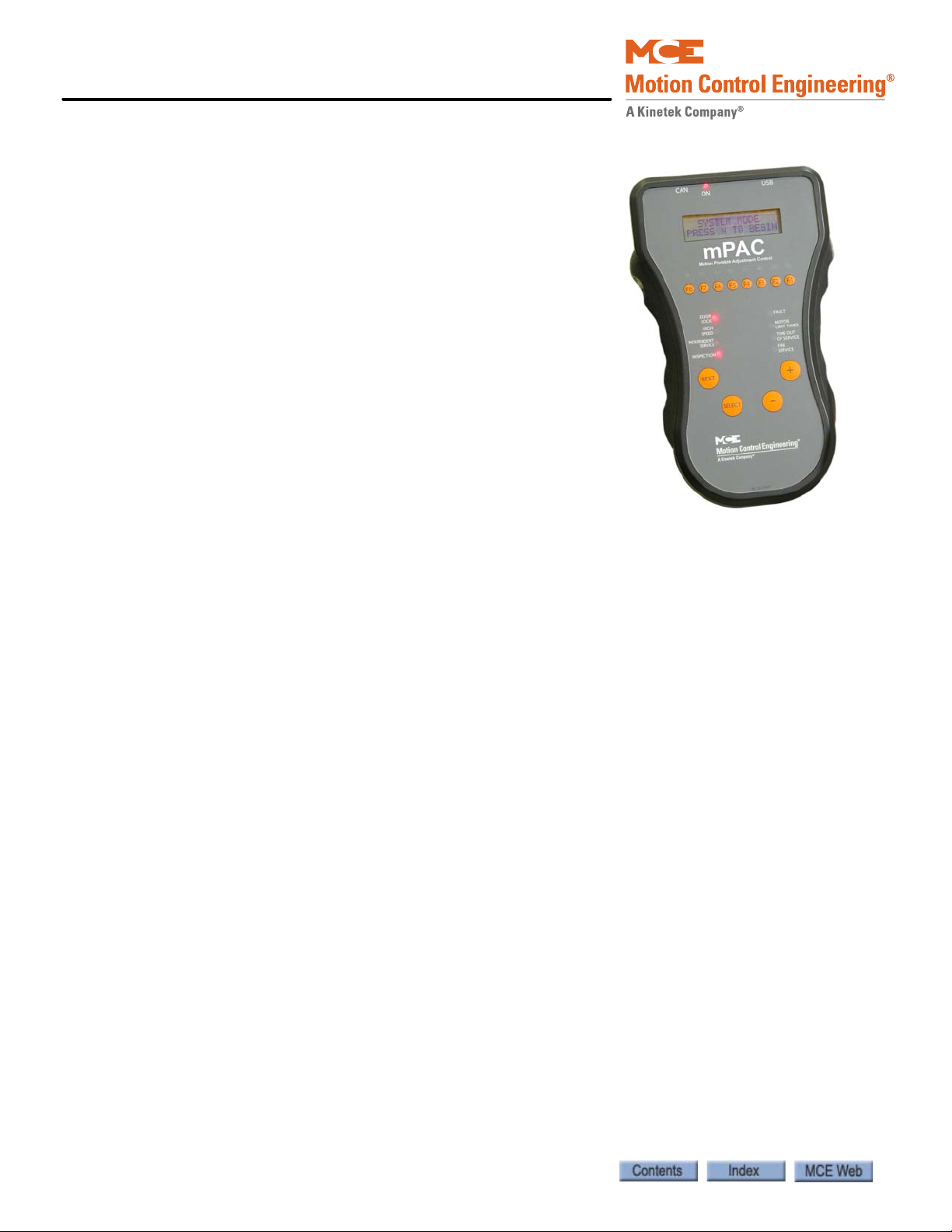
Motion 4000 Traction Elevator Control
Hand-Held User Interface
The hand-held user interface, mPac, provides a portable
interface and a means to upload new firmware to the system.
The hand-held can be plugged in to a CAN connection in the
controller, on the cartop, or in the car (if one is wired).
Car
Landing and Positioning
Motion 4000 uses one of two landing systems; encoded
magnetic tape or perforated steel tape and magnets.
The ELGO encoded steep tape system uses a 1/2-inch wide,
Gray code, magnetically encoded tape and two, independent
sensor heads (in a single housing) for absolute position control under all powered conditions. The tape provides a
unique code for every 1mm of travel. In addition to position,
simple distance-over-time calculation provides extremely
accurate speed feedback. A third, also independent system
provides speed feedback directly from the hoist motor.
The LS-EDGE positioning system uses hall-effect sensors and perforated steel tape to report
position as the car moves through the hoistway. 5.5-inch magnets are used at each door zone;
one row for front openings, a second for rear openings. The system auto-corrects at each door
zone to prevent error accumulation.
The system uses capacitor-stored power and non-volatile memory to retain position information in the event of a power failure, continuing to capture information for 22 seconds after
power loss and storing the final reading for use after power restoration. Mechanical final limit,
ETS, and ETSL switches are used but normal terminal switches may be virtual, existing only in
system software, or mechanical depending upon specific controller capabilities. The LS-EDGE
system may be used with MCE iControl or Motion 4000 elevator controls.
1-6 Manual # 42-02-2P24
Page 27
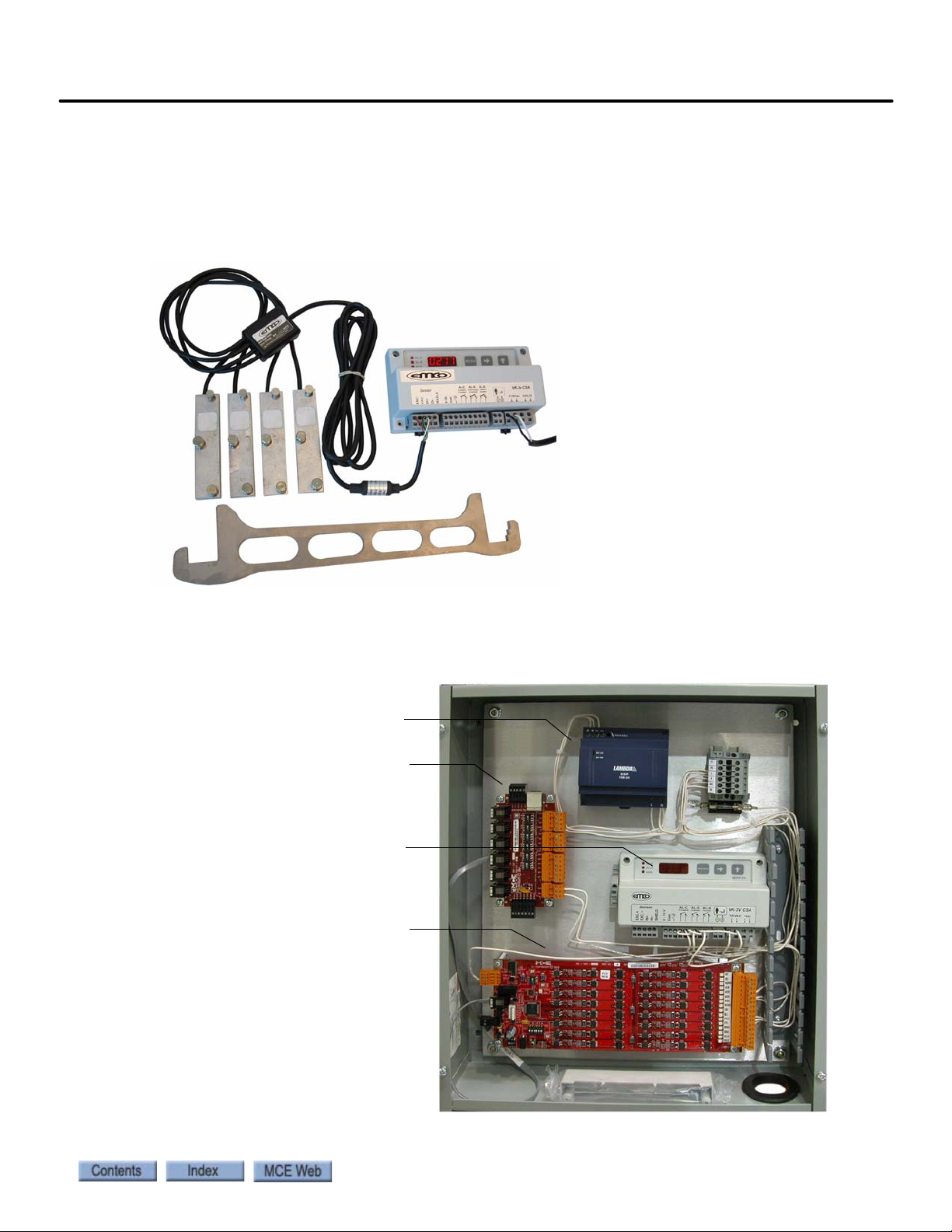
Motion 4000
Sensors (1 per rope)
Processing unit
Installation tool
24V Power Supply
Landing System Interface board
EMCO load weigher control unit
Universal I/O board
Car top box dimensions depend upon
required components. Enclosure shown is
4” x 15” x 18” (102 x 381 x 457 mm).
Minimum enclosure is 4” x 8” x 12”
(102 x 203 x 305 mm).
Load Weigher
Motion 4000 may use an EMCO rope strain gauge for load weighing. The controller uses the
load weigher input to determine overload conditions and also in conjunction with car call registrations and photo-eye information to make anti-nuisance related decisions.
System Component Descriptions
Figure 1.2 EMCO Load Weigher
Cartop Box
A typical Motion 4000 cartop box is pictured below.
Figure 1.3 Motion 4000 Cartop Box
1
1-7
Page 28
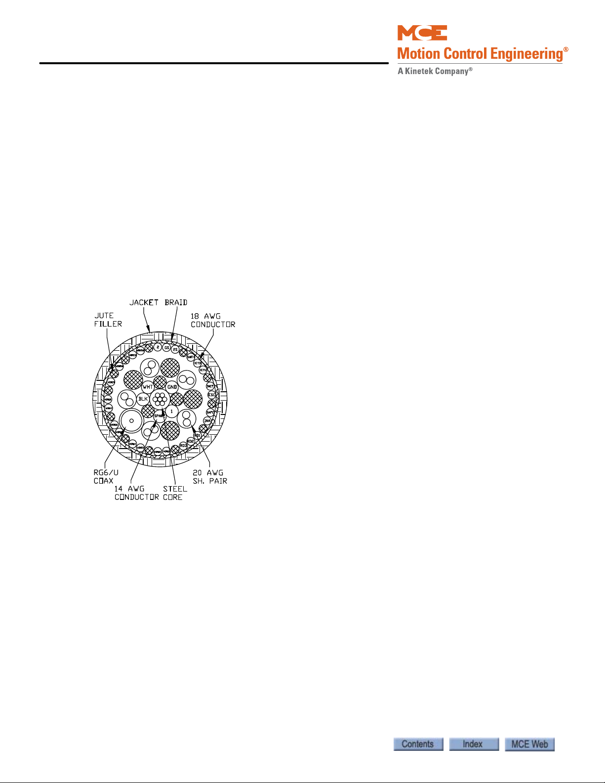
Motion 4000 Traction Elevator Control
Hoistway
For serial hall call, Motion 4000 communicates with hall calls and similar buttons or key
switches through an independent CAN Bus for reliability and easy installation. The hall bus provides a CAN signal path and 24 V power for the fixtures.
An SC-3HN three-input hall node board allows discrete hall call buttons and indicators to be
connected along a CAN bus to provide serial hall call capability for Motion 4000, greatly reducing the number of conductors necessary in hoistway wiring bundles. Please refer to “SC-3HN
Three Input Serial Hall Call Node Board” on page 5-72.
Discrete hall calls are supported using HC-UIO Universal I/O boards. Please refer to “HC-UIO
Universal Input/Output Board” on page 5-58.
Motion 4000 Specific Traveler Cable
Special traveler cable for Motion 4000 installations is available from MCE. The cable is sized
and labeled to make controller to car connections as simple as possible. MCE PN# 44-03-0034.
1-8 Manual # 42-02-2P24
Page 29

Motion 4000
Operating Mode Descriptions
Available operating modes are configured when the car is installed. Not all modes are available
on all cars. This section describes operating modes, including:
•Normal Operation
• Inspection Operation (cartop, in-car, access, machine room)
• Attendant Operation
• Independent Operation
• Sabbath Operation
• Emergency Medical Operation
• Hospital Operation
• Seismic Operation
•Fire Operation
• Emergency Power Operation
•Car Recall
• Capture for Test
•Test Mode
Operating Mode Descriptions
1
Normal Operation
Normal operation is the default elevator operating mode. In this mode, cars are accepting hall
calls and servicing car calls as determined by Basic Features Menu and other operating menu
selections. Please refer to “Basic Features Menu” on page 4-13 . Cars are running at contract
speed as affected by short or multi-floor run performance curves.
Inspection Operation
In inspection, a car operates at the set inspection speed using continuous pressure up and down
buttons or switches. The car will stop as soon as the buttons are released. Inspection operation
may be controlled from four locations. For safety purposes, locations have a priority:
•Cartop
•In-Car
•Access
• Machine Room Inspection
Cartop Inspection
In this mode, the car is operated by pushing the cartop UP or DOWN and ENABLE buttons
simultaneously. These buttons are generally provided through a third-party inspection station
wired to inspection operation inputs in the elevator controller. There will also be a key switch
that enables/disables inspection operation.
Mode Entry
• Bring the car to the access floor
• Enable hoistway access operation using the in-car switch
• Move the car down using the hall controls until the access limit is opened
• Set the cartop switch to Inspection and access the cartop.
• Use ENABLE and UP or DOWN buttons to run the car from the cartop.
1-9
Page 30
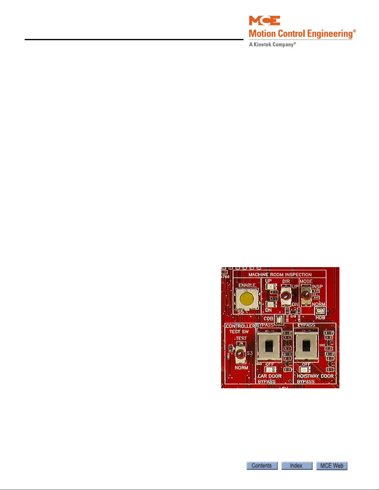
Motion 4000 Traction Elevator Control
In Car Inspection
In this mode, the car is operated using a locked subpanel in the COP that provides the inspection key switch and direction buttons. (Top and bottom car call buttons may be used as direction buttons as well.)
Mode Entry
• Bring the car to the desired floor.
• Place the car on in-car inspection.
• Use UP or DOWN buttons to run the car.
Hoistway Access Inspection
Hoistway access operation allows workers to access the top and bottom of the car from designated floors. In this mode, the car is brought to an access floor where a key switch is used to
move the car up or down.
Mode Entry
• Bring the car to the access floor
• Place the car on hoistway access using the in-car switch.
• Move the car using the hall way switch until the access limit is opened
• Top access must prevent the car from moving down beyond the point where the crosshead is even with the hoistway entrance sill.
• Bottom access must prevent the car from moving up beyond the point where the bottom of the toe guard is even with the hoistway entrance header
Machine Room Inspection
In this mode, the car is operated using switches on the
HC-CTL (Control) board in the controller.
Mode Entry
• Place the car on Machine Room Inspection
(Mode Switch to Inspection).
• Ensure that car and hoistway doors are closed
and locked.
• Run the car using the ENABLE and UP or
DOWN Directional switch positions.
1-10 Manual # 42-02-2P24
Page 31

Motion 4000
Attendant Operation
Attendant operation allows an operator riding in the car to run the car, choosing run direction,
and which hall calls to answer. In this mode:
• Doors open automatically when the car is stopped in a door zone.
• The attendant closes the door by pressing and holding the door close button, a car call button, or either car direction (UP/DOWN) button (UPI/DNI input: Please refer to “Spare
Inputs Menu” on page 4-26.)
• The attendant chooses the direction using run up (UNI) or down (DNI) buttons.
• The car will stop at the next car or hall call in the direction of travel. Holding the bypass
button (NSI input) in will cause hall calls to be bypassed until the button is released. An
annunciator panel is required if in-car visibility of hall calls is required.
• The elevator will level into the destination floor automatically, then open its doors.
• During Attendant operation, load weigher inputs are ignored.
Mode Entry
• Call the car to a floor.
• Enter the car and activate the Att endant mode ke y switch (enabl es the ATS, Atten dant Service, controller input).
Operating Mode Descriptions
1
Independent Service
In this mode:
• The car is removed from hall call dispatching
• Doors open automatically when the car is stopped in a door zone
• The operator presses and holds the door close button to close doors
• The operator chooses direction and initiates the run by placing car calls (first placed determines direction of run).
• The elevator will level into destination floors automatically and open its doors.
• Hall arrival lanterns or jamb mounted arrival lanterns are inoperative.
Mode Entry
• Call the car to a floor.
• Enter the car and activate the Independent mode key switch (IND input HC-CTL board).
1-11
Page 32

Motion 4000 Traction Elevator Control
Sabbath Operation
Sabbath operation is a special mode that sets the car to consecutively service specified landings
(and openings if the car has front and rear doors) during up and down travel with no hall or car
call buttons being pressed. The car will begin from the bottom of the hoistway, travelling up and
stopping at each designated stop and opening its doors to allow exit or entry. When the doors
close, the car will travel to the next designated stop up the hoistway and repeat door operation.
This will continue until the car reaches the top designated stop, at which point it will travel
down the hoistway operating in the same manner.
• Initiate: Sabbath operation is initiated when the spare input SAB is activated.
• Operation: In accordance with the description above and servicing stops set through the
Sabbath Operation parameter in the Extra Features menu. Please refer to “Extra Features
Menu Options” on page 4-42.
Emergency Medical Operation
This mode complies to Massachusetts code. It allows a car to be recalled to a floor where it can
be boarded by medical personnel and placed in restricted service, using an in-car switch, to
respond to a medical emergency.
• Recall: Initiated using a key switch (EMSH input) at the floor assigned by the Massachusetts EMS Service/EMS Service Floor parameter in the Extra Features menu (single
switch, single floor).
• The car will immediately cancel all registered calls, return to the designated floor, and
open its doors.
• In-Car Medical: Medical personnel board the car and place it in hospital service using the
in-car switch (EMSC input).
• If the hall switch has been shut off, the car will wait sixty seconds then return to normal service if the in-car switch has not been activated.
• If the hall switch remains on, the car will wait without restriction until the in-car
switch is activated.
1-12 Manual # 42-02-2P24
Page 33

Motion 4000
Note
Hospital Service
Please refer to “HOSPITAL EMERG. OPERATION?” on page 4-45. Hospital service allows a car
to be recalled to any of one or more assigned floors using a call button at the floor. Once at the
floor, the car may be boarded by medical personnel and placed in restricted service, using an incar switch, to respond to a medical emergency.
• Recall: Floors and openings (if the car has front and rear doors) are designated as hospital
service through Hospital Emerg Operation parameters in the Extra Features Menu. Please
refer to “Extra Features Menu Options” on page 4-42. When a designated call button is
activated, the car will recall to the floor.
• The car will immediately cancel all registered calls, move to the call floor, and open its
doors.
• A Timer Menu function, Hospital Emergency Timer, allows a timer to be set for a
range of up to 10 minutes. After a car recalls to the designated floor, it will remain
there until the timer expires, after which it will return itself to automatic passenger
service if the in-car, hospital service switch has not been activated.
• Operation: Once the in-car switch (HOSP input assigned through the Spare Inputs Menu)
is activated, the car is in restricted service and will accept only calls assigned through the
car operating panel.
• When the in-car switch is deactivated, the car returns to normal service.
Operating Mode Descriptions
1
Seismic Operation
Please refer to “EARTHQUAKE OPERATION?” on page 4-48. Seismic operation is entered into
automatically if counterweight derailment is detected (CWI input) or if the seismic sensor input
(SSI) is activated. If the CWI input is triggered, the car comes to a full stop, moves at reduced
speed (150 FPM or less) to the nearest floor in the direction away from the counterweight, levels, opens its doors to allow passengers to exit, then shuts down.
If only the SSI input is activated, the car will continue to the next available floor, open its doors,
and shut down. A programmable option is available to allow the car to run on normal, automatic operation or fire service at reduced speed (150FPM or less).
Mode Exit
• After ensuring that the hoistway is clear and all equipment is undamaged and operating
properly:
• Press the EQ Reset button on the Motion Processor Interface (MPI) board.
Modifiers
Some fire codes allow the car to be run in fireman service even though the CWI or SSI input has
been activated.
Earthquake operating profile overrides the Emergency power profile.
1-13
Page 34

Motion 4000 Traction Elevator Control
Fire Service Operation
There are many different fire codes that restrict or change elevator operation under fire conditions. Please refer to “Fire Service Menu Options” on page 4-16. In general, fire service proceeds
in two stages; Phase I Fire Recall and Phase II Fire In-Car Operation. When a fire sensor or
switch is activated:
• The elevator will recall to the designated main or alternate recall floor. (Main if fire
detected on any floor other than the main floor; Alternate if fire detected on the main
recall floor. Or, as directed by a manually activated Fire switch.)
• The elevator will open its doors to allow any passengers to exit, then remain at the recall
floor until the in-car firefighter switch is activated. Once the in-car switch is activated the
car will run on Fire Phase II operation as allowed by the selected fire code.
Emergency Power Operation
Please refer to “EMERGENCY POWER OPERATION?/EMERGENCY POWER RETURN
FLOOR” on page 4-42. Emergency or standby power operation requires a backup power source.
For large buildings, this is typically a diesel or gasoline powered generator. When this is not
practical, backup power for a limited, rescue operation may be provided by a battery-powered
system like the MCE TAPS (Traction Auxiliary Power Supply).
Generator Backup
When power is lost, the elevator will come to a full stop. When emergency/backup power comes
on line, the elevator will be moved at programmed speed to a designated recall floor and the
doors will open to allow passengers to exit. The elevator will remain at the recall floor unless it
is designated to run under generator power.
TAPS Backup
When power is lost, the elevator will come to a full stop. When battery power becomes available,
the elevator will be moved at reduced speed to the nearest floor in the direction determined by
TAPS settings. At the floor, the doors will cycle, allowing passengers to exit, and then close. The
car will remain out of service until commercial power is again available and the TAPS unit
switches the car from battery power back to normal power. Please refer to the MCE TAPS manual or data sheets for detailed information.
1-14 Manual # 42-02-2P24
Page 35

Motion 4000
Note
Car Recall
Inputs may be provided to allow the car to be recalled to a specified floor.
• CTF: Car To Floor - This is a “sp are” inp ut that may be assigned to the HC-CTL board or to
a Universal I/O board as configured for the job. The floor to which the car is returned is set
by the Car to Floor Return Floor parameter in the Extra Features menu. Please refer to
“Extra Features Menu Options” on page 4-42.
• When activated, causes the car to stop responding to hall calls. Existing car calls will be
• At the return floor, the car will open then close its doors and remove itself from service.
• CTL: Car to Lobby - This is a “spare” input that may be assigned to the HC-CTL board or to
a Universal I/O board as configured for the job. The floor to which the car is returned is set
using the Lobby Floor parameter in the Basic Features menu. Please refer to “Basic Fea-
tures Menu” on page 4-13.
• When activated, causes the car to stop responding to hall calls. Existing car calls will be
• At the lobby floor, the car will open then close its doors and remove itself from service.
Operating Mode Descriptions
1
serviced before or after recall depending on the setting of Retain Calls (see note
below). New car calls will not be registered.
serviced before or after recall depending on the setting of Retain Calls (see note
below). New car calls will not be registered
RETAIN CALLS?: There is a function in the Extra Features menu that determines if registered
car calls are serviced before or after recall. Please refer to “RETAIN CALLS ON CTL / CTF?” on
page 4-48.
Capture for Test
CTST: Capture for Test - This is a “spare” input that may be assigned to the HC-CTL board or to
a Universal I/O board as configured for the job.
• When this input is activated, the car will stop responding to hall calls and disable its gongs
but continue to service car calls.
• The intent of the input is to allow maintenance personnel to capture the car while causing
as little disruption to service as possible.
Test Mode
Test mode allows the car to be run on automatic operation without operating the doors. When
Test mode is active, door opening circuitry is deactivated and hall calls will not be registered.
• Enter Test mode by placing the TEST/NORMAL switch on the HC-CTL board in the TEST
position. (The car will not enter Test mode if Inspection is active.)
• When Test mode is active, the controller LCD will display TEST MODE.
1-15
Page 36

Motion 4000 Traction Elevator Control
Monitoring and Control Options
Motion 4000 is Ethernet capable, allowing it to use iMonitor and iReport applica t ions fo r loca l
and/or distance monitoring and control or report generation, archival, and automated alert.
Motion 4000 can be linked to Building Management System software through MCE BMS-Link,
providing system visibility and limited control. A machine room-only monitoring and control
application, mView, is also available.
iMonitor
iMonitor is an elevator monitoring application that allows local or remote viewing and control
of MCE elevator groups using a personal computer running the Windows XP or Windows 7
operating system. Because Motion 4000 controls are Ethernet capable, you can connect to them
though a local area network or remotely through internet technology.
iMonitor provides a graphical representation of elevator groups, allowing their activity and status to be quickly and easily viewed. The user defines any number of “Connection Sets.” Each
Connection Set consists of up to fifty connections to elevator group dispatchers selected by the
user.
When working in iMonitor, the user simply clicks on a Connection Set which automatically
establishes communication with all groups in the set and displays their associated hoistways
and cars on the computer screen. Practical viewing limits are established by the speed of the
connections and the size of the monitor viewing area.
When connected through iMonitor, the user may register car and general, auxiliary, or special
hall calls as desired, control many group security functions, and enable or disable certain elevator operating modes.
iReport
iReport is a system logging and report generating tool that allows local or remote analysis of
MCE elevator groups from a personal computer running the Windows XP or Windows 7 operating system and iReport client software. Because Motion 4000 controls are Ethernet capable,
you can use iReport to connect to them through a local area network or remotely through internet/modem technology.
iReport consists of the iReport server and iReport clients. Motion 4000 group dispatchers may
be connected to iReport directly through a local area network or they may be connected
remotely through the internet. The group dispatcher provides iReport with hall call and car
operating mode information. The individual car controllers provide iReport with event and
fault notifications.
1-16 Manual # 42-02-2P24
Page 37
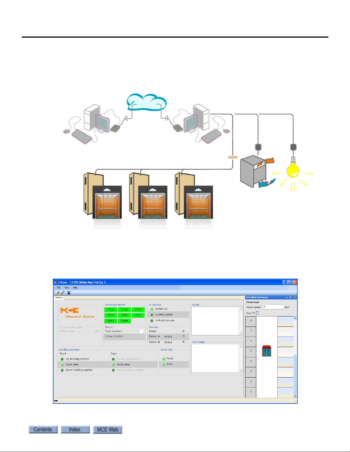
Motion 4000
Internet
Utility Company
Building Automation
Heating/Cooling Plant Lighting
Intelligence Intelligence
BMS-LINK
Elevator Controllers
BMS-Link
BMS-LINK allows MCE elevators and escalators to be viewed and monitored using Building
Management Software. Control capabilities in keeping with management system software
needs are provided.
Monitoring and Control Options
1
mView
The mView application runs on a standard PC connected to the controller through an Ethernet
hub or switch. mView provides local monitoring, status and event log viewing, diagnostics, and
call registration for one or more Motion 4000 controllers.
1-17
Page 38

Motion 4000 Traction Elevator Control
1-18 Manual # 42-02-2P24
Page 39

In this Section
This section contains instructions for installing the controller and peripheral equipment. If you
are reading this on a computer, click the blue text to jump to the appropriate section.
• Safety: page 2-2.
• Preparation: page 2-3.
•MCE Wiring Prints: page2-5.
• Controller Installation: page 2-6.
• Connect AC power: page 2-10.
• Connect motor, brake, encoder: page 2-11.
•Emergency Brake/Rope Gripper installation: page 2-14.
• Initial Power Up: page 2-14.
• Auto-Tune Drive: page 2-17.
• Set up for Construction operation: page 2-28.
• Set up for Inspection operation: page 2-51.
• Running on Inspection: page 2-54.
• Finishing Installation: page 2-55.
• Installing the landing system: page 2-56.
• Adjust Brake: page 2-83.
• Traction Auxiliary Power Supply: page 2-84.
• Installation Review: page 2-84.
Installation
2-1
Page 40

Installation
The job prints are the primary document used to install the controller. The job prints and manual together provide information to install, adjust, and troubleshoot the controller. Study the
job prints and read the manual before starting work. Call MCE with any questions.
Instructions in this section assume that the hoist ropes are attached to the car sling, all hoistway
doors are closed, and that:
• The CAR SAFETY IS ADJUSTED to the manufacturer specification
• The GOVERNOR IS INSTALLED and the GOVERNOR ROPE CONNECTED to the safety
Safety
Certain fundamental warnings must be kept in mind at all times to help avoid accidental death,
severe personal injury, or equipment damage.
Personal Safety
• Motion 4000 Controllers may only be installed by qualified, licensed, trained elevator personnel familiar with the operation of microprocessor-based elevator controls.
• Verify safety devices (limits, governors, hoistway locks, car gate, etc.) are fully functional
before running the elevator. Never operate controls with any safety device inoperative.
• The user is responsible for complying with the current National Electrical Code with
respect to the overall installation of equipment and proper sizing of electrical conductors.
• The user is responsible for understanding and applying all current local, state, provincial,
and federal codes that govern practices such as controller placement, applicability, wiring
protection, disconnections, over-current protection, and grounding procedures.
• Controller equipment is at line voltage when AC power is connected. Never operate controls with covers removed from drive or brake controls.
• After AC power has been removed, internal capacitors can remain charged for up to 5 minutes. Wait at least 5 minutes after power down before touching any internal components.
• To reduce the risk of shock, all equipment should be securely grounded to earth ground.
Failure to obtain an actual earth ground may result in electrical shock to personnel. Pro-
vide equipment grounding in accordance with local code and NEC Article 250.
• When using test equipment (oscilloscopes, etc.) with a power cord that electrically ties
probe common to earth ground, an isolation transformer should be used to isolate the
instrument common from earth ground.
• Remain clear of all rotating equipment while working on the controls.
2-2 Manual # 42-02-2P24
Page 41

Motion 4000
Equipment Safety
• Provide equipment grounding in accordance with local code and NEC Article 250. Failure
to obtain a true earth ground may result in electrical shock. Improper grounding is the
most common cause of electrical component failure and noise-induced problems.
• Replace components only with main line power off. Damage to equipment or unexpected
operation of the elevator may occur if this precaution is not observed.
• Do not substitute or modify parts. MCE will not be responsible for modifications made in
the field unless they are approved in writing by MCE.
• Circuit boards believed to be defective must be sent to MCE for repair and testing. Field
repair may leave the board with undetected problems.
• Care should be taken when using test leads and jumpers to avoid shorting high voltage or
ground to low voltage microprocessor circuits.
• Do not allow dust, carbon, or metallic particles to accumulate on any part of the control.
• Avoid vibration, shock, high humidity, high ambient temperature, and caustic fumes.
Preparation
When choosing equipment location, consider:
Preparation
2
• Logical arrangement, taking into consideration other equipment, electrical power, and
seismic zone requirements.
• Do not install equipment in hazardous or vibration prone locations.
• Locate the drive isolation transformer (if used) near the controller to reduce wire runs.
• Ambient temperature should remain within 32
Temperatures outside these guidelines may be tolerated, but will shorten equipment life.
Adequate ventilation is required. Air conditioning may be necessary.
• The air in the machine room should be free of excessive dust, moisture, or corrosive elements. A NEMA 4 or NEMA 12 enclosure can help meet these requirements if machine
room conditions are inadequate. If the machine room has open or unglazed windows or
other direct outside openings, place equipment cabinets far enough from them that severe
weather does not damage the equipment.
• Very high levels of radio frequency (RF) radiation from nearby sources should be avoided.
RFI may interfere with controller components, degrading elevator performance. Using
hand-held communication devices close to the controller may also cause interference.
Interference from permanently installed radio transmitting antennas is not common.
• Power line fluctuation should not be greater than ±10%.
° to 104° Fahrenheit (0° to 40° Celsius).
2-3
Page 42

Installation
Electrical Noise
Electrical noise readily occurs when two wires run along side one another with one of them a
high power conductor and the other a low signal level conductor. The easiest way to avoid noise
problems is to keep low-level wiring in separate conduit from high power wiring. If high and
low power wiring must be run in the same duct, separate them by a minimum of three to four
inches. If one must cross the other, it should be at a ninety degree angle.
Alternately, low level wiring may use shielded cable. The shield drains induced voltage to
ground. The shield must be connected to ground at one end only.
EMI/RFI
To avoid EMI/RFI interference:
• Keep motor leads as short as possible. Run them in a separate conduit.
• Run main line supply leads to the controller or isolation transformer in a separate conduit.
• Run leads from the isolation transformer to the drive cabinet in a separate conduit.
• The controller door will protect against interference only when closed.
Recommended Tools and Test Equipment
Recommended tools and test equipment:
• Digital multimeter, Fluke series 75, 76, 77 or equivalent
• Hand-held tachometer
• Clamp-on AC ammeter
• Hand-held radios
•Test weights
2-4 Manual # 42-02-2P24
Page 43

Motion 4000
Car Number
Page Number
Job Number
Yea r
MCE Wiring Prints
Become familiar with the wiring prints provided with your control system.
Drawing Number Format
Each print has a drawing number. The drawing number is comprised of the job number, car
number, and page number (see example).
Nomenclature
The following table lists board name and part numbers. Your installation may not use all boards
listed.
MCE Wiring Prints
2
Table 2.1 Component Nomenclature
Board Name Description
HC-DB-MOD Front G. A. L. MOD Door Interface Board
HC-DB-MOD-R Rear G. A. L. MOD Door Interface Board
HC-CTL Controller Board
HC-RDR Rear Door Board
TC-MPI Motion Processor Interface to drive
HC-UIO Universal I/O Board
HC-CHP CAN Hub and Power Board
HC-MPU Main Processor Board
ICE-COP-2 Control panel interface board
MC-CPI Control panel interface board
MC-LSI Landing System Interface Board
SC-3HN Three Input Hall Call Node Board
Power Nomenclature
MCE job prints and power terminals within the controller are numbered to identify different
power buses:
• 1: The number 1 (one) bus is system Common.
• 2: The number 2 (two) bus is AC power.
2-5
Page 44
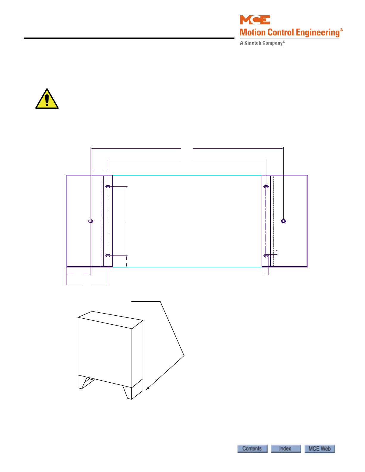
Installation
Caution
27.50
33.50
3.00
7.25
4.25
12.00
2.00
0.75
0.44
Dimensions for attaching base feet of Standard NEMA 1 enclosure (16” deep x 42” wide)
to floor.
Controller Installation
Mount the controller securely to the machine room floor and use provided wiring knock-outs to
install raceway or conduit to route wires into the cabinet.
If you drill or cut the cabinet, do not allow metal chips or shavings to fall into electronics.
Damage caused by this is not covered by warranty.
Figure 2.1 Mounting Template for Standard NEMA 1 Cabinet with Feet
2-6 Manual # 42-02-2P24
Page 45
Motion 4000
Note
Caution
Danger
Controller Wiring Guidelines
Detailed instructions for connecting the Motion 4000 controller and accompanying components are contained in the drawings package for the job. During the job survey, site-specific
information collected is used to engineer the drawings package. Contact Motion Control Engineering immediately if you have questions about the drawings or need additional assistance.
Be aware of the hierarchy of the inspection inputs. (Cartop has highest priority. In-car is next.
Machine Room is last.) In order to maintain safe operation of the lift while on access, car top, or
in-car inspection, the inspection circuits must be wired as shown in the prints.
PC boards can be easily damaged by Electrostatic Discharge (ESD). Use a properly
grounded wrist strap when touching PC boards. Do not touch PC Boards unless you are
properly grounded.
Controller Installation
2
• Use the wiring ducts in the controller. The terminals are located conveniently near them.
• Connect wires according to hoistway and car wiring diagrams.
• If the car is part of a duplex or group, there are additional steps related to wiring interconnects between individual cars:
• A separate conduit or wiring trough must be provided for the CAN link between each
controller cabinet.
• Wiring details are shown in the job prints.
• Ground all cabinets according to applicable guidelines. Please refer to “Proper
Ground” on page 2-7.
Proper Ground
Provide equipment grounding in accordance with local code and NEC Article 250. A proper
ground is essential to trouble free operation. Ground is defined as a direct connection to
EARTH GROUND. This type of ground is not always available in the electrical supply panel.
Electrical conduit is not a sufficient ground. Electrical ground should be obtained and certified
by the electrical contractor. When seeking an adequate EARTH GROUND:
• Consult with the building engineer or electrical contractor to determine the best source for
a low impedance ground.
• Sprinkler system water pipe is not adequate because the sprinkler system is, in most cases,
isolated from a free flowing earth water source.
If a poor ground connection is used and a true electrical ground is later introduced into the
system, the difference in potential can lead to the possibility of severe electrical shock to
personnel and damage to test equipment.
2-7
Page 46
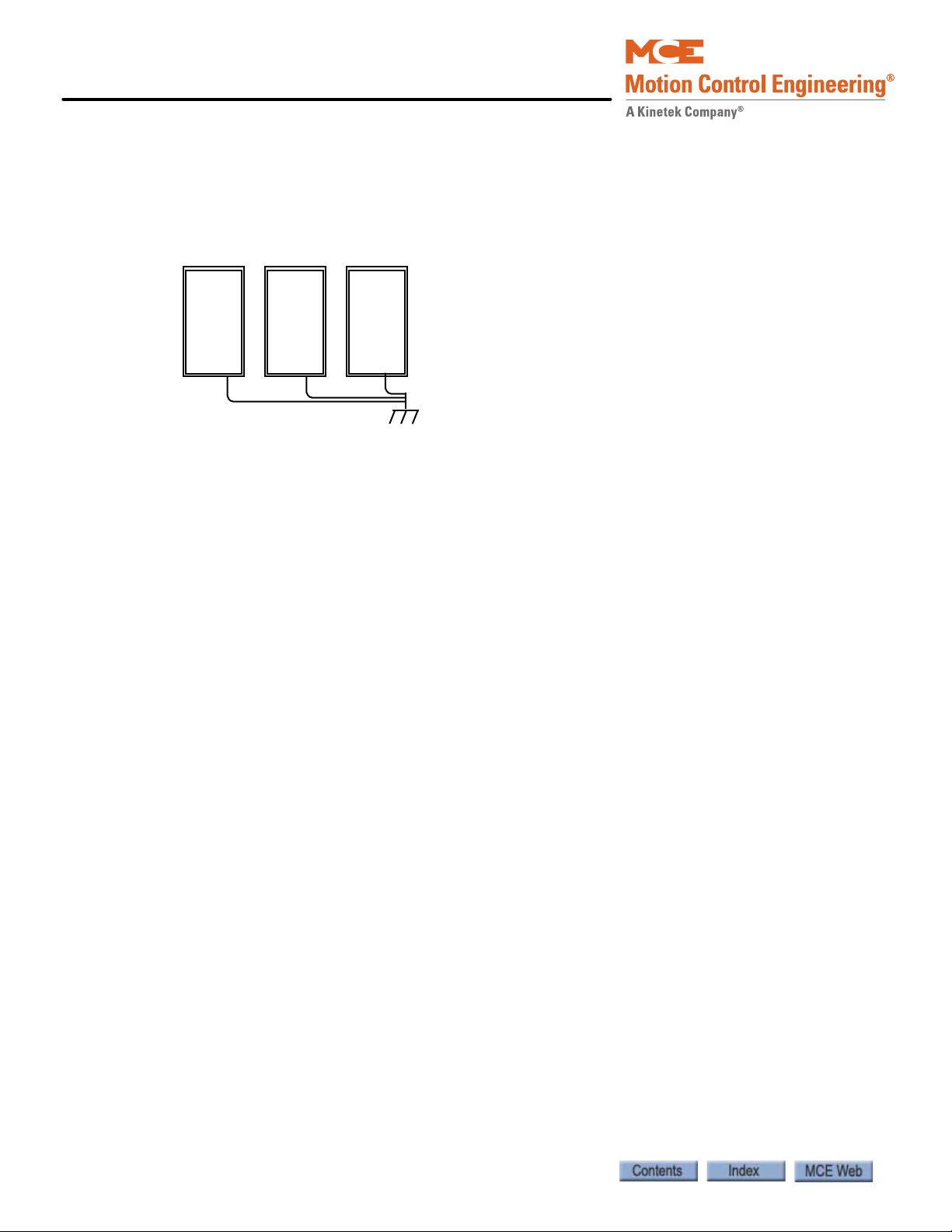
Installation
• The chosen ground must conform to all applicable codes. Proper grounding is essential for
system safety and helps to reduce noise-induced problems.
• Direct, solid grounding must be provided in the machine room to properly ground the controller and the motor.
Figure 2.2 Ground Wiring to Controller Cabinet
1. An uninterrupted ground wire should be run from each car controller cabinet chassis or
back plate to earth ground. The connection at the car controller must be free of paint so
connection is made to bare metal. There should be less than 1-ohm to ground with the
power off.
2. Ground straps, or short loops of ground wire, should be run from the controller ground connection to the primary duct connections.
3. An uninterrupted ground wire should be run from the hoist motor frame to the controller ground. The ground connection to the hoist motor must be free of paint.
4. An uninterrupted ground wire should be run from a termination point on the cab to the controller ground.
5. An uninterrupted ground wire should be run from the cab enclosure to the ground terminal on the cab to protect passengers from electrical shock.
6. An uninterrupted ground wire should be run from each car operating panel to the ground terminal on the cab to protect passengers from electrical shock.
7. An uninterrupted ground wire should be run from the dispatch cabinet chassis or back plate to earth ground. The connection must be to the bare metal of the enclosure.
2-8 Manual # 42-02-2P24
Page 47
Motion 4000
Danger
Check for Shorts to Ground
Check for shorts to ground before powering up the system. Power must be OFF at the main
disconnect. If any shorts to ground are discovered, they must be corrected before proceeding.
A short to ground is defined as having a resistance of less than 20 ohms between ground and the
terminal being tested.
Be certain that power is OFF at the main disconnect before proceeding.
1. Disengage all 2 Bus fuses.
2. Measure the resistance between the 1 Bus (common) and all field connection terminals.
3. Check for shorts to ground on motor power terminals L1, L2, and L3.
4. Check for shorts to ground on brake terminals B1 and B2, EB1, and EB2 (as applicable).
5. If no shorts to ground are discovered, re-engage the fuses.
Controller Installation
2
2-9
Page 48

Installation
Note
AC Power Connections
• All conductors entering or leaving the controller must be through conduit.
• High voltage, high current conductors must be separated from control wires.
• Velocity encoder or tachometer wires must be routed in a separate conduit from high voltage, high current wires.
• Incoming power to the controller and outgoing power to the motor must be through separate, grounded conduits.
Brake Module If your job uses a brake control module, your job drawings may show auxiliary power connections specific to the brake from an isolation transformer. Follow the drawings carefully.
1. Check the AC input specifications on your job prints. Verify that the AC supply is as specified.
Proper motor branch circuit protection in the form of a fused disconnect switch or circuit
breaker must be provided for each elevator according to applicable electrical code. Refer to the
drive manufacturer manual for proper drive circuit fuse sizing. Each disconnect or breaker
must be clearly labeled with the elevator number. The electrical contractor must determine the
wire size for the main AC power supply and for the wiring from the disconnect or breaker to the
controller or isolation transformer.
2. Connect AC supply wiring as shown in the job prints.
Power Check
After connecting power, it is a good practice to temporarily power up the control to check functionality before connecting any field wiring.
1. Verify that the Inspection switch on the Control Board is in the Inspection position.
2. Visually check for loose connections or components.
3. Verify that fuses FB1 and FB2 are disengaged to prevent the brake from lifting.
4. Have a helper power up the controller and remain by the disconnect ready to shut down immediately if needed.
5. Check that the Power On LED on the CHP (CAN Hub) board is on.
• Verify all transformer and power supply voltage levels are correct per the job prints.
• Verify all fuses are intact.
• Check phase-to-phase input voltage. If necessary, shut off main power and swap two of
the incoming feeds at the controller main terminal.
6. After verification, shut down the controller and engage fuses FB1 and FB2 before continuing with field connections.
2-10 Manual # 42-02-2P24
Page 49

Motion 4000
Danger
Caution
Motor, Brake, and Encoder Connection
Motor, Brake, and Encoder Connection
Verify that power to the controller has been shut off at the main disconnect before proceeding with connections.
Motor Connection
If you are reusing an existing hoist motor, you must check it for insulation breakdown
before proceeding. Applying power from a modern drive to a motor with insulation problems can damage the motor and/or the drive.
Insulation Breakdown Test
1. Disconnect all motor and brake wiring.
2. Perform an insulation test between motor and brake connection points and the body of the motor. Use a Megohm meter to subject the insulation to the same high voltage that would be present during elevator operation.
3. A minimum insulation resistance of 100k Ohms is required.
4. Correct any insulation problems before proceeding with installation. Insulation problems may indicate a serious problem in the equipment.
Motor Wiring
Incoming power to the controller and outgoing power wires to the motor must be through separate grounded conduits.
2
1. Refer to the power section drawing in your job prints.
2. Use a shielded power cable between the motor drive and the AC Motor stator connections to reduce RFI/EMI noise (Siemens Protoflex - EMV or equivalent). The shield
must be terminated to earth ground at both ends.
3. Make connections as shown. Be sure to follow any notes regarding wire sizes.
4. Pay particular attention to motor grounding instructions in the job prints and in the motor manufacturer instructions.
MRL or Extended Motor Cables
If cables from the drive to the motor are over forty feet / 12 meters in length, high voltage peaks
or high rates of voltage rise can occur on the motor windings, potentially damaging the motor.
In these installations, a special output filter may be recommended by the drive manufacturer.
Both cable length limitations and filter configuration are dependent on the drive. Refer to the
drive manufacturer manual for specific information and treatment.
2-11
Page 50

Installation
Note
Brake Connection
Motion 4000 controllers may be ordered with or without a brake control module. The module
allows more precise control of brake lift and drop rates. Th e brake module must be calibrated
before it will pick the brake. Please refer to “Calibration (CAN Only)” on page 5-85.
Standard Brake
1. Refer to the brake circuit drawing in your job prints to verify the configuration of the braking circuit. (Brake control and brake adjustment resistors vary from job to job.)
• Familiarize yourself with the brake pick, hold, and drop time adjustments.
2. Measure the resistance through the brake coil on the lift machine.
3. Initially, adjust resistance across the Brake Drop Time resistor(s) to three times the measured brake coil resistance.
This resistance determines brake drop time. Too little resistance causes the brake to remain
picked for a longer time, perhaps allowing rollback before stopping the car. Three times brake
coil resistance is usually a good starting point.
4. Connect the wires from the controller to the brake as shown in the job prints. Remember that brake wires must not be routed in the same conduit with motor power or velocity encoder wires.
Brake Module
If the job uses one machine brake as the service brake and the second machine brake as an
emergency brake, a brake module may be necessary for each depending upon the jurisdiction of
the installation site.
• Connect the wires from the controller to the brake as shown in the job prints. Remember
that brake wires must not be routed in the same conduit with motor power or velocity
encoder wires.
Brake modules must be calibrated to the brake that they will be controlling. Please
refer to “Calibration (CAN Only)” on page 5-87. Both calibration and adjustment
are described in the referenced area of the manual.
Brake Mechanics
Check basic brake characteristics at this time:
• Ensure that the brake mechanism is clean and in good condition.
• Check that the brake lining makes good contact with the machine braking surface (at least
95% of the pad must be in contact with the braking surface).
• Check that the adjustment of the brake solenoid is not preventing the brake from fully
applying when it is not energized.
• Check to see that the spring adjustments are equal and are torqued to the manufacturer
recommended brake torque settings.
2-12 Manual # 42-02-2P24
Page 51

Motion 4000
Note
Caution
Caution
Motor, Brake, and Encoder Connection
Velocity Encoder Installation and Wiring
The velocity encoder reports hoist motor speed to the controller. The encoder must be mounted
and wired according to the drawings. When installed, the encoder must be electrically isolated
from the motor or any other ground. (Resistance between the encoder casing and the motor or
other ground should be “infinite.”)
Do not place the encoder or its wiring close to a magnetic field (the motor or brake coils). Magnetic fields can induce AC into the encoder signal. This can cause the drive to miscount, producing erratic control at lower speeds.
The encoder wiring must use a separate grounded conduit. Inside the controller cabinet, if control wires must cross power wires, they must cross at right angles to reduce the possibility of
interference. We recommend you use oversize conduit (typically 2- inch) so that connectors
may be fed through without having to disassemble the cable.
Encoder Wiring
2
Check job prints and installed encoder type to be certain they match. ONLY
WHEN the drive is switched off and the voltage supply is disconnected may the
feedback (encoder) connections be removed or connected.
A shielded cable with an appropriate connector at the encoder end is connected to the drive if
the type of encoder is known before the job is shipped. If the encoder type is unknown, the cable
ends expose trimmed and tinned individual conductors and the installer must attach the
encoder connector and make the proper connections at the drive end. The encoder cable must
be routed into the controller cabinet in a separate conduit from brake or power conductors.
1. Route the cable through a separate conduit to the controller cabinet.
2. If it was not done at the factory, connect the controller end of the cable as shown on the drive interface sheet of the job prints and according to the encoder manufacturer instructions.
3. Connect the encoder end of the cable to the encoder. (If you are providing the connector, follow the encoder manufacturer instructions.)
Do not coil excess Encoder cable near high voltage components — noise may be induced. If
the cable must be shortened, trim it at the drive end. Do not cut and re-splice in the middle
of the cable or shorten at the Encoder end.
2-13
Page 52

Installation
Note
Danger
Caution
Emergency Brake Installation
Depending upon job configuration, a rope gripper, a sheave brake, or one of the two machine
brakes may be used for emergency braking (unintended motion prevention).
1. Refer to your job prints.
2. Connect the rope gripper or sheave brake as shown.
If you do not yet have the rope gripper or sheave brake on site, refer to Construction Mode
Jumper Requirements on page 2-28.
Resetting the Rope Gripper
During setup, the rope gripper or sheave brake may well be triggered. To reset the unit:
1. Place the car on Machine Room Inspection.
2. Press and hold the Emergency Brake reset button, EB RST, on the TC-MPI board for eight seconds, then release.
3. Return to normal operation. Check the fault display and correct faults as necessary.
Initial Power Up
Always have a helper standing by the AC disconnect to power up the controller and to
immediately shut down if necessary.
1. Verify brake and motor wiring is correct.
2. On the HC-CTL board, verify that the Machine Room Inspection switch is in the INSP position.
3. Physically verify that all car and hoistway doors are closed and locked and that no one is in a dangerous position should the car move unexpectedly.
4. Power up the control. Be prepared to immediately shut it down if the car slides or attempts to move.
5. Check that the drive is displaying no fault conditions.
Turning the control on and off repeatedly (more than once every two minutes) can damage
the inverter drive.
2-14 Manual # 42-02-2P24
Page 53

Motion 4000
Note
Often Used Procedures
Following are some procedures and techniques that are often used while setting up drive and
controller parameters:
How to check Car Speed:
1. Place Function Switch F3 on the HC-MPU board in the ON (up) position.
2. Press the N push button until CONTROLLER SYSTEM MENU is displayed.
3. Press the S push button to select the menu.
4. Press the N push button until POSTN and SPEED are displayed.
5. Run the car. Speed is displa yed in feet per minute.
How to place the car on Inspection Mode Fault Bypass:
1. On the HC-MPU board, place Function Switch F3 in the ON (up) position.
2. On the HC-CTL board, use a jumper to short the pins of JP1 Fault Bypass.
3. Press the N push button until CONTROLLER SYSTEM MENU is displayed.
4. Press the S push button to select the menu.
5. Press the N push button until INSPECTION MODE FAULT BYPASS is scrolled on the display.
6. Press the S push button to change the setting to BYPASS ON.
Initial Power Up
2
Inspection mode fault bypass remains activated, even across power cycles, until switched off.
In the F3 menu, Automatic Mode Fault bypass is just before Inspection Mode Fault bypass.
When you want Inspection Mode bypass, be careful you do not mistakenly set Automatic mode.
How to place the car on Automatic Mode Fault Bypass:
1. On the HC-MPU board, place Function Switch F3 in the ON (up) position.
2. On the HC-CTL board, use a jumper to short the pins of JP1 Fault Bypass.
3. Press the N push button until CONTROLLER SYSTEM MENU is displayed.
4. Press the S push button to select the menu.
5. Press the N push button until AUTOMATIC MODE FAULT BYPASS is scrolled on the display.
6. Press the S push button to change the setting to BYPASS ON.
Automatic mode fault bypass times out after two hours.
2-15
Page 54

Installation
F7 PROTECTED
F7 SETTABLE
How to change TORQMAX F5 Drive parameter settings:
1. Use ENTER and START/STOP buttons to select the parameter group and parameter number.
2. Press FUNC. to display the parameter value.
3. Press START/STOP to increase/decrease the parameter value.
4. Press ENTER to save the new parameter value.
How to change Magnetek Drive parameter settings:
1. Use left/right arrow keys to navigate through menus.
2. Use up/down keys to navigate through submenus.
3. Use Enter to select a submenu.
4. Use up/down keys to navigate through items in a submenu. Use Enter to select an item.
5. To change a value, use left/right keys to select the character to be modified and up/ down keys to change the value.
6. Use ESCAPE at any time to move to the next higher level.
How to access/set the F7 parameters:
Important Once set at the factory, F7 parameters are protected by positioning a jumper
on the HC-CTL board. Before you can access F7 parameters, you must be in Inspection mode
and set the jumper appropriately:
1. On the HC-MPU board, place Function Switch F7 in the ON (up) position.
2. Press the N push button to begin. DOWNLOADING PARAMETERS FROM MPU is scrolled followed by parameter zero, ADJUST FLOOR 01F POSITION….
3. The parameters are numbered 0 through xxx. Press the N push button to advance to the next parameter. Press and hold the N push button to advance at high speed. Press the N plus minus (-) push buttons to move to the previous parameter.
4. Use the plus (+) and minus (-) push buttons to change the parameter setting.
5. When you have finished setting parameters, press the S push button to exit the menu.
ADJUST COMPLETE, PRESS (S) TO STORE is scrolled on the display. Press the S push
button to store your changes. STORING VALUES… is displayed followed by VALUES
STORED.
How to Reset Excessive Faults
Many of the faults generated while performing acceptance tests are self-resetting once the fault
condition is corrected. However, this controller has excessive faults logic which will generate an
EXCESSIVE FAULTS SHUTDOWN if more than the established limit of faults occur within the
circumscribed period of time. To reset this fault:
• Press the Fault Reset button on the HC-CTL board.
2-16 Manual # 42-02-2P24
Page 55

Motion 4000
Danger
Digital Operator
Auto Tuning and Encoder Data Loading
Auto Tuning and Encoder Data Loading
Drives used in Motion 4000 applications provide auto tuning procedures which allow the drive
to directly learn motor characteristics. Tuning both improves performance and automatically
calculates some motor values you would otherwise have to enter manually.
For permanent magnet, AC gearless machines, if a Hiperface, EnDat, or Sin/Cos encoder was
pre-installed by the motor manufacturer, motor data information may have been stored in the
encoder. The Torqmax drive allows you to read and store this data, saving more setup time,
avoiding auto-tuning, and automatically learning the encoder position with relation to a pole of
the motor.
Motor circuits may have high voltage present any time AC power is applied to the controller,
even if the motor is not rotating. Wait 10 minutes after removing AC power to allow capacitors to discharge before you open the drive cover. Use extreme caution. Do not touch any
circuit board, power device, or connection without ensuring that high voltage is not present.
Torqmax/Keb F5 Drive Introduction
The Torqmax F5 drive is a Keb F5 with custom software specific to Motion Control Engineering.
Take the time to study the drive manual. It has very important startup and other information
that are beyond the scope of this manual.
Digital Operator
The keypad and LED display are mounted on the digital operator. The operator must be
plugged into the drive or the drive will not function. If the operator is removed while the drive is
operating, the drive will shut down immediately. If you must remove the operator, do so while
the elevator is standing still.
2
Figure 2.3 Torqmax F5 Drive
2-17
Page 56

Installation
Parameter group
(LF, LP, US, etc.)
Parameter number
ON when drive
is transmitting
ON = Normal
BLINKING = Error
Blinking “point” means
that segment (group or
number) is ready to
accept an entry
Figure 2.4 Torqmax Display
Keypad Operation
Please refer to “KEB Keypad Overview” on page 2-19.
Clear Error
If an error is displayed (E. UP, etc.), the drive will shut down. To clear the error:
• Press ENTER
The E.ENCC error is an exception and must be cleared using parameter LF.26.
2-18 Manual # 42-02-2P24
Page 57

Motion 4000
ENTER
F/R
START
STOP
FUNC.
SPEED
ENTER
F/R
START
STOP
FUNC.
SPEED
ENTER
F/R
START
STOP
FUNC.
SPEED
START
STOP
FUNC.
SPEED
ENTER
F/R
START
STOP
FUNC.
SPEED
ENTER
F/R
The blinking point determines
the active (changeable) part of
the parameter
Display Parameter
Group
Display Parameter Number
Parameter Display
Parameter Selection
Parameter Change
Changes are accepted and saved only after ENTER is pressed.
Some parameters cannot be changed while the elevator is operating.
Figure 2.5 KEB Keypad Overview
Auto Tuning and Encoder Data Loading
2
change between
parameter group and
parameter number
With the keys
select the
parameter group
US
”, “LF”, “LP”, “Ld”,
“
“
ru
”, “do”
Display Parameter Display Parameter
With the keys
select the respective
parameter number
Value
1,2,3,4...99
Increase/Decrease
Parameter Value
2-19
Page 58

Installation
Determine Motor Type
Enter motor data LF.20 ... LF.25
Go to US.10, press FUNCTION
until correct selection displayed
then press ENTER
Go to US.4, set the display
to LOAD, then press ENTER
Enter encoder data LF.26 ... LF.29
indicates successful load.
If does not appear,
refer to drive manual.
SErSP
TorqMax/KEB Drive Operation Overview
The LF.3 parameter determines the mode the drive is in. The drive default mode is “run.”
Generally:
•Set LF.3 to Stop to adjust parameter values
• Press Enter to save the adjusted value
•Set LF.3 to run and press Enter to run the elevator using the controller Inspection con-
trols or for normal operation
Drive Motor/Encoder Setup Overview
Figure 2.6 F5 Motor/Encoder Setup Overview
Check Correct Motor/Control The drive is set up at the factory to match your job
configuration. However, before anything else, check that read-only parameter LF.4 displays the
correct motor type:
• Induction geared/Closed Loop: ICLSd
• Induction gearless/Closed Loop: IgLSS
• PM Synchronous geared/Closed Loop: PCLSd
• PM Synchronous gearless/Closed Loop: PgLSS
Check Control Mode Drive parameter LF.02 determines control mode. Check that control mode is set to SerSP (Serial Speed Control).
2-20 Manual # 42-02-2P24
Page 59

Motion 4000
Note
Learn or Enter Motor or Encoder Data In order to enter motor nameplate data
into the drive, learn motor information, or learn encoder information, you must activate parameter LF.3 appropriately:
• conF (configuration): Operation troubleshooting (90 second time-out)
• S Lrn: Auto tuning drive to motor
• run: Sets drive to run mode
• I Lrn (inertia learn): Learns system inertial / activates FFTC.
• P Lrn (pole learn): Learns motor pole positions (see drive manual).
• StoP: Motor cannot run. Parameter changes allowed with serial control.
When StoP is active, the drive will not respond to the direction inputs and therefore, the motor
will not run.
Auto-tuning AC Induction Motors to the F5 Drive
Auto-tuning provides better drive to motor matching and performance than manually entering
parameters. Before beginning, make sure that the following parameters have been loaded into
the drive:
• Rated Motor Power (horsepower) (LF.10)
• Rated Motor Speed (rpm) (LF.11)
• Rated Motor Current (A) (LF.12)
• Rated Motor Frequency (Hz) (LF.13)
• Rated Motor Voltage (LF.14)
• Rated Power Factor (LF.15) (not viewable for PMAC machines)
1. Verify the controller is on Inspection operation. Remove one brake wire from the con-
2. Reduce Inspection Speed F7, 155 to zero.
3. Set F7 parameter 141 Profile Scale to 000% (zero percent).
4. Set LF.3 to S Lrn. The display will change to StArt.
5. Hold the controller Enable button down and select the Up direction. The motor contac-
The drive will measure motor parameters as well as parameters in the drive motor stage. The
drive display will change as different values are measured.
6. Continue holding the Enable and Up direction switch until the drive displays “done”
7. Release the Enable and Up direction switches. The drive will display CALC and complete
8. Return the drive to Run mode (LF.3). Reconnect the brake wire. Return F7 parameter
If the auto-tune was not successful, the drive will report:
• FAIL: Auto-tuning was interrupted. Repeat the procedure.
• FAILd: There is a configuration error, probably an incorrectly set parameter, that is preventing the drive from beginning measurements.
• Check connections and parameters.
Auto Tuning and Encoder Data Loading
2
troller or reduce brake pick voltage level to prevent the brake from picking.
tor should engage but the brake should not pick. Motor current will begin to flow and
the drive display will change to LS103.
(five minutes is typical).
updating its parameters.
141 Profile Scale to 100% and F7, 155 to its former setting.
2-21
Page 60

Installation
Enter motor data
INDUCTION Motors
LF.8 ... LF.17
Motor Overload
LF.8 = ON
LF.9 = Set to Motor FLA
LF.10 =
Motor Power (HP)
LF.11 =
Motor Rated Speed
from motor nameplate
LF.12 =
Motor FLA
LF.13 =
Motor Rated Frequency
LF.14 =
Motor Rated Voltage
LF.17 =
Motor torque
Calculated (lb ft)
LF.15 =
Motor Power Factor
Start @ 0.9 (0.95 max)
Lower for stronger field
Higher weakens field
LF.16 =
Field Weakening Speed
Start @ 80% of sync
speed. Reduce if motor
does not reach contract
speed
Manual Induction Motor Parameter Entry
The preceding instruction for auto-tuning the drive to the motor provides better performance
and should be used instead of manual entry. If auto-tuning is not possible, use manual entry.
Figure 2.7 Entering Induction Motor Data
The Drive Manual
The information included above is very basic. If you are not familiar with the Torqmax F5 drive,
you must take a few minutes to look through the drive manual to learn how to proceed, what to
expect, and what adjustments are available through the drive.
2-22 Manual # 42-02-2P24
Page 61

Motion 4000
Note
Loading Data from PM AC Encoder to the F5 Drive
EnDat, Sin/Cos, and Hiperface encoders are capable of storing critical operating information,
including motor pole position/encoder absolute position data. If the encoder was installed on
the machine/motor by the machine supplier, they may have pre-loaded this data into the
encoder. If so, you can download it to the drive.
Typically, a drive can be used with many different encoders. This is accomplished by using an
interface card in the drive that is specific to the encoder. It is very important that the card
installed in your drive is correct for the encoder you are using. Check your drive manual for
information about displaying the installed card type. (For Torqmax/Keb F5 drives, parameter
0.LF.26 displays the encoder card type.)
1. Check 0.LF.26 to verify that the encoder card matches the encoder you are using.
2. Check drive parameter 2.LF.26 to verify serial communication (“conn” displayed).
3. Go to parameter 3.LF.26 and press Function. The display will change to IdLE.
4. Press the drive UP arrow. The display will change to rdEnc.
5. Press Enter. The display will change to “no”.
6. Press the UP arrow. The display will change to YES.
7. Press Enter. The display will change to rEAd. The drive will read the encoder data and
This process loads motor parameters LF.10 through LF.19, LF.27, LF.34, LF.35, and LF.77.
Refer to the drive manual for more information if necessary.
Auto Tuning and Encoder Data Loading
2
update motor and drive parameters.
Learning Encoder Data From PM Machines
If the motor data was not pre-loaded into the encoder by the supplier, you will need to learn the
information by running the motor. Refer to the procedure for aligning an absolute encoder for
use with a permanent magnet motor in the drive manufacturer manual.
As stated earlier, the drive manual provides a step-by-step start up procedure for preparing the
drive to run with your machine. Read and follow the drive manufacturer instructions.
Setting the Drive to Run Mode
Parameter LF.3 allows the drive to be configured, to learn, or to be placed in run mode. To set
the drive to run mode:
1. Set LF.3 to run.
2. Press ENTER.
2-23
Page 62

Installation
Digital Operator
HPV 600 drive shown. Other AC drives similar.
Magnetek AC Drive Introduction
Take the time to study the drive manual. It has very important startup and other information
that are beyond the scope of this manual.
Digital Operator
The keypad and display are mounted on the digital operator.
Figure 2.8 Magnetek AC Drive
Keypad Operation
Please refer to “Magnetek Keypad Overview” on page 2 -25 .
Clear Fault
Most faults clear automatically. If a persistent (serious) fault is displayed, the drive will shut
down. To clear the fault after correcting the cause:
• Access the drive Faults F0 menu, submenu Active Faults, F1.
• Go to Reset Active Faults. Press Enter.
2-24 Manual # 42-02-2P24
Page 63

Motion 4000
Display 1 D0
Elevator
Data D1
Power
DATA D2
Adjust A0
Drive A1
S-Curves
A2
Multistep
REF A3
Power
Convert A4
Motor A5
Configure C0
User
Switches C1
Logic
Inputs C2
Logic
Outputs C3
Analog
Outputs C4
Utility U0
Password
U1
Hidden
Items U2
Units U3
Ovrspeed
Tes t U 4
Restore
Dflts U5
Drive Info
U6
Hex Monitor
U7
Language
Sel U8
(600CL, 600PM, 900PM, 900II)
Basics U9
(600, 900II)
Rotor
Alignment U10
(600PM, 900PM)
Autotune Sel U11
(900PM)
Autotune Time U11
(900II)
Faults F0
Active
Faults F1
Fault
History F2
Sorted
History F3
(900II)
Reset Faults F4
(900II)
Display 2 D0
Elevator
Data D1
Power
DATA D2
Changes are saved only after ENTER is pressed.
Some parameters cannot be changed while the elevator is operating.
Magnetek AC Drive Menus & Submenus
Figure 2.9 Magnetek Keypad Overview
Select Menu
Auto Tuning and Encoder Data Loading
2
Enter Submenus
Select Parameter
Select Digit
Change Value
Move Up a Level
ENTER
ESCAPE
Magnetek Drive Operation Overview
Menus, sub menus, and parameters may be accessed while the drive is running. Some parameters may not be changed while the drive is running. For these parameters, the word “LOCKOUT” appears.
Operator (HPV600/600PM/900/900PM) LEDs indicate the status of the drive:
• Run/Fault: The drive is in run mode. Operational status or a Fault code may be displayed.
• Sub Menu: A sub menu has been accessed.
• Data Ent: A parameter value has been accessed.
Operator (HPV 900II) LEDs indicate the status of the drive:
• Ready: Ready but not actually providing current to the motor.
• Run: Providing current to the motor.
•User: Selected via Logic Outputs C3 submenu.
• Fault: Drive has declared a fault.
• Torque Limit: The drive has reached its torque limit. See drive manual.
• Sub Menu: A sub menu has been accessed.
• Data Entry: A parameter value has been accessed.
2-25
Page 64
Installation
A1 Drive menu
Contract Car Speed
Contract Motor Speed
Brake Pick Time 0.0
Encoder Pulses
Mtr Torque Limit
Regen Torq Limit
A2 S-Curves menu
Accel Rate 0 0.00
Decel Rate 0 0.00
Accel Jerk Out 0 0.00
Decel Jerk In 0 0.00
Decel Jerk Out 0 0.00
A4 Power Convert menu
Input L-L Volts
A5 Motor Menu
Motor ID (4 or 6 pole)
Rated Mtr Power
Rated Mtr Volts
Rated Excit Freq
Rated Motor Curr
Motor Poles
Rated Mtr Speed
C1 User Switches menu
Spd Command Src Serial
Run Command Src Serial
Spd Reg Type Elev Spd Reg
Cont Confirm Src External
Pre-Torque Source Serial
Fault Reset Src Serial
Ramped Stop Sel Ramp On Stop
Ramp Down En Src Run Logic
Motor Ovrld Sel Fault At Stop
Serial Mode Mode 1
HPV900: C4 Analog Outputs menu
Analog Output 1 (TB1-33) Speed Command
Analog Output 2 (TB1-35) Speed Feedback
HPV900II: C4 Analog Outputs menu
Analog Output 1 (TB2-1) Speed Command
Analog Output 2 (TB2-8) Speed Feedback
HPV600: C4 Analog Outputs menu
Analog Output 1 (A0-A1) Speed Command
Analog Output 2 (A0-A2) Speed Feedback
HPV600PM: C4 Analog Outputs menu
Analog Output 1 (TB6-A01) Speed Command
Analog Output 2 (TB6-A02) Speed Feedback
900/900PM: C2 Logic Inputs menu
Logic Input 1 (TB1-1) Drive Enable
Logic Input 2 (TB1-2) Contact Cfirm
Logic Input 3 - 9 No Function
900II: C2 Logic Inputs menu
Logic Input 1 (TB1-6) Drive Enable
Logic Input 2 (TB1-7) Contact Cfirm
Logic Input 3 - 9 No Function
600/600PM: C2 Logic Inputs menu
Logic Input 1 (TB1-16) Drive Enable
Logic Input 2 (TB1- 7) Contact Cfirm
Logic Input 3 - 9 No Function
900/900PM: C3 Logic Outputs menu
Logic Output 1 (TB1-14) Ready To Run
Logic Output 2 (TB1-15) Run Commanded
Logic Output 3 (TB1-16) Speed Reg Rls
Logic Output 4 (TB1-17) Ramp Down En
Relay Coil 1 (TB2-51/52/53) Ready to Run
Relay Coil 2 (TB2-54/55/56) Speed Reg Rls
900II: C3 Logic Outputs menu
Logic Output 1 (TB1-13) Ready To Run
Logic Output 2 (TB1-14) Run Commanded
Logic Output 3 (TB1-15) Speed Reg Rls
Logic Output 4 (TB1-16) Ramp Down En
Relay Coil 1 (TB2-27/28/29) Ready to Run
Relay Coil 2 (TB2-30/31/32) Speed Reg Rls
600/600PM: C3 Logic Outputs menu
Logic Output 1 (TB1-9) Ready To Run
Logic Output 2 (TB1-10) Run Commanded
Logic Output 3 (TB1-11) Speed Reg Rls
Logic Output 4 (TB1-12) Ramp Down En
Relay Coil 1 (TB2-51/52/53) Ready to Run
Relay Coil 2 (TB2-54/55/56) Speed Reg Rls
Cover (HPV 900/900PM) LEDs indicate the status of the drive:
• Ready: Ready but not actually providing current to the motor.
• Run: Providing current to the motor.
• Program Invalid: No valid software on the drive control board.
• Fault: Drive has declared a fault.
• Torque Limit: The drive has reached its torque limit. See drive manual.
Drive Motor/Encoder Setup Overview
Figure 2.10 Magnetek Motor/Encoder Setup Overview
2-26 Manual # 42-02-2P24
Page 65

Motion 4000
Auto-tuning AC Motors to the Magnetek Drive
Auto-tuning provides better drive to motor matching and performance and must be performed
at some point during installation or adjustment. Because the car must be run through the extent
of the hoistway, this procedure should be accomplished after hoistway installations are sufficiently complete. Please refer to Adaptive Tuning in the Magnetek manual and follow those
instructions.
Tuning Motor No-Load Current (HPV 600/900/900II Only) Please see Tuning No-Load Motor Current in the appendix of the Magnetek HPV AC Drive Technical Manual for specific steps.
Tuning Motor Flux Saturation Curve (HPV 600/900/900II Only) Please see Tuning Motor Flux Saturation Curve in the appendix of the Magnetek HPV AC Drive Technical Manual for specific steps.
Tuning Motor Rated RPM (HPV 600/900/900II Only) Please see Tuning Rated Motor RPM in the appendix of the Magnetek HPV AC Drive Technical Manual for specific steps.
Determining System Inertia Please see Using the Software to Estimate the System Inertia in the appendix of the Magnetek HPV AC Drive Technical Manual for specific steps.
Auto Tuning and Encoder Data Loading
2
The Drive Manual
The information included above is very basic. If you are not familiar with the Magnetek drive,
you must take a few minutes to look through the drive manual to learn how to proceed, what to
expect, and what adjustments are available through the drive.
2-27
Page 66
Installation
Note
Set Up for Construction Operation
If required, it is possible to run the car during construction to help complete work in the hoistway. In this mode, the car runs at inspection speed. If they are in place, cartop controls may be
used or the car may be run from the controller or a temporary run box. (Refer to Temporary
Run Box on page 2-50.)
Minimal Requirements
Minimal equipment requirements are:
• The governor must be wired into the Safety string (SAFH).
• Car and counterweight must be roughly balanced.
Typically, the counterweight is sized to equal the weight of the car with 40%, 45%, or 50% of its
rated full load weight inside. At inspection speed, in the middle of the hoistway, with the car
properly loaded, drive current readings (F5, LF.93 or Magnetek D0/D2 MOTOR CURRENT)
should be equal in both up and down directions if counterweight/car balance is approximately
correct. A balancing procedure is provided in this section but, before you attempt to run the car
on Inspection, you must check that counterweighting has been addressed. Please refer to Car
and Counterweight Balance on page 3-8.
• If used, the temporary run box must be connected through the safety string. Please refer to
“Temporary Run Box Hookup.” on page 2-50.
• Motor, brake, and drive connected and set up.
• Velocity encoder or tach connected and functioning.
• Jumpers must be temporarily used to bypass absent equipment.
• The controller must be set to bypass faults on Inspection operation
Jumper Requirements
Temporary jumpers, as necessary, may be placed across the following connections if needed to
run the car on construction operation. If you are using a temporary run box, Please refer to
“Temporary Run Box” on page 2-50.
Table 2.2 Construction Mode Jumper Requirements
From To
Panel Mount Terminal 15 SAFH HC-CTL board (Safety String, Hoistway)
SAFH HC-CTL board (Safety String, Hoistway) SAFC HC-CTL board (Safety String, Car)
SAFC HC-CTL board (Safety String, Car) ESC HC-CTL board (In-car Emergency Switch)
2S (120VAC) GS HC-CTL board (Gate Switch, car door locks)
2S (120VAC) GSR HC-RDR board (rear gate switch, car door locks)
2S (120VAC) DLAT HC-CTL board (Door Lock Access Top, hall doors)
2S (120VAC) DLAB HC-CTL board (Door Lock Access Bottom, hall doors)
2S (120VAC) DLATR/DLABR HC-RDR board (if rear door present)
G0S1 (Governor overspeed switch) GOS2 (Governor overspeed switch)
RG7 (rope gripper) RG5 (rope gripper)
2-28 Manual # 42-02-2P24
Page 67

Motion 4000
Note
Bypassing Faults on Inspection
Because the hoistway has not been set up yet, the car does not have direction limit inputs and
will be prevented from moving properly in the hoistway unless the faults generated by this lack
are bypassed. To bypass faults on Inspection mode:
Set Up for Construction Operation
1. On the MPU board, place switch F3 in the UP position (all others down).
2. On the HC-CTL board, use a jumper to short the pins of JP1 Fault Bypass.
3. Press N until the display shows Controller System Menu.
4. Press S to enter the menu.
5. Press N until the LCD displays Inspection Mode Fault Bypass OFF.
6. Press S to change bypass state to ON.
7. Set F3 back to the DOWN position.
This setting bypasses controller response to faults during Inspection operation.
IMPORTANT
Because the directional limits are not in place, if the car is not set to Bypass Faults
on Inspection, it will not move down the hoistway.
Note that there is an Automatic Mode fault bypass accessible through the Controller System
Menu as well. Be careful you are not setting it instead of Inspection Mode bypass.
Inspection mode fault bypass remains active, even across power cycles, until set to OFF. Automatic Mode fault bypass times out after two hours.
2
On Inspection Mode bypass, only overspeed faults are recognized.
Resolving Faults
If the car does not respond to a run command, check the HC-MPU board and drive displays for
error/fault codes. Please refer to “Status and Error Messages” on page 5-2.
Error codes are displayed individually in the order of detection. It is possible that, after you correct a current error condition, another will be displayed. All errors must be resolved before the
car will operate properly.
Support for troubleshooting position and speed related faults is provided in Sections 4 and 5 of
this manual. Please refer to “MPI Diagnostic Menu” on page 4-66 and to Section 5.
2-29
Page 68

Installation
Speed and Acceleration Control
Motion 4000 generates the performance curve that controls the drive and transfers that information to the drive through a serial connection. Speed, acceleration, deceleration, and jerk
parameters are set up through the F7 menu on the controller (HC-MPU board/controller on
Inspection/F7 function switch UP/all other function switches DOWN).
Even though speed and acceleration/deceleration/jerk parameters are determined by Motion
4000 settings, certain drive settings can still have a limiting effect and, if set incorrectly, can
prevent the elevator from reaching commanded speed.
Drive gear ratio, rated RPM, contract speed, roping ratio, and sheave diameter settings dictate
the fastest speed at which the drive will run the motor and must be accurately set on the drive.
In the illustration below, the dashed line labeled DRIVE CLIPPING illustrates what can happen
to the S-curve if drive settings limit commanded speed. Rather than rolling into commanded
speed, the car will drop into a steady speed state abruptly, will run at a less than commanded
speed, and will drop into deceleration abruptly. So, improper drive settings can cause failure to
achieve commanded speed and bumpy transitions at speed/acceleration transition points.
Figure 2.11 Example of Drive Clipping
Standard-F7:166
Manual-F7:171
Danger-F7:176
Alternate-F7:180
Roll Jerk Roll Jerk
Standard
Standard-F7:168
Manual-F7:173
Alternate-F7:182
Acceleration
Standard-F7:165
Manual-F7:170
Danger-F7:175
Alternate-F7:179
Start Jerk
Leveling Speed (F7:158)
Zero Speed
Alternate
Manual
F7-157 Correction Speed
Proximity Distance
DRIVE CLIPPINGDRIVE CLIPPING
Danger
Standard-F7:169
Manual-F7:174
Danger-F7:178
Deceleration
Standard-F7:167
Manual-F7:172
Danger-F7:177
Alternate-F7:181
Stop Jerk
2-30 Manual # 42-02-2P24
Page 69

Motion 4000
Caution
Danger
Required Drive Parameter Settings
In order to operate safely in construction, particular drive parameters must be verified and set.
These parameters are set at the factory according to your job requirements but MUST BE
CHECKED for correctness BEFORE PROCEEDING.
Before powering the controller to make these settings, verify that the Inspection/Normal
switch is in the Inspection position.
Torqmax F5 AC Drive Parameters
Set drive parameters using the drive keypad. If drive parameters are not correctly set, attempting to move the elevator can be VERY DANGEROUS. MCE sets these parameters before shipment, but you must check them at the site.
Drive parameters must be correctly set. If not, elevator control can be erratic and potentially
DANGEROUS. Never change drive parameters while the elevator is running.
Set Up for Construction Operation
2
1. Read the drive manufacturer manual shipped with this controller. It provides essential
information about setting up the drive that cannot be included in the MCE manual. Follow the Initial Start-up procedure described in the drive manufacturer manual.
2. Read and follow the parameter settings in the table shipped with the controller from MCE.
Table 2.3 Critical F5 Drive Parameters
Parameter Parameter
LF.02 Operating mode: SErSP LF.21 Traction sheave diameter
LF.04 Per Motor LF.22 Gear reduction ratio
LF.10 Rated motor power (HP) LF.23 Roping ratio
LF.11 Rated motor speed LF.24 Load weight
LF.12 Rated motor current LF.27 Encoder pulses
LF.13 Rated motor frequency LF.30 Closed Loop: 2
LF.14 Rated motor voltage d.LF.33 Ki speed offset decel
LF.17 Rated motor torque US.35 Reference splitting: 40
LF.20 Contract speed
The following drive parameter table is included for your convenience and in the event the table
shipped with the controller is not available. Note that the table here reflects generic settings, not
those specific to your installation. In the table, IM= induction motor; PM= permanent magnet
motor.
2-31
Page 70
Installation
Table 2.4 TorqMax F5 Parameters
Display Parameter Description Unit Range Default Factory
WARNING: Do not change drive parameters while the elevator is running. Incorrect drive
parameter values can cause erratic operation.
WARNING: Parameters with an asterisk (*) must be set correctly for your specific motor /
machine / job. Refer to the adjustment manual for detailed information.
LF. 2 Signal operating mode:
AbSPd - Absolute Analog Speed
d SPd - Digital Speed Selection
A tor - Analog Torque Control
A Spd - Analog Speed Control
SerSP - Serial Com. Speed Control
bnSPd - Binary Speed Selection
S POS – Serial Position feedback
LF. 3 Drive configuration:
run- run mode
conF - Configuration (5 minute time limit)
Stop - Drive stopped, Motor cannot run. Drive
will not respond. When using serial com,
this mode allows parameter changes
S Lrn - activate auto tune
I Lrn - Inertia Learn. Learns the system inertia
and activates the FFTC.
P Lrn: Pole Learn. Learn the pole positions of
PM Motor
SPI - Stationary Pole Learn. Learn absolute
encoder position for PM machine under
brake without sheave movement.
(N/A for software Version 1.61)
OStST - Over speed test function. Allows car to
over speed machine to test governor.
(N/A for software Version 1.61)
LF. 4 Motor-selection: Displays mode selected using US.
4 and US.10
ICLSd - Close loop induction
I9LSS = Closed loop induction gearless
PCLSd = Closed loop permanent magnet (PM)
P9LSS = Closed loop PM gearless
LF. 5 Drive fault auto reset 1 0 - 10 5 5
LF. 8 Electronic motor overload protection - on, off off on
LF. 9 IM - Electronic overload current
PM - not visible, auto set same as LF.12
LF.10 IM - Rated motor power
PM - read only, auto calc.
LF.11 Rated motor speed rpm 10.0 - 6000.0 1165 or
LF.12 Rated motor current A 1.0 - 110%
LF.13 Rated motor frequency Hz 4.0 - 100.0 60.0 *
LF.14 Rated motor voltage
IM - Name plate rated voltage
PM - No-load, phase-to-phase back EMF rms voltage at LF.11
-AbSPd
d Spd
A tor
A Spd
SerSP
BnSPd
S POS
-run
conF
Stop
S Lrn
I Lrn
P Lrn
SPI
OStST
- see US.10 - ***
A 1.0 - 110%
Drive rated
HP 0.00 - 125.00 5.00 *
Drive rated
V IM: 120 - 500V
PM: 1 32000V/krpm
bnSPd SerSP
conF run
8.0 *
*
150
8.0 *
230/460 *
2-32 Manual # 42-02-2P24
Page 71

Motion 4000
Set Up for Construction Operation
Table 2.4 TorqMax F5 Parameters
Display Parameter Description Unit Range Default Factory
LF.15 IM: Power factor, PM: not visible 1 0.50 - 1.00 0.90 0.90
LF.16 IM: Field weakening speed, PM: not visible rpm 0.0 - 6000.0 set @ 80%
of LF.11
LF.17 Rated motor torque, IM - read only, auto calc.
PM - enter motor name plate torque
LF.18 PM: Motor stator resistance - from data sheet or
learn procedure (see F5 Drive manual) IM: not
visible
LF.19 PM: Motor leakage inductance - from data sheet
or learn procedure (see F5 Drive manual)
IM: not visible
LF.20 Contract speed fpm 0 - 1600 0*
LF.21 Traction sheave diameter (measured value) inch 7.00 - 80.00 24.00 *
LF.22 Gear reduction ratio 1 1.00 - 99.99 30.00 *
LF.23 Roping ratio 1 1 - 8 1*
LF.24 Load weight lbs 0 - 30000 0*
LF.25 Estimated gear ratio: Read only, auto calc. 0.01 1.00 - 99.99 - ***
0.LF.26 Encoder Interface: displays feedback type - - - ***
LF.27 Encoder pulse number
For InclE and SinCo reference to customer data
For HIPEr set to 1024
For EndAt set to 2048
LF.28 Encoder channel swap / direction
0 nothing reversed
1 encoder A<B>B swapped
2 motor rotation reversed
3 motor rotation reversed, A<B>B swapped
LF.29 Encoder sample time
(recommend gearless = 4, geared = 8)
LF.30 Control mode
0, 1Open loop induction motor operation
2 -Closed loop speed control (LF. 2 = A Spd)
3 -Closed loop speed control with pre-torque
4 -Closed loop torque control (LF. 2 = A tor)
5 - Close loop speed control with synthesized pre-
torque
A.LF.31 Kp speed accel: Proportional gain, accel & run 1 1 - 50396 3000 ** 3000
d.LF.31 Kp speed decel: Proportional gain, decel 1 1 - 50396 3000 ** 3000
P. LF. 3 1 Kp speed torque (Synth. Pre-torque) 1 1 - 50396 2000 2000
A.LF.32 Ki speed accel: Integral gain, accel & run 1 1 - 26214 350 ** 350
d.LF.32 Ki speed decel: Integral gain, decel 1 1 - 26214 250 ** 250
P. LF. 3 2 KI speed torque (Synth. Pre-torque) 1 1 - 26214 10000 10000
A.LF.33 Ki speed offset accel: Gain at low speed, accel 1 0 - 8000 3000 ** 3000
d.LF.33 Ki speed offset decel: Gain at low speed, decel 1 0 - 8000 1000 ** 1000
0.LF.36 Maximum torque (Auto calc by the drive
1.LF.36 Maximum torque emergency operation (=LF.17) lb ft 0 - 500%Trtd Calculated ***
LF.37 Open loop torque boost: Open loop op. only % 0 - 25.5 5.0 5.0
LF.38 Carrier frequency; 0 = 8 KHz, 1 = 16KHz
(Note: set LF.38 = 0 if E.OL2 error on drive)
). lb ft 0 - 500%Trtd Calculated ***
lb ft 1 - 10000 IM - calc.
PM - 18
ohm 0.0 - 49.999 49.999 PM
mH 0.01 - 500.00 1.00 PM
ppr 256 - 16384 1024
1 0 - 3 0*
mSec 0.5 - 32 4 *
10 - 5 0 *
10, 1 0 *
*
IM - ***
PM
*
*
*
0
2
2-33
Page 72

Installation
Table 2.4 TorqMax F5 Parameters
Display Parameter Description Unit Range Default Factory
LF.41 Leveling speed (Not used, must set to 0) fpm 0 - 25 0.0 0.0
LF.42 High speed (Not used, set from 0 to LF.20) fpm 0.0 - LF.20 0.0 0.0
LF.43 Inspection speed (Not used, must set to 0) fpm 0.0 - 150.00 0.0 0.0
LF.44 High leveling speed (Not used, must set to 0) fpm 0.0 - LF.20 0.0 0.0
LF.45 Earthquake Speed (Not used, must set to 0) fpm 0.0 – 150.0 0.0 0.0
LF.46 Emergency Pwr Speed (Not used, must set to 0) fpm 0.0 - LF.20 0.0 0.0
LF.47 Intermediate speed (Not used, must set to 0) fpm 0.0 - LF.20 0.0 0.0
LF.49 Overspeed function Test (N/A for drive SW Version
1.61)
0.LF.50 Profile 0 - Starting jerk (not used)
0.LF.51 Profile 0 - Acceleration (not used)
0.LF.52 Profile 0 - Acceleration jerk (not used)
0.LF.53 Profile 0 - Deceleration jerk (not used)
0.LF.54 Profile 0 - Deceleration (not used)
0.LF.55 Profile 0 - Approach jerk (not used)
1.LF.50 Profile 1 - Starting Jerk (not used)
1.LF.51 Profile 1 - Acceleration (not used)
1.LF.52 Profile 1 - Acceleration jerk (not used)
1.LF.53 Profile 1 - Deceleration jerk (not used)
1.LF.54 Profile 1 - Deceleration (not used)
1.LF.55 Profile 1 - Approach jerk (not used)
2.LF.50 Profile 2 - Starting jerk (not used)
2.LF.51 Profile 2 - Acceleration (not used)
2.LF.52 Profile 2 - Acceleration jerk (not used)
2.LF.53 Profile 2 - Deceleration jerk (not used)
2.LF.54 Profile 2 - Deceleration (not used)
2.LF.55 Profile 2 - Approach jerk (not used)
LF.56 Stop jerk (not used)
LF.57 Speed following error (0 = off, 1 = on,) 1 off, on 1 1
LF.58 Speed difference % 0 - 30 10 10
LF.59 Trigger time speed difference: Following error
timer
LF.61 Emergency operation mode. If using an MCE
TAPS, (Traction Auxiliary Power Supply) this must
be set to di1.
LF.67 Pre-torque gain - 0.25 - 2.00 1.00 1.00
LF.68 Pre-torque offset % -100.0 - 100.0 0.00 0.00
LF.69 Pre-torque direction (0, 1 = +V, -1 = -V) 1 0, 1, -1 1 1
LF.70 Speed pick delay (Delay to turn on DRO) sec 0.0 - 3.0 0.30 0.30
LF.71 Brake pick delay sec 0.0 - 3.0 0.05 0.05
LF.76 Encoder resolution multiplier
2 for incremental encoder
8 for Sin/Cos, EnDat or Hiperface encoder
LF.77 Absolute encoder position (measured) 1 0 - 65535h 0 *0
fpm 1- 2400 100 100
ft/s
ft/s
ft/s
ft/s
ft/s
ft/s
ft/s
ft/s
ft/s
ft/s
ft/s
ft/s
ft/s
ft/s
ft/s
ft/s
ft/s
ft/s
ft/s
3
2
3
3
2
3
3
2
3
3
2
3
3
2
3
3
2
3
3
OFF
OFF
OFF
OFF
OFF
OFF
OFF
OFF
OFF
OFF
OFF
OFF
OFF
OFF
OFF
OFF
OFF
OFF
OFF
sec 0.0 -1.0 1.0 1.0
Off, SPd1,
SPd2, SPd3,
di1
off off
(di1 if TAPS
used)
10 - 13 2
2-34 Manual # 42-02-2P24
Page 73

Motion 4000
Set Up for Construction Operation
Table 2.4 TorqMax F5 Parameters
Display Parameter Description Unit Range Default Factory
LF.78 Brake drop delay. Time motor will hold full current
and control after direction inputs drop.
LF.79 Current hold time. Delay in turning off the drive
(Delay to turn OFF the motor current after direc-
tion is dropped and LF.78 has expired)
Diagnostic Parameters (Read only)
LF.25 Estimated gear ratio 1
LF.80 Software version LF.81 Software date LF.82 X2A input state - see tables
LF.83 X2A output state LF.86 Operation mode LF.87 Actual inverter load (100% = rated load) %
LF.88 Motor command speed rpm
LF.89 Actual motor speed rpm
LF.90 Actual elevator speed ft/m
LF.93 Phase current A
LF.94 Peak phase current A
LF.95 Actual DC voltage V
LF.96 Peak DC voltage V
LF.97 Actual output frequency Hz
O.LF.98 Last error US Parameters
US. 1 Password: With different passwords different
parameter groups can be accessed for advanced
programming.
US. 3 Load defaults: Select LoAd and press ENTER to
cause all LF parameters to be reset to drive
default values.
US. 4 Load configuration: Select LoAd and press ENTER
to load the configuration selected in US.10.
US.10 Select configuration: Selects the drive mode.
ICLSd - Close loop induction
I9LSS = Closed loop induction gearless
PCLSd = Closed loop permanent magnet (PM)
P9LSS = Closed loop PM gearless
US.34 Analog Pattern Gain - 0.01-20.0 1.0
US. 35 Reference Splitting: This function creates a slope
between two successive serially transmitted speed
values. This parameter should be adjusted for a
time double the actual serial update rate of the
speed command
Note: Program to 40 msec for M4000
* Parameters are motor / machine / job dependent.
** Recommended but field adjustable.
*** The value is automatically calculated from the motor data or other parameter values.
Parameters for Drive Software Version (LF 80 Drive Software = 1.61 with LF.81 date code = 2801.9 or later)
or (LF 80 Drive Software = 1.71 with LF.81 date code = 704.0 or later.
sec 0.00 - 3.00 0.50 0.50
sec 0.1 - 0.5 0.3 0.3
in F5 Drive
Manual
-- - -
-LoAd -
-LoAd -
-ICLSd
I9LSS
PCLSd
P9LSS
mSec 0 –127 mSec 0.0 40
-*
2
2-35
Page 74

Installation
Note
Magnetek AC Drive Parameters
With the exception of those parameters listed earlier (Magnetek Motor/Encoder Setup Overview on page 2-26), all Magnetek parameters should be left at default values.
Before changing any A5 Motor Menu parameters, make sure the A5 Motor ID parameter is set.
Setting Motor ID loads nominal values into select parameters in the A5 menu.
The following drive parameter table is included for your convenience and in the event the table
shipped with the controller is not available. In any case, you should use the table to verify all
settings on the elevator drive.
Table 2.5 Magnetek AC Drive Table
# Display Parameter Description Unit Range Defaults Factory
Adjust A0
A1 Drive
Contract Car Spd Elevator Contract Speed fpm 0 - 1500 400
Contract Mtr Spd Motor Speed at elevator contract speed rpm 50 - 3000 1130
Response Speed regulator sensitivity. If set too high,
motor current and speed will be jittery. If too
small, the motor will be sluggish.
Inertia System inertia sec 0.25 - 50.00 2.0 2.0
Inner Loop Xover Inner speed loop crossover frequency (only
with Ereg speed regulator)
Gain Reduce Mult Speed regulator response percentage to use in
low gain Mode. 100% = no reduction.
Gain Chng Level Speed level to change to low gain mode
(only with internal gain switch)
Tach Rate Gain Compensates for rope resonance. Use only
after A1, Inertia, and A1, Response, have
been set correctly.
Spd Phase Margin Phase margin of speed regulator
(only with PI speed regulator)
Ramped Stop Time Time to ramp from rated torque to zero (only
with torque ramp down stop function)
Contact Flt Time Time before a contactor fault is declared sec 0.10 - 5.00 0.50 0.80
Brake Pick Time Time before a brake pick fault is declared sec 0 - 5.00 1.00 0.0
Brake Hold Time Time before a brake hold fault is declared sec 0 - 5.00 0.20 0.20
Overspeed Level Threshold for detection of overspeed fault % 100.0 - 150.0 115.0 115.0
Overspeed Time Time before an overspeed fault is declared sec 0 - 9.99 1.00 1.00
Overspeed Mult Multiplier for overspeed test (U4) % 100 - 150 125 125
Encoder Pulses Encoder counts per revolution ppr 600 - 10000 1024
Spd Dev Lo Level Range around the speed reference for speed
deviation low logic output
Spd Dev Time Time before speed deviation low logic output
is true
rad/
1.0 - 20.0 10 10
sec
rad/
0.1 - 20.0 2.0 2.0
sec
% 10 - 100 100 100
% 0 - 100.0 100 100
%0 - 30.0 0 0
o 45 - 90 80 80
sec 0 - 2.50 0.20 0.20
% 00.1 - 10.0 10 10
sec 0 - 9.99 0.5 0.5
2-36 Manual # 42-02-2P24
Page 75

Motion 4000
Set Up for Construction Operation
Table 2.5 Magnetek AC Drive Table
# Display Parameter Description Unit Range Defaults Factory
Spd Dev Hi Level Level for declaring speed deviation alarm % 0 - 99.9 10.0 10.0
Spd Command Bias Subtracts an effective voltage to actual speed
command voltage
Spd Command Mult Scales analog speed command - 0.90 - 5.00 1.00 1.43
Pre Torque Bias Subtracts an effective voltage to actual pre
torque command voltage
Pre Torque Mult Scales pre-torque command - -10.00-10.00 1.00 1.00
Zero Speed Level Threshold for zero speed logic output % 0 - 99.99 1.00 1.00
Zero Speed Time Time before zero speed logic output is
declared true
Up/Dwn Threshold Detection threshold, up or down direction % 0 - 9.99 1.00 1.00
Mtr Torque Limit Motoring torque limit. Torque Limit LED will
light when this limit is reached.
Regen Torq Limit Regenerating torque limit. Torque Limit LED
will light when this limit is reached.
Flux Wkn Factor Defines torque limit at higher speeds % 60.0 - 100.0 100.0 100
Ana 1 Out Offset Subtracts an effective voltage to actual analog
output 1
Ana 2 Out Offset Subtracts an effective voltage to actual analog
output 2
Ana 1 Out Gain Scaling factor for analog output 1 - 0 - 10.0 1.0 1.0
Ana 2 Out Gain Scaling factor for analog output 2 - 0 - 10.0 1.0 1.0
Flt Reset Delay Time Before a fault is automatically reset sec 0 - 120 5 5
Flt Reset / Hour Number of faults allowed to reset automati-
cally per hour
Up to SPD. Level The logic output function is true when the
motor speed is above the user specified speed
defined here
Mains DIP Speed When enabled by the Main DIP Speed (A1)
parameter, speed is reduced by this percent
when an undervoltage alarm is declared
Run Delay Timer Delays drive recognition of RUN signal. sec 0.00 - 0.99 0.00 0.00
AB Zero Spd Lev Auto Brake Function - N/A to MCE products % 0.00 - 2.00 0.00 0.00
AB Off Delay N/A to MCE products sec 0.00 - 9.99 0.00 0.00
Contactor DO Dly N/A to MCE products sec 0.00 - 5.00 0.00 0.00
TRQ Lim Msg Dly Time duration drive is in torque limit before
Hit Torque Limit message displayed.
SER2 INSP SPD Defines the serial mode 2 Inspection
(only serial mode 2)
SER2 RS CRP SPD Creep speed used in “rescue mode” ft/
SER2 RS CPR Time Maximum time drive will continue to run at
rescue creep speed (only serial mode 2)
SER2 FLT TOL Maximum time that may elapse between valid
run time messages before a serial fault is
declared (only serial mode 2)
Rollback Gain Ant-rollback gain - 1 - 20 1 1
volts 0 - 6.00 0.00 0.00
volts 0 - 6.00 0.00 0.00
sec 0 - 9.99 0.10 0.10
% 0 - 275.0 200.0 200.0
% 0 - 275.0 200.0 200.0
% -99.9 - 99.9 0.00 0.00
% -99.9 - 99.9 0.00 0.00
fault 0 - 10 3 3
% 0 - 110.00 080.00 080.00
% 5 - 99.9 25.00 25.00
sec 0.00 - 10.00 0.50 0.50
ft/
0 - 100 30 30
min
0 - 300 10 10
min
sec 0 - 200 180 180
sec 0.0 - 2.0 0.04 0.04
2
2-37
Page 76

Installation
Table 2.5 Magnetek AC Drive Table
# Display Parameter Description Unit Range Defaults Factory
Notch Filter Frq Notch Filter Center Frequency Hz 5 - 60 20 20
Notch Filt Depth Notch filter maximum attenuation % 0 - 100 0 0
MSPD Delay 1-4 Recognition time delay for a defined multistep
speed command
A2 S-Curves
Accel Rate 0 Acceleration rate #0
Decel Rate 0 Deceleration rate #0
Accel Jerk in 0 Rate of increase of acceleration, up to ACCEL
Rate, when increasing elevator speed
Accel Jerk out 0 Rate of decrease of acceleration to zero when
approaching contract elevator speed
Decel Jerk in 0 Rate of increase of deceleration, up to Decel
Rate, when decreasing elevator speed
Decel Jerk out 0 Rate of decrease of deceleration to zero when
slowing the elevator to leveling speed
Accel Rate 1 Acceleration rate #1
Decel Rate 1 Deceleration rate #1
Accel Jerk in 1 Rate of increase of acceleration, up to ACCEL
Rate, when increasing elevator speed
Accel Jerk out 1 Rate of decrease of acceleration to zero when
approaching contract elevator speed
Decel Jerk in 1 Rate of increase of deceleration, up to Decel
Rate, when decreasing elevator speed
Decel Jerk out 1 Rate of decrease of deceleration to zero when
slowing the elevator to leveling speed
Accel Rate 2 Acceleration rate #2
Decel Rate 2 Deceleration rate #2
Accel Jerk in 2 Rate of increase of acceleration, up to ACCEL
Rate, when increasing elevator speed
Accel Jerk out 2 Rate of decrease of acceleration to zero when
approaching contract elevator speed
Decel Jerk in 2 Rate of increase of deceleration, up to Decel
Rate, when decreasing elevator speed
Decel Jerk out 2 Rate of decrease of deceleration to zero when
slowing the elevator to leveling speed
Accel Rate 3 Acceleration rate #3
Decel Rate 3 Deceleration rate #3
Accel Jerk in 3 Rate of increase of acceleration, up to ACCEL
Rate, when increasing elevator speed
Accel Jerk out 3 Rate of decrease of acceleration to zero when
approaching contract elevator speed
Decel Jerk in 3 Rate of increase of deceleration, up to Decel
Rate, when decreasing elevator speed
Decel Jerk out 3 Rate of decrease of deceleration to zero when
slowing the elevator to leveling speed
sec 0.00 - 10.0 0.00 0.00
2
0 - 7.99 3.00 0.00
ft/s
2
0 - 7.99 3.00 0.00
ft/s
3
0 - 29.9 8.0 0.0
ft/s
3
0 - 29.9 8.0 0.0
ft/s
3
0 - 29.9 8.0 0.0
ft/s
3
0 - 29.9 8.0 0.0
ft/s
2
0 - 7.99 3.00 0.0
ft/s
2
0 - 7.99 3.00 0.0
ft/s
3
0 - 29.9 8.0 0.0
ft/s
3
0 - 29.9 8.0 0.0
ft/s
3
0 - 29.9 8.0 0.0
ft/s
3
0 - 29.9 8.0 0.0
ft/s
2
0 - 7.99 3.00 0.00
ft/s
2
0 - 7.99 3.00 0.00
ft/s
3
0 - 29.9 8.0 0.0
ft/s
3
0 - 29.9 8.0 0.0
ft/s
3
0 - 29.9 8.0 0.0
ft/s
3
0 - 29.9 8.0 0.0
ft/s
2
0 - 7.99 3.00 0.00
ft/s
2
0 - 7.99 3.00 0.00
ft/s
3
0 - 29.9 8.0 0.0
ft/s
3
0 - 29.9 8.0 0.0
ft/s
3
0 - 29.9 8.0 0.0
ft/s
3
0 - 29.9 8.0 0.0
ft/s
2-38 Manual # 42-02-2P24
Page 77

Motion 4000
Set Up for Construction Operation
Table 2.5 Magnetek AC Drive Table
# Display Parameter Description Unit Range Defaults Factory
A3 Multistep Ref
Speed Command 1 Multi-Step Speed command #1 ft/m
Speed Command 2 Multi-Step Speed command #2 ft/m
Speed Command 3 Multi-Step Speed command #3 ft/m
Speed Command 4 Multi-Step Speed command #4 ft/m
Speed Command 5 Multi-Step Speed command #5 ft/m
Speed Command 6 Multi-Step Speed command #6 ft/m
Speed Command 7 Multi-Step Speed command #7 ft/m
Speed Command 8 Multi-Step Speed command #8 ft/m
Speed Command 9 Multi-Step Speed command #9 ft/m
Speed Command 10
Speed Command 11
Speed Command 12
Speed Command 13
Speed Command 14
Speed Command 15
Multi-Step Speed command #10 ft/m
Multi-Step Speed command #11 ft/m
Multi-Step Speed command #12 ft/m
Multi-Step Speed command #13 ft/m
Multi-Step Speed command #14 ft/m
Multi-Step Speed command #15 ft/m
-3000.0-3000.0
-3000.0-3000.0
-3000.0-3000.0
-3000.0-3000.0
-3000.0-3000.0
-3000.0-3000.0
-3000.0-3000.0
-3000.0-3000.0
-3000.0-3000.0
-3000.0-3000.0
-3000.0-3000.0
-3000.0-3000.0
-3000.0-3000.0
-3000.0-3000.0
-3000.0-3000.0
00
00
00
00
00
00
00
00
00
00
00
00
00
00
00
2
A4 Power Convert
Id Reg Diff gain Flux Current regulator differential gain - 0.80 - 1.20 1.00 1.00
Id Reg Prop Gain Flux current regulator proportional gain - 0.20 - 0.40 0.30 0.30
Iq Reg Diff Gain Torque current regulator differential gain - 0.80 - 1.20 1.00 1.00
Iq Reg Prop Gain Torque current regulator proportional gain - 0.20 - 0.40 0.30 0.30
PWM Frequency Carrier frequency kHz 2.5 - 16.0 10.0 10.0
UV Alarm Level Level for undervoltage alarm % 80 - 99 80 90
UV Fault Level Level for undervoltage fault % 50 - 88 80 80
Extern Reactance External choke reactance % 0 - 10 0 0
Input L-L Volts Nominal line-line AC input Voltage, RMS volts 110 - 480 Drive dependent
A5 Motor
Motor ID Motor Identification - 4 Pole DFLT, 6
Pole DFLT
Rated Mtr Power Rated motor output power HP 1.0 - 500 0.0
Rated Mtr Volts Rated motor terminal RMS voltage volts 190.0 - 575.0 0.0
Rated Excit Freq Rated excitation frequency Hz 5.0 - 400.0 0.0
Rated Motor Curr Rated motor current amps 1.00 - 800.00 0.00
Motor Poles Motor poles - 2 - 32 0
Rated Mtr Speed Rated motor speed at full load RPM 5.0 - 3000.0 0.0
% No Load Curr Percent no load current % 10.0 - 80.0 Per ID
Stator Leakage X Stator leakage reactance % 0 - 20.0 Per ID
Rotor Leakage X Rotor leakage reactance % 0 - 20.0 Per ID
Stator Resist Stator resistance % 0 - 20.0 1.5 1.5
Motor Iron Loss Iron loss at rated frequency % 0 - 15.0 0.5 0.5
Motor Mech Loss Mechanical loss at rated frequency % 0 - 15.0 1.0 1.0
Ovld Start Level Maximum continuous motor current % 100 - 150 110 110
2-39
Page 78

Installation
Table 2.5 Magnetek AC Drive Table
# Display Parameter Description Unit Range Defaults Factory
Ovld Time Out Time that defines motor overload curve sec 5.0 - 120.0 60.0 60.0
Flux Sat Break Flux saturation curve slope change point % 0 - 100 75 75
Flux Sat Slope 1 Flux saturation curve slope for low fluxes % 0 - 200.0 0 0
Flux Sat Slope 2 Flux saturation curve slope for high fluxes % 0 - 200.0 50 50
Configure C0
C1 User Switches
Spd Command Src Speed Command Source -
Run Command Src Run Command Source - External TB
Hi/Lo Gain Src High / low gain change switch source - External TB
Speed Reg Type Chooses speed regulator - Elev spd reg
Motor Rotation Allows user to reverse direction of motor rota-
tion
Spd Ref Release Determines when speed reference release is
asserted
Cont Confirm Src Enables external logic input for contactor con-
firmation.
Pre Torque Source Enables and determines the source of the pre
torque command
Pre Torque Latch Determines if analog pre-torque command is
latched
PT torq Latch Clck Determines source of pre torque latch control
(if used)
Fault Reset Src Fault reset source - External TB
Overspd Test Src Determines external logic source to trigger
overspeed test
Brake Pick Src If drive controls mechanical brake, determines
source of brake pick command
Brake Pick Cnfrm Enables a logic input to use for brake pick con-
firmation
Brake Hold Src If drive controls mechanical brake, determines
source of brake hold command
Ramped Stop Sel Selects normal stop or torque ramp down stop - None
Analog input
Multi-step
Serial multi-step
Serial
Serial
Serial+extern
Serial
Internal
Pi speed reg
External reg
-Forward
Reverse
-Reg release
Brake picked
-None
External TB
-None
Analog input
Serial
-Not latched
Latched
-External TB
Serial
Serial
Automatic
-External TB
Serial
- Internal
Serial
-None
External TB
Internal time
- Internal
Serial
Ramp on stop
Multi-step Serial
External TBSerial
Internal Internal
Elev spd
reg
Forward Forward
Reg
release
None External
None Serial
Not
latched
External tbExternal
External tbSerial
External tbExternal
Internal Internal
None None
Internal Internal
None Ramp on
Elev spd
reg
or
Reverse
Reg
release
TB
Not
Latched
TB
tb
Stop
2-40 Manual # 42-02-2P24
Page 79

Motion 4000
Set Up for Construction Operation
Table 2.5 Magnetek AC Drive Table
# Display Parameter Description Unit Range Defaults Factory
Ramp Down En Src Determines the source that signals the torque
ramp down stop (if used)
Brk Pick Flt Ena Brake pick fault enable - Enable
Brk Hold Flt Ena Brake hold fault enable - Enable
Ext Torq Cmd Src When Speed Reg Type = External Reg, sets
the source of the torque command
Dir Confirm Confirms proper analog signal polarity when
enabled and a logic input is programmed to
Run Up and Run Down
S-Curve Abort Addresses how the S-Curve Speed Reference
Generator handles a reduction in the speed
command before the S-Curve Generator has
reached its target speed.
Fast Flux Reduces starting takeoff time by reducing
motor fluxing time
Main DIP Ena Enables the Mains DIP Speed (A1) parameter
that reduces speed when an undervoltage
alarm is declared
DB Protection Dynamic braking Protection fault or alarm
selection
Encoder Fault Temporarily disables the Encoder Fault - Enabled
Stopping Mode Determines stopping mode when Spd Com-
mand Src = multi-step
Motor Ovrld Sel Motor Overload Selection - Alarm
Auto Stop Auto Stop Function enable - Disable
Serial Mode Serial Protocol selection - None
SER2 FLT Mode Defines reaction to a serial communication
fault while in Serial Mode 2 (Only serial mode
2)
DRV Fast Disable Addresses how fast the drive responds to the
removal of Drive Enable logic input.
MLT-SPD to DLY1 Assigns multi-step speed command to recog-
nition delay timer 1
MLT-SPD to DLY2 Assigns multi-step speed command to recog-
nition delay timer 1
-External TB
Run logic
Serial
Disable
Disable
-None
Serial
Analog input
-Enabled
Disabled
-Enabled
Disabled
-Enabled
Disabled
-Enabled
Disabled
Fault
Alarm
Disabled
- Immediate
Ramp to stop
Flt Immediate
Fault at St op
Enable
Mode 1
Mode 2
Mode 2 test
- Immediate
Run remove
rescue
-Disable
Enable
-None
mspd1mspd15
-None
mspd1mspd15
External tbRun Logic
Disable Disable
Disable Disable
None None
Disabled Disable
Disabled Disable
Disabled Disabled
Disabled Disable
Fault Fault
Enabled Enable
Immediate
Alarm Fault at
Disable Disable
None Mode 1
Immediate
Disable Disable
None None
None None
2
Immediate
stop
Immediate
2-41
Page 80

Installation
Table 2.5 Magnetek AC Drive Table
# Display Parameter Description Unit Range Defaults Factory
MLT-SPD to DLY3 Assigns multi-step speed command to recog-
nition delay timer 1
MLT-SPD to DLY4 Assigns multi-step speed command to recog-
nition delay timer 1
C2 Logic Inputs
Log In 1 TB1-1 Terminal 1 Selection - - DRIVE
Log In 2 TB1-2 Terminal 2 Selection - - RUN CON-
Log In 3 TB1-3 Terminal 3 Selection - - FAULT
Log In 4 TB1-4 Terminal 4 Selection - - UP/DWN NO
Log In 5 TB1-5 Terminal 5 Selection - - S-CURVE
Log In 6 TB1-6 Terminal 6 Selection - - STEP REF B0NO
Log In 7 TB1-7 Terminal 7 Selection - - STEP REF B1NO
Log In 8 TB1-8 Terminal 8 Selection - - STEP REF B2NO
Log In 9 TB1-9 Terminal 9 Selection - - EXTERN
-None
mspd1mspd15
-None
mspd1mspd15
None None
None None
DRIVE
ENABLE
RESET
SEL 0
FAULT 1
ENABLE
TAC T
CFIRM
FUNCTION
NO
FUNCTION
FUNCTION
FUNCTION
FUNCTION
NO
FUNCTION
C3 Logic Outputs
Log Out 1 tb1-14 Terminal 14 Selection - - READY
Log Out 2 tb1-15 Terminal 15 Selection - - RUN COM-
MAND
Log Out 3 tb1-16 Terminal 16 Selection - - MTR
OVERLOAD
Log Out 4 tb1-17 Terminal 17 Selection - - ENCODER
FAULT
Relay Coil 1 Relay 1 Function Selection - - FAULT READY
Relay Coil 2 Relay 2 Function Selection - - SPEED
REG RLS
2-42 Manual # 42-02-2P24
TO RUN
RUN
COMMAND
SPEED
REG RLS
RAMP
DOWN EN
TO RUN
SPEED
REG RLS
Page 81

Motion 4000
Set Up for Construction Operation
Table 2.5 Magnetek AC Drive Table
# Display Parameter Description Unit Range Defaults Factory
C4 Analog Outputs
Ana Out 1 tb1-33 Terminal 33 Selection - - SPEED
REF
Ana Out 2 tb1-35 Terminal 35 Selection - - SPEED
FEEDBK
Utility U0
U1 Password
U2 Hidden Items
U3 Unit
U4 Overspeed Test
U5 Restore Dflts
U6 Drive Info
U7 HEX Monitor
Password - - 000000 000000
Enable or disable hidden parameters
Enable Disable
Unit for parameters
English Metric
Allows overspeed test during inspection
Yes No
Reset all parameters to default values
Drive information:
Drive Version:
Boot Version:
Cube ID:
Drive Type:
Hex Monitor
- - ENABLE ENABLE
-- ENGLISHENGLISH
- - No No
SPEED
CMD
SPEED
FEEDBK
2
2-43
Page 82

Installation
Leveling Speed (F7:158)
Zero Speed
F7-157 Correction Speed
Proximity Distance
Standard
Alternate
Manual
Danger
Start Jerk
Stop Jerk
Roll Jerk
Roll Jerk
Acceleration
Deceleration
Standard-F7:168
Manual-F7:173
Alternate-F7:182
Standard-F7:165
Manual-F7:170
Danger-F7:175
Alternate-F7:179
Standard-F7:166
Manual-F7:171
Danger-F7:176
Alternate-F7:180
Standard-F7:169
Manual-F7:174
Danger-F7:178
Standard-F7:167
Manual-F7:172
Danger-F7:177
Alternate-F7:181
Required Controller Parameter Settings
Before attempting to move the car, you must verify drive parameters as described in Torqmax
F5 AC Drive Parameters on page 2-31 or see “Magnetek AC Drive Table” on page 2-36.
Acceleration and Deceleration Rates
Acceleration and deceleration rates are measured and programmed in ft/s2 (feet per second per
second). Jerk parameters adjust the rate of transition from one speed to another and are mea-
sured and programmed in ft/s
correspond to curve locations as shown in the following figure. Increasing S-Curve values generally results in more aggressive runs and shorter flight times.
Figure 2.12 Motion 4000 Performance Curves
3
(feet per second per second per second). F7 control parameters
2-44 Manual # 42-02-2P24
Curves Used for Operating Speeds
The performance curves shown above and the operating speeds that use them are:
• Standard Curve: Contract, correction, earthquake, and leveling speed
• Alternate Curve: Conservation, and emergency power speed
• Manual Curve: Inspection and reduced inspection speed
• Danger “Curve”: Used for emergency deceleration
Page 83

Motion 4000
F7 PROTECTED
F7 SETTABLE
The F7 Menu
Through the F7 menu, you learn the terminal switches, drive, and machine characteristics that
influence speed and position computation. You start by uploading all parameters from the TCMPI Motion Processor Interface board, then modify as necessary and save.
Set Up for Construction Operation
Important Once set at the factory, F7 parameters are protected by positioning a jumper
on the HC-CTL board. Before you can access F7 parameters, you must set the jumper appropriately:
Changing Parameters
1. Place the car on Inspection operation.
2. Set the F7 function switch to the up position.
3. The LCD will display:
• Parameter adjust. Press Next to start. Press Select to resume.
Next Momentarily pressing Next (N) causes the MPU board to upload all parameters from the TC-MPI Motion Processor Interface board and display the first parameter.
Select Momentarily pressing Select (S) causes the MPU board display the parameter last viewed. This is intended to allow you to quickly access a parameter you are trying different adjustments with, save it, then run the car to see what the changes have done.
2
Change Use the + (plus) button to increment or the - (minus) button to decrement values. Once the value is set, momentarily press N (Next) to advance to the next parameter.
Move Back To move back to the previous parameter, press and hold N (Next), press (minus), then release both buttons together.
Saving Changes
• After setting desired parameters and with the car still on Inspection: Press S to initiate a
save operation.
The parameter viewed when the Save was initiated will be remembered. This allows you to
quickly access a parameter, modify it, save it, run the car to see the effect, then return to edit
further if needed. Scrolling to the end of the motion parameters will also initiate a save.
• Once you have saved your changes, we recommend you re-position the jumper to protect
F7 parameter settings.
2-45
Page 84

Installation
Controller Motion Parameters
The following F7 parameters must be checked before you attempt to move the car.
Table 2.6 F7 Menu Settings KEB/TorqMAX
# Item Default Recommended
148 Hoist motor speed +1165.0 rpm Per Job
155 Inspection speed (normal) +50 fpm As desired
170 Manual start jerk +1.00 ft/s3 +1.00 ft/s3
171 Manual roll jerk +1.00 ft/s3 +1.00 ft/s3
172 Manual stop jerk +1.00 ft/s3 +1.00 ft/s3
173 Manual acceleration +0.50 ft/s2 +0.50 ft/s2
174 Manual deceleration +0.50 ft/s2 +0.50 ft/s2
KEB LF.80 = View LF.80
LF.80 = 1.71 or greater: F5-GRD50 (geared) or
184 Drive type option KEB F5-GRD50
185 Brake type option DISCRETE
194 Normal brake pick voltage
F5-GLS50 (gearless)
LF.80 = Other: F5-GRD49 (geared) or
F5-GLS49 (gearless)
If the controller has a brake module(s): One Module or
Two M o du l es
If the controller has no brake module: Discrete
Brake Module: Enter pick voltage
No Brake Module: No effect
Table 2.7 F7 Menu Settings Magnetek
# Item Default Recommended
133 Brake Pick Delay 0 ms Job specific. Initially set to 0.0
134 Speed Pick Delay +500 ms Job specific, Initially set to 1.0
138 Drive Disable Delay +1250 ms 1250
140 Profile Advance +100 ms
142 Standard Slew Slope +0.5 ft/s2 Drive tuning specific. Initially set to 2.0
148 Hoist-motor speed +1165.0 rpm Per Job
155 Inspection speed (normal) +50 fpm As desired
160 Leveling Distance +1.0 in Drive tuning specific. Initially set to 2.0
170 Manual start jerk +1.00 ft/s3 +1.00 ft/s3
171 Manual roll jerk +1.00 ft/s3 +1.00 ft/s3
172 Manual stop jerk +1.00 ft/s3 +1.00 ft/s3
173 Manual acceleration +0.50 ft/s2 +0.50 ft/s2
174 Manual deceleration +0.50 ft/s2 +0.50 ft/s2
184 Drive type option KEB F5-GRD50
185 Brake type option DISCRETE
192 Speed Drop Delay Drive tuning specific. Initially set to 900
193 Profile Compensation Dynamic Fixed
194 Normal brake pick voltage
Drive tuning specific. Initially set to 1 divided by
Response. View response on A1 Magnetek drive menu.
MAG HPV600 for 600/600PM
MAG HPV900 for 900/900PM/900II
If the controller has a brake module(s): One Module or
Two M o du l es
If the controller has no brake module: Discrete
Brake Module: Enter pick voltage
No Brake Module: No effect
2-46 Manual # 42-02-2P24
Page 85

Motion 4000
Note
Using Inspection Stations to Run
In inspection, a car operates at slow speed using up and down buttons. The car will stop when
the buttons are released.
Encoder Polarity (KEB, TorqMAX)
1. Place the car on Inspection mode.
2. Press and hold the ENABLE button while using the Direction toggle to run the car up or down. The brake and motor contactors should pick; the car should move.
3. Set drive parameter LF.93 to display motor current.
4. If the car oscillates at zero speed, moves at slow
speed, or trips the E.ENCC drive fault, change drive
parameter LF.28 (0 to/from 1) to internally swap
encoder channels. If the motor draws normal current (LF.93 = 30 - 40% of motor FLA) but the car
moves in the opposite of the direction commanded,
set LF.28 to “2” to reverse motor rotation.
Set Up for Construction Operation
2
KEB E.ENCC Fault: If a malfunction occurs, the drive shuts down and the display is overwritten
with an error message. After correction, most errors can be cleared by pressing the Enter key.
E.ENCC errors however can only be cleared through Parameter 0LF.26. If the drive displays
E.ENCC, refer to the LF.26 explanation in the drive manual.
Align Encoder (Magnetek)
HPV 600/900/900II
1. Move the elevator on Inspection and verify that the motor is under control and rotating in the proper direction.
For proper operation, motor phasing must match encoder feedback phasing. If the phasing is
not correct, the motor will not accelerate up to speed. It will typically oscillate back and forth at
zero speed and the current will be at the torque limit.
2. If the motor operates as described above, verify that the encoder is wired as shown in the prints. If it is, swap any two motor phases.
3. If the motor operates properly but is turning in the wrong direction, change the Motor Rotation parameter in the drive C1 User Switches menu.
HPV 600PM
1. Place the controller on Inspection.
2. Set Inspection Speed (normal), controller F7, 155, to 1/8 of Contract Speed.
3. In the controller F3, Controller Utilities menu, set Inspection Mode Fault Bypass to ON. (Jumper must be in place on HC-CTL board Fault Reset Jumper J1.)
4. Refer to and follow the Absolute Encoder Alignment Procedure, Auto Alignment Procedure in the Magnetek HPV 600PM AC Drive technical manual.
5. Restore controller to original settings.
2-47
Page 86

Installation
HPV 900PM
1. Place the controller on Inspection.
2. Set controller F7, 141, Profile Scale to 0.0%.
3. In the controller F3, Controller Utilities menu, set Inspection Mode Fault Bypass to ON.
4. Disable the machine brake. (Remove brake wire from brake coil if discrete brake circuit
5. Refer to and follow the Absolute Encoder Alignment, Alignment Via Car Controller pro-
6. Restore controller to original settings.
Brake Basics
1. Ensure that the brake is picking cleanly. With the car set up so that it will not move:
2. Ensure that, when set, the brake is capable of holding 125% of rated car capacity. Refer
3. Check that brake and motor coordination are such that the brake is dropping just when
4. Check that the brake pick delay allows the motor to build sufficient flux to prevent roll
(Jumper must be in place on HC-CTL board Fault Reset Jumper J1.)
is being used or set the Normal Brake Pick/Hold Voltage (F7, 194 and 195) to 0.0 if a
brake module is being used.)
cedure in the Magnetek HPV 900PM AC Drive technical manual.
• Manually activate the PM and BR contactors to lift the brake.
• Measure DC voltage between terminals B1 and B2. It should be very close to the pick
voltage shown in your job prints.
• Refer to job prints and adjust pick voltage if necessary.
to Adjust Brake to 125% of Full Load on page 2-83.
motor rotation stops.
back when the car is starting.
2-48 Manual # 42-02-2P24
Page 87

Motion 4000
Note
Verify Motor Speed, KEB/TorqMAX
If the car is not running at inspection speed as verified using a hand-held tachometer:
• Check the inspection speed setting (F7:155, page 4-135)
• Check F7:141 Profile Scaling at 100%.
• Check motor speed is properly set, KEB LF.11.
• Verify traction sheave diameter and setting, KEB LF.21.
• Verify Closed Loop control setting KEB LF.30 is set to 2 (closed loop)
• Check F7:148 Hoist motor speed is properly set (increase = faster speed; decrease = slower
speed). This value reflects the motor RPM at contract speed.
• If the ELGO landing system is installed, access the controller MPU, ELGO F3 menu and
check that it shows the correct inspection speed. If not, set LF.22 to a value between 125%
and 150% of LF.25. Adjust F7:148 Motor RPM to modify inspection speed.
KEB: Drive parameters LF.20 Contract Speed, LF.21 Sheave diameter, and LF.11 Motor RPM
determine the drive’s Estimated Gear Ratio, LF.25. If problems reaching speed persist, make
LF.22 = 150% of LF.25 value.
Set Up for Construction Operation
2
Verify Motor Speed, Magnetek
If the car is not running at inspection speed as verified using a hand-held tachometer:
1. While running on Inspection, verify that the Speed Command on the drive D1 Elevator Data menu is equal to the controller requested F7, 155, Inspection Speed (Normal).
2. On the controller F3 menu, select the car speed display.
3. While running on Inspection, verify the actual speed via the controller LCD or a handheld tachometer (controller LCD preferred). Adjust Contract Mtr Spd on the drive A1
Drive Menu if the speed is not correct (higher RPM for increased speed).
4. When the elevator is running at the correct speed, verify that the controller F5, MPI-C
Diagnostic menu, address 17, Raw Speed Feedback, displays the correct value. If not,
adjust controller V7, 148, Hoist Motor Speed (lower RPM = increased speed).
2-49
Page 88

Installation
Caution
Caution
Danger
SAFH
SAFC
ICTD
15
GOS1
GOS2
ICTU
ESC
INCT
INCP
2
Machine Room
HC-CTL Board
Traveler
Car
Temporary Run Box
Jumper
Run Box Wire
PMT Strip
Optional Jumper
See Danger Below
ENABLE
UP DOWN
NORM
INSP
Temporary Run Box Hookup.
The following illustration shows a temporary run box hookup. Disconnect controller power
before attempting to wire the run box. The temporary run box must have an enable button, an
up button, a down button, and a stop (Insp/Norm) switch.
For safety, keep the controller Machine Room Inspection switch in the INSP position while
the temporary run box is in use.
If a jumper was installed between HC-CTL board terminals SAFC and SAFH (Construction
Mode Jumper Requirements on page 2-28), it must be removed when the temporary run
box is connected.
Figure 2.13 Temporary Run Box
Wire the temporary run box as shown for safe operation. The jumper from 2 bus to INCP
prevents the car from reverting to Normal mode if/when there is a loss of connection to
INCT. Machine Room Inspection operation is prevented until the INCP/2 Bus jumper is
removed. It is imperative that any temporary jumper installed in the controller be removed
as soon as the equipment wiring it is simulating is in place. Temporary jumpers or wires
may not be stored in the control room or space.
2-50 Manual # 42-02-2P24
Page 89

Motion 4000
Prepare for Inspection Operation
Once the car is running safely on construction operation, you should next install all safety string
components in accordance with the job drawings package. The actual equipment in the string
may vary from job to job but for the Motion 4000 generally includes:
Prepare for Inspection Operation
• Hoistway safety string -
•Governor switch
• Final Limit switches
•Buffer switches
• Compensation sheave switch
•Pit stop switch
• Cartop safety string -
• Safety clamp switch
• Emergency exit contact
• Cartop Inspection station and Stop switch
• In-Car Stop switch (in COP)
•Hoistway Switches
At this point, you should also:
• Install seismic equipment
2
2-51
Page 90

Installation
Note
Hoistway Safety String
1. Install hoistway safety string devices as shown in your job prints.
2. Install final limit switches at each terminal.
3. Test each device individually after the string is complete to see that it does in fact open the safety string as it should.
In Motion 4000 installations, Final Limit switches are part of the hoistway safety string and
should not open unless the car overruns the terminal landing.
Cartop Safety String
1. Install the cartop inspection station and stop switch as shown in your job prints.
2. Install cartop safety string devices as shown in the job prints.
3. If the in-car stop switch is in place, wire it into the string as shown.
4. Verify that the cartop inspection controls work correctly.
Hoistway Switches
Virtual/Physical/Unused
With the exception of the final limit switches, which are always physical, other slowdown
switches used in Motion 4000 installations may be physical, virtual, or unused:
• Physical: Normal switches installed in hoistway.
• Virtual: Switches placed in “software” by the positioning system. Please refer to “Terminal
Switch Options, 69 - 74” on page 4-127.
• Unused: Depending upon car contract speed, some hoistway switch positions may be
unused.
Table 2.8 Hoistway Switch Requirements, ELGO
UETS/DETS and UNTSX/DNTSX switches requirement as per Rated speed (FPM)
Car
Speed
(FPM)
Up to 399 √ 80% √ 90%
400-499 √ 80% √ 70% √ 90%
500-599 √ 80% √ 60% √ 70% √ 90%
600-699 √ 80% √ 50% √ 60% √ 70% √ 90%
>700 √ 80% √ 40% √ 50% √ 60% √ 70% √ 90%
UETS/DETS UNTS1/DNTS1 UNTS2/DNTS2 UNTS3/DNTS3 UNTS4/DNTS4 UNTS5/DNTS5
Virtual
switch
Learn
speed
Virtual
switch
Learn
speed
Virtual
switch
Learn
speed
Virtual
switch
Learn
speed
Virtual
switch
Learn
speed
Virtual
switch
Learn
speed
LS-EDGE Hoistway switch requirements for LS-EDGE are like those for EL GO except that ETS, when required, are 5” magnet strips. Please refer to “LS-EDGE Steel Tape” on page 3-5.
2-52 Manual # 42-02-2P24
Page 91
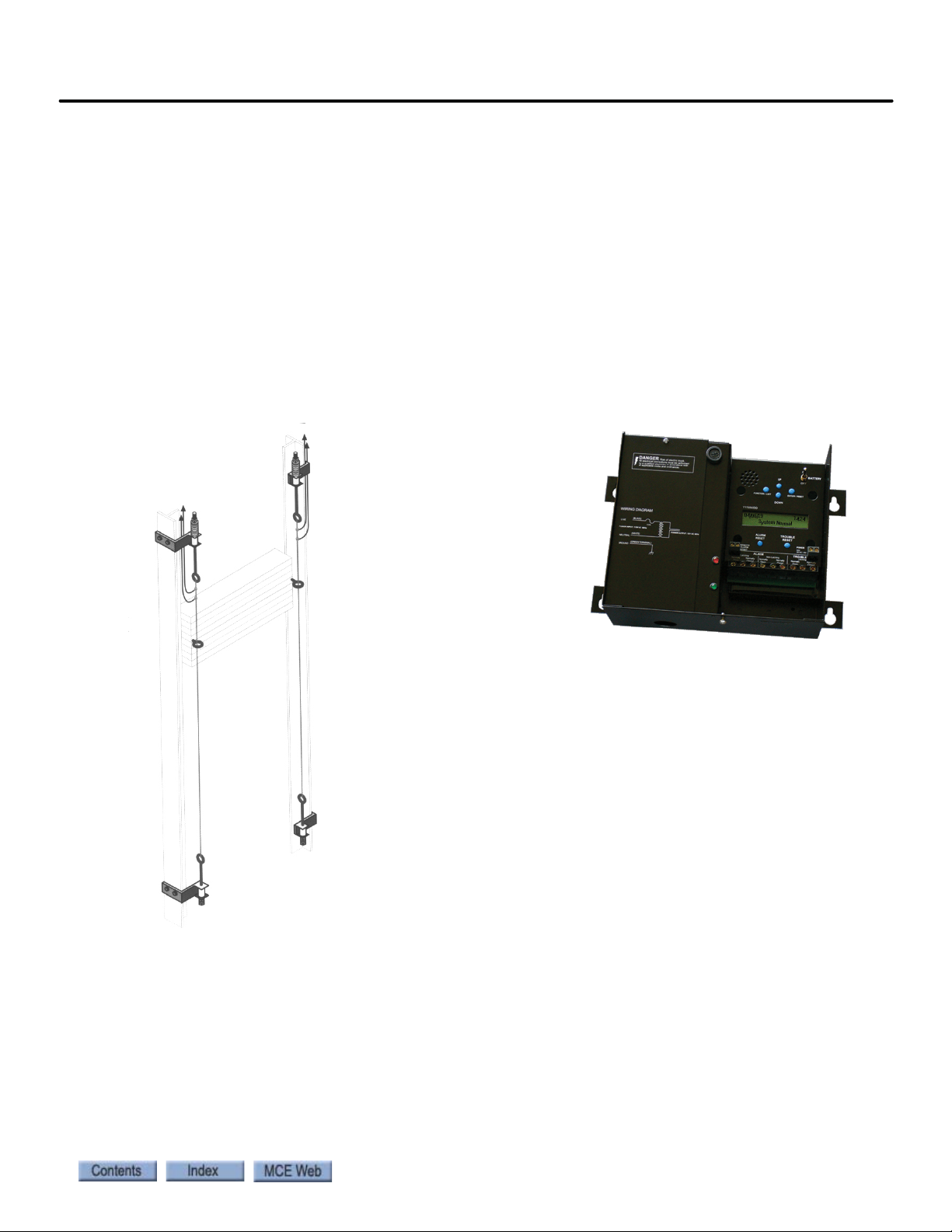
Motion 4000
Counterweight Displacement
Kit:
Two steel cables run parallel
to counterweight guide rails,
passing through a pair of
eyebolts on the counterweight. If the counterweight
moves laterally, the cable
touches the ring, completing
the circuit and providing an
alert to the controller.
Seismic Detector:
Detects and records vertical and horizontal seismic movement. Peak acceleration along each axis is detected
and stored for up to 15 seismic
events. The easy to read LCD displays
real time acceleration and angle of
deflection.
Seismic Equipment
A “ring and string” circuit detects excessive counterweight motion caused by a seismic disturbance. When motion is detected, the car will make a full stop. After stopping, the car will move
to and level at the next available floor in the direction away from the counterweight. After leveling, the car will open its doors and allow passengers to exit.
Modes of operation other than Automatic, for example Fire Phase II or Attendant mode, allow
different operating options when potential counterweight derailment has been detected.
Your job may also use a lateral and/or vertical acceleration sensor to detect seismic activity. At
this point, you should install counterweight movement detection and seismic sensors in accordance with your job prints and seismic monitor manufacturer instructions.
Figure 2.14 Seismic Equipment
Prepare for Inspection Operation
2
2-53
Page 92
Installation
Danger
Running on Inspection Mode
At this point, you should be ready to turn the car over to standard Machine Room and/or Cartop Inspection operation. All equipment, with the exception of the landing/positioning system,
the door operator, load weigher, hall call stations, and full car operating panel should now be
installed and tested for proper function.
Controller inspection warnings:
• As always when actively installing an elevator, have someone stand by the main line disconnect when power is applied or when initial attempts are made to move the car.
• Check all safety circuits are functional.
• Check all hoistway door interlocks are functional.
• Check car gate circuitry is functional.
Prior to Applying Power:
• Verify all circuits are wired to the controller properly.
• Check the following items:
• Inspection switch to INSP
• Verify, with an ohmmeter, that the governor overspeed switch and any other devices that
are wired in at this time will open the safety circuit.
• Physically verify that all hoistway doors are closed and locked.
• Verify that any temporary jumpers placed for equipment that has now been installed are
removed.
Controller Power Up
After powering up the controller, check the following:
1. If the LCD is displaying an error message, troubleshoot to resolve the issue. (Please refer
to Section 5.)
2. Check that the LCD displays INSPECTION.
3. Using the Enable button and the Up/Down toggle, run the car.
4. Release the Enable button and note that machine and brake power are released and that the brake drops and holds the car.
5. Run the car and use the hand-held tach to verify inspection speed.
2-54 Manual # 42-02-2P24
Page 93

Motion 4000
Bypassing Faults on Inspection
Before installation and adjustment are complete, faults that will be adjusted out later may disrupt operation. To bypass faults on Inspection mode:
1. On the MPU board, place switch F3 in the UP position (all others down).
2. On the HC-CTL board, use a jumper to short the pins of JP1 Fault Bypass.
3. Press N until the display shows Controller System Menu.
4. Press S to enter the menu.
5. Press N until the LCD displays Inspection Mode Fault Bypass OFF.
6. Press S to change bypass state to ON.
7. Set F3 back to the DOWN position.
This setting bypasses controller response to faults during Inspection operation. When bypass is
no longer necessary, be certain to change this setting to OFF.
Finishing Installation
With the car running safely on Inspection operation, you are ready to finish installation. This
section describes installing:
Finishing Installation
2
• Landing/positioning system
• Door operator
•Car operating panel
• Fire service peripherals
• Hall Calls
You must also:
• Balance the car and counterweight
• Adjust brake to hold 125% of full load
2-55
Page 94

Installation
Top hanger assembly
(diagonal brace not shown)
LS-TAPEMNTOP-EDGE
Bottom hanger assembly
LS-TAPEMNTBOT-EDGE
Sensor assembly
LS-EDGE
Steel tape, magnets & connecting cables not shown
Together, these are assembly
LS-TAPEMNT-EDGE
Landing/Positioning System
Depending upon job requirements, Motion 4000 may use an encoded magnetic tape landing
system (ELGO) or a perforated steel tape system (LS-EDGE). This section describes both systems. LS-EDGE NEMA 4X/12 systems use stainless steel hoistway components and a sealed
sensor head but are otherwise installed just as are standard systems.
LS-EDGE
The LS-EDGE positioning system uses hall-effect sensors and perforated steel tape to report
position as the car moves through the hoistway. 5.5-inch magnets are used at each door zone;
one row for front openings, a second for rear openings.
The system uses capacitor-stored power and non-volatile memory to retain position information in the event of a power failure, continuing to capture information for 10 seconds after
power loss and storing the final reading for use after power restoration.
The LS-EDGE kit contains the sensor head assembly, an “L” bracket to mount the sensor
assembly to a uni-strut that is in turn attached to the elevator cab (uni-strut to elevator cab not
provided), steel tape, top and bottom steel tape hanger assemblies, the required number of door
zone magnets, and the CAT-5 electrical cables required to connect the sensor to the car top
interface box.
Depending on applicable code, you may have to route electrical connections through conduit. If
so, we recommend minimum 3/4-inch flex so that the modular connectors can slide through
without binding. Perforations for cable tie wrap connection are provided on the RJ-45 plug-end
of the sensor head.
Figure 2.15 LS-EDGE Components
2-56 Manual # 42-02-2P24
Page 95

Motion 4000
Tape Installation
Before installing perforated tape, ensure adequate clearance from beams, walls, counterweight,
cab, and terminal limit devices. Make sure the sensor is not placed so close to the governor lift
arm that, when the car safeties are activated, the sensor is damaged or the car safeties cannot
apply.
• Hang the tape high enough in the hoistway so that, when the counterweight is on a fully
compressed buffer, the sensor assembly will not be damaged by overhead obstructions.
Uni-struts are provided to attach the tape to the rails.
• Attach the tape in the pit low enough so that, when the car is on fully compressed buffer,
the sensor assembly does not contact the bottom hanger assembly.
• Adjust tape spring tension so the tape does not make noise as the car travels up.
• During installation, the edges of the tape sometimes become gouged. After the tape is
installed, use a fine file on the edges of the tape to remove any burrs or gouges. This will
lead to much quieter operation of the encoder system as the car travels at contract speed.
• After smoothing the edges, wipe off all excess oil and dirt from the face of the tape before
installing magnets. Do not use rags that will leave lint on the tape.
Landing/Positioning System
2
2-57
Page 96
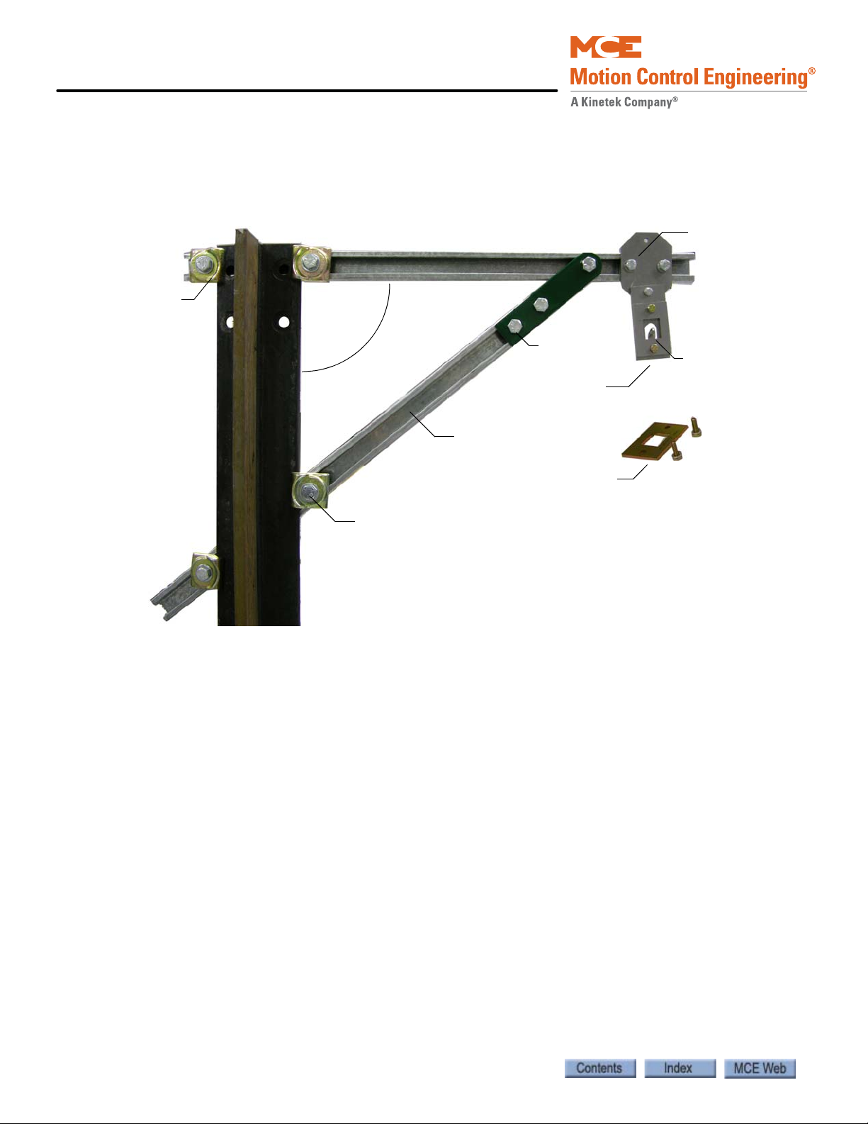
Installation
90 degrees
Ta p e h a n g e r
Hang tape
on tab
19 - 25 ft lbs
40 - 50 ft lbs
40 - 50 ft lbs
30 - 40 ft lbs
Top tape clamp hardware,
10 - 12 ft lbs
LS-TAPESTRUT-EDGE
Top and Bottom Hangers
1. Attach the uni-strut for the top tape hanger across the back of the selected guide rail using the forged rail clips and hardware provided.
2. Attach the diagonal brace as shown below (only provided for tape length exceeding 150 feet).
3. Adjust extended strut length as required (tape suspended as close to the guide rail as
adequate clearances will allow to reduce loading on end of unistrut). Secure rail mounting hardware (40 - 50 ft lbs.). (The tape hanger slides in the strut for fine adjustment
later.)
4. Hook the tape on the protruding tab. Secure the top tape clamp in place (10 - 12 ft lbs.).
5. Record the distance from the rail edge to the tape edge. ________ in/mm.Bottom Hanger
The bottom hanger provides tension to minimize vibration while allowing expansion/contraction across seasonal temperature ranges. Ensure that the tape to rail edge measurement
matches that recorded for the top hanger so that the car tracks the tape accurately. Do not use a
plumb in case the rail stack is not exactly aligned. The scale values are provided as a guideline
only. They are not calibrated. Adjust to suit the installation.
2-58 Manual # 42-02-2P24
Page 97

Motion 4000
Tap e t en si on
gauge
Tension gauge
indicator
Blue oval indicates location of “pre-load”
pin holes allowing you to put tension on
the spring while hanging tape.
Connection torque specifications, Wire AWG
Tape disconnect/break indicator
switch. Wire per job prints.
Tape gripping tab
Switch cam
40 - 50 ft lbs
10 - 12 ft lbs
19 - 25 ft lbs
Figure 2.16 Bottom Hanger Attachment
Landing/Positioning System
2
Tape Detector Switch
The tape detector switch is mounted backwards for protection during shipment. You will need
to remove it and mount it as shown above. Position the switch so that the switch cam holds it
closed when tape tension is adjusted appropriately for the hoistway. Note that switch position
should be adjusted so that the switch is held closed by the cam but not so close that the switch is
held against its mechanical stops. The switch closes at approximately 50% of travel.
Tape Hanging
Work from the cartop to hang the tape from the top hanger and allow it to unroll slowly as you
move the car down the hoistway. It is best to allow the tape to hang and straighten for at least
24-hours before attaching it to the bottom hanger.
2-59
Page 98

Installation
Customer provided uni-strut
CAR TOP
“L” bracket (provided)
LED Indicators UP
40 - 50 ft lbs
Tape Tension
The tape is tensioned according to compression of the bottom tape mount spring. The tension
gauge provides visual indication of low, medium, and high tension positions. Short runs, up to
five floors will generally be acceptable at the low tension position. Runs to 15 floors will generally be acceptable at the medium tension position. Longer runs may require the high tension
position but you should start out with the medium setting first.
Tape tension is intended to reduce noise caused by tape vibration at contract speed. Generally,
you want to use the lowest tension setting that maintains a quiet tape at contract speed.
Sensor Installation
Tape guide side pieces easily detach so the sensor can be slipped onto the steel tape.
Figure 2.17 Sensor with Guide Sides Removed
Figure 2.18 Sensor Mounting
2-60 Manual # 42-02-2P24
Page 99

Motion 4000
Scribe
Line
Top o f
Magnet
2 5/8
inches
Sensor Alignment
After the tape has been installed, check the sensor alignment. The sensor should not ride hard
on either side of the uni-strut bracket during any part of travel through the hoistway. In highrise buildings, if rail alignment varies substantially, it may cause the encoder guides to wear
prematurely. If such misalignment is noted, the installation should be inspected more regularly.
Door Zone, Terminal, and ETS Magnets
5.5-inch strip magnets are used at each floor/opening position. Front and rear magnet alignment is shown on the sensor top label. Looking at the perforated tape from the elevator car, the
magnets for the front door zone are mounted to the left of the perforated holes; magnets for the
rear door zone are mounted to the right of the holes. For Motion 4000 installations, special
magnets marked with a stripe are used at the top and bottom terminals and for ETS magnets if
used.
Figure 2.19 Door Zone Magnet Alignment
Landing/Positioning System
2
2-61
Page 100

Installation
Caution
To mount the door zone magnets:
The magnets must be installed so that they face the front cover of the sensor assembly as
indicated by the diagram on the LED indicator label.
1. Move the elevator level to the highest floor on inspection.
2. Make a mark on the tape even with the top of the sensor assembly. Lower the car one
3. Place the top of the door zone magnet 2 5/8 inches below the scribe mark and to the left
4. Continue mounting door zone magnets as described above for successive floors.
foot.
(front door) or right (rear door) of the perforated holes. For now, simply place the magnets. You can secure them permanently after final adjustments.
2-62 Manual # 42-02-2P24
 Loading...