

Page 1

Motion Control Engineering, Inc.
11380 White Rock Road
Rancho Cordova, CA 95742
voice 916 463 9200
fax 916 463 9201
www.mceinc.com
Motion 2000 Hydraulic Controller V9.xx software
Manual # 42-02-1P21, Rev A9 October 2016
Page 2

Copyright
© 2016, Motion Control Engineering. All Rights Reserved.
This document may not be reproduced, electronically or mechanically, in whole or in part, without
written permission from Motion Control Engineering.
Trademarks
All trademarks or registered product names appearing in this document are the exclusive property
of the respective owners.
Warning and Disclaimer
Although every effort has been made to make this document as complete and accurate as possibl e,
Motion Control Engineering and the document authors, publishers, distributors, and
representatives have neither liability nor responsibility for any loss or damage arising from
information contained in this document or from informational errors or omissions. Information
contained in this document shall not be deemed to constitute a commitme nt to provide service,
equipment, or software by Motion Control Engineering or the document authors, publishers,
distributors, or representatives.
Limited Warranty
Motion Control Engineering (manufacturer) warrants its products for a period of 15 months from
the date of shipment from its factory to be free from defects in workmanship and materials. Any
defect appearing more than 15 months from the date of shipment from the factory shall be
deemed to be due to ordinary wear and tear. Manufac turer, however, assumes no risk or liability for
results of the use of the products purchased from it, including, but without limiting the generality
of the forgoing: (1) The use in combination with any electrical or electronic components, circuits,
systems, assemblies or any other material or equipm ent (2) Unsuitability of this p roduct for use in
any circuit, assembly or environment. Purchasers’ rights under this warr anty shal l consist solely of
requiring the manufacturer to repair, or in manufacturer's sole discretion, replace free of charge,
F.O.B. factory, any defective items received at said factory within the said 15 months and
determined by manufacturer to be defective. The giving of or failure to give any advice or
recommendation by manufacturer shall not constitute any warr anty by or impose any l iability upon
the manufacturer. This warranty constitutes the sole and exclusive remedy of the purchaser and
the exclusive liability of the manufacturer, AND IN LIEU OF ANY AND ALL OTHER WARRANTIES,
EXPRESSED, IMPLIED, OR STAT UTORY AS TO MERCHANTABILITY, FITNESS, FOR PURPOSE SOLD,
DESCRIPTION, QUALITY PRODUCTIVENESS OR ANY OTHER MATTER. In no event will the
manufacturer be liable for special or consequential damages or for delay in performance of this
warranty.
Products that are not manufactured by MCE (such as drives, CR Ts, modems, printers, etc.) are not
covered under the above warranty terms. MCE, however, extends the same warranty terms that
the original manufacturer of such equipment provide with their product (refer to the warranty
terms for such products in their respective manual).
Page 3

End User License Agreement
This End User License Agreement (“Agreement”) grants you the right to use the software contained in this product (the “Software”) subject to the following restrictions: You may not: (i) copy
the Software, except for archive purposes consistent with your standard archive procedures; (ii)
transfer the Software to a third party apart from the entire product; (iii) modify, decompile, disassemble, reverse engineer or otherwise attempt to derive the source code of the Software; (iv)
export the Software or underlying technology in contravention of applicable U.S. and foreign
export laws and regulations; and (v) use the Software other than in connection with operation of
the product.
“LICENSOR'S SUPPLIERS DO NOT MAKE OR PASS ON TO END USER OR ANY OTHER THIRD PARTY ,
ANY EXPRESS, IMPLIED OR STATUTORY WARRANTY OR REPRESENTATION ON BEHALF OF SUCH
SUPPLIERS, INCLUDING BUT NOT LIMITED TO THE IMPLIED WARRANTIES OF NON-INFRINGEMENT, TITLE, MERCHANTABILITY OR FITNESS FOR A PARTICULAR PURPOSE.”
Page 4
Important Precautions and Useful Information
Danger
Caution
Note
Danger
This preface contains information that will help you understand and safely maintain MCE
equipment. We strongly recommend you review this preface and read this manual before
installing, adjusting, or maintaining Motion Control Engineering equipment. This preface discusses:
• Safety and Other Symbol Meanings
• Safety Precautions
• Environmental Considerations
• In this Manual
Safety and Other Symbol Meanings
This manual symbol is used to alert you to procedures, instructions, or situations which, if
not done properly, might result in personal injury or substantial equipment damage.
This manual symbol is used to alert you to procedures, instructions, or situations which, if
not done properly, might result in equipment damage.
This manual symbol is used to alert you to instructions or other immediately helpful informa-
tion.
Safety Precautions
This equipment is designed to comply with ASME A17.1, National Electrical Code, CE, and
CAN/CSA-B44.1/ASME-A17.5 and must be installed by a qualified contractor. It is the
responsibility of the contractor to make sure that the final installation complies with all
local codes and is installed in a safe manner.
This equipment is suitable for use on a circuit capable of delivering not more than 10,000
rms symmetrical amperes, 600 volts maximum. The three-phase AC power supply to the
Drive Isolation Transformer used with this equipment must originate from a fused disconnect switch or circuit brea ker sized in conform ance to all applicable national, state, and local
electrical codes in order to provide the necessary motor branch circuit protection for the
Drive Unit and motor. Incorrect motor branch circuit protection will void the warranty and
may create a hazardous condition.
Page 5

Proper grounding is vitally important to safe and successful operation. Bring your ground
wire to the system subplate. You must choose the proper conductor size and minimize the
resistance to ground by using the shortest possible routing. See National Electrical Code
Article 250-95 or the applicable local electrical code.
Before applying power to the controller, physically check all the power resistors and other
components located in the resistor cabinet and inside the controller. Components loosened
during shipment may cause damage.
For proper operation of your controller, you must make sure that: 1) A direct solid ground is
provided in the machine room to properly ground the controller and motor. Indirect
grounds such as the building structure or a water pipe may not provide proper grounding
and could act as an antenna to radiate RFI noise, thus disturbing sensitive equipment in the
building. Improper grounding may also render any RFI filter ineffective. 2) The incoming
power to the controller and the outgoing power wires to the motor are in their respective,
separate, grounded conduits.
This equipment may contain voltages as high as 1000 volts. Use extreme caution. Do not
touch any components, resistors, circuit boards, power devices, or electrical connections
without ensuring that high voltage is not present.
Environmental Considerations
• Keep the machine room clean.
•Controllers are generally in NEMA 1 enclosures.
• Do not install the controller in a dusty area.
• Do not install the controller in a carpeted area.
• Keep room temperature between 32 and 104 degrees F (0 to 40 degrees C).
• Prevent condensation on the equipment.
• Do not install the controller in a hazardous location or where excessive amounts of
vapors or chemical fumes may be present.
• Make certain that power line fluctuations are within plus or minus 10% of proper value.
Air Conditioned Equipment Cabinets
If your control or group enclosure is equipped with an air conditioning unit, it is very important
to observe the following precautions. (Failure to do so can result in moisture damage to electrical components.)
• Maintain the integrity of the cabinet by using sealed knockouts and sealing any holes
made during installation.
• Do not run the air conditioning while the cabinet doors are open.
• If you turn the air conditioner off while it is running, wait at least five minutes before
restarting it. Otherwise, the compressor may be damaged.
• Observe the recommended thermostat setting (75 degrees) and follow recommended
maintenance schedules.
• Make certain that the air conditioning drain tube remains clear to avoid water accumulation in the unit.
Page 6

In This Manual:
This manual is the installation, adjustment, and troubleshooting guide for the HMC-2000 car
control. When viewed online as a pdf file, hyperlinks (buttons or blue text) link to related topics
and informational websites. The manual includes:
• Contents: Table of Contents. When viewed online as a pdf file, hyperlinks in the Contents
link to the associated topic in the body of the manual.
• Section 1. Motion 2000 Description: A description of the Motion 2000 controller and
circuit boards.
• Section 2. Installation: Installation and wiring guidelines.
• Section 3. Startup - Inspection Operation: Controller startup, operation on Inspection,
installation of hoistway equipment and preparing the car to run on Test/Normal operation.
• Section 4. Final Adjustment: A description of absolute floor encoding and Test mode
operation. Running the car on Test and Normal operation and making the final checks
and adjustments prior to releasing the car to normal operation.
• Section 5. The Computer: How to use the MPU to program and troubleshoot the controller. Complete with parameter definitions where appropriate.
• Section 6. Troubleshooting: This section includes Status and Error Messages, PC Board
Quick References and Data Trap instructions.
• Section 7. Appendix: Record of Parameter Values, Security Codes, LS-QUTE Landing
System.
• Index: Alphabetical index to help you find information in the manual. When viewed
online as a pdf file, index entry page references are hyperlinks to the associated information in the body of the manual.
Page 7

Contents
Important Precautions and Useful Information
Safety and Other Symbol Meanings . . . . . . . . . . . . . . . . . . . . . . . . . . . . . . . . . . . 1-iv
Safety Precautions . . . . . . . . . . . . . . . . . . . . . . . . . . . . . . . . . . . . . . . . . . . . . . . . . 1-iv
Environmental Considerations . . . . . . . . . . . . . . . . . . . . . . . . . . . . . . . . . . . . . . . 1-v
Air Conditioned Equipment Cabinets . . . . . . . . . . . . . . . . . . . . . . . . . . . . . . . . . . . . . . . . . . .1-v
In This Manual: . . . . . . . . . . . . . . . . . . . . . . . . . . . . . . . . . . . . . . . . . . . . . . . . . . . 1-vi
Section 1. Motion 2000 TSSA Description
General Information . . . . . . . . . . . . . . . . . . . . . . . . . . . . . . . . . . . . . . . . . . . . . . . . 1-1
Car Controller Description . . . . . . . . . . . . . . . . . . . . . . . . . . . . . . . . . . . . . . . . . . . 1-3
Controller Circuit Boards . . . . . . . . . . . . . . . . . . . . . . . . . . . . . . . . . . . . . . . . . . . . . . . . . . . . .1-5
Landing System . . . . . . . . . . . . . . . . . . . . . . . . . . . . . . . . . . . . . . . . . . . . . . . . . . . . 1-9
LS-QUTE Landing System . . . . . . . . . . . . . . . . . . . . . . . . . . . . . . . . . . . . . . . . . . . . . . . . . . . 1-9
LS-STAN Landing System . . . . . . . . . . . . . . . . . . . . . . . . . . . . . . . . . . . . . . . . . . . . . . . . . . . .1-10
LS-EDGE Landing System . . . . . . . . . . . . . . . . . . . . . . . . . . . . . . . . . . . . . . . . . . . . . . . . . . . 1-11
Operating Mode Descriptions . . . . . . . . . . . . . . . . . . . . . . . . . . . . . . . . . . . . . . . 1-12
Automatic Operation . . . . . . . . . . . . . . . . . . . . . . . . . . . . . . . . . . . . . . . . . . . . . . . . . . . . . . . .1-12
Mode Entry. . . . . . . . . . . . . . . . . . . . . . . . . . . . . . . . . . . . . . . . . . . . . . . . . . . . . . . . . . . . . 1-12
Inspection Operation . . . . . . . . . . . . . . . . . . . . . . . . . . . . . . . . . . . . . . . . . . . . . . . . . . . . . . . .1-13
Cartop Inspection . . . . . . . . . . . . . . . . . . . . . . . . . . . . . . . . . . . . . . . . . . . . . . . . . . . . . . . 1-13
In Car Inspection . . . . . . . . . . . . . . . . . . . . . . . . . . . . . . . . . . . . . . . . . . . . . . . . . . . . . . . . 1-13
Machine Room Inspection . . . . . . . . . . . . . . . . . . . . . . . . . . . . . . . . . . . . . . . . . . . . . . . . 1-14
Hoistway Access Inspection . . . . . . . . . . . . . . . . . . . . . . . . . . . . . . . . . . . . . . . . . . . . . . . 1-14
Attendant Service Operation . . . . . . . . . . . . . . . . . . . . . . . . . . . . . . . . . . . . . . . . . . . . . . . . .1-15
Mode Entry. . . . . . . . . . . . . . . . . . . . . . . . . . . . . . . . . . . . . . . . . . . . . . . . . . . . . . . . . . . . . 1-15
Independent Service Operation . . . . . . . . . . . . . . . . . . . . . . . . . . . . . . . . . . . . . . . . . . . . . . .1-15
Mode Entry. . . . . . . . . . . . . . . . . . . . . . . . . . . . . . . . . . . . . . . . . . . . . . . . . . . . . . . . . . . . . 1-15
Sabbath Operation . . . . . . . . . . . . . . . . . . . . . . . . . . . . . . . . . . . . . . . . . . . . . . . . . . . . . . . . . .1-16
Emergency Medical Operation . . . . . . . . . . . . . . . . . . . . . . . . . . . . . . . . . . . . . . . . . . . . . . . .1-16
Hospital Service Operation . . . . . . . . . . . . . . . . . . . . . . . . . . . . . . . . . . . . . . . . . . . . . . . . . . .1-17
Fire Service Operation . . . . . . . . . . . . . . . . . . . . . . . . . . . . . . . . . . . . . . . . . . . . . . . . . . . . . . .1-17
i
Page 8

Emergency Power Operation . . . . . . . . . . . . . . . . . . . . . . . . . . . . . . . . . . . . . . . . . . . . . . . . .1-18
Generator Backup . . . . . . . . . . . . . . . . . . . . . . . . . . . . . . . . . . . . . . . . . . . . . . . . . . . . . . . 1-18
EPS Backup . . . . . . . . . . . . . . . . . . . . . . . . . . . . . . . . . . . . . . . . . . . . . . . . . . . . . . . . . . . . 1-18
Car Recall . . . . . . . . . . . . . . . . . . . . . . . . . . . . . . . . . . . . . . . . . . . . . . . . . . . . . . . . . . . . . . . . .1-18
Capture for Test (Pretest) . . . . . . . . . . . . . . . . . . . . . . . . . . . . . . . . . . . . . . . . . . . . . . . . . . . .1-19
Test Mode . . . . . . . . . . . . . . . . . . . . . . . . . . . . . . . . . . . . . . . . . . . . . . . . . . . . . . . . . . . . . . . . .1-19
Monitoring and Control Options . . . . . . . . . . . . . . . . . . . . . . . . . . . . . . . . . . . . .1-20
iMonitor . . . . . . . . . . . . . . . . . . . . . . . . . . . . . . . . . . . . . . . . . . . . . . . . . . . . . . . . . . . . . . . . . 1-20
iReport . . . . . . . . . . . . . . . . . . . . . . . . . . . . . . . . . . . . . . . . . . . . . . . . . . . . . . . . . . . . . . . . . . . 1-20
BMS-Link . . . . . . . . . . . . . . . . . . . . . . . . . . . . . . . . . . . . . . . . . . . . . . . . . . . . . . . . . . . . . . . . .1-21
Motion Portable Adjustment Control (mPAC) . . . . . . . . . . . . . . . . . . . . . . . . . . . . . . . . . . .1-21
mView . . . . . . . . . . . . . . . . . . . . . . . . . . . . . . . . . . . . . . . . . . . . . . . . . . . . . . . . . . . . . . . . . . . 1-22
Section 2. Installation
In this Section . . . . . . . . . . . . . . . . . . . . . . . . . . . . . . . . . . . . . . . . . . . . . . . . . . . . . . 2-1
Safety Precautions . . . . . . . . . . . . . . . . . . . . . . . . . . . . . . . . . . . . . . . . . . . . . . . . . .2-2
Personal Safety. . . . . . . . . . . . . . . . . . . . . . . . . . . . . . . . . . . . . . . . . . . . . . . . . . . . . . . . . . . 2-2
Equipment Safety. . . . . . . . . . . . . . . . . . . . . . . . . . . . . . . . . . . . . . . . . . . . . . . . . . . . . . . . . 2-2
Installation Considerations . . . . . . . . . . . . . . . . . . . . . . . . . . . . . . . . . . . . . . . . . .2-3
Machine Room Preparation . . . . . . . . . . . . . . . . . . . . . . . . . . . . . . . . . . . . . . . . . . . . . . . . . . 2-3
Piping and Wiring . . . . . . . . . . . . . . . . . . . . . . . . . . . . . . . . . . . . . . . . . . . . . . . . . . . . . . . . . . 2-4
How Electrical Noise Occurs . . . . . . . . . . . . . . . . . . . . . . . . . . . . . . . . . . . . . . . . . . . . . . . 2-4
How to Avoid Electrical Noise Problems . . . . . . . . . . . . . . . . . . . . . . . . . . . . . . . . . . . . . 2-4
Possible EMI/RFI Interference . . . . . . . . . . . . . . . . . . . . . . . . . . . . . . . . . . . . . . . . . . . . . 2-4
Recommended Tools and Test Equipment . . . . . . . . . . . . . . . . . . . . . . . . . . . . . . . . . . . . . 2-5
Wiring Prints . . . . . . . . . . . . . . . . . . . . . . . . . . . . . . . . . . . . . . . . . . . . . . . . . . . . . . . . . . . . . . 2-5
Drawing Number Format . . . . . . . . . . . . . . . . . . . . . . . . . . . . . . . . . . . . . . . . . . . . . . . . . . 2-5
Nomenclature. . . . . . . . . . . . . . . . . . . . . . . . . . . . . . . . . . . . . . . . . . . . . . . . . . . . . . . . . . . . 2-6
Controller Installation . . . . . . . . . . . . . . . . . . . . . . . . . . . . . . . . . . . . . . . . . . . . . .2-7
Controller Wiring Guidelines . . . . . . . . . . . . . . . . . . . . . . . . . . . . . . . . . . . . . . . . . . . . . . . . . 2-7
General Wiring Guidelines . . . . . . . . . . . . . . . . . . . . . . . . . . . . . . . . . . . . . . . . . .2-8
Proper Grounding Procedures . . . . . . . . . . . . . . . . . . . . . . . . . . . . . . . . . . . . . . . . . . . . . . . . 2-8
Wiring Connections for Properly Grounded Systems . . . . . . . . . . . . . . . . . . . . . . . . . . . 2-8
Ground Wiring . . . . . . . . . . . . . . . . . . . . . . . . . . . . . . . . . . . . . . . . . . . . . . . . . . . . . . . . . . . . 2-9
Main AC Power . . . . . . . . . . . . . . . . . . . . . . . . . . . . . . . . . . . . . . . . . . . . . . . . . . . . . . . . . . . . . 2-9
Pump Motor Wiring . . . . . . . . . . . . . . . . . . . . . . . . . . . . . . . . . . . . . . . . . . . . . . . . . . . . . . . . 2-9
Low Voltage Signal Wiring . . . . . . . . . . . . . . . . . . . . . . . . . . . . . . . . . . . . . . . . . . . . . . . . . . 2-10
Traveling Cable Wiring . . . . . . . . . . . . . . . . . . . . . . . . . . . . . . . . . . . . . . . . . . . . . . . . . . . . . 2-10
Section 3. Startup - Inspection Operation
In this Section . . . . . . . . . . . . . . . . . . . . . . . . . . . . . . . . . . . . . . . . . . . . . . . . . . . . . . 3-1
Check for Shorts to Ground . . . . . . . . . . . . . . . . . . . . . . . . . . . . . . . . . . . . . . . . . .3-2
Before Applying Power . . . . . . . . . . . . . . . . . . . . . . . . . . . . . . . . . . . . . . . . . . . . . .3-2
ii Manual # 42-02-1P21
Page 9

Applying Power . . . . . . . . . . . . . . . . . . . . . . . . . . . . . . . . . . . . . . . . . . . . . . . . . . . .3-3
Initial Adjustments and Power Phasing . . . . . . . . . . . . . . . . . . . . . . . . . . . . . . . . . . . . . . . . 3-3
Set Up for Construction Operation . . . . . . . . . . . . . . . . . . . . . . . . . . . . . . . . . . . .3-4
Required Connections . . . . . . . . . . . . . . . . . . . . . . . . . . . . . . . . . . . . . . . . . . . . . . . . . . . . . . . 3-4
Temporary Jumpers . . . . . . . . . . . . . . . . . . . . . . . . . . . . . . . . . . . . . . . . . . . . . . . . . . . . . . 3-5
Resolving Faults. . . . . . . . . . . . . . . . . . . . . . . . . . . . . . . . . . . . . . . . . . . . . . . . . . . . . . . . . . 3-5
Temporary Run Box Hookup . . . . . . . . . . . . . . . . . . . . . . . . . . . . . . . . . . . . . . . . . . . . . . . 3-6
Verifying Proper Starter Operation . . . . . . . . . . . . . . . . . . . . . . . . . . . . . . . . . . .3-7
Hoistway Control Equipment Installation . . . . . . . . . . . . . . . . . . . . . . . . . . . . . .3-9
Installing the LS-QUTE Landing System . . . . . . . . . . . . . . . . . . . . . . . . . . . . . . . . . . . . . . . 3-9
Installing the LS-QUTE Landing System Control Box . . . . . . . . . . . . . . . . . . . . . . . . . . 3-9
Installing the Magnetic Strips on LS-QUTE Steel Tape . . . . . . . . . . . . . . . . . . . . . . . . 3-10
Installing the LS-QUTE Hoistway Limit Switches. . . . . . . . . . . . . . . . . . . . . . . . . . . . . 3-10
LS-EDGE Installation . . . . . . . . . . . . . . . . . . . . . . . . . . . . . . . . . . . . . . . . . . . . . . . . . . . . . . .3-11
LS-EDGE Tape Installation . . . . . . . . . . . . . . . . . . . . . . . . . . . . . . . . . . . . . . . . . . . . . . . 3-12
LS-EDGE Top Hanger Assembly . . . . . . . . . . . . . . . . . . . . . . . . . . . . . . . . . . . . . . . . . . . 3-12
LS-EDGE Bottom Hanger Assembly . . . . . . . . . . . . . . . . . . . . . . . . . . . . . . . . . . . . . . . . 3-13
LS-EDGE Broken Tape Switch. . . . . . . . . . . . . . . . . . . . . . . . . . . . . . . . . . . . . . . . . . . . . 3-14
Hanging the Tape. . . . . . . . . . . . . . . . . . . . . . . . . . . . . . . . . . . . . . . . . . . . . . . . . . . . . . . . 3-14
LS-EDGE Sensor Installation. . . . . . . . . . . . . . . . . . . . . . . . . . . . . . . . . . . . . . . . . . . . . . 3-14
LS-EDGE Door Zone Magnets . . . . . . . . . . . . . . . . . . . . . . . . . . . . . . . . . . . . . . . . . . . . . 3-16
LS-EDGE Terminal Magnets . . . . . . . . . . . . . . . . . . . . . . . . . . . . . . . . . . . . . . . . . . . . . . 3-17
LS-EDGE Terminal Magnet Logic . . . . . . . . . . . . . . . . . . . . . . . . . . . . . . . . . . . . . . . . . . 3-19
LS-EDGE Electrical Connection . . . . . . . . . . . . . . . . . . . . . . . . . . . . . . . . . . . . . . . . . . . . . . 3-19
Parameter Settings . . . . . . . . . . . . . . . . . . . . . . . . . . . . . . . . . . . . . . . . . . . . . . . . . . . . . . . . . 3-19
Hoistway Learn Operation . . . . . . . . . . . . . . . . . . . . . . . . . . . . . . . . . . . . . . . . . 3-20
Adjusting Floor Heights . . . . . . . . . . . . . . . . . . . . . . . . . . . . . . . . . . . . . . . . . . . . . . . . . . 3-20
Initial Stepping Distances. . . . . . . . . . . . . . . . . . . . . . . . . . . . . . . . . . . . . . . . . . . . . . . . . 3-20
Door Position Monitor Switch (If used) . . . . . . . . . . . . . . . . . . . . . . . . . . . . . . . . . . . . . 3-20
LS-EDGE Short Floors . . . . . . . . . . . . . . . . . . . . . . . . . . . . . . . . . . . . . . . . . . . . . . . . . . . . . 3-21
Door Zone Verification . . . . . . . . . . . . . . . . . . . . . . . . . . . . . . . . . . . . . . . . . . . . . . . . . . . . . 3-21
Permanently Attach Magnets . . . . . . . . . . . . . . . . . . . . . . . . . . . . . . . . . . . . . . . . . . . . . . . . 3-21
Complete the Installation and Field Wiring . . . . . . . . . . . . . . . . . . . . . . . . . . . .3-22
Preparing the Car to Run on Test/Normal Mode . . . . . . . . . . . . . . . . . . . . . . . 3-22
Section 4. Final Adjustment
In this Section . . . . . . . . . . . . . . . . . . . . . . . . . . . . . . . . . . . . . . . . . . . . . . . . . . . . . .4-1
Diagnostic Messages and Input/Output Signals . . . . . . . . . . . . . . . . . . . . . . . . . . . . . . . . . 4-2
Onboard Diagnostics. . . . . . . . . . . . . . . . . . . . . . . . . . . . . . . . . . . . . . . . . . . . . . . . . . . . . . 4-2
Absolute Floor Encoding . . . . . . . . . . . . . . . . . . . . . . . . . . . . . . . . . . . . . . . . . . . . . . . . . . . . . 4-2
Registering Car Calls . . . . . . . . . . . . . . . . . . . . . . . . . . . . . . . . . . . . . . . . . . . . . . . .4-3
Test Mode Operation . . . . . . . . . . . . . . . . . . . . . . . . . . . . . . . . . . . . . . . . . . . . . . . . . . . . . . . . 4-4
Running on Test/Normal Mode . . . . . . . . . . . . . . . . . . . . . . . . . . . . . . . . . . . . . . .4-5
iii
Page 10

Final Adjustments on Test Mode . . . . . . . . . . . . . . . . . . . . . . . . . . . . . . . . . . . . . .4-6
Hydraulic Valves . . . . . . . . . . . . . . . . . . . . . . . . . . . . . . . . . . . . . . . . . . . . . . . . . . . . . . . . . . . 4-6
Slowdown and Limit Switches . . . . . . . . . . . . . . . . . . . . . . . . . . . . . . . . . . . . . . . . . . . . . . . . 4-6
Motor Limit Timer . . . . . . . . . . . . . . . . . . . . . . . . . . . . . . . . . . . . . . . . . . . . . . . . . . . . . . . . . . 4-6
Valve Limit Timer . . . . . . . . . . . . . . . . . . . . . . . . . . . . . . . . . . . . . . . . . . . . . . . . . . . . . . . . . . 4-6
Relevel Operation . . . . . . . . . . . . . . . . . . . . . . . . . . . . . . . . . . . . . . . . . . . . . . . . . . . . . . . . . . . 4-6
Final Adjustments on Independent Service . . . . . . . . . . . . . . . . . . . . . . . . . . . . .4-7
Door Operator Adjustments . . . . . . . . . . . . . . . . . . . . . . . . . . . . . . . . . . . . . . . . . . . . . . . . . . 4-7
Door Open/Close Protection . . . . . . . . . . . . . . . . . . . . . . . . . . . . . . . . . . . . . . . . . . . . . . . . . 4-7
Final Adjustments on Normal Operation . . . . . . . . . . . . . . . . . . . . . . . . . . . . . . 4-8
Hall Calls . . . . . . . . . . . . . . . . . . . . . . . . . . . . . . . . . . . . . . . . . . . . . . . . . . . . . . . . . . . . . . . . . . 4-8
Ride and Performance . . . . . . . . . . . . . . . . . . . . . . . . . . . . . . . . . . . . . . . . . . . . . . . . . . . . . . . 4-8
Recheck . . . . . . . . . . . . . . . . . . . . . . . . . . . . . . . . . . . . . . . . . . . . . . . . . . . . . . . . . . . . . . . . . . . 4-8
Options . . . . . . . . . . . . . . . . . . . . . . . . . . . . . . . . . . . . . . . . . . . . . . . . . . . . . . . . . . . . . . . . . . . 4-8
Random Call Testing . . . . . . . . . . . . . . . . . . . . . . . . . . . . . . . . . . . . . . . . . . . . . . . . . . . . . . . . 4-8
Remote Governor Testing (Roped Hydro) . . . . . . . . . . . . . . . . . . . . . . . . . . . . . . . . . . . . . . 4-9
Static Testing:. . . . . . . . . . . . . . . . . . . . . . . . . . . . . . . . . . . . . . . . . . . . . . . . . . . . . . . . . . . . 4-9
Dynamic Testing:. . . . . . . . . . . . . . . . . . . . . . . . . . . . . . . . . . . . . . . . . . . . . . . . . . . . . . . . . 4-9
Final Testing, LS-EDGE Only . . . . . . . . . . . . . . . . . . . . . . . . . . . . . . . . . . . . . . . .4-10
Bottom Terminal Test . . . . . . . . . . . . . . . . . . . . . . . . . . . . . . . . . . . . . . . . . . . . . . . . . . . . . . 4-10
Top Terminal Test . . . . . . . . . . . . . . . . . . . . . . . . . . . . . . . . . . . . . . . . . . . . . . . . . . . . . . . . . 4-10
Restore Original Settings . . . . . . . . . . . . . . . . . . . . . . . . . . . . . . . . . . . . . . . . . . . . . . . . . . . 4-10
Release to Normal Operation . . . . . . . . . . . . . . . . . . . . . . . . . . . . . . . . . . . . . . . . 4-11
Section 5. The Computer
In this Section . . . . . . . . . . . . . . . . . . . . . . . . . . . . . . . . . . . . . . . . . . . . . . . . . . . . . . 5-1
The HC-MPU Main Processor Unit . . . . . . . . . . . . . . . . . . . . . . . . . . . . . . . . . . . .5-2
Indicators . . . . . . . . . . . . . . . . . . . . . . . . . . . . . . . . . . . . . . . . . . . . . . . . . . . . . . . . . . . . . . . 5-2
Switches, Buttons & Adjustments . . . . . . . . . . . . . . . . . . . . . . . . . . . . . . . . . . . . . . . . . . . 5-3
Connectors . . . . . . . . . . . . . . . . . . . . . . . . . . . . . . . . . . . . . . . . . . . . . . . . . . . . . . . . . . . . . . 5-4
Status Displays. . . . . . . . . . . . . . . . . . . . . . . . . . . . . . . . . . . . . . . . . . . . . . . . . . . . . . . . . . . 5-4
Computer Security . . . . . . . . . . . . . . . . . . . . . . . . . . . . . . . . . . . . . . . . . . . . . . . . . .5-5
Password. . . . . . . . . . . . . . . . . . . . . . . . . . . . . . . . . . . . . . . . . . . . . . . . . . . . . . . . . . . . . . . . 5-5
Diagnostic Mode . . . . . . . . . . . . . . . . . . . . . . . . . . . . . . . . . . . . . . . . . . . . . . . . . . . .5-6
Getting into Diagnostic Mode . . . . . . . . . . . . . . . . . . . . . . . . . . . . . . . . . . . . . . . . . . . . . . 5-6
Function of N Push Button. . . . . . . . . . . . . . . . . . . . . . . . . . . . . . . . . . . . . . . . . . . . . . . . . 5-6
Function of S Push Button . . . . . . . . . . . . . . . . . . . . . . . . . . . . . . . . . . . . . . . . . . . . . . . . . 5-6
Function of + Push Button . . . . . . . . . . . . . . . . . . . . . . . . . . . . . . . . . . . . . . . . . . . . . . . . . 5-6
Function of - Push Button. . . . . . . . . . . . . . . . . . . . . . . . . . . . . . . . . . . . . . . . . . . . . . . . . . 5-6
Format of LCD Display . . . . . . . . . . . . . . . . . . . . . . . . . . . . . . . . . . . . . . . . . . . . . . . . . . . . 5-7
Troubleshooting Using the Computer's Internal Memory . . . . . . . . . . . . . . . . . . . . . . . 5-9
Troubleshooting Specific Problems. . . . . . . . . . . . . . . . . . . . . . . . . . . . . . . . . . . . . . . . . 5-12
Setting Parameters (Options) to Default Values . . . . . . . . . . . . . . . . . . . . . . . . . . . . 5-13
iv Manual # 42-02-1P21
Page 11

F1: Program Mode . . . . . . . . . . . . . . . . . . . . . . . . . . . . . . . . . . . . . . . . . . . . . . . . .5-14
General Description of Program Mode . . . . . . . . . . . . . . . . . . . . . . . . . . . . . . . . . . . . . . . . 5-14
Viewing Menus on the LCD Display . . . . . . . . . . . . . . . . . . . . . . . . . . . . . . . . . . . . . . . . 5-14
Viewing Options Within a Menu. . . . . . . . . . . . . . . . . . . . . . . . . . . . . . . . . . . . . . . . . . 5-15
Changing a Value . . . . . . . . . . . . . . . . . . . . . . . . . . . . . . . . . . . . . . . . . . . . . . . . . . . . . . . . 5-15
Saving the New Values . . . . . . . . . . . . . . . . . . . . . . . . . . . . . . . . . . . . . . . . . . . . . . . . . . . 5-15
Restoring Original Values. . . . . . . . . . . . . . . . . . . . . . . . . . . . . . . . . . . . . . . . . . . . . . . . . 5-15
Step-by-Step Example . . . . . . . . . . . . . . . . . . . . . . . . . . . . . . . . . . . . . . . . . . . . . . . . . . . 5-16
Basic Feature Menu Options . . . . . . . . . . . . . . . . . . . . . . . . . . . . . . . . . . . . . . . . . . . . . . . . . .5-17
Fire Service Menu Options . . . . . . . . . . . . . . . . . . . . . . . . . . . . . . . . . . . . . . . . . . . . . . . . . . 5-20
Door Operation Menu Options . . . . . . . . . . . . . . . . . . . . . . . . . . . . . . . . . . . . . . . . . . . . . . . 5-22
Timer Menu Options . . . . . . . . . . . . . . . . . . . . . . . . . . . . . . . . . . . . . . . . . . . . . . . . . . . . . . . 5-26
Gongs/Lanterns Menu Options . . . . . . . . . . . . . . . . . . . . . . . . . . . . . . . . . . . . . . . . . . . . . . 5-28
Spare Inputs Menu Options . . . . . . . . . . . . . . . . . . . . . . . . . . . . . . . . . . . . . . . . . . . . . . . . . 5-29
Viewing and Assigning Spare Inputs. . . . . . . . . . . . . . . . . . . . . . . . . . . . . . . . . . . . . . . . 5-29
Spare Outputs Menu Options . . . . . . . . . . . . . . . . . . . . . . . . . . . . . . . . . . . . . . . . . . . . . . . . 5-39
Viewing and Assigning Spare Outputs . . . . . . . . . . . . . . . . . . . . . . . . . . . . . . . . . . . . . . 5-39
Extra Features Menu Options . . . . . . . . . . . . . . . . . . . . . . . . . . . . . . . . . . . . . . . . . . . . . . . . 5-48
UIO Board/Security Enforcement/Connection Order . . . . . . . . . . . . . . . . . . . . . . . . . 5-49
Additional Car Options Menu . . . . . . . . . . . . . . . . . . . . . . . . . . . . . . . . . . . . . . . . . . . . . . . 5-54
Timed Features . . . . . . . . . . . . . . . . . . . . . . . . . . . . . . . . . . . . . . . . . . . . . . . . . . . . . . . . . . . . 5-55
F2: External Memory Mode . . . . . . . . . . . . . . . . . . . . . . . . . . . . . . . . . . . . . . . . .5-56
Getting Into External Memory Mode . . . . . . . . . . . . . . . . . . . . . . . . . . . . . . . . . . . . . . . 5-56
Function of N Push Button. . . . . . . . . . . . . . . . . . . . . . . . . . . . . . . . . . . . . . . . . . . . . . . . 5-56
Function of S Push Button . . . . . . . . . . . . . . . . . . . . . . . . . . . . . . . . . . . . . . . . . . . . . . . . 5-56
Function of + Push Button . . . . . . . . . . . . . . . . . . . . . . . . . . . . . . . . . . . . . . . . . . . . . . . . 5-56
Function of – Push Button . . . . . . . . . . . . . . . . . . . . . . . . . . . . . . . . . . . . . . . . . . . . . . . . 5-56
Troubleshooting Using External Memory Mode . . . . . . . . . . . . . . . . . . . . . . . . . . . . . . 5-57
F3: System Mode . . . . . . . . . . . . . . . . . . . . . . . . . . . . . . . . . . . . . . . . . . . . . . . . . 5-60
Building Security Menu . . . . . . . . . . . . . . . . . . . . . . . . . . . . . . . . . . . . . . . . . . . . . . . . . . . . . 5-60
Passcode Request Menu . . . . . . . . . . . . . . . . . . . . . . . . . . . . . . . . . . . . . . . . . . . . . . . . . . . . 5-62
Load Weigher Thresholds . . . . . . . . . . . . . . . . . . . . . . . . . . . . . . . . . . . . . . . . . . . . . . . . . . . 5-63
Adjusting the Load Thresholds . . . . . . . . . . . . . . . . . . . . . . . . . . . . . . . . . . . . . . . . . . . . 5-63
Analog Load Weigher Learn Function . . . . . . . . . . . . . . . . . . . . . . . . . . . . . . . . . . . . . . . . . 5-64
Controller System Menu . . . . . . . . . . . . . . . . . . . . . . . . . . . . . . . . . . . . . . . . . . . . . . . . . . . 5-66
F4: Messages and Floor Labels . . . . . . . . . . . . . . . . . . . . . . . . . . . . . . . . . . . . . .5-67
F5: Controller Utilities/Monitoring and Reporting . . . . . . . . . . . . . . . . . . . . 5-69
Controller Utilities Menu . . . . . . . . . . . . . . . . . . . . . . . . . . . . . . . . . . . . . . . . . . . . . . . . . . . 5-69
Registering Front or Rear Car Calls. . . . . . . . . . . . . . . . . . . . . . . . . . . . . . . . . . . . . . . . . 5-69
Date/Time. . . . . . . . . . . . . . . . . . . . . . . . . . . . . . . . . . . . . . . . . . . . . . . . . . . . . . . . . . . . . . 5-70
View Event Log. . . . . . . . . . . . . . . . . . . . . . . . . . . . . . . . . . . . . . . . . . . . . . . . . . . . . . . . . . 5-71
Clear Event Log . . . . . . . . . . . . . . . . . . . . . . . . . . . . . . . . . . . . . . . . . . . . . . . . . . . . . . . . . 5-72
CTL Diagnostic Menu . . . . . . . . . . . . . . . . . . . . . . . . . . . . . . . . . . . . . . . . . . . . . . . . . . . . 5-72
EDG Diagnostics . . . . . . . . . . . . . . . . . . . . . . . . . . . . . . . . . . . . . . . . . . . . . . . . . . . . . . . . 5-73
CTL A Diagnostics . . . . . . . . . . . . . . . . . . . . . . . . . . . . . . . . . . . . . . . . . . . . . . . . . . . . . . . 5-78
CTL B Diagnostics . . . . . . . . . . . . . . . . . . . . . . . . . . . . . . . . . . . . . . . . . . . . . . . . . . . . . . . 5-88
System CAN Bus . . . . . . . . . . . . . . . . . . . . . . . . . . . . . . . . . . . . . . . . . . . . . . . . . . . . . . . . 5-97
v
Page 12

Monitoring and Reporting Menu . . . . . . . . . . . . . . . . . . . . . . . . . . . . . . . . . . . . . . . . . . . . . 5-98
Diagnostics, Refresh, Reset . . . . . . . . . . . . . . . . . . . . . . . . . . . . . . . . . . . . . . . . . . . . . . . 5-98
F6: Hoistway Learn Operations . . . . . . . . . . . . . . . . . . . . . . . . . . . . . . . . . . . . 5-100
LS-EDGE Steel Tape . . . . . . . . . . . . . . . . . . . . . . . . . . . . . . . . . . . . . . . . . . . . . . . . . . . . . . 5-100
Adjusting Floor Heights . . . . . . . . . . . . . . . . . . . . . . . . . . . . . . . . . . . . . . . . . . . . . . . . . . . 5-100
F7: Parameters Adjust . . . . . . . . . . . . . . . . . . . . . . . . . . . . . . . . . . . . . . . . . . . . . 5-101
Changing Parameters . . . . . . . . . . . . . . . . . . . . . . . . . . . . . . . . . . . . . . . . . . . . . . . . . . . . . .5-101
Filling Parameters . . . . . . . . . . . . . . . . . . . . . . . . . . . . . . . . . . . . . . . . . . . . . . . . . . . . . . . . .5-101
Using ID Numbers for Direct Parameter Access . . . . . . . . . . . . . . . . . . . . . . . . . . . . . . . 5-102
Parameters . . . . . . . . . . . . . . . . . . . . . . . . . . . . . . . . . . . . . . . . . . . . . . . . . . . . . . . . . . . . . . 5-104
F8: Status Displays . . . . . . . . . . . . . . . . . . . . . . . . . . . . . . . . . . . . . . . . . . . . . . . .5-106
F1 & F8: Board Software Versions . . . . . . . . . . . . . . . . . . . . . . . . . . . . . . . . . . .5-107
Duplexing . . . . . . . . . . . . . . . . . . . . . . . . . . . . . . . . . . . . . . . . . . . . . . . . . . . . . . .5-108
Dispatching Algorithm . . . . . . . . . . . . . . . . . . . . . . . . . . . . . . . . . . . . . . . . . . . . . . . . . . 5-108
Hardware Connections . . . . . . . . . . . . . . . . . . . . . . . . . . . . . . . . . . . . . . . . . . . . . . . . . . 5-108
Troubleshooting. . . . . . . . . . . . . . . . . . . . . . . . . . . . . . . . . . . . . . . . . . . . . . . . . . . . . . . . 5-108
Power Phasing . . . . . . . . . . . . . . . . . . . . . . . . . . . . . . . . . . . . . . . . . . . . . . . . . . . . . . . . . 5-108
Section 6. Troubleshooting
In This Section . . . . . . . . . . . . . . . . . . . . . . . . . . . . . . . . . . . . . . . . . . . . . . . . . . . . . 6-1
Troubleshooting Tools . . . . . . . . . . . . . . . . . . . . . . . . . . . . . . . . . . . . . . . . . . . . . .6-2
Status and Error Messages . . . . . . . . . . . . . . . . . . . . . . . . . . . . . . . . . . . . . . . . . . .6-3
PC Board Quick References . . . . . . . . . . . . . . . . . . . . . . . . . . . . . . . . . . . . . . . . .6-37
HC-CHP CAN Hub and Power Supply Board . . . . . . . . . . . . . . . . . . . . . . . . . . . . . . . . . . . 6-38
SW1 DIP Switch Settings . . . . . . . . . . . . . . . . . . . . . . . . . . . . . . . . . . . . . . . . . . . . . . . . . . . . 6-39
HC-CTL Control Board . . . . . . . . . . . . . . . . . . . . . . . . . . . . . . . . . . . . . . . . . . . . . . . . . . . . . 6-40
HC-CTL-2 Terminal Definitions . . . . . . . . . . . . . . . . . . . . . . . . . . . . . . . . . . . . . . . . . . . 6-41
HC-CTL-2 Board LED Indicators . . . . . . . . . . . . . . . . . . . . . . . . . . . . . . . . . . . . . . . . . . 6-44
HC-CTL-2 Board Jumpers, Fuses, Testpoints, and Switches. . . . . . . . . . . . . . . . . . . . 6-45
HC-DVR Driver Board . . . . . . . . . . . . . . . . . . . . . . . . . . . . . . . . . . . . . . . . . . . . . . . . . . . . . . 6-47
HC-MPU Main Processor Board . . . . . . . . . . . . . . . . . . . . . . . . . . . . . . . . . . . . . . . . . . . . . 6-50
HC-MPU Battery . . . . . . . . . . . . . . . . . . . . . . . . . . . . . . . . . . . . . . . . . . . . . . . . . . . . . . . . 6-52
HC-UIO-2 Universal Input/Output Board . . . . . . . . . . . . . . . . . . . . . . . . . . . . . . . . . . . . . 6-53
Switches . . . . . . . . . . . . . . . . . . . . . . . . . . . . . . . . . . . . . . . . . . . . . . . . . . . . . . . . . . . . . . . 6-55
Jumpers . . . . . . . . . . . . . . . . . . . . . . . . . . . . . . . . . . . . . . . . . . . . . . . . . . . . . . . . . . . . . . . 6-55
Test Points . . . . . . . . . . . . . . . . . . . . . . . . . . . . . . . . . . . . . . . . . . . . . . . . . . . . . . . . . . . . . 6-55
Indicators . . . . . . . . . . . . . . . . . . . . . . . . . . . . . . . . . . . . . . . . . . . . . . . . . . . . . . . . . . . . . . 6-55
Terminals . . . . . . . . . . . . . . . . . . . . . . . . . . . . . . . . . . . . . . . . . . . . . . . . . . . . . . . . . . . . . . 6-55
HC-UIO-2 Switches 7, 8 and 9 Settings . . . . . . . . . . . . . . . . . . . . . . . . . . . . . . . . . . . . . 6-56
HC-UIO-2 Used for Calls . . . . . . . . . . . . . . . . . . . . . . . . . . . . . . . . . . . . . . . . . . . . . . . . . 6-56
Hospital Emergency Operation I/O. . . . . . . . . . . . . . . . . . . . . . . . . . . . . . . . . . . . . . . . . 6-56
Troubleshooting. . . . . . . . . . . . . . . . . . . . . . . . . . . . . . . . . . . . . . . . . . . . . . . . . . . . . . . . . 6-57
Call Inputs and Outputs . . . . . . . . . . . . . . . . . . . . . . . . . . . . . . . . . . . . . . . . . . . . . . . . . . 6-58
Spare Inputs and Outputs. . . . . . . . . . . . . . . . . . . . . . . . . . . . . . . . . . . . . . . . . . . . . . . . . 6-59
vi Manual # 42-02-1P21
Page 13

ICE-COP-2 Car Panel Interface Board . . . . . . . . . . . . . . . . . . . . . . . . . . . . . . . . . . . . . . . . 6-60
Installation Instructions . . . . . . . . . . . . . . . . . . . . . . . . . . . . . . . . . . . . . . . . . . . . . . . . . . 6-60
Normal Operation . . . . . . . . . . . . . . . . . . . . . . . . . . . . . . . . . . . . . . . . . . . . . . . . . . . . . . . 6-61
ICE-COP-2 Board Details . . . . . . . . . . . . . . . . . . . . . . . . . . . . . . . . . . . . . . . . . . . . . . . . . 6-61
MC-CPI Car Panel Interface Board . . . . . . . . . . . . . . . . . . . . . . . . . . . . . . . . . . . . . . . . . . . 6-64
Installation Instructions . . . . . . . . . . . . . . . . . . . . . . . . . . . . . . . . . . . . . . . . . . . . . . . . . . 6-64
MC-CPI Board Details. . . . . . . . . . . . . . . . . . . . . . . . . . . . . . . . . . . . . . . . . . . . . . . . . . . . 6-66
Before Applying Power . . . . . . . . . . . . . . . . . . . . . . . . . . . . . . . . . . . . . . . . . . . . . . . . . . . 6-68
MC-LSI Landing System Interface Board . . . . . . . . . . . . . . . . . . . . . . . . . . . . . . . . . . . . . . 6-69
LSI Connections. . . . . . . . . . . . . . . . . . . . . . . . . . . . . . . . . . . . . . . . . . . . . . . . . . . . . . . . . 6-69
SC-3HN Three Input Serial Hall Call Node Board . . . . . . . . . . . . . . . . . . . . . . . . . . . . . . . 6-70
Call Bus Conditions . . . . . . . . . . . . . . . . . . . . . . . . . . . . . . . . . . . . . . . . . . . . . . . . . . . . . . . . 6-70
General Installation . . . . . . . . . . . . . . . . . . . . . . . . . . . . . . . . . . . . . . . . . . . . . . . . . . . . . . . . 6-70
Addressing and CAN Bus Termination . . . . . . . . . . . . . . . . . . . . . . . . . . . . . . . . . . . . . . . . 6-72
Riser Assignment. . . . . . . . . . . . . . . . . . . . . . . . . . . . . . . . . . . . . . . . . . . . . . . . . . . . . . . . 6-72
Floor Number and Front or Rear Opening. . . . . . . . . . . . . . . . . . . . . . . . . . . . . . . . . . . 6-72
Baud Rate . . . . . . . . . . . . . . . . . . . . . . . . . . . . . . . . . . . . . . . . . . . . . . . . . . . . . . . . . . . . . . 6-72
CAN Bus Termination . . . . . . . . . . . . . . . . . . . . . . . . . . . . . . . . . . . . . . . . . . . . . . . . . . . . 6-72
On Board Diagnostics . . . . . . . . . . . . . . . . . . . . . . . . . . . . . . . . . . . . . . . . . . . . . . . . . . . . . . 6-73
ON LED. . . . . . . . . . . . . . . . . . . . . . . . . . . . . . . . . . . . . . . . . . . . . . . . . . . . . . . . . . . . . . . . 6-73
(FLT) FAULT LED. . . . . . . . . . . . . . . . . . . . . . . . . . . . . . . . . . . . . . . . . . . . . . . . . . . . . . . 6-73
Using the MLT / VLT Data Trap . . . . . . . . . . . . . . . . . . . . . . . . . . . . . . . . . . . . . .6-74
Section 7. Appendix
In this Section . . . . . . . . . . . . . . . . . . . . . . . . . . . . . . . . . . . . . . . . . . . . . . . . . . . . . . 7-1
Motion 2000 Parameter Settings Record . . . . . . . . . . . . . . . . . . . . . . . . . . . . . . .7-2
Program Mode (F1) Parameter Settings Record . . . . . . . . . . . . . . . . . . . . . . . . . . . . . . . . . . 7-3
F7 Parameter Settings Record . . . . . . . . . . . . . . . . . . . . . . . . . . . . . . . . . . . . . . .7-10
Elevator Security Information and Operation . . . . . . . . . . . . . . . . . . . . . . . . . . 7-12
Security Codes . . . . . . . . . . . . . . . . . . . . . . . . . . . . . . . . . . . . . . . . . . . . . . . . . . . . . . . . . . . . .7-13
LS-QUTE Landing System Assembly Drawings . . . . . . . . . . . . . . . . . . . . . . . . . 7-14
Factory I/O Assignment, ICE-COP-2 Boards . . . . . . . . . . . . . . . . . . . . . . . . . . .7-16
COP-2 Board #1 - ID: 0 . . . . . . . . . . . . . . . . . . . . . . . . . . . . . . . . . . . . . . . . . . . . . . . . . . . . . 7-16
COP-2 Board #2 - ID: 1 . . . . . . . . . . . . . . . . . . . . . . . . . . . . . . . . . . . . . . . . . . . . . . . . . . . . . 7-16
COP-2 Board #3 - ID: 2 . . . . . . . . . . . . . . . . . . . . . . . . . . . . . . . . . . . . . . . . . . . . . . . . . . . . . .7-17
COP-2 Board #4 - ID: 4 . . . . . . . . . . . . . . . . . . . . . . . . . . . . . . . . . . . . . . . . . . . . . . . . . . . . . .7-17
COP-2 Board #5 - ID: 5 . . . . . . . . . . . . . . . . . . . . . . . . . . . . . . . . . . . . . . . . . . . . . . . . . . . . . 7-18
COP-2 Board #6 - ID: 6 . . . . . . . . . . . . . . . . . . . . . . . . . . . . . . . . . . . . . . . . . . . . . . . . . . . . . 7-18
vii
Page 14

viii Manual # 42-02-1P21
Page 15
1
• General Information
• Specifications
• Controller Cabinet
• Typical Layout
• Circuit Boards
•Landing System
• Operating Modes
• Monitoring Options
Motion 2000 TSSA Description
General Information
Motion 2000 supports simplex, duplex, or group control. Motion 2000 design achieves simple
inter-connectivity and easy field expansion through CAN BUS technology, phone-style connectors and optimized field connection locations.
Motion 2000 offers the same straight-forward user interface, switch programming, and LCD
display as previous generation MCE programmable controllers; no learning curve required.
Motion 2000 uses multiple, redundant, self-contained processors for reliable control and consistent safety monitoring. Through the CAN BUS, each processor is continuously aware of all
system activity.
An optional ethernet port supports real time connection to the following MCE products:
• iMonitor for remote monitoring and control
• iReport for current and historical performance, activity reporting and archival
• iLobby for eye-pleasing, graphic display of elevator group activity.
1-1
Page 16
Motion 2000 TSSA Description
The job prints accompanying your Motion 2000 controller are the primary document necessary
to install the controller and additional equipment (if ordered from MCE). The job prints and
this manual together provide the information necessary to install, adjust, and troubleshoot the
Motion 2000 elevator controller. Study the job prints and read the manual before installing and
adjusting the controller. Call Motion Control Engineering with any questions you may have
before beginning installation or start-up.
Your Motion 2000 system may include:
•Car controller: Distributed-processor, elevator control configured accord ing to a customer
job survey.
• Car top station: Interface/interconnect/con trol box between car-mounted equipment and
the car controller.
• Car top junction box: Some jurisdictions require that circuit boards normally mounted
inside the Car top station be mounted in the car controller cabinet instead. In these
instances, the less complex car top junction box is used in place of the car top station.
• Car station: Car operating panel interface.
• Dispatcher: If the car is part of a group, dispatching components and software may be provided.
Motion 2000 provides:
• Low-rise hydraulic building application
• Performance up to 200 feet per minute
• Up to 32 single or double-openings
• Simplex, duplex or group control
•Extensive field programmability
Motion 2000 Hydraulic Controller Specifications
Maximum car speed 200 fpm, 1.0 mps
Configuration Simplex, Duplex, Group
Landings Up to 32
Motor control Solid State, Y - Delta or Across the Line
Landing system LS-QUTE (solid tape/magnets), LS-STAN (vanes), LS-EDGE
System access LCD and switches, hand-held user interface or PS/2 keyboard
Dispatching Groups to six cars
o
Environment
Standard enclosure 34” w x 31.5” h x 11” d (864 x 800 x 380 mm) includes knock-outs
Optional enclosure
(feature dependent)
32-104
harsh environment rugged service available (NEMA 4, 4X, 12)
36” w x 42” h x 9” d (914 x 1067 x 305 mm) includes knock-outs
F, 0-40oC, humidity non-condensing up to 95%;
Input 208-600 VAC, 50/60 Hz, single or 3-phase
1-2 Manual # 42-02-1P21
Page 17
1
Car Controller Description
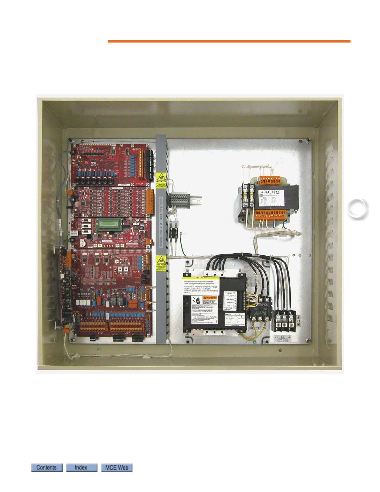
Motion 2000 controllers are ASME A17.1-2000 compliant. A typical Motion 2000 controller is
shown below. Typical board types are called out on the following page.
Car Controller Description
1-3
Page 18
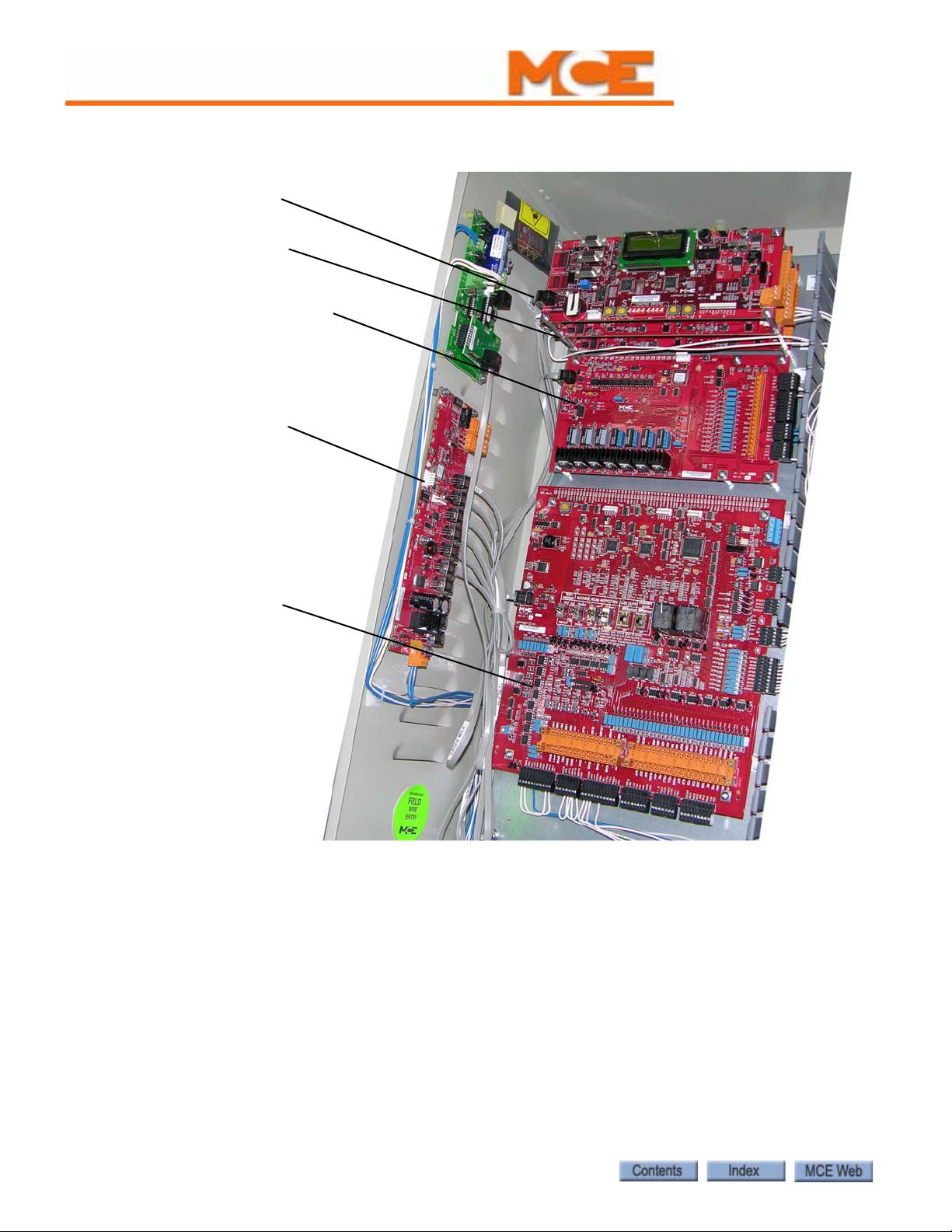
Motion 2000 TSSA Description
HC-DVR Driver Board
HC-CTL-2 Control Board
HC-UIO Universal
Input / Output Board
HC-CHP CAN Hub/
Power Supply
HC-MPU Main
Processor Unit
Figure 1.1 Typical Board Complement (Layout varies)
1-4 Manual # 42-02-1P21
Page 19
1
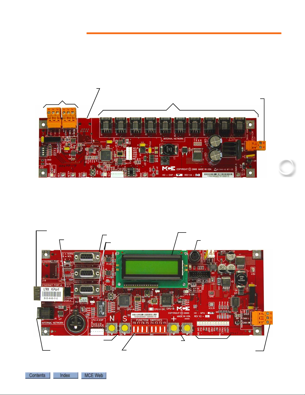
Controller Circuit Boards
16 Vac in
Internal connections
External connections
Optional Ethernet connection
N, S push buttons
Function Switches
F1 through F8
LCD Display
Ethernet Port
Internal CAN connection
CPU B Debug Port
Keyboard Port
External CAN Port
Port Selector
Switch
Indicators
RS232 Ports
+, - push buttons
HC-CHP, CAN Hub and Power Supply: Provides a central connection point for the Controller Area Network (CAN). Also provides 16Vac power for digital integrated circuits throughout the controller. For more information see “HC-CHP CAN Hub and Power Supply
Board” on page 6-38.
Car Controller Description
HC-MPU Main Processor Unit Performs control data processing. The HC-MPU is
responsible for car operation, car communication, programming and diagnostics, redundancy
monitoring, system software validation and duplexing. For more information see “HC-MPU
Main Processor Board” on page 6-50.
1-5
Page 20
Motion 2000 TSSA Description
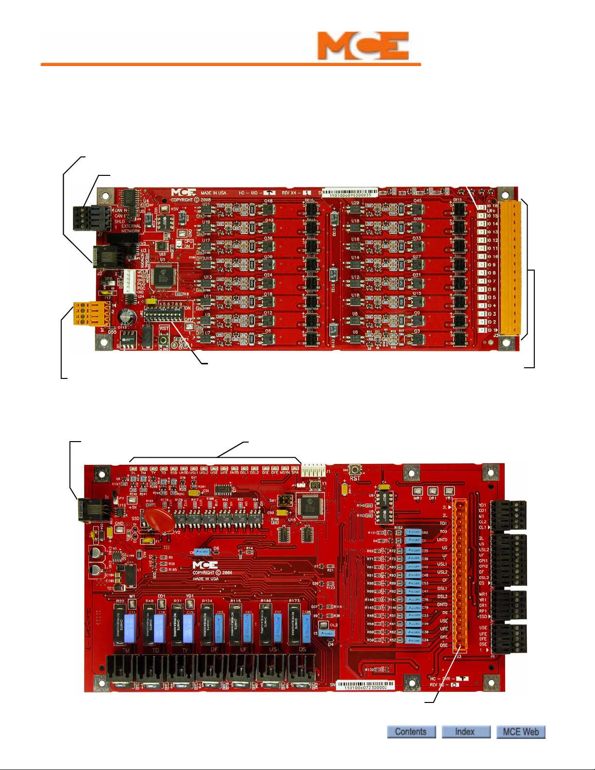
External CAN connection
Internal CAN connection
1 bus and 2 bus
24 - 120V AC or DC Inputs / Outputs
I/O Status Indicators
Board ID
Internal CAN connection
Starter, valve and hoistway limit connections
Indicators
HC-UIO Universal Input/Output Board Depending upon the board configuration, HC-UIO boards may be used for programmable inputs and outputs (16 per board), car and hall calls, and dispatching. In all cases, the functionality of the HC-UIO board can be expanded by “plugging in” additional boards. For more information see “HC-UIO-2 Universal Input/Output
Board” on page 6-53.
HC-DVR Driver Board The HC- DVR Driver board controls the starter and valves. For more information see “HC-DVR Driver Board” on page 6-47.
1-6 Manual # 42-02-1P21
Page 21
1
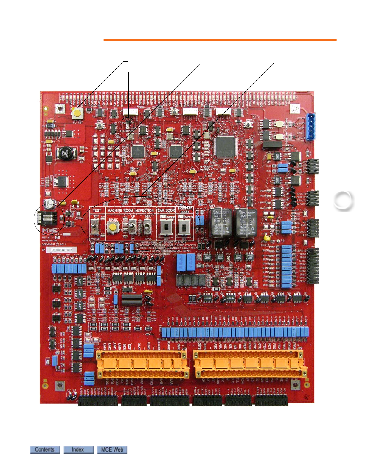
HC-CTL-2 Main Control Board
Machine room
inspection, test,
and door bypass
Fault reset
Internal CAN
connection
Fault bypass
jumper
Car Controller Description
1-7
Page 22

Motion 2000 TSSA Description
HC-CTL-2 Main Control Board Monitors I/O, performs safety functions and front
door operation. Please refer to “HC-CTL-2 Main Control Board” on page 1-7. The HC-CTL-2
board is responsible for inspection, fire service, landing system, door lock bypass and lanterns
and gongs. For more information see “HC-CTL Control Board” on page 6-40.
CE Fixture boards with LON interface (not shown) Used when extensive external fixtures are required.
MC-CPI or ICE-COP-2 Car Panel Interface Board (not shown) Converts the Discrete closures from car panel buttons and switches to CAN data and passes it through the Landing System Interface board (MC-LSI) to the car controller or dispatcher (see “ICE-COP-2
Car Panel Interface Board” on page 6-60).
MC-LSI Landing System Interface Board (not shown) Provides a connection point for the Car Panel Interface board (MC-CPI or ICE-COP-2). A shielded external CAN connection runs from the MC-LSI board, through the traveler, to the Motion 2000 controller (see
“Example: MC-CPI Wiring” on page 6-67).
1-8 Manual # 42-02-1P21
Page 23
1
Landing System
The landing system is designed to be mounted on the car top. Landing systems used with the
Motion 2000 controller include the LS-QUTE, LS-STAN, and LS-EDGE.
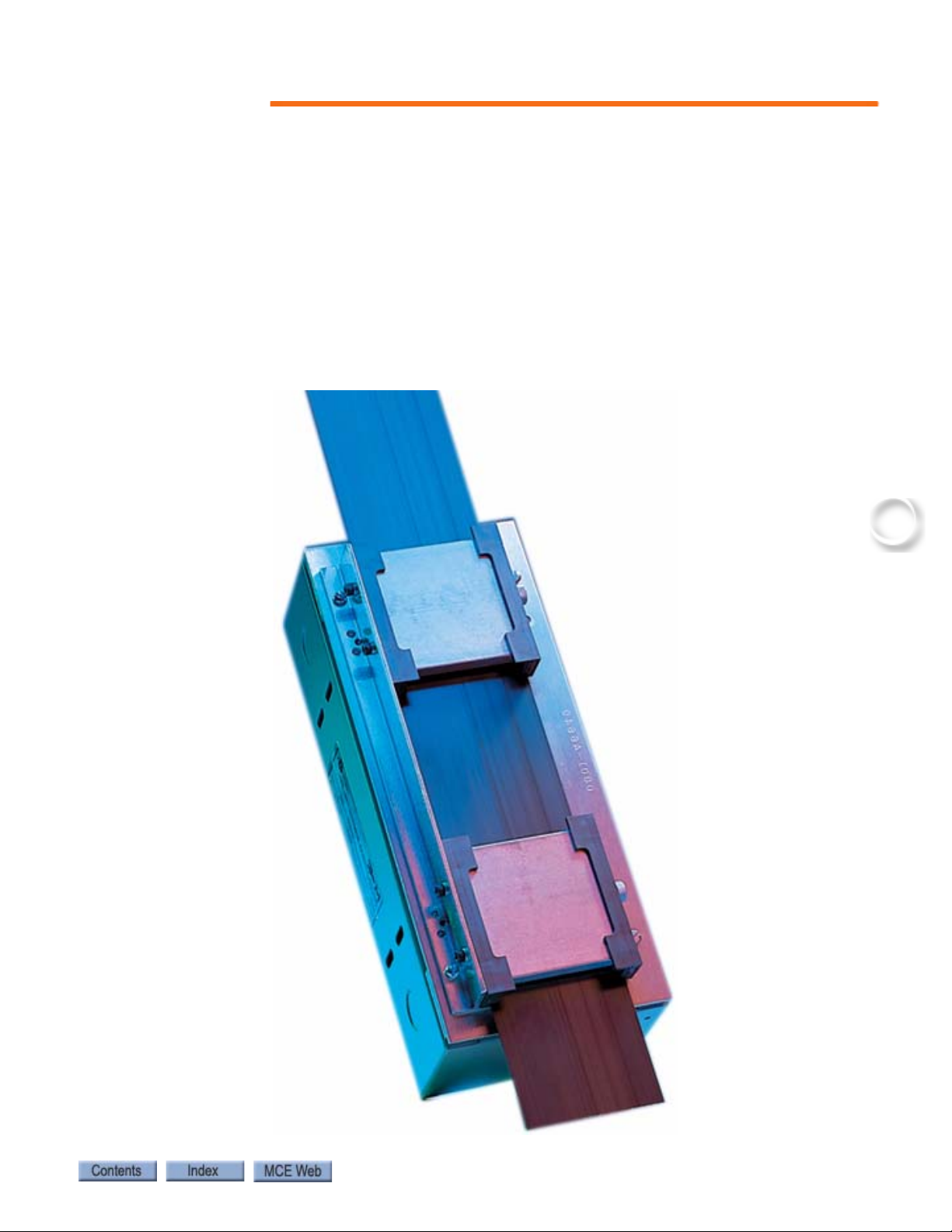
LS-QUTE Landing System
The LS-QUTE is a tape-and-magnet-operated landing system. A three inch wide steel tape is
mounted in the hoistway. The cartop control box has a floating head that slides on the steel
tape, and magnetic sensors for slowdown, STU, STD, ISTU, ISTD, ULM(LU), DLM(LD) and
DZ. With LS-QUTE, the Motion 2000 is configured for absolute floor encoding.
Figure 1.2 LS-QUTE Landing System
Landing System
1-9
Page 24
Motion 2000 TSSA Description
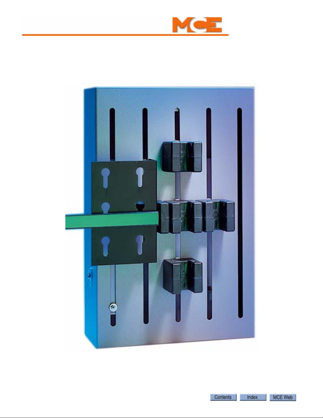
LS-STAN Landing System
The LS-STAN landing system uses VS-1A infrared proximity switches to sense vanes that are
mounted in the hoistway.
Figure 1.3 LS-STAN Landing System
1-10 Manual # 42-02-1P21
Page 25
1
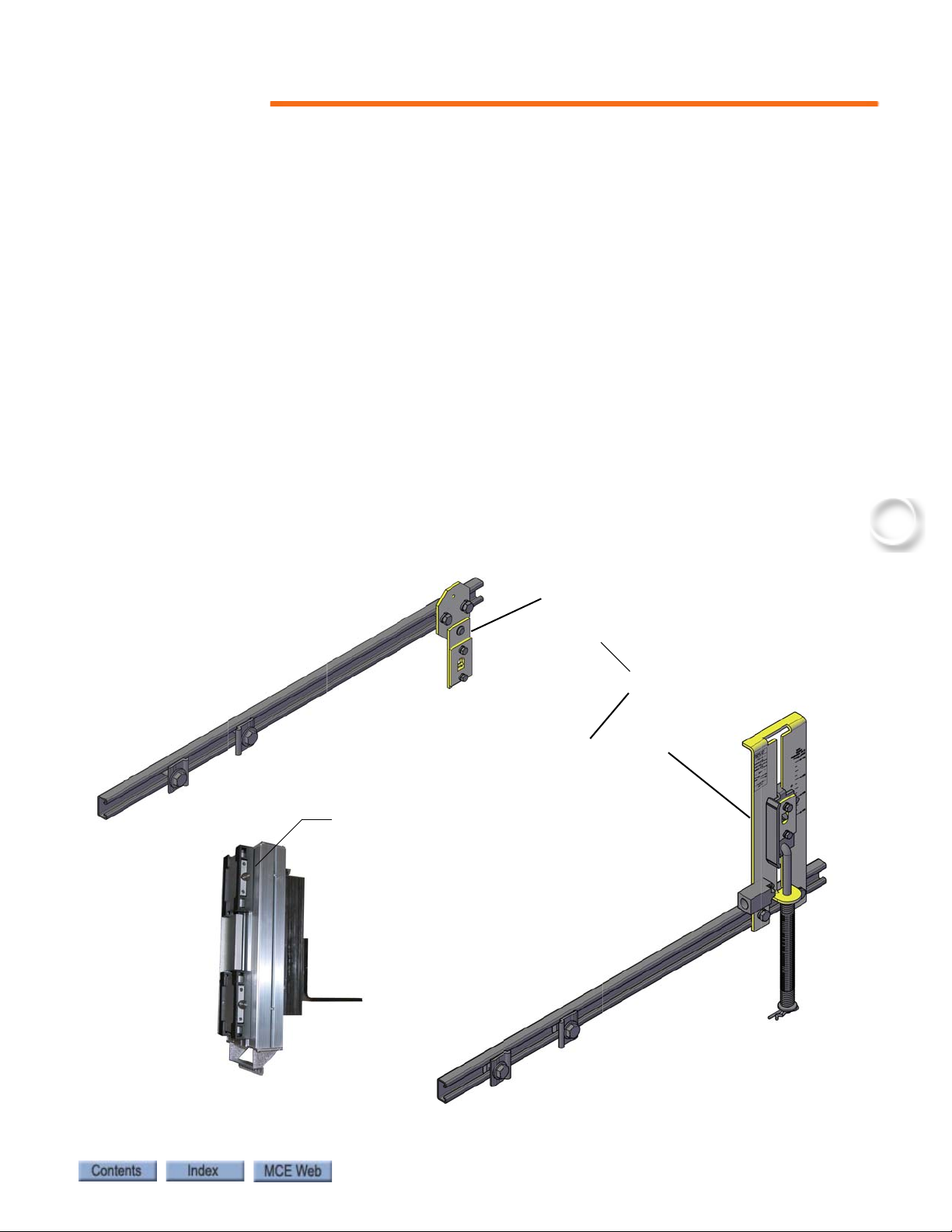
LS-EDGE Landing System
Together, these are assembly
LS-TAPEMNT-EDGE
Steel tape, magnets & connecting cables not shown
Top hanger assembly
(diagonal brace not shown)
LS-TAPEMNTOP-EDGE
Sensor assembly
LS-EDGE
Bottom hanger assembly
LS-TAPE MNTBOT-EDGE
The LS-EDGE positioning system uses hall-effect sensors and perforated steel tape to report
position as the car moves through the hoistway. 5.5-inch magnets are used at each door zone.
The system uses capacitor-stored power and non-volatile memory to retain position information in the event of a power failure, continuing to capture information for 10 seconds after
power loss and storing the final reading for use after power restoration.
The LS-EDGE kit contains the sensor head assembly, an “L” bracket to mount the sensor
assembly to a uni-strut that is in turn attached to the elevator cab (uni-strut to elevator cab not
provided), steel tape, top and bottom steel tape hanger assemblies, the required number of door
zone magnets and terminal magnets, and the CAT-5 electrical cables required to connect the
sensor to the interface board.
Depending on applicable code, you may have to route electrical connections through conduit. If
so, we recommend minimum 3/4-inch flex so that the modular connectors can slide through
without binding. Perforations for cable tie wrap connection are provided on the RJ-45 plug-end
of the sensor head.
LS-EDGE allows most hoistway switches to exist virtually, in software, greatly simplifying
installation and adjustment.
Landing System
Figure 1.4 LS-EDGE Components
1-11
Page 26

Motion 2000 TSSA Description
Operating Mode Descriptions
Available operating modes are configured when the car is installed. Not all modes are available
on all cars. This section describes controller operating modes, including:
• Automatic Operation
• Inspection Operation
• Attendant Service Operation
• Independent Service Operation
• Sabbath Operation
• Emergency Medical Operation
• Hospital Service Operation
• Fire Service Operation
• Emergency Power Operation
•Car Recall
• Capture for Test
•Test Mode
Automatic Operation
Automatic operation is the normal, default elevator operating mode. In this mode, cars are
accepting hall calls and servicing car calls as determined by Basic Features Menu and other
operating menu selections. Please refer to “Basic Feature Menu Options” on page 5-17.
Mode Entry
• Machine Room Inspection Mode Switch: Normal
•Test Switch: Normal
• Car Door Bypass: Off
• Hoistway Door Bypass: Off
1-12 Manual # 42-02-1P21
Page 27

1
Inspection Operation
In inspection, a car operates at the set inspection speed using up and down buttons or momentary switches. The car will stop as soon as the buttons are released. Inspection operation may be
controlled from three locations. For safety purposes, locations have a priority:
• Top of car: When the cartop inspection switch input (INCT on the HC-CTL-2 board) is
active, operation from the controller or from the car panel is disabled.
• In-Car: In car inspection may be from built-in COP switches or from the optional handheld user interface. When the in-car inspection input (INCP on the HC-CTL-2 board) is
active, operation from the controller inspection station is disabled.
• Machine Room Inspection: Inspection operation using the switches in the elevator controller. Available only when cartop and/or in-car inspection is not active.
Cartop Inspection
In this mode, the car is operated by pushing the cartop UP or DOWN and ENABLE buttons
simultaneously. These buttons are generally provided through a third-party inspection station
wired to inspection operation inputs in the elevator controller. There will also be a key switch
that enables/disables inspection operation. In cartop inspection, doors will open (or close) if
both UP and DOWN buttons are pressed for more than two seconds while the car is in a door
zone.
Operating Mode Descriptions
Mode Entry
• Bring the car to the access floor
• Enable hoistway access operation using the in-car switch
• Move the car down until the access limit is opened
• Top access must prevent the car from moving down beyond the point where the crosshead is even with the hoistway entrance sill.
• Set the cartop switch to Inspection before stepping onto the cartop.
• Use ENABLE and UP or DOWN buttons to run the car from the cartop.
In Car Inspection
In this mode, the car is typically operated using a locked sub-panel in the COP that provides the
inspection key switch and direction buttons. Car doors will open (or close) if both UP and
DOWN buttons are pressed for more than two seconds while the car is in a door zone.
Mode Entry
• Bring the car to the desired floor.
• Place the car on in-car inspection.
• Press and hold both UP and DOWN buttons simultaneously to close the elevator doors.
• Use UP or DOWN buttons to run the car.
1-13
Page 28

Motion 2000 TSSA Description
Machine Room Inspection
In this mode, the car is operated using switches on the
HC-CTL-2 (Control) board in the controller.
Mode Entry
• Place the car on Machine Room Inspection
(Mode Switch to INSP).
• Ensure that car and hoistway doors are closed and locked.
• Run the car using the ENABLE and UP or DOWN Directional switch positions.
Hoistway Access Inspection
In the inspection hierarchy, hoistway access operation priority is the same as machine room
inspection (in descending order: cartop, in-car, machine room/hoistway access). Hoistway
access operation allows workers to access the top and bottom of the car from designated floors.
In this mode, the car is brought to an access floor where a special key switch has been installed
that allows a worker to move the car up or down the hoistway.
Mode Entry
• Bring the car to the access floor
• Place the car on Machine Room Inspection
• Place the appropriate Car and Hoistway door bypass switches in the Bypass position
• Enable hoistway access operation using the in-car switch
• Move the car up (bottom access) or down (top access) until the access limit is opened
• Top access must prevent the car from moving down beyond the point where the crosshead is even with the hoistway entrance sill.
• Bottom access must prevent the car from moving up beyond the point where the bottom of the toe guard is even with the hoistway entrance header.
1-14 Manual # 42-02-1P21
Page 29

1
Attendant Service Operation
Attendant operation allows an operator riding in the car to run the car, choosing run direction,
and which hall calls to answer. In this mode:
• Doors open automatically when the car is stopped in a door zone.
• The attendant closes the door by pressing and holding the door close button, a car call button, or either car direction (UP/DOWN) button (UPI/DNI input: Please refer to “Spare
Inputs Menu Options” on page 5-29.
• The attendant chooses the direction using run up (UNI) or down (DNI) buttons.
• The car will stop at the next car or hall call in the direction of travel. Holding the bypass
button (NSI input) in will cause hall calls to be bypassed until the button is released.
• The elevator will level into the destination floor automatically, then open its doors.
• In-car position indicators will light for floors at which there are active hall calls so that
they are visible to the attendant. The car will answer the calls unless the attendant is holding the bypass button (NSI).
• During Attendant operation, load weigher inputs are ignored.
Mode Entry
• Call the car to a floor.
• Enter the car and activate the Att endant mode ke y switch (enabl es the ATS, Atten dant Service, controller input).
Operating Mode Descriptions
Independent Service Operation
In this mode:
• Doors open automatically when the car is stopped in a door zone
• The operator presses and holds the door close button to close doors
• The operator chooses direction and initiates the run by placing car calls (first placed determines direction of run).
• The elevator will level into destination floors automatically and open its doors.
• Hall arrival lanterns or jamb mounted arrival lanterns are inoperative.
Mode Entry
• Call the car to a floor.
• Enter the car and activate the Independent mode key switch (IND input HC-CTL-2 board).
1-15
Page 30

Motion 2000 TSSA Description
Sabbath Operation
Sabbath operation is a special mode that sets the car to consecutively service specified landings
(and openings if the car has front and rear doors) during up and down travel with no hall or car
call buttons being pressed. The car will begin from the bottom of the hoistway, travelling up and
stopping at each designated stop and opening its doors to allow exit or entry. When the doors
close, the car will travel to the next designated stop up the hoistway and repeat door operation.
This will continue until the car reaches the top designated stop, at which point it will travel
down the hoistway operating in the same manner.
• Initiate: Sabbath operation is initiated when the spare input SAB is activated.
• Operation: In accordance with the description above and servicing stops set through the
Sabbath Operation parameter in the Extra Features menu. Please refer to “Extra Features
Menu Options” on page 5-48.
Emergency Medical Operation
This mode complies to Massachusetts code. It allows a car to be recalled to a floor where it can
be boarded by medical personnel and placed in restricted service, using an in-car switch, to
respond to a medical emergency.
• Recall: Initiated using a key switch (EMSH input) at the floor assigned by the Massachusetts EMS Service/EMS Service Floor parameter in the Extra Features menu (single
switch, single floor).
• The car will immediately cancel all registered calls, return to the designated floor, and
open its doors.
• In-Car Medical: Medical personnel board the car and place it in hospital service using the
in-car switch (EMSC input).
• If the hall switch has been shut off, the car will wait sixty seconds then return to normal service if the in-car switch has not been activated.
• If the hall switch remains on, the car will wait without restriction until the in-car
switch is activated.
1-16 Manual # 42-02-1P21
Page 31

1
Hospital Service Operation
Hospital service allows a car to be recalled to any of one or more assigned floors using a call button at the floor. Once at the floor, the car may be boarded by medical personnel and placed in
restricted service, using an in-car switch, to respond to a medical emergency.
• Recall: Floors and openings (if the car has front and rear doors) are designated as hospital
service through Hospital Emerg Operation parameters in the Extra Features Menu. Please
refer to “Extra Features Menu Options” on page 5-48. When a designated call button is
activated, the car will recall to the floor.
• The car will immediately cancel all registered calls, move to the call floor, and open its
doors.
• A Timer Menu function, Hospital Emergency Timer, allows a timer to be set for a
range of up to 10 minutes. After a car recalls to the designated floor, it will remain
there until the timer expires, after which it will return itself to automatic passenger
service if the in-car, hospital service switch has not been activated.
• Operation: Once the in-car switch (HOSP input assigned through the Spare Inputs Menu)
is activated, the car is in restricted service and will accept only calls assigned through the
car operating panel.
• When the in-car switch is deactivated, the car returns to normal service.
Operating Mode Descriptions
Fire Service Operation
There are many different fire codes that restrict or change elevator operation under fire conditions. Please refer to “Fire Service Menu Options ” on page 5-20. In general, fire service pro-
ceeds in two stages; Phase I Emergency Recall and Phase II Emergency In-Car Operation.
When a fire sensor or switch is activated:
• The elevator will recall to the designated main or alternate recall floor. (Main if fire
detected on any floor other than the main floor; Alternate if fire detected on the main
recall floor. Or, as directed by a manually activated Fire switch.)
• The elevator will open its doors to allow any passengers to exit, then remain at the recall
floor until the in-car firefighter switch is activated. Once the in-car switch is activated the
car will run on Fire Phase II operation as allowed by the selected fire code.
1-17
Page 32

Motion 2000 TSSA Description
Emergency Power Operation
Emergency or standby power operation requires a backup power source. For large buildings,
this is typically a diesel or gasoline powered generator. When this is not practical, backup power
for a limited, rescue operation may be provided by a battery-powered system like the Reynolds
& Reynolds Powervator EPS.
Generator Backup
When power is lost, the elevator will come to a full stop. When emergency/backup power comes
on line, the elevator will be moved to a designated recall floor and the doors will open to allow
passengers to exit. The elevator will remain at the recall floor unless it is designated to run
under generator power. Please refer to “Extra Features Menu Options” on page 5-48.
EPS Backup
When power is lost, the elevator will come to a full stop. When battery power becomes available,
the EXMLT input is activated and the elevator will be moved to the bottom floor. At the floor,
the doors will cycle, allowing passengers to exit, and then close. The car will remain out of service until commercial power is again available.
Car Recall
Inputs may be provided to allow the car to be recalled to a specified floor.
• CTF: Car To Floor - This is a “spare” input that may be assigned to the HC-CTL-2 board or
to a Universal I/O board as configured for the job. The floor to which the car is returned is
set by the Car to Floor Return Floor parameter in the Extra Features menu. Please refer to
“Extra Features Menu Options” on page 5-48.
• When activated, causes the car to stop responding to hall calls. Existing car calls will be
serviced. New car calls will not be registered.
• When existing calls have been serviced, the car will move to the return floor, open then
close its doors, and remove itself from service.
• CTL: Car to Lobby - This is a “spare” input that may be assigned to the HC-CTL-2 board or
to a Universal I/O board as configured for the job. The floor to which the car is returned is
set using the Lobby Floor parameter in the Basic Features menu. Please refer to “Basic
Feature Menu Options” on page 5-17.
• When activated, causes the car to stop responding to hall calls. Existing car calls will be
serviced. New car calls will not be registered.
• When existing calls have been serviced, the car will move to the return floor, open then
close its doors, and remove itself from service.
1-18 Manual # 42-02-1P21
Page 33

1
Capture for Test (Pretest)
Pretest is used to capture the car in preparation to using Test mode.
• When this input is activated, the car will stop responding to hall calls and disable its gongs
but continue to service car calls.
• The intent of the input is to allow maintenance personnel to capture the car while causing
as little disruption to service as possible.
• Enter Pretest mode by placing the TEST/NORMAL/PRETEST switch on the HC-CTL-2
board in the PRETEST position. (The car will not enter Pretest if Inspection is active.)
Test Mode
Test mode allows the car to be run without operating the doors. When Test mode is active, door
open circuitry is deactivated.
• Enter Test mode by placing the TEST/NORMAL switch on the HC-CTL-2 board in the
TEST position. (The car will not enter Test mode if Inspection is active.)
• When Test mode is active, the controller LCD will display TEST MODE.
Operating Mode Descriptions
1-19
Page 34

Motion 2000 TSSA Description
Monitoring and Control Options
Motion 2000 is Ethernet ready, allowing it to use iMonitor and iReport applications for local
and/or distance monitoring and control (iMonitor) or report generation, archival, and automated alert (iReport). Motion 2000 can also be linked to Building Management System software through MCE BMS-Link, providing system visibility and limited control.
iMonitor
iMonitor is an elevator monitoring application that allows local or remote viewing and control
of MCE elevator groups using a personal computer running the Windows XP operating system.
Because Motion 2000 controls are Ethernet capable, you can connect to them though a local
area network or remotely through internet/modem technology.
iMonitor provides a graphical representation of elevator groups, allowing their activity and status to be quickly and easily viewed. The user defines any number of “Connection Sets.” Each
Connection Set consists of up to fifty connections to elevator group dispatchers selected by the
user.
When working in iMonitor, the user simply clicks on a Connection Set which automatically
establishes communication with all groups in the set and displays their associated hoistways
and cars on the computer screen. Practical viewing limits are established by the speed of the
connections and the size of the monitor viewing area.
When connected through iMonitor, the user may register car and general, auxiliary, or special
hall calls as desired, control many group security functions, and enable or disable certain elevator operating modes.
iReport
iReport is a system logging and report generating tool that allows local or remote analysis of
MCE elevator groups from a personal computer running the Windows XP operating system and
iReport client software. Because Motion 2000 controls are Ethernet capable, you can use iReport to connect to them through a local area network or remotely through internet/modem
technology.
iReport consists of the iReport server and iReport clients. Motion 2000 group dispatchers may
be connected to iReport directly through a local area network or they may be connected
remotely through a DSL or other high-speed connection and the internet. The group dispatch er
provides iReport with hall call and car operating mode information. The individual car controllers provide iReport with event and fault notifications.
1-20 Manual # 42-02-1P21
Page 35

1
BMS-Link
Internet
Utility Company
Building Automation
Heating/Cooling Plant Lighting
Intelligence Intelligence
BMS-LINK
Elevator Controllers
BMS-LINK uses the Niagara Framework developed by Tridium. The framework is a fieldproven Java implementation that provides a reliable structure through which intelligent equipment may connect in a machine-to-machine environment. Motion Control Engineering and
Gemini Integration Systems developed the software structure that integrates MCE iControl,
Motion 2000, and Motion 4000 elevator controls and Motion 3000 escalator controls into this
robust environment.
Monitoring and Control Options
Motion Portable Adjustment Control (mPAC)
The hand-held user interface provides the same user functionality as does the HC-MPU board inside the controller.
The mPAC can be plugged in to a CAN connection in the controller, on the cartop, or in the car (if one is wired). In addition, the mPAC can be used to transfer new firmware to
Motion 2000 and Motion 4000 controllers.
1-21
Page 36

Motion 2000 TSSA Description
mView
The mView application runs on a standard PC connected to the controller through an Ethernet
hub or switch. mView provides local monitoring, status and event log viewing, diagnostics, and
call registration for one or more Motion controllers.
1-22 Manual # 42-02-1P21
Page 37

2
Installation
• In this Section
• Safety Precautions
• Machine Room Preparation
• Piping and Wiring
• Recommended Tools
• Wiring Prints
• Controller Installation
• General Wiring Guidelines
In this Section
This section contains important recommendations and instructions for installing the Motion
2000 Hydraulic controller. If you are viewing this on a computer, click the page number to
jump to the appropriate section.
• Safety Precautions: Precautions for personal and equipment safety (see page 2-2).
• Machine Room Preparation: Site selection and environmental considerations (see
page 2-3).
• Piping and Wiring: Suggestions for avoiding electrical noise and EMI/RFI (see page 2-4).
• Recommended Tools: Tools and test equipment recommended for installation (see
page 2-5).
• Wiring Prints: Job print and nomenclature conventions (see page 2-5).
• Controller Installation: Suggestions for proper controller wiring (see page 2-7).
• General Wiring Guidelines: Suggestions for proper grounding and wiring (see page 2-8).
2-1
Page 38

Installation
Safety Precautions
Certain fundamental warnings must be kept in mind at all times to help avoid severe personal
injury or equipment damage.
Personal Safety
• Motion 2000 Controllers should only be installed by qualified, licensed, trained elevator
personnel familiar with the operation of microprocessor-based elevator controls.
• Verify that all safety devices (limits, hoistway locks, car gate, etc.) are fully functional
before attempting to run the elevator. Never operate Motion 2000 controls with any safety
device inoperative.
• The user is responsible for complying with the current National Electrical Code with
respect to the overall installation of equipment and for proper sizing of electrical conductors connected to the controls.
• The user is responsible for understanding and applying all current local, state, provincial,
and federal codes that govern practices such as controller placement, applicability, wiring
protection, disconnections, over current protection, and grounding procedures.
• Controller equipment is at line voltage when AC power is connected.
• After AC power has been removed, internal capacitors can remain charged for up to 5 minutes. Wait at least 5 minutes after power down before touching any internal components.
• To prevent the risk of shock, all equipment should be securely grounded to earth ground
with a minimum of #8 AWG wire as outlined in the National Electrical Code. Failure to
obtain an actual earth ground may result in electrical shock to personnel and/or improper
operation of the equipment.
• When using test equipment (oscilloscopes, etc.) with a power cord that electrically ties
probe common to earth ground, an isolation transformer should be used to isolate the
instrument common from earth ground.
• Remain clear of all rotating equipment while working on the controls.
Equipment Safety
• All equipment should be securely grounded to earth ground with a minimum of #8 AWG
wire as outlined in the National Electrical Code. Failure to obtain a true earth ground may
result in electrical shock. Improper grounding is the most common cause of electrical
component failure and noise-induced problems.
• Replace components only with main line power off. Damage to equipment or unexpected
operation of the elevator may occur if this precaution is not observed.
• Substitution of parts or unauthorized modifications should not be attempted before first
contacting Motion Control Engineering to ensure all safety features are maintained. MCE
will not be held responsible for circuit modifications made in the field unless they are
approved in writing by MCE.
• Circuit boards believed to be defective must be sent to MCE for repair and testing. Field
repair may leave the board with undetected problems.
• Care should be taken when using test leads and jumpers to avoid shorting high voltage or
ground to low voltage microprocessor circuits.
2-2 Manual # 42-02-1P21
Page 39

2
Installation Considerations
1. Dust, carbon, or metallic particles should not be allowed to accumulate on any part of the control.
2. Avoid vibration and shock.
3. Avoid rapid temperature change, high humidities, high ambient temperatures.
4. Avoid caustic fumes.
5. Prevent electromagnetic interference. This may be caused by radio transmitters, high voltage inductive spikes from unsuppressed relay coils, improper grounding, and improper wiring practices. The following should be noted:
• The outer door will protect against interference only if closed. When the door is open,
do not run high wattage radios next to the microprocessor.
• Noise from door operator reactors can cause a problem if mounted on the controller.
• Standard arc suppressors (resistor/capacitor networks) are used on AC relays. Diode/
resistor combinations work well for DC relays. Consult Motion Control Engineering for
proper component sizing.
Machine Room Preparation
Installation Considerations
When choosing equipment location, consider:
• Adequate working space for comfort and efficiency and a good working space such as a
workbench or table.
• Logical arrangement, taking into consideration other equipment in the machine room and
electrical power.
• Do not install equipment in a hazardous location.
• A telephone in the machine room facilitates remote diagnostic and adjustment assistance.
• If any areas in the machine room are subject to vibration, they should be avoided or reinforced to prevent equipment damage.
• Provide adequate lighting to work with control cabinets and machines.
• Wiring is reduced if the drive isolation transformer (if used) is located near the controller.
Environmental conditions are important:
• Ambient temperature should remain within 32
Temperatures outside these guidelines may be tolerated, but will shorten equipment life.
Adequate ventilation is required. Air conditioning may be necessary.
• The air in the machine room should be free of excessive dust, corrosive elements, and
excessive moisture. A NEMA 4 or NEMA 12 enclosure can help meet these requirements if
machine room conditions are inadequate. If the machine room has open or unglazed windows or other direct outside openings, place equipment cabinets far enough from them so
that severe weather does not damage the equipment.
• Very high levels of radio frequency (RF) radiation from nearby sources should be avoided.
RFI may interfere with controller components, degrading elevator performance. Using
hand-held communication devices close to the controller may also cause interference.
Interference from permanently installed radio transmitting antennas is not common.
• Power line fluctuation should not be greater than ±10%.
to 104 Fahrenheit (0 to 40 Celsius).
2-3
Page 40

Installation
Piping and Wiring
Proper routing of signal and power wires for the car and dispatcher is essen tial to trouble free
installation of microprocessor based equipment. Low voltage and high voltage wiring cannot be
run in the same conduit, duct, or tray.
How Electrical Noise Occurs
Electrical noise occurs in most cases when two wires run along side one another with one of
them a high power conductor and the other a low signal level conductor. As current flows
through the high power wire, magnetic lines of flux (voltage) expand outwards around the outside of the wire and voltage from the magnetic lines of flux is induced in the low level conductor.
The low level conductor, in the case of Motion 2000, may be a 24-volt input that really only
needs to see 12 volts to turn on. If the voltage induced from the high power conductor is large
enough to induce a 12-volt spike, the input can falsely turn on.
How to Avoid Electrical Noise Problems
The easiest way to avoid noise problems is to properly route high and low level signal wiring.
Keep low level wiring in separate conduit from high power wiring. If high and low power wiring
must be run in the same duct, separate them by a minimum of three to four inches. If one must
cross the other, it should be at a ninety degree angle.
A second way to protect against electrical noise problems is to run low level wiring in shielded
cable. The shield provides a conductor external to the actual signal wiring to collect any induced
voltage from surrounding high power wiring. The shield or “drain”, as it is often referred to,
must be connected to ground at one end. The shield or “drain” should never be connected to
ground at both ends.
Possible EMI/RFI Interference
The main source of EMI/RFI problems is semiconductor devices that switch at high frequencies
(such as variable frequency drives). The following wiring practices should be followed when
piping and wiring high voltage lines to avoid EMI problems:
1. Run all motor leads in a separate conduit. All motor lead runs should be as short as possible. Control cabinet entry should be as close to the final termination point as possible.
2. Run main line supply leads in a separate conduit.
3. Run all primary isolation transformer wiring in separate conduit from the main line to the transformer.
4. Run all secondary isolation transformer wiring in a separate conduit from the transformer to the drive cabinet.
5. A single-point ground should be established inside the control cabinet and a #8 AWG ground wire run directly from each of the following devices to this single point:
• Earth Ground from running water supply, Motion 2000-electric supplied ground, or a
ground supplied via an earthing rod to the single ground stud.
• Continuous wire from the main line disconnect to the single ground stud.
• Continuous wire from the motor frame to the single ground stud.
• Continuous wire from the isolation transformer frame to the single ground stud.
• Continuous wire from the line filter frame to the single-point ground stud.
2-4 Manual # 42-02-1P21
Page 41

2
• Jumper the “N” stud on the line filter to the line filter frame.
Note
• Continuous wire from the load reactor frame to the single-point ground stud.
• Continuous wire from the drive frame ground stud to the single-point ground stud.
Recommended Tools and Test Equipment
For proper installation, use the following tools and test equipment:
• A digital multimeter, Fluke series 75, 76, 77 or equivalent
• A hand-held tachometer
•A clamp-on AC ammeter
• Hand-held radios
•A telephone
•Test weights
• Pressure gauge
• Soldering tools, a flashlight and an MCE screwdriver (provided with controller).
Wiring Prints
Become familiar with the following information as well as the wiring prints provided with this
control system.
Installation Considerations
Drawing Number Format
Each print has a drawing number indicated in the title block. The drawing number is comprised of the job number, car number and page number (see example). In this manual the drawings will often be referred to by the last digit of the drawing number (page number). The
following is the drawing number format currently in use.
Drawing Name: Some drawings have a drawing name directly above the title block or at the
top of the drawing. The drawing name may be used to refer to a particular drawing.
2-5
Page 42

Installation
Nomenclature
A listing of PC boards and their designator numbers plus other schematic symbols used in the
wiring prints can be found at the beginning of the Job Prints and in the Component Nomenclature table below.
• Become familiar with the “Elevator Car Wiring Print” drawing number -1.
• Become familiar with the “Elevator Hoistway Wiring Print” drawing number -2.
• Become familiar with page -2DI of the job prints for duplex interconnect wiring if this
application is duplexed.
• Review any additional wiring diagrams and details.
• The remainder of the job prints are detailed drawings of the Motion 2000 Hydraulic Control system.
• A specific part of a schematic may be referenced by the Area Number, which is found at the
left-hand margin of the schematic.
The following table lists MCE part numbers and provides a brief description for each. Your
installation may not use all boards listed.
Table 2.1 Component Nomenclature
Symbol Component Description
10 HC-DB-MOD Front G. A. L. MOD Door Interface Board
11 HC-DB-MOD-R Rear G. A. L. MOD Door Interface Board
32 HC-OA Output Adaptor Board
44 HC-GB Gong Board
45 HC-GB Additional Gong Board
70 HC-CTL-2 Controller Board for Motion 2000/4000
72 HC-DVR Hydraulic Driver board for Motion 2000
73 HC-UIO Universal I/O Board for Motion 2000/4000
75 HC-CHP CAN HUB and Power Board for Motion 2000/4000
76 HC-MPU Main Processor Board for Motion 2000/4000
ICE-COP-2 Car panel interface board
MC-CPI Car Panel Interface Board
MC-LSI Landing System Interface Board
SC-3HN Serial Hall Call Node Board
2-6 Manual # 42-02-1P21
Page 43

2
Controller Installation
Caution
Note
Caution
Mount the controller securely to the machine room wall or other appropriate location and
knock out holes to install a raceway or conduit to permit the routing of wires into the cabinet.
Note that the standard MCE control cabinet does not require rear access.
Do not allow any metal chips or drill shavings to fall into the electronics.
Controller Wiring Guidelines
Detailed instructions for connecting the Motion 2000 controller and accompanying components are contained in the drawings package for the job. During the job survey, site-specific
information collected is used to engineer the drawings package. Contact Motion Control Engineering immediately if you have questions about the drawings or need additional assistance.
Controller Installation
Pay very close attention to the hierarchy of the inspection inputs. In order to maintain safe
operation of the lift while on access, car top or in-car inspection, the inspection circuits must be
wired as shown in the prints.
PC boards can be easily damaged by Electrostatic Discharge (ESD). Use a properly
grounded wrist strap when touching the PC boards. Do not touch PC Boards unless
you are properly grounded
1. Bring wires in from a location that allows the use of the wiring duct inside the controller to route the wires. The terminals are found conveniently near wiring ducts.
2. When connecting wires to the controller, connect the wires according to the hoistway and car wiring diagrams.
3. If the car is part of a duplex or group system, there are a number of details relating to the wiring of the interconnects between the individual cars. They are as follows:
• A separate conduit or wiring trough must be provided for the external CAN connections between the computers in each controller cabinet.
• The wiring details for the communication link are fully detailed in the job prints.
• Make sure to ground all of the cabinets according to the section titled Ground Wiring.
Please refer to “Ground Wiring ” on page 2-9.
.
2-7
Page 44

Installation
General Wiring Guidelines
Basic wiring practices and grounding requirements are discussed in this section.
Proper Grounding Procedures
A proper ground is essential to trouble free operation. Ground is defined as a direct connection
to EARTH GROUND. This type of ground is not always available from the electrical supply
panel.
The electrical conduit is not a sufficient ground for the system. Electrical ground should be
obtained and certified from the electrical contractor. If this is not available, keep the following
in mind when seeking an adequate connection to EARTH GROUND:
1. Building steel is not always earth ground. In most cases, building beams rest on concrete beam pockets, and the earth connection is inadequate.
2. Sprinkler system water pipe is not
cases, isolated from a free flowing earth water source.
If either of the two methods above are chosen for ground, and a true electrical ground is later
introduced to the system, a difference in potential can occur between the assumed ground and
the actual earth ground. This may lead to unsafe operating conditions and the possibility of
electrical shock to passengers or personnel.
adequate because the sprinkler system is, in most
3. A water pipe is an adequate ground only if the water in the pipe is connected to a continuous city water source.
Wiring Connections for Properly Grounded Systems
1. An uninterrupted ground wire of at least #8 AWG should be run from each car controller cabinet chassis or back plate to earth ground. The connection at the car controller
must be free of paint so the ground connection is made to the bare metal of the enclosure. The car controller should read less than 1-ohm to ground with the power off.
2. Ground straps, or short loops of ground wire, should be run from the controller ground connection to the primary duct connections.
3. An uninterrupted #8 AWG ground wire should be run from the hoist motor frame to the controller ground. The ground connection to the hoist motor must be free of paint.
4. An uninterrupted ground wire of minimum #14 AWG should be run from a termination point on the cab to the controller ground.
5. An uninterrupted ground wire should be run from the cab enclosure to the ground terminal on the cab to protect passengers and personnel from electrical shock.
6. An uninterrupted ground wire should be run from each car operating panel to the ground terminal on the cab to protect passengers and personnel from electrical shock.
7. An uninterrupted ground wire should be run from the dispatch cabinet chassis or back plate to earth ground. The connection at the dispatch cabinet must be free of paint so the ground connection is made to the bare metal of the enclosure.
2-8 Manual # 42-02-1P21
Page 45

2
Ground Wiring
To obtain proper grounding, quality wiring materials and methods should be used.
All grounding in the elevator system must conform to all applicable codes. Proper grounding is
essential for system safety and helps to reduce noise-induced problems. The following are some
grounding guidelines:
• The grounding wire to the equipment cabinet should be as large as, or larger than, the primary AC power feeders for the controller and should be as short as possible.
• The grounding between equipment cabinets may be branching or a daisy chain, but the
wire must terminate at the last controller and NOT loop back (see Figure 2.1).
Figure 2.1 Ground Wiring to Controller Cabinets
General Wiring Guidelines
• Direct solid grounding must be provided in the machine room to properly ground the controller and the motor. Indirect grounding, such as the building structure or a water pipe,
may not provide proper grounding and could act as an antenna radiating RFI noise, thus,
disturbing sensitive equipment in the building. Improper grounding may also render an
RFI filter ineffective.
• The conduit containing the AC power feeders must not be used for grounding.
Main AC Power
Main AC power supply wiring size must be determined by the electrical contractor. Proper
motor branch circuit protection must be provided according to applicable electrical codes in the
form of a fused disconnect or circuit breaker. Each disconnect or breaker must be clearly
labeled with the elevator number.
Pump Motor Wiring
Connect the pump motor for the proper configuration shown on the wiring diagrams. Connect
the pump motor leads to the proper terminals on the controller.
2-9
Page 46

Installation
Low Voltage Signal Wiring
Low voltage signal wiring includes all 24-volt inputs. The inputs on the I/O boards can be
turned on with as little as 12 Vac. If the signal wires are run along side the 240 Vdc door operator wiring, an induced 12-volt spike is very likely to occur. Keep low level signal wiring at least
four inches from high power wiring to avoid false signal firing. If this is not possible, and the
low level wiring must cross the high power wiring, the two should cross at a ninety-degree
angle.
Traveling Cable Wiring
When laying out traveling cable wiring, it is always best to have the low voltage signal wiring
multiple layers away from any 14-18 AWG power wires and high voltage signal wires.
The number of required wires and twisted pairs is documented in the job prints. The travelers
are also identified by the use of yellow te rminals in the top of the car j unction bo x. Always al low
10% or more additional wires for spares.
On lower rise cars, it is often beneficial to run the traveling cable directly to the top of the car
junction box. This avoids terminating traveler wires at the midway and at the under-car junction box.
2-10 Manual # 42-02-1P21
Page 47

3
• In this Section
• Check for Shorts to Ground
•Before Applying Power
• Applying Power
• Operating under Construction
• Verifying Starter Operation
• Install the Landing System
•Hoistway Limit Switches
• Door Position Monitor
• Complete Field Wiring
• Preparing to Run on Test
Startup - Inspection Operation
In this Section
This section discusses preparing the car to run on Inspection operation. It covers the sequence
of applying power to the controller and verifying proper motor rotation. It also covers completing the installation of hoistway equipment, initial adjustment of the system and preparing the
car for normal operation and final adjustment.
• Check for Shorts to Ground: How to check for shorts to ground (see page 3-2).
• Before Applying Power: Things to do before applying power (see page 3-2).
• Applying Power: Steps to apply power and check for proper pump motor rotation (see
page 3-3).
• Set Up for Construction Operation: Minimum requirements to allow the car to run
while still under construction (see page 3-4).
• Verifying Proper Starter Operation: How to verify proper starter operation (see
page 3-7).
• Installing the Landing System: Instructions for installing the landing system (see
page 3-9).
• Installing the Hoistway Limit Switches (LS-QUTE): How to install the hoistway
limit switches (see page 3-10).
• Door Position Monitor Switch: Installing the door position monitor switch, if used.
(see page 3-22).
• Complete the Installation and Field Wiring: Finish the installation and wiring and
check for shorts (see page 3-22).
• Preparing the Car to Run on Test/Normal Mode: How to prepare the car for running on automatic operation (see page 3-22).
3-1
Page 48

Startup - Inspection Operation
Note
Note
Check for Shorts to Ground
Check for shorts to ground before powering up the system. Set the meter for resistance measurement (100 to 200 ohm range). Take all measurements with respect to the 1 -bus, which is
also referred to as the system common or common elsewhere in this manual.
A short to ground is defined as having a resistance of less than 20 ohms between the 1-bus
(common) and the terminal being checked.
1. Remove fuse F2 from the fuse holder in the individual car controller cabinet. If the system is a duplex controller, refer to the job prints and remove the fuse that powers terminals 2H (Hall Call Power Bus) and/or 2FS (Fire Service Bus). Check for shorts to ground
on the 2H and/or 2FS terminals.
2. Check for shorts to the ground on all screw terminals on the bottom of the HC-CTL-2 Control board. Terminal 1 bus is the only terminal that should be grounded.
3. Check for shorts to ground on all terminals on the HC-UIO Universal I/O board.
4. Check for shorts to ground on the door operator terminals. Consult the job prints to determine which fuses to remove.
Before Applying Power
These instructions assume adequate electrical troubleshooting experience. Follow the procedure carefully. If the elevator does not respond correctly, check the circuits according to your
ability. Proceed cautiously. Read these instructions fully to become familiar with the procedure
before starting the work.
1. Unplug the screw terminal blocks from the HC-UIO Universal I/O boards by moving the
blocks toward the right. This is done to avoid damaging the boards through an accidental shorting of the output devices to a power buses (terminals 2, 2S, or 2L) during the
initial power up of the system.
2. Verify that all circuits are wired to the controller properly.
3. On the HC-CTL-2 Control board, verify that the MACHINE ROOM INSPECTION MODE switch is in the INSP position.
4. On the HC-CTL-2 Control board, verify that the Hoistway Door and Car Door Bypass switches are in the OFF position.
5. Verify that the Main Line Power Supply voltage matches the controller’s designed voltage. Refer to the job prints provided with the controller and the silver label on the solid
state starter (if used).
3-2 Manual # 42-02-1P21
Page 49

3
Applying Power
Note
Initial Adjustments and Power Phasing
When performing the following steps please exercise extreme caution to prevent personal
injury or damage to components and equipment. Have someone stand by the main power disconnect switch during the following phases of the start up procedure for added safety:
• First time power is applied to the controller
• First time an attempt is made to move the car
1. Check the line side of the Main Power Disconnect switch to verify that all three legs are at the correct voltage.
2. Reinstall fuse F2 to enable the primary controller relay voltage.
Verify Proper Pump Motor Rotation
1. Verify that the pump motor wiring has been installed per the job prints.
2. Turn ON power to the controller by closing the Main Power Disconnect switch.
3. Check the pump motor rotation using the method that is appropriate for the type of starter installed on the controller:
• Solid State Starter: Take a jumper from 2 bus and briefly apply it to the “motor run”
screw terminal on the solid state starter and observe the motor rotation.
• Y-Delta contactor: Activate the Y contactor and observe motor rotation.
• Across the line (ATL) contactor: Activate the A contactor and observe motor rota-
tion.
4. Faults may occur while performing this operation. To clear latching faults, place the car
on Machine Room Inspection and press the FAULT RESET button on the HC-CTL Control board.
5. If the motor rotation is reversed, switch any two of the three leads at the Main Disconnect switch.
6. If an RP (Reverse Phase) sensor is provided and the sensor contact does not close when
power is applied to the controller (indicated by a light on the sensor that comes on when
phase rotation is correct), then 2 of the 3 AC wires that are connected to the RP sensor
may need to be switched.
7. To provide an immediate stop once direction is released, set the SOFT STOP TIMER
option on the ASME A17.1-2000 FEATURES menu to NONE (see “SOFT-STOP TIMER”
on page 5-54).
Applying Power
The HIGH SPEED INSPECTION option determines if the car will run at high or low speed on
In-car, Cartop, or Machine Room Inspection or Hoistway Access (see “HIGH SPEED INSPEC-
TION” on page 5-66. If the car contract speed is greater than 150 fpm, the HIGH SPEED
INSPECTION option should be set to DISABLED.
3-3
Page 50

Startup - Inspection Operation
If rear doors:
• 2 - GSR
• 2 - DLABR
• 2 - DPMR (Spare input, UIO or CTL-2 - see prints)
To run on Machine Room Inspection:
• Jumper INCT to 2 Bus
HC-CTL-2 Board
HC-DVR Board
FRS
INN
DLAB
GS
FRSA
FRSM
SAFH
SAFC
ESC
GSR
DLABR
2
2
2FS
TO2
UNTD
USL1
USL2
DSL1
DSL2
DNTD
TO1
2L
DPM
Set Up for Construction Operation
If required, it is possible to run the car during construction to help complete work in the hoistway. In this mode, the car runs at inspection speed. If they are in place, cartop controls may be
used or the car may be run from the controller or a temporary run box. (Please refer to “Tempo-
rary Run Box Hookup” on page 3-6.)
Required Connections
Please refer to “Construction Mode Jumper Requirements” on page 3-5 and to the following
illustration and text.
Figure 3.1 Jumpers Used Before Final Equipment Connected
Minimal equipment requirements are:
•Pump motor and valves.
• SAFH, SAFC, ESC: Hoistway and car safety devices. Connecting 2 bus to these terminals
(as described in Table 3.1) will cause relay SAFS on the HC-CTL-2 board to pick and light
the SAFS indicator (provided no safety-dropping faults are present).
• GS, DLAB: Door locks. (GSR, DLABR: Rear door logic and door locks.) Connecting 2 bus
to these terminals will cause relay SAFL on the HC-CTL-2 board to pick and light the SAFL
indicator (when direction has been established). The DLK indicator on the HC-MPU board
will turn ON (provided that no safety-dropping faults are present).
• TO2: Thermal overload protection. Connecting TO1 to TO2, as specified on the job prints,
will clear the OLM INPUT IS LOW fault (Overload monitor). When this fault is present the
car can only move down.
3-4 Manual # 42-02-1P21
Page 51

Set Up for Construction Operation
3
• DNTD, UNTD: Up and down terminal limit switches. Connecting 2L bus to these terminals clears the faults caused by the final limit terminals being open.
• USL1, USL2, DSL1, DSL2: Slow down limits. Connecting 2L bus to these terminals clears
the faults caused by having both sets of slow down terminals open.
• Custom Connections: Custom spare input connections that are active low and affect car
motion, such as the Pressure Switch and Low Oil Switch, must be installed.
Temporary Jumpers
Temporary jumpers, as necessary, may be connected if needed to run the car on construction /
inspection operation. For Temporary Run Box connections see page 3-6.
Table 3.1 Construction Mode Jumper Requirements
From To
2 bus SAFH on HC-CTL-2 board (Safety String, Hoistway)
SAFH on HC-CTL SAFC on HC-CTL-2 board (Safety String, Car)
SAFC on HC-CTL ESC on HC-CTL-2 board (In-car Emergency Switch)
2 bus (120VAC) GS on HC-CTL-2 board (Gate Switch, car door locks)
2 bus (120VAC) INN on HC-CTL-2 board
2 bus (120VAC) GSR on HC-CTL-2 board (Rear Gate Switch, car door locks)
2 bus (120VAC) DLAB on HC-CTL-2 board (Door Lock Access Bottom, hall doors)
2 bus (120VAC) DLABR on HC-CTL-2 board (Rear Door Lock Access Bottom, hall doors)
2 bus (120VAC) DPM on HC-CTL-2 board or HC-UIO board (Door Position Monitor)
2 bus (120VAC) DPMR on HC-CTL-2 board or HC-UIO board (Door Position Monitor Rear)
TO1 on HC-DVR TO2 on HC-DVR board or install thermal overload as specified on job prints
2L bus (120VAC) DNTD and UNTD on HC-DVR board (Normal Terminal inputs)
2L bus (120VAC) USL1, USL2, DSL1, DSL2 (Slow down limits) to clear faults. Must be installed to run the
high speed valves while on Construction Mode. However. if the car’s contract speed is
greater than 150fpm, set HIGH SPEED INSPECTION option to DISABLED (see page 5-66).
2FS bus
(120VAC)
FRS, FRSA, and FRSM on HC-CTL-2 board (Fire Service inputs) only required to clear
faults. Car will run on Inspection without the jumpers.
Resolving Faults
If the car does not respond to a run command, check the HC-MPU board for error/fault codes.
Please refer to “Status and Error Messages” on page 6-3. Error codes are displayed individually
in the order of detection. It is possible that, after you correct a current error condition, another
will be displayed. All errors must be resolved before the car will operate properly.
3-5
Page 52

Startup - Inspection Operation
Caution
ICTU
ICTD
CTEN
INCT
2
Machine Room
HC-CTL-2 Board
Traveler
Car
Temporary Run Box
PMT Strip
ENABLE
UP DOWN
NORM
INSP
Temporary Run Box Hookup
The following illustration shows a temporary run box hookup. Disconnect controller power
before attempting to wire the run box. The temporary run box must have an enable button, an
up button, a down button, and a stop (Insp/Norm) switch (see Figure 3.1).
For safety, keep the controller Machine Room Inspection switch in the INSP position while
the Temporary Run Box is in use.
Caution 2
If a jumper was installed between HC-CTL-2 board terminals SAFH and SAFC as described
in Table 3.1 Construction Mode Jumper Requirements, that jumper must be removed
when a temporary run box is connected (see Figure 3.1).
Figure 3.2 Temporary Run Box
3-6 Manual # 42-02-1P21
Page 53

Verifying Proper Starter Operation
3
Verifying Proper Starter Operation
1. Verify that any fuses removed during the ground check have been reinstalled. If not,
turn power OFF at the Main Power Disconnect switch, reinstall the fuses and then turn
power back ON. Verify that the Machine Room Inspection Mode switch on HC-CTL-2
board is in the INSP position.
2. When power is turned ON, the LCD display on the HC-MPU Main Processor board will
display the message
TROL M-2000
present, will scroll the error message instead. If there is an error condition, it must be
addressed or bypassed with a temporary jumper (see “Troubleshooting Tools” on
page 6-2).
3. LEDs SAF ON, DLK, and INSP should be ON and relays SAFL and SAFS should pick as
indicated by the SAFL and SAFS LEDs. Use the MACHINE ROOM INSPECTION
switches on the HC-CTL-2 Control board to move the car up or down. Press and hold the
ENABLE button and then hold the DIR switch in the UP or DN position.
4. Follow the appropriate instruction below for the type of starter (solid state, Y-Delta or ATL) installed on the controller.
Solid State Starter The Solid State starter will control the starting current to the motor (see the Solid State starter manual). Adjust the UP TO SPEED TIMER option, see “UP TO
SPEED TIMER” on page 5-54) to provide a sufficient delay for the pump motor to get up to
speed. Once the pump is at speed, the valves will be activated. If the motor does not spin when a
demand up is present:
, and then change to MACHINE ROOM INSPECTION or, if an error condition is
MOTION CONTROL ENGINEERING, INC, then change to MOTION CON-
• Verify that there are no faults displayed on the HC-MPU board LCD display or the solid
state starter display.
• Verify that relays SAFS and SAFL are picked (with Direction applied).
• If neither relay is picked, check fuse F2 and then verify that the voltage measured
between terminals 1 (1Bus) and 2 (2 Bus) is 120 VAC.
• If relays SAFS and SAFL pick but the motor does not spin, check the thermal overload
contact.
• If relay SAFS does not pick, briefly place a jumper between 2 Bus and the SAFC screw
terminal on the HC-CTL-2 board (bypasses the safety string). If direction is given and
relay SAFS does not pick with the jumper, verify there are no faults.
• If direction is given and relay SAFL does not pick, briefly place a jumper between 2 Bus
and the DLAB screw terminal on the HC-CTL-2 board (DLABR on the HC-CTL-2
board). Jumper 2 Bus to relay GS on the HC-CTL-2 board and (GSR on the HC-CTL-2
board) to ensure they pick. If relay SAFL does not pick with the jumpers, verify there
are no faults.
• Verify that the GS and GSR LEDs are ON. Otherwise, connect 2 bus to GS and GSR terminals.
3-7
Page 54

Startup - Inspection Operation
Note
Y-DELTA Starter The Y contactor picks first. Then, after a programmable delay,
(dependent upon the “Y/D TRANSFER TIMER”,(see “Y-D OPEN TRANSN. TIMER” on page 5-
54) the Y contactor should drop and the DEL contactor should pick.
1. If the Y and DEL contactors do not pick when a demand up is present:
• Verify that there are no faults displayed on the HC-MPU board LCD display.
• Verify that relays SAFS and SAFL are picked (with Direction applied).
• If neither relay is picked, check fuse F2 and then verify that the voltage measured
between terminals 1 (1Bus) and 2 (2 Bus) is 120 VAC.
• If relays SAFS and SAFL pick but the motor does not spin, check the thermal overload
contact.
• If relay SAFS does not pick, briefly place a jumper between 2 Bus and the SAFC screw
terminal on the HC-CTL-2 board (bypasses the safety string). If direction is given and
relay SAFS does not pick with the jumper, verify there are no faults.
• If direction is given and relay SAFL does not pick, briefly place a jumper between 2 Bus
and the DLAB screw terminal on the HC-CTL-2 board (DLABR on the HC-CTL-2
board). Jumper 2 Bus to relay GS on the HC-CTL-2 board and (GSR on the HC-CTL-2
board) to ensure they pick. If relay SAFL does not pick with the jumpers, verify there
are no faults.
• Verify that the GS and GSR LEDs are ON. Otherwise, connect 2 bus to GS and GSR terminals.
2. Adjust the Y-D TRANSFER TIMER to transfer from Y to DELTA just as the pump motor
reaches maximum RPM from a dead stop (see “Y-D OPEN TRANSN. TIMER” on page 5-
54).
ATL Starter (Across The Line) Adjust UP TO SPEED TIMER to delay energizing valves until after pump motor is running at speed (see “UP TO SPEED TIMER” on page 5-54). If the A contactor does not pick when a demand up is present:
• Verify that there are no faults displayed on the HC-MPU board LCD display.
• Verify that relays SAFS and SAFL are picked (with Direction applied).
• If neither relay is picked, check fuse F2 and then verify that the voltage measured
between terminals 1 (1Bus) and 2 (2 Bus) is 120 VAC.
• If relays SAFS and SAFL pick but the motor does not spin, check the thermal overload
contact.
• If relay SAFS does not pick, briefly place a jumper between 2 Bus and the SAFC screw
terminal on the HC-CTL-2 board (bypasses the safety string). If direction is given and
relay SAFS does not pick with the jumper, verify there are no faults.
• If direction is given and relay SAFL does not pick, briefly place a jumper between 2 Bus
and DLAB terminal on HC-CTL-2 board (DLABR on the HC-CTL-2 board). Jumper 2
Bus to relay GS on the HC-CTL-2 board and (GSR on the HC-CTL-2 board) to ensure
they pick. If relay SAFL does not pick with the jumpers, verify there are no faults.
• Verify that the GS and GSR LEDs are ON. Otherwise, connect 2 bus to GS and GSR terminals.
If the car needs to run at low speed to adjust the valves, set the HIGH SPEED INSPECTION
option to DISABLED (see “HIGH SPEED INSPECTION” on page 5-66).
3-8 Manual # 42-02-1P21
Page 55

Hoistway Control Equipment Installation
3
Hoistway Control Equipment Installation
This section covers the recommended procedures for installing the LS-QUTE or LS-EDGE landing systems.
Installing the LS-QUTE Landing System
Refer to the installation drawings for additional information.
Installing the LS-QUTE Landing System Control Box
Refer to the drawings in the job prints.
• The location for the landing system box should have already been selected.
• Holes are available on both sides and on the bottom of the landing system box for mounting to any support brackets or structural channels. The mounting of the box should be very
firm and solid so that knocking it out of alignment would be difficult. Use 1/4-20 hardware.
• To install the tape into the tape guides on the LS-QUTE landing system box, remove the 2
thumbscrews on the 2 guide assemblies, insert the tape and reinstall the guides and
thumbscrews (tighten firmly). If the installation has the LS-QUTE car top selector with the
additional sensor bracket on the rear of the tape, first remove the three 8-32 screws holding the protective 1" wide channel. This channel covers the back of the Door Zone sensors
on the upper tape guide bracket. Remove the single standoff that is in the way of the
thumbscrew holding the tape guide. Remove the thumbscrews holding the upper and
lower tape guides, insert the tape, and reinstall the guides with the thumbscrews (tighten
firmly). Reinstall the standoff (do not over-tighten) and the protective channel.
• After inserting the steel tape into the tape guides, check the location of the landing system
box. The car should be at the top of the hoistway to make it easier to see if the alignment is
causing any stress or binding on the tape guides. Make sure that the box is vertical and
plumb with the tape. This allows for easy tape movement and avoids excessive wear on the
tape guides (using a level is helpful). Be careful so as to avoid premature failure of the tape
guides.
• Move the elevator to the top and bottom of the hoistway to check for smooth tape movement and to make sure that there is no excessive pressure on the tape guides. Correct any
problems immediately.
3-9
Page 56

Startup - Inspection Operation
Installing the Magnetic Strips on LS-QUTE Steel Tape
Carefully, read and follow the Magnet Installation instructions in the job prints, but read the
rest of these instructions before proceeding.
1. Before installing the magnets, clean the steel tape thoroughly with an appropriate solvent. No oil should be left on the tape as it will interfere with the adhesive backing on the
magnets.
2. There are normally five lanes of magnets installed on the side of the tape facing the car.
One lane consists of only the LU/DZ/DZX/LD and requires that a 6-inch magnet be
installed at each floor. The other lanes have magnets which initiate slow downs or act as
Absolute Floor Encoding (AFE) set points.
3. If the installation has rear doors, it may have an LS-QUTE landing system which has
additional Door Zone sensors on the rear of the upper tape guide assembly. Follow the
Magnet Installation instructions in the job prints and install the front and rear Door
Zone magnets on the steel tape as shown.
Installing the LS-QUTE Hoistway Limit Switches
• The terminal landing slowdown switches should be installed and adjusted to open approximately one inch beyond the point where a normal slowdown (STU/STD) is initiated.
• The direction limit switches should be installed and adjusted to open approximately one
inch beyond the terminal landings.
• The emergency terminal slowdown switch (if required) should open after the direction
limit is open, but before striking the stop ring. Install and adjust the switch where it will
not interfere with Inspection or Automatic operation while leveling or releveling. It must
also be adjusted to achieve the required operation according to the applicable elevator
code.
• Ensure that the cam that operates the slowdown and limit switches maintains the terminal
slowdown switch open until the direction limit switch and emergency terminal slowdown
switches (if required) are open.
• Ensure that the terminal slowdown, direction limit and emergency terminal slowdown
switches are held open for the entire run-by or over-travel of the elevator.
• The hoistway access limit switch (if required) should be installed and adjusted to open and
stop the elevator (in the down direction) when the top of the elevator is approximately
level with the top landing (when the top hoistway access switch is activated while on
Access or Inspection operation).
3-10 Manual # 42-02-1P21
Page 57

3
LS-EDGE Installation
Together, these are assembly
LS-TAPEMNT-EDGE
Steel tape, magnets & connecting cables not shown
Top hanger assembly
(diagonal brace not shown)
LS-TAPEMNTOP-EDGE
Sensor assembly
LS-EDGE
Bottom hanger assembly
LS-TAPE MNTBOT-EDGE
The LS-EDGE positioning system uses hall-effect sensors and perforated steel tape to report
position as the car moves through the hoistway. 5.5-inch magnets are used at each door zone;
one row for front openings, a second for rear openings. LS-EDGE is also available in a NEMA
4x/12 configuration that uses stainless steel hoistway materials and a sealed sensor head.
The system uses capacitor-stored power and non-volatile memory to retain position information in the event of a power failure, continuing to capture information for 10 seconds after
power loss and storing the final reading for use after power restoration. The LS-EDGE system
may be used with MCE iControl, Motion, or Element elevator controls.
The LS-EDGE kit contains the sensor head assembly, an “L” bracket to mount the sensor
assembly to a uni-strut that is in turn attached to the elevator cab (uni-strut to elevator cab not
provided), steel tape, top and bottom steel tape hanger assemblies, the required number of door
zone magnets, and the CAT-5 electrical cables required to connect the sensor to the interface
board.
Depending on applicable code, you may have to route electrical connections through conduit. If
so, we recommend minimum 3/4-inch flex so that the modular connectors can slide through
without binding. Perforations for cable tie wrap connection are provided on the RJ-45 plug-end
of the sensor head.
Hoistway Control Equipment Installation
Figure 3.3 LS-EDGE Components
3-11
Page 58

Startup - Inspection Operation
90 degrees
see Detail A
Hang tape
on tab
19 - 25 ft lbs
40 - 50 ft lbs
40 - 50 ft lbs
30 - 40 ft lbs
T op tape clamp
hardware,
10 - 12 ft lbs
LS-TAPESTRUT-EDGE - included only
when tape length requires extra support
Hang tape
on tab
Detail A
LS-EDGE Tape Installation
Before installing perforated tape, ensure adequate clearance from beams, walls, counterweight,
cab, and terminal limit devices. Make sure the sensor is not placed so close to the governor lift
arm that, when the car safeties are activated, the sensor is damaged or the car safeties cannot
apply.
• Hang the tape high enough in the hoistway so that, when the counterweight is on a fully
compressed buffer, the sensor assembly will not be damaged by overhead obstructions.
Uni-struts are provided to attach the tape to the rails.
• Attach the tape in the pit low enough so that, when the car is on fully compressed buffer,
the sensor assembly does not contact the bottom hanger assembly.
• Adjust tape spring tension so the tape does not make noise as the car travels up.
• During installation, the edges of the tape sometimes become gouged. After the tape is
installed, use a fine file on the edges of the tape to remove any burrs or gouges. This will
lead to much quieter operation of the encoder system as the car travels at contract speed.
• After smoothing the edges, wipe off all excess oil and dirt from the face of the tape before
installing magnets. Do not use rags that will leave lint on the tape.
LS-EDGE Top Hanger Assembly
1. Attach the uni-strut for the top tape hanger across the back of the selected guide rail using the forged rail clips and hardware provided.
2. Attach the diagonal brace as shown below. (Used only when tape length exceeds 150 feet.)
3-12 Manual # 42-02-1P21
Page 59

3
3. Adjust extended strut length as required (tape suspended as close to the guide rail as
Connection torque
specifications,
Wire AWG
Tape
tension
gauge
Tension
gauge
indicator
Oval indicates
location of
“pre-load” pin
holes allowing
you to put
tension on the
spring while
hanging the
tape.
19 - 25 ft lbs
40 - 50 ft lbs
Broken Tape Switch
Wire per job prints.
10 - 12 ft lbs
Switch cam
Detail B
10 - 12 ft lbs
Tape
Gripping
Tab
Tension
gauge
indicator
Bottom tape clamp
hardware
Detail B
adequate clearances will allow to reduce loading on end of unistrut). Secure rail mounting hardware (40 - 50 ft lbs.). (The tape hanger slides in the strut for fine adjustment
later.)
4. Hook the tape on the protruding tab. Secure the top tape clamp in place (10 - 12 ft lbs.).
5. Record the distance from the rail edge to the tape edge. ________ in/mm.
LS-EDGE Bottom Hanger Assembly
The bottom hanger provides tension to minimize vibration while allowing expansion/contraction across seasonal temperature ranges. Ensure that the tape to rail edge measurement
matches that recorded for the top hanger so that the car tracks the tape accurately. Do not use a
plumb in case the rail stack is not exactly aligned. The scale values are provided as a guideline
only. They are not calibrated. Adjust to suit the installation.
Figure 3.4 Bottom Hanger Attachment
Hoistway Control Equipment Installation
3-13
Page 60

Startup - Inspection Operation
LS-EDGE Broken Tape Switch
The normally closed contacts on the Broken Tape Switch are used to detect a broken tape condition. The switch is mounted backwards for protection during shipment. Remove it and mount it
as shown in page 3-13. Position the switch so that the cam on the tensioner activates (opens) the
switch when the tensioner is at the bottom of its travel (no tension). Note that switch position
should be adjusted so that the switch is activated by the cam but not so close that the switch is
held against its mechanical stops. The switch closes at approximately 50% of travel.
Hanging the Tape
Work from the cartop to hang the tape from the top hanger and allow it to unroll slowly as you
move the car down the hoistway. It is best to allow the tape to hang and straighten for at least
24-hours before attaching it to the bottom hanger.
Tape Tension The tape is tensioned according to compression of the bottom tape mount spring. The tension gauge provides visual indication of low, medium, and high tension positions. Short runs, up to five floors will generally be acceptable at the low tension position. Runs to 15 floors will generally be acceptable at the medium tension position. Longer runs may require the high tension position but you should start out with the medium setting first.
Tape tension is intended to reduce noise caused by tape vibration at contract speed. Generally,
you want to use the lowest tension setting that maintains a quiet tape at contract speed.
LS-EDGE Sensor Installation
Tape guide side pieces easily detach so the sensor can be slipped onto the steel tape.
Figure 3.5 Sensor with Guide Sides Removed
3-14 Manual # 42-02-1P21
Page 61

3
Figure 3.6 Sensor Mounting
Customer provided uni-strut
CAR TOP
“L ” bracket (provided)
LED Indicators UP
40 - 50 ft lbs
Hoistway Control Equipment Installation
Sensor Alignment After the tape has been installed, check the sensor alignment. The
sensor should not ride hard on either side of the uni-strut bracket during any part of travel
through the hoistway. In high-rise buildings, if rail alignment varies substantially, it may cause
the encoder guides to wear prematurely. If such misalignment is noted, the installation should
be inspected more regularly.
3-15
Page 62

Startup - Inspection Operation
Caution
Scribe
Line
Top of
Magnet
2 5/8
inches
LS-EDGE Door Zone Magnets
5.5-inch strip magnets are used at each floor/opening position. Front and rear magnet alignment is shown on the sensor top label. Looking at the perforated tape from the elevator car, the
magnets for the front door zone are mounted to the left of the perforated holes; magnets for the
rear door zone are mounted to the right of the holes.
Figure 3.7 Door Zone Magnet Alignment
The magnets must be installed so that they face the front cover of the sensor assembly as
indicated by the diagram on the LED indicator label.
To mount the door zone magnets:
1. Move the elevator level to the highest floor on inspection.
2. Make a mark on the tape even with the top of the sensor assembly. Lower the car one foot.
3. Place the top of the door zone magnet 2 5/8 inches below the scribe mark and to the left (front door) or right (rear door) of the holes. For now, simply place the magnets. You can secure them permanently after final adjustments.
4. Continue mounting door zone magnets as described above for successive floors. Maximum floor height is 40.0 feet.
3-16 Manual # 42-02-1P21
Page 63

Hoistway Control Equipment Installation
3
40-11-0028
40-11-0028
40-11-0027
LS-EDGE Terminal Magnets
Special striped magnets are used to designate the top and bottom terminals. The length of the
terminal magnets depends upon car speed, the aggressiveness of the slowdown, and the travel
distance between level at floor and end of travel.
Figure 3.8 Motion 2000 Bottom Terminal Magnets
1. Refer to Table 4 on page 18 to determine the length of the magnet to be placed above the
2. Place magnet(s) on the tape to the left of the holes, below the bottom terminal DZ mag-
3. Refer to Table 4 on page 18 to determine the length of the magnet to be placed below the
4. Place magnet(s) on the tape to the right of the holes, above the top terminal DZ magnet
bottom terminal DZ magnet to the left of the tape holes (see “Motion 2000 Bottom Terminal Magnets” on page 3-17).
net, sufficient to allow the car to reach bottom travel limit while still sensing the magnet.
top terminal DZ magnet to the right of the tape holes (see “Motion 2000 Top Terminal
Magnets” on page 3-18.
sufficient to allow the car to reach stop ring while still sensing the magnet.
3-17
Page 64

Startup - Inspection Operation
40-11-0027
40-11-0028
40-11-0028
Figure 3.9 Motion 2000 Top Terminal Magnets
Table 4. Suggested Length of Terminal Magnet Before Leading Edge of DZ Magnet
Car Speed
<65 fpm 7 inches 125 fpm 22 inches
70 fpm 8 inches 140 fpm 25 inches
75 fpm 10 inches 150 fpm 28 inches
80 fpm 11 inches 160 fpm 30 inches
85 fpm 12 inches 170 fpm 32 inches
90 fpm 13 inches 180 fpm 35 inches
95 fpm 14 inches 190 fpm 37 inches
100 fpm 16 inches 200 fpm 40 inches
3-18 Manual # 42-02-1P21
Preceding Floor Zone Magnet
Length of Terminal Magnet
Car Speed
110 fpm 19 inches
Length of Terminal Magnet
Preceding Floor Zone Magnet
Page 65

Hoistway Control Equipment Installation
3
M CAN, Motion CAN, orange cable
DISC, Discrete, blue cable
LS-EDGE Terminal Magnet Logic
The terminal limits from the LS-EDGE are positional back-up only. The controller uses serial
counter data to adjust speed depending on the positions of the virtual limits. The LS-EDGE
magnet logic provides a redundant means of terminal limits.
• L = LEVELING MAGNET (UNMARKED)
• T = TERMINAL MAGNET PRESENT (STRIPED OR WHITE)
• 0 = NO MAGNET PRESENT
•X = DON’T CARE
When the controller is powered up with no sensors present, DSL1 and USL1, are closed.
• DSL1 is open in the presence of terminal magnets at ULM, DZ, DLM, or SDD sensors.
ULM DZ DLM SDD ULMR DZR DLMR SDU
TTTTXXXX
• USL1 is open in the presence of terminal magnets at ULMR, DZR, DLMR, or SDU sen-
sors.
ULM DZ DLM SDD ULMR DZR DLMR SDU
XXXXTTTT
LS-EDGE Electrical Connection
Make electrical connections as shown in the job prints. Motion 2000 installations use the DISC
(discrete) and M-CAN connections.
Caution: Secure cables with a nylon tie wrap through the holes provided. This is VERY
IMPORTANT as it provides strain relief and prevents connector fatigue over time.
Figure 3.10 Sensor Connections
Parameter Settings
Verify the following parameter settings:
• F1: Program Mode - Additional Car Option Menu - LS-EDGE Landing System? = Yes
• F7: Parameters Adjust - #191 Landing System = LS-EDGE
• F7 parameters 209 + Step Dn“x” and 210 + Step Up“x” = Factory settings (x = floor #)
• F7 parameters 241+ Sub Step Dn“x” and 242+ Sub Step Up“x” = Factory settings
3-19
Page 66

Startup - Inspection Operation
Hoistway Learn Operation
After installing the leveling and terminal magnets and setting step up/step down distances, you
will need to perform a learn operation to learn floor and “switch” positions. If floor level magnets have not been positioned accurately enough, any offset can be adjusted in software (+/- 1
inch).
1. Place the car on Inspection operation.
2. Move the car to the bottom terminal.
3. Set the F6 function switch in the UP/ON position.
4. The LCD will display HOISTWAY LEARN, PRESS S.
5. Press S to initiate learn.
6. Place car on TEST mode. Shut off INSPECTION. Follow instructions on the LCD.
Synopsis As you follow the instructions on the LCD, the car will first travel down to the bottom terminal then move up to locate the center of the door zone magnet. From the bottom terminal, the car will move up the hoistway finding each door zone and indicating the height in inches of each door zone magnet center (Front and/or Rear as appropriate). Upon reaching the top terminal, the LCD will report hoistway information stored and offer the option to press N if you are Done or S if you want to restart the learn operation.
7. Press N when hoistway learn reports complete to exit the operation.
8. Place F6 in the Down position.
Adjusting Floor Heights
Motion 2000 allows the door zone heights to be individually adjusted in 0.10 inch increme nts
to compensate for magnet placement irregularity up to a maximum +/- 0.9 inches for LSEDGE. Stored floor heights may be accessed through the F7 menu (first 32 parameters) and the
height of each floor individually adjusted at any time.
1. Place the car on Inspection, enter the F7 menu (F7 up, all other switches down).
2. Press N to advance to the desired parameter.
3. Use “+” or “-” buttons to adjust the height of the floor.
4. Place F7 in the down position.
Initial Stepping Distances
The initial settings for the run up and run down stepping distances were set at the factory.
When running up to a floor, the floors Step Up position forces the elevator to drop high speed.
When running down to a floor, the floors Step Dn position performs the same function. These
settings can be verified or adjusted through the F7 parameters #209 + Step Dn“x” and 210 +
Step Up“x”.
Door Position Monitor Switch (If used)
If you are in a jurisdiction where ASME A17.1 - 1996 or later is being enforced, Door Position
Monitor switch(es) connected to the DPM and/or DPMR inputs must be added to monitor the
position of the closed doors. This must be a separate physical limit switch that makes up
approximately 1 to 2 inches before the doors lock. Please refer to the DOOR POSITION MONITOR and DOOR CLOSE LIMITS options on page 5-55.
3-20 Manual # 42-02-1P21
Page 67

3
LS-EDGE Short Floors
Note
A landing that is too close to an adjacent landing such that, on a one-floor run, the car fails to
reach contract speed before reaching the stepping (Step Up/Dn) distance for the destination
floor is termed a “short floor” (see figure below). If the regular Step Up/Dn distance were used,
the car would slow to leveling speed too soon and would be required to travel at leveling speed
longer than desired. Therefore, an alternate stepping distance is provided (Sub-Step Up/Dn).
When F7 parameter #208 (Stepping System) is set to “Dual”, the Sub-Step Up/Dn distance is
used for a one floor run to any floor for which the Sub-Step Up/Dn parameters are not set to
zero (0.0). When the destination floor is a terminal landing, an additional hardware cam operated switch (Short Floor Sw) is used as backup to ensure that stepping takes place.
Figure 3.11 Regular Floor Run vs. Short Floor Run
Hoistway Learn Operation
The ideal Sub-Step Up/Dn distances must be determined by trial and error. The Short Floor
switch should be positioned a little closer to the terminal landing than the Sub-Step Up/Dn distance.
Door Zone Verification
Following the hoistway learn process, starting at the top floor, move the car down on inspection
and verify that the door zone indicators (e.g., LEDs, relays, diagnostic status, etc.) activate only
at the appropriate locations at the landings (i.e., +/- 75 mm or 3”) and nowhere else. Be sure to
check rear door zones as well, where applicable.
Permanently Attach Magnets
Once the hoistway has been successfully learned and door zone magnet placement is satisfactory, you may “lock” the magnets in place by placing a drop of silicone adhesive immediately
above the top end and immediately below the bottom end of each magnet.
3-21
Page 68

Startup - Inspection Operation
Complete the Installation and Field Wiring
Refer to the job prints and complete the installation of equipment and field wiring to the controller, including:
• Car Operating Panel (COP) switches and indicators
• Fire Service detectors and indicat ors
• Position indicators (A special interface board, MC-ZXFIX, allows Kinetek/ZXK position
indicators to be used with MCE controllers. If used, connection instructions are provided
in the prints for the job.)
• Hall switches and indicators
Check for shorts With the power turned OFF and prior to inserting the plug-in terminals into the boards:
• Check all of the call and PI terminals for shorts to ground (1 bus).
• Check all of the call and PI terminals for shorts to the 2 bus.
Check with power ON With power turned ON at the main power disconnect:
• Jumper each of the call terminals, one-by-one, to ground (1 bus). Verify that no fuses blow,
especially F2, F2H and F2CC.
Plug in the terminal connectors With the power turned OFF at the main disconnect:
• Plug the call and PI terminal connectors into the PC boards.
Preparing the Car to Run on Test/Normal Mode
1. Verify that the Hoistway Door and Car Door Bypass switches work properly.
• Turn the switches ON. Verify that the indicators on the HC-CTL-2 board turn on and
that the car will run with doors open on Cartop Inspection only.
• Turn the Hoistway Door and Car Door Bypass switches OFF. Verify that the car will
not run with doors open.
2. Verify that the door operator is operating properly with all door equipment (clutches, rollers, etc.) properly adjusted with the correct running clearances and speeds.
3. Verify the door limits sequencing - DOL, DCL and DPM.
4. Make sure the car doors are closed and that all hoistway doors have been closed and locked.
5. Ensure that the car gate and door locks are made. If there is rear door functionality, then also ensure that the rear gate and door is made.
6. Run the car through the hoistway, on Cartop Inspection, to make sure that the hoistway is completely clear.
7. Verify that the landing system has been installed according to the installation instructions. Check PI stepping, floor encoding, leveling and door zone.
8. Verify that the limit switches are operating properly.
9. Verify that the Access limit switches operate properly (car stops in the proper location).
10. Proceed to Section 4 Final Adjustment.
3-22 Manual # 42-02-1P21
Page 69

4
Final Adjustment
• In this Section
• Onboard Diagnostics
• Absolute Floor Encoding
• Registering Car Calls
•Test Mode
• Running on Test/Normal
• Final Adjustments on Test
• Final Adjustments on IND
• Final Adjustments on Normal
• Release to Normal Operation
In this Section
Before the car can be released to normal operation, final adjustments and code-mandated testing must be completed and approved. At this point, all of the steps in Section 3 should have
been completed. Please read Section 5 before proceeding: it explains the adjustment and troubleshooting tools available. This section describes:
• Diagnostics on the PC boards: Information about diagnostic messages and status
LEDs on the PC boards (see page 4-2).
• Absolute Floor Encoding: A description of car behavior with and without LS-QUTE
absolute floor encoding (see page 4-2).
• Registering Car Calls: How to register car calls (see page 4-3).
• Test Mode: A description of car behavior on Text Mode (see page 4-4).
• Running on Test/Normal: Instructions for beginning operation on Test and Normal
modes (see page 4-5).
• Final Adjustments on Test Mode: Instructions for making final adjustments (see
page 4-6).
• Final Adjustments on Independent Service: Instructions for making final adjust-
ments on Independent Service (see page 4-7).
• Final Adjustments on Normal Operation: Instructions for making final adj ustments
on Normal Operation (see page 4-8).
• Release to Normal Operation: Final checks before releasing the elevator to normal
operation (see page 4-10).
4-1
Page 70

Final Adjustment
Note
Diagnostic Messages and Input/Output Signals
To speed up final adjustment and troubleshooting, become familiar with the Status and Error
Messages (see “Status and Error Messages” on page 6-3) and Input/Output signals (see “Alpha-
betized Flags/Variables and Their Locations” on page 5-9).
It will also be helpful to become familiar with the Motion 2000 Controller’s computer (see “The
HC-MPU Main Processor Unit” on page 5-2) and Diagnostic Mode (see “Diagnostic Mode” on
page 5-6).
Onboard Diagnostics
Status LEDs - The Motion 2000 controller boards (HC-CTL-2, HC-MPU, HC-DVR) are
equipped with diagnostic LED's, which provide visual information regarding the computer's
inputs and outputs. A listing of the indicators on each board can be found in PC Board Quick
References (see “PC Board Quick References” on page 6-37).
LCD Display - When the Motion 2000 Hydraulic Controller’s computer (HC-MPU) is in the
DIAGNOSTIC MODE, with switches F1 - F8 in the down position, the LCD display provides a
description of normal and abnormal conditions. When the LCD displays NORMAL, in the car
status field, the system is ready for normal operation. A complete listing of the status and error
messages, their meaning, probable cause and needed response are found in the Status and
Error Messages table (see “Status and Error Messages” on page 6-3).
The computer displays abnormal conditions in the same priority that the computer evaluates
them. For example, if the safety circuit is open and the system is also on Fire Service, the computer will first show that the safety circuit is open and will expect this problem to be corrected
first. When the safety circuit problem has been corrected and the computer has recognized the
safety input, the diagnostics will then show the Fire Service indication. After successfully bringing in the Fire Service input and Fire Service Reset, the computer will then show NORMAL on
the LCD display, provided that the system is not on some other function such as Independent
Service or Cartop Inspection operation. The display will show NORMAL only if everything is
normal. If the LCD display is showing any other message, an abnormal condition exists.
Absolute Floor Encoding
Absolute floor encoding allows the controller to read encoding vanes or magnets at each landing and thereby identify the floor. Note: Absolute floor encoding does not apply to LS-EDGE.
With absolute floor encoding, the behavior of the car when power is turned ON is as follows:
• If the car is not at a landing when power is turned ON, the controller will generate a
Down/Up direction command and the car will move toward the closest landing, provided
that all abnormal conditions have been corrected. When the car reaches a landing and is
within the Door Zone (diagnostic LED DZF is On) with leveling completed (diagnostic
LEDs ULM and DLM are Off) the controller reads the floor code vanes or magnets and
corrects the Position Indicator. If the car is on Automatic Operation, and if a home floor
has been designated, the car will move to the home landing at this time.
• If the car is at a landing, within the Door Zone (diagnostic LED DZF is On) with leveling
completed (diagnostic LEDs ULM and DLM are Off) when AC power is turned ON, the
controller will read the floor code vanes or magnets at the landing and correct the Position
Indicator. Again, if the car is on Automatic Operation and if a home floor has been designated, the car will move to this landing to park.
4-2 Manual # 42-02-1P21
Page 71

4
Registering Car Calls
FUNCTION SWITCHES
F8 F7 F6 F5 F4 F3 F2 F1
Controller Utilities Menu
* CONTROLLER *
*UTILITIES MENU*
- FRONT CALL -
- REGISTRATION -
FRONT CAR CALL
LANDING 01 [OFF]
S
S
- REAR CALL -
- REGISTRATION -
N
N
FRONT CAR CALL
LANDING 02 [OFF]
+/-
+/-
FRONT CAR CALL
LANDING 02 [ON]
S*
* VIEW *
* DATE AND TIME*
REAR CAR CALL
LANDING 01 [OFF]
S
REAR CAR CALL
LANDING 02 [OFF]
+/-
+/-
REAR CAR CALL
LANDING 02 [ON]
S*
+ and N + and N + and N
+ and N
+
and
N
+
and
N
+
and
N
+ and N + and N
To place a call from the controller (or the hand-held):
1. Place the F5 function switch up (all others down).
2. If Controller Utilities Menu is not displayed, press N push button.
3. Press S push button. Front Call Registration is displayed. Refer to the illustration below.
Registering Car Calls
4. Press +/- push buttons to increment or decrement floor numbers.
5. Press and momentarily hold S push button to register calls: displays [ON] while held.
6. Press + and N push buttons together to back out of the current display.
Continue placing calls to evaluate performance and accuracy and to ensure the car does not
overshoot terminal landings.
4-3
Page 72

Final Adjustment
Test Mode Operation
The purpose of TEST mode is to allow easy and convenient operation of the car so that the final
adjustments can be made without cycling the doors. When the elevator is operated in the TEST
mode, the elevator doors do not open. The door open functions are disabled during TEST mode
operation.
The car is put into TEST mode by placing the TEST/NORMAL switch on the HC-CTL-2 Main
Control board in the TEST position. Note that when the TEST/NORMAL switch is in the TEST
position, it puts the car into Test Mode, provided that the Car Top Inspection and MACHINE
ROOM INSPECTION switches are in the NORM or normal positions. In that case, the LCD
should show “TEST MODE” and not “NORMAL.” If the expected indication is not displayed,
check to see what message is being displayed and correct the problem. Operation while in TEST
mode should be easy to understand by knowing the following:
1. Every time the car stops, a non-interference timer is started and the timer must elapse
before the car can move again. Once the timer has elapsed, the car will move as soon as
the next car call is registered. If a car call is placed right after the car stops, the noninterference timer must elapse.
2. In TEST mode, if multiple calls are registered, the car will not automatically move from
call to call unless a jumper is placed continuously between 1 bus and terminal DCB on
the HC-CTL-2 board (or 1 bus to the terminal of the last call placed). While using TEST
mode, for convenience you may want to leave a jumper continuously between 1 bus and
terminal DCB.
3. If a jumper from terminal 1 is touched to the car call input for the floor where the car is located, it will reestablish the non-interference timer and it must elapse before the car can move again.
4. If the elevator is trying to level, it will not pick high speed and leave the landing until it has completed the leveling process. If the car overshoots landings, the valves and/or direction limits at terminal landings may need to be adjusted.
5. If any of the inputs that open the door are active (Safety Edge On, Photo Eye On, Car Call input for the floor matching the Position Indicator jumpered to 1 bus, etc.) the car will not leave the landing.
6. Slowdown switch inputs (DSL1 and DSL2 for the bottom terminal and USL1 and USL2 for the top terminal) should never be inactive at the same time when the doors are closed and locked and the safety circuit is closed.
4-4 Manual # 42-02-1P21
Page 73

4
Running on Test/Normal Mode
Caution
If the door operator is not working, pull the door fuses and close the doors so that the door
clutch will not hit any of the door lock rollers. Take whatever steps are necessary to keep the
installation safe, but make sure that the car top is still accessible after closing all of the
doors.
1. On Inspection, move the car to the bottom landing.
2. Verify that the car is in door zone (PI = 1) and indicators ULM and DLM are OFF and DZF is ON.
3. Place the Cartop Inspection, In-car Inspection and Access Enable switches in the Normal position.
4. On the HC-CTL-2 Control board, place the CONTROLLER TEST SW in the TEST position.
5. Place the MACHINE ROOM INSPECTION MODE switch in the NORM position. If the LCD display does not show Test Mode, see what message is being displayed and correct the problem.
NOTE: If the car is not completely wired (temporary), jumpers will be required. Check the following:
• wire removed from screw terminal DCL on HC-CTL-2 board.
• wire removed from screw terminal PHE on the HC-CTL-2 board.
• jumper from 2 bus to screw terminal DPM on HC-CTL-2 board.
• jumper from 2 bus to screw terminal DOL on the HC-CTL-2 board.
• jumper from 2 bus to screw terminal FRS, FRSA, FRSM on the HC-CTL-2 board.
• jumper from 2 bus to panel mount terminal EPI (if present).
6. If fire service is active, reset it.
7. If the car is not at a landing, it will move to a landing. If the car is at a landing but not in
the door zone, either the ULM or DLM input (diagnostic LEDs ULM or DLM) is ON, the
car should perform a relevel. If the relevel is not successful, check the following:
• If the diagnostic LEDs ULM or DLM are ON, but the car does not move, verify that
there are no faults displayed on the HC-MPU LCD screen. Also verify that relays
SAFS and SAFL are picked and the up/down direction limit switches are in their
proper states.
• If the car is trying to level, it will not leave the landing for a call until the leveling is
complete.
Running on Test/Normal Mode
Automatic Mode Fault Bypass For the purpose of testing and adjustment, this
option allows redundancy faults to be bypassed when the controller is on Automatic operation.
In order to use this option, a jumper must be placed on JP2 (see “Controller System Menu ” on
page 5-66).
1. Place the controller on System Mode (see “F3: System Mode” on page 5-60).
2. Press the N push button to display Controller System Menu and then press the S push
button to select (see “Controller System Menu ” on page 5-66).
3. Press the N push button to display
INSTALLED TO ACTIVATE
4. Press the S push button to select
.
AUTOMATIC MODE FAULT BYPASS. JUMPER MUST BE
BYPASS ON.
4-5
Page 74

Final Adjustment
Final Adjustments on Test Mode
The following final adjustments should be made with the elevator operating on Test mode (Controller Test Switch on the HC-CTL-2 board in the TEST position). The LCD display should indicate TEST MODE.
Hydraulic Valves
Adjust hydraulic valves for proper speed, acceleration, deceleration, etc. and check contract
speed. A software controlled timer (SOFT-STOP TIMER option) automatically provides pump
motor overrun for Soft-Stop operation. Ensure that the Soft-Stop Timer is set to the desired
value for it to be on and to NONE for it to be off. If the car needs to run at low speed to adjust
the valves, set the HIGH SPEED INSPECTION option to DISABLED (see “HIGH SPEED
INSPECTION” on page 5-66).
Slowdown and Limit Switches
Disconnect the stepping switch inputs (terminals STU and STD on the HC-CTL-2 board) and
verify proper operation of all slowdown and limit switches for slowing and stopping the car at
both terminal landings.
Motor Limit Timer
A motor limit timer is provided to take the car to the bottom landing and open the doors if the
motor is operating for too long.
Valve Limit Timer
The same is true for the valves with the down valves being turned off and the doors re-enabled if
the car is at a floor.
Relevel Operation
If the car re-levels up after stopping at the floor, it will respond normally (instantly) the first
time it re-levels up. Further re-leveling at that landing w ill b e delayed by a computer-controlled
timer (usually 3 seconds). This process will repeat every time the car runs to another floor (the
first up relevel is always normal, not delayed). Down leveling is always normal and not affected
by this timer.
4-6 Manual # 42-02-1P21
Page 75

Final Adjustments on Independent Service
4
Final Adjustments on Independent Service
The following final adjustments should be performed with the elevator operating on Independent Service.
•Place the CONTROLLER TEST SW on the HC-CTL-2 board in the NORM position.
• Place the Independent Service switch in the IND position.
• Verify that the IND indicator on the HC-MPU board is ON and the LCD display indicates
INDEPENDENT SERVICE.
Door Operator Adjustments
Complete the final door operator adjustments. Verify smooth opening and closing. Doors can be
opened at 3" before the floor or at the floor (see “PRE-OPENING?” on page 5-23). Hydraulic
elevators are usually set up to open the doors only after the car stops, but pre-opening is available. Verify the operation of the photo eye and/or safety edge, door open and close buttons.
Door Open/Close Protection
Verify proper door open protection and door close protection operation.
• Door open protection: If the doors do not open (DOL goes low) after several seconds, the
car will give up and continue to the next call (see “DOOR OPEN PROTECTION TIMER”
on page 5-27).
• Door close protection: After the car starts to close the doors and the doors do not lock, it
will recycle the doors open and attempt to close the doors three times before a DLK fail
error is generated and DOOR CLOSE PROTECTION TIMER ELAPSED is displayed on the
LCD.
4-7
Page 76

Final Adjustment
Final Adjustments on Normal Operation
The following final adjustments should be performed with the elevator operating on Normal
operation.
•Place the CONTROLLER TEST SW on the HC-CTL-2 board in the NORM position.
•MACHINE ROOM INSPECTION MODE switch on the HC-CTL-2 board in the NORM
position.
• Place the Independent Service switch in the OFF position.
• Verify that the LCD display indicates NORMAL.
Hall Calls
Place hall calls for all of the landings and make sure that all hall calls function properly.
Ride and Performance
Run the car to all stops:
• Verify car call assignments
• Check for overshoot
• Verify door operation at all floors
• Check for proper ride quality.
Recheck
Recheck the operation of the following on Normal operation:
•Doors
•Car calls
• Hall calls
•PIs
•Gongs and Lanterns
•Photo eye
• Safety edge
• Door open button
Options
Verify the operation of the following options: Independent Service, Fire Return Phase 1 (Main
Floor and Alternate Floor operation, if provided), Fire Phase II In-Car operation, and any other
options provided.
Random Call Testing
Sabbath operation can be used to perform random call testing (refer to the SAB input, see
“Spare Inputs Menu Options” on page 5-29).
4-8 Manual # 42-02-1P21
Page 77

Final Adjustments on Normal Operation
4
Remote Governor Testing (Roped Hydro)
For a roped hydro installation, the following procedure describes the remote testing procedure
for a Wittur Model OL35-NA governor.
Static Testing:
Refer to the Operating Instructions supplied with the governor. Section #4 of these instructions
should be closely adhered to.
1. Locate the elevator controller slide switches labeled GOVERNOR TRIP #1, GOVERNOR TRIP #2, GOVERNOR RESET #1 and GOVERNOR RESET #2.
2. Slide both switches GOVERNOR TRIP #1, GOVERNOR TRIP #2 from the OFF position to TRIP position.
3. Observe that the safety circuit opens and the elevator will not move.
4. In order to return the system to normal operation, return both the GOVERNOR TRIP
slide switches to the OFF position and then move the slide switches labeled GOVERNOR RESET #1 and GOVERNOR RESET #2 from the OFF position to the RESET position.
5. Finally move the slide switches GOVERNOR RESET #1 and GOVERNOR RESET #2 from the RESET position to the OFF position and observe that the safety circuit is now made and elevator can operate normally.
Dynamic Testing:
Refer to the Operating Instructions supplied with the governor. Section #4 of these instructions
should be closely adhered to.
1. Locate the elevator controller slide switches labeled GOVERNOR TRIP #1, GOVERNOR TRIP #2, GOVERNOR RESET #1 and GOVERNOR RESET #2.
2. Move the elevator at contract speed in the down direction and simultaneously slide both switches GOVERNOR TRIP #1 and GOVERNOR TRIP #2 from the OFF position to TRIP position.
3. Observe that the safety circuit opens and the elevator stops and will not move.
4. In order to return the system to normal operation, return both the GOVERNOR TRIP
slide switches to the OFF position and then move the slide switches labeled GOVERNOR RESET #1 and GOVERNOR RESET #2 from the OFF position to the RESET position.
5. Finally move the slide switches GOVERNOR RESET #1 and GOVERNOR RESET #2 from the RESET position to the OFF position and observe that the safety circuit is now made and elevator can operate normally.
This completes testing of remote governor activation circuitry.
4-9
Page 78

Final Adjustment
Final Testing, LS-EDGE Only
This instruction provides a way to test the independent, hardware slowdown means at terminal
stops when the normal stepping slowdown means have been disabled in a Motion 2000 hydraulic installation equipped with the MCE LS-EDGE landing system.
Bottom Terminal Test
1. Move car to an upper floor.
2. Place the car on Inspection mode.
3. Select F7 menu. After noting the current value, set STEP DN 1 to zero (0.0).
4. Save the setting. This effectively removes the step down.
5. Take the car off Inspection.
6. Through the F5 > CONTROLLER UTILITIES > FRONT CALL REGISTRATION/REAR CALL REGISTRATION menu, place a call to a floor one or two stops above the bottom terminal floor.
7. Once the car is stable at the floor, place a call to the first (bottom terminal) floor.
8. Monitor the car and note that it slows at the terminal due to the independent, built-in hardware slowdown means.
Top Terminal Test
1. Place the car on Inspection mode.
2. Select F7 menu. After noting the current value, set STEP UP x for the top (terminal) floor to zero (0.0).
3. Save the setting. This effectively removes the step up.
4. Take the car off Inspection.
5. Through the F5 > CONTROLLER UTILITIES > FRONT CALL REGISTRATION/REAR
CALL REGISTRATION menu, place a call to a floor one or two stops below the top (terminal) floor.
6. Once the car is stable at the floor, place a call to the top (terminal) floor.
7. Monitor the car and note that it slows at the terminal due to the independent, built-in hardware slowdown means.
Restore Original Settings
1. Place the car on Inspection mode.
2. Select the F7 menu.
3. Return STEP DN 1 to its original setting.
4. Return STEP UP x for the top (terminal) floor to its original setting.
5. Save the changed settings.
6. Return the car to Normal operation.
4-10 Manual # 42-02-1P21
Page 79

4
Release to Normal Operation
Danger
Final testing must be successfully completed before the car may be released for passenger operation.
Before the Elevator can be turned over to normal use, it is very important to verify that no
safety circuit is bypassed. The items to be checked, include, but are not limited to:
• Verify that the hierarchy of the inspection inputs is correct. Car top inspection must take
priority over in-car, hoistway access and machine room inspection modes. In-car must
take precedence over hoistway access and machine room inspection. Hoistway access
must take priority over machine room inspection.
• The FAULT jumper on the HC-CTL-2 board is removed.
• No jumper between terminals 2 and SAFH (HC-CTL-2).
• No jumper between terminals 2 and DLAB (HC-CTL-2).
• No jumper between terminals 2 and DLAT or DLMS (HC-CTL-2).
• No jumper across any of the limits (HC-DVR).
• No jumper between terminals SAFH and SAFC (HC-CTL-2).
• The Automatic Mode Fault Bypass option is set to BYPASS OFF.
• The F3 switch on the HC-MPU board is down.
Release to Normal Operation
4-11
Page 80

Final Adjustment
4-12 Manual # 42-02-1P21
Page 81

5
The Computer
• In this Section
• Main Processor
• Computer Security
•Diagnostic Mode
• Program Mode
• Basic Features
• Fire Service
•Door Operation
•Timers
•Gongs/Lanterns
• Spare Inputs
•Spare Outputs
•Extra Features
• Additional Car Options
• External Memory Mode
•System Mode
In this Section
The Computer is the primary programming and adjustment tool for the Motion 2000 system.
This section provides the information you need to use the Computer, including:
• HC-MPU Main Processor: Describes the indicators, switches, buttons, connectors and
display on the HC-MPU Main Processor board (see page 5-2).
• Computer Security: Describes the optional password protection system (see page 5-5).
• Diagnostic Mode: Using the onboard diagnostics for troubleshooting (see page 5-6).
• Program Mode: Describes how to program the many options available, including:
•Basic Features Menu Options (see page 5-17)
• Fire Service Menu Options (see page 5-20)
• Door Operation Menu Options (see page 5-22)
•Timer Menu Options (see page 5-26)
• Gongs/Lanterns Menu Options (see page 5-28)
• Spare Inputs Menu Options (see page 5-29)
• Spare Outputs Menu Options (see page 5-39)
•Extra Features Menu Options (see page 5-48)
• Additional Car Options Menu (see page 5-54)
• External Memory Mode: How to view data stored in external memory (see page 5-56).
• System Mode: Describes system mode options, e.g., Building Security, Passcode
Request, Load Weighing and ASME A17.1 2000 Fault Bypass (see page 5-60).
• Duplexing: Describes how to troubleshoot communication problems (see page 5-108).
5-1
Page 82

The Computer
N, S push buttons
Function Switches
F1 through F8
LCD Display
Ethernet Port
Internal CAN connection
Monitor Port
Keyboard Port
External CAN Port
Port Selector
Switch
Indicators
RS232 Ports
+, - push buttons
The HC-MPU Main Processor Unit
The computer on the Motion 2000 Hydraulic Elevator Controller has been designed for easy
communication between the mechanic and the controller and between the controller and other
computers or data terminals. The computer is used for diagnostic troubleshooting and for programming the controller.
Figure 5.1 HC-MPU Main Processor Unit
Figure 5.1 shows the indicators, push buttons and terminals on the main processor unit.
Indicators
CPU-A, CPU-B When steadily illuminated, this light shows that the computer is func-
5-2 Manual # 42-02-1P21
tioning normally and completing its program loop successfully. Pressing the COMPUTER
RESET button will cause the COMPUTER ON light to turn OFF and the light will stay OFF
while the RESET button is depressed. The computer is equipped with a watchdog feature that
will shut down the controller if the program loop cannot be completed (software system failure). If the COMPUTER ON light is OFF or flashing continuously, it means that the computer
board is malfunctioning.
Diagnostics LCD Display The 32-character LCD (Liquid Crystal Display) displays various information depending on the positions of the F1-F8 switches. Diagnostic mode is accessed when all of the switches are in the down position. The LCD display shows an elevator status message, the car position, the contents of the computer's internal memory and communication status.
Status Indicators These lights show the status of the elevator. Table 5.1 shows a list of these lights and their meanings.
Page 83

5
Table 5.1 Status Indicators
Indicator Description
SAF ON Safety On - Safety circuit is made
DLK Doors Locked - Door lock contacts are made
HS High Speed - The elevator is running at high speed
IND Independent Service - The elevator is on independent service
INSP Inspection / Access - The elevator is on cartop inspection or hoistway access
FIRE Fire Service - The elevator is on fire service operation
TOS Timed Out of Service - The elevator has been timed out of service
MLT Motor/Valve Limit Timer - The motor/valve limit timer has elapsed
CPU ON Computer On - The MC-MPU processors are functioning properly
FAULT Fault - A fault condition exists.
LED1 Reserved
LED2 Reserved
The HC-MPU Main Processor Unit
Switches, Buttons & Adjustments
Function Switches F1 - F8 The function switches are used to select the Main Com-
puter’s operating and programming modes as indicated in the following table.
Table 5.2 Function Switches
Description
All OFF = Diagnostic Mode: Use for diagnosing and troubleshooting system problems (see
“Diagnostic Mode” on page 5-6).
F1 ON = Program Mode: Use to view and change the settings of parameters and programmable options (see “F1: Program Mode” on page 5-14).
F2 ON = External Memory Mode: Use to diagnose problems by viewing ex ternal memory
flags (see “F2: External Memory Mode” on page 5-56).
F3 ON = System Mode: Use to program System functions, e.g. elevator security and load
weigher settings (see “F3: System Mode” on page 5-60).
F4 ON = Messages and Floor Labels: Use to program the CE fixture displays (see “F4: Mes-
sages and Floor Labels” on page 5-67).
F5 ON = Controller Utilities Menu/Monitoring and Reporting Menu: Use to register front
and/or rear car calls, set the controller’s date and time, view the event log, CAN bus data and
Monitoring and Reporting menu (see “F5: Controller Utilities/Monitoring and Reporting” on
page 5-69).
F6 ON = Hoistway learn operation menu for LS-EDGE landing system (see “F6: Hoistway
Learn Operations” on page 5-100).
F7 ON = Motion parameters adjustment (see “F7: Parameters Adjust” on page 5-101).
F8 ON = Status Display: Shows the software version, eligibility map and current load if appli-
cable (see “Status Displays” on page 5-4).
5-3
Page 84

The Computer
RSTA - RSTB Pressing the RESET button will cause the computer to reset. If the elevator
is running, the controller will drop the safety relay and bring the elevator to an immediate stop.
The elevator will then go to the terminal landing (or to the next landing if the controller has the
absolute floor encoding feature) to correct its position before it can respond to any calls. Existing calls and P.I. information will be lost each time the computer is reset.
N, S, +, - Push Buttons The push buttons allow the mechanic to view and change data in the computer memory. These push buttons have different functions depending on the current mode (Diagnostic mode [see “Diagnostic Mode” on page 5-6], Program mode [see “F1: Pro-
gram Mode” on page 5-14], External Memory mode [see “F2: External Memory Mode” on
page 5-56], or System mode [see “F3: System Mode” on page 5-60], CE Labels [see “F4: Mes-
sages and Floor Labels” on page 5-67]).
RS-232 Port B / Ethernet Port Selector Switch Selects between the RS-232 Port B and the Ethernet Port. Only one can be used.
Connectors
Internal CAN Port Controller Area Network port used for communication inside the
controller cabinet. External CAN Port Controller Area Network port used for communication outside the
controller cabinet, e.g. to the cartop.
RS-232 Ports A and B RS-232 communication ports A and B. Ethernet Port Ethernet port used for Local Area Network (LAN) and/or Internet com-
munication.
Monitor Port Used to connect to a computer monitor (for diagnostics only). Keyboard Port Used to connect to a standard computer keyboard.
Status Displays
To access the Status Displays, place function switch F8 in the up position (F1 thorough F7 must
be down). Press the N push button to cycle through the available status displays.
The following system status displays are available for viewing on the LCD display:
• Software Version - Main processor software version number.
• Eligibility Map - Door access for each floor (F = front, R = rear, B = both, = no access).
Read left to right - floors 1 thorough 16 in the top row, floors 17 thorough 32 in the bottom
row. Please see “CAR SERVES FRNT/FLR 1? (simplex)/THIS CA R SERVES FRNT/FLR 1?
(duplex)” on page 5-18 and see “CAR SERVES REAR/FLR 1? (simplex) / THIS CAR
SERVES REAR/FLR 1? (duplex)” on page 5-18 for programming instructions.
• Current Load - If an analog load weigher is used, the current load in the car as a percentage of full load is displayed (see “Load Weigher Thresholds” on page 5-63).
5-4 Manual # 42-02-1P21
Page 85

5
Computer Security
Note
PASSCODE REQUEST
PI 8 2O:1OOO1OOO
ENTER PASSWORD:
OOOOOOOO
A computer security system is available for the Motion 2000 controllers. The system requires
the user to enter a passcode before the controller's parameters can be adjusted.
The controllers are shipped without the security system. However, the security system can be
purchased through MCE's Technical Support Department. Complete installation instructions
are provided with the modification package. The next few paragraphs explain how the security
system works after it is installed.
This message is not related to Computer Security. If this
message is seen on the LCD screen, it means that the Passcode
Request Option has been activated and that a passcode is
required in order to run the elevator on any mode of operation other than Inspection. Please
refer to “Passcode Request Menu” on page 5-62 for more information.
Password
There are two sections that are secured by an 8-digit, alpha-numeric code chosen by the customer, Program Mode and System Mode.
Computer Security
When either of these two sections is
accessed, the LCD display will show:
The password is entered using the push buttons as follows:
N Push button Change the position of the cursor to select a digit to set.
+ Push button Increment the selected digit by one.
- Push button Decrement the selected digit by one.
S Push button Check for a match (ENTER).
If an invalid code is entered, the operator will be prompted to re-enter the code. Once a valid
code has been entered, access is granted to the programming options and the password will not
have to be reentered until the Password Timer expires.
5-5
Page 86

The Computer
FUNCTION SWITCHES
F8 F7 F6 F5 F4 F3 F2 F1
Diagnostic Mode
NORMAL OPERATION
PI 8 2O:1O11OO11
Diagnostic Mode
Onboard Diagnostics are designed to aid in evaluating the status of the control system. Onboard
Diagnostics help to pinpoint the cause of elevator malfunctions.
Getting into Diagnostic Mode
Diagnostic mode is initiated by placing Function Switches F1 - F8
in the down position. A description of the LCD display format and
the function of the N, S, +, and - push buttons during Diagnostic
mode follows.
Function of N Push Button
The N push button selects the digit of the computer memory
address, which is displayed on the second line of the LCD. For
example, for the following display, pressing the N push button
once will cause the 2 of the address 20 to begin blinking. By continuing to press the N push button, the 0 of address 20 will begin to blink. The cycle will continue while the N push button is
being pressed. Once the digit to be changed is blinking, the address can then be modified using
the + and – push buttons as described below.
The data (8 digits) that corresponds to the memory address, is displayed to the right of the
address (see “Computer Internal Memory” on page 5-7). This display will change as the memory
address changes.
Function of S Push Button
The S push button ends the ability to change the address by stopping the digit from blinking. If
the S push button is not pressed, the selected digit will stop blinking automatically after a
period of about 20 seconds.
Function of + Push Button
The + push button modifies the digit of the computer memory address selected by the N pushbutton. If the + push button is pressed, the selected digit is incremented by one. The data display will also change as the address changes. For example, if the 0 of the address 20 is blinking,
pressing the + push button once will change the address from 20 to 21. Pressing the + push button several more times will change the address to 22, 23, 24, etc., up to 2F and then back to 20
again. If the 2 of address 20 is blinking, pressing the + push button once will change the address
from 20 to 30. Pressing the + push button several more times will change the address to 40, 50,
60, etc., up to F0. Once the address has reached F0, pressing the + push button will cause the
address to begin back at 00.
Function of - Push Button
The – push button also modifies the digit of the computer memory address selected by the N
push button. If the – push button is pressed, the selected digit is decremented by one. The data
display will also change as the address changes. For example: If the 0 of address 20 is blinking,
pressing the – push button once will change the address from 20 to 2F. Pressing the – push button several more times will change the address to 2E, 2D, 2C, etc., back to 20 again. If the 2 in
the address 20 is blinking, pressing the – push button once will change the address from 20 to
10. Pressing the – push button several more times will change the address to 00, F0, E0, etc.,
back to 00. Once the address has reached 00, pressing the – push button will cause the address
to start over at F0.
5-6 Manual # 42-02-1P21
Page 87

Diagnostic Mode
5
D NORMAL OPERATI
PI 8 2O:1O11OO11
Duplex Configuration:
D = Dispatcher
S = Slave
Blank = Simplex Operation
Car Status
Elevator
location
Address location and
8 flags at that address
CAR IN TEST MODE
PI 8 2O:1O11OO11
D NORMAL OPERATI
PI 8
2O:1O11OO11
D NORMAL OPERATI
PI 8 2O:1O11OO11
Format of LCD Display
The multi-functional alphanumeric LCD display shows car status and can also be used for diagnostic purposes to display the contents of computer memory. The figure shows the various parts
of the LCD in Diagnostic mode.
Normal Display For simplex controllers, the letter D in the drawing will not appear on the LCD and instead that part of the display will always be blank. For a duplex controller, this part of the display provides information about the communication between the controllers and about the dispatching. One of the following codes should appear:
S Indicates that this computer is acting as the
slave to the dispatching computer. Hall call assignments are received from the dispatching computer
through the communication cable.
D Indicates that this computer is acting as the dispatcher. It is responsible for assigning
hall calls to itself and to the other controller.
Blank If this part of the display is blank, it denotes that communication has not been established between the two cars (see Section 6 for information on identifying and solving communication problems).
Status / Error Message The top line of the LCD display shows the prevailing status of the elevator. The message is scrolled if it is larger than the space available. There is a status message for each special operation (e.g., Fire Service). There are also messages for most error conditions (e.g., open safety string). For a list of these status and error messages including a description and troubleshooting suggestions see “Status and Error Messages” on page 6-4.
Elevator Position The underlined section in this display shows current elevator position relative to the bottom floor. The number 1 denotes the lowest landing in the elevator system.
Computer Internal Memory The underlined section in this display shows the computer internal memory address (2 digits) and the data (8 digits) at that address. The colon character (:) separates the address from the data. The address is changed by first pressing the N push button, then the + and - pushbuttons.
Each of the 8 data digits (flags) corresponds to a particular elevator signal or condition. There
are 8 pieces of information about the elevator at each memory address. Each data digit is either
one or zero. One indicates the signal or condition is ON and zero indicates it is OFF.
5-7
Page 88

The Computer
D NORMAL OPERATI
PI 8 29:1111OOOO
The Computer Internal Memory Chart (Table 5.3) indicates the meaning of these data digits at
different addresses.
For example, the internal memory display might look like this:
The address on the display is 29; the data at that address is
11110000. To figure out what this means, simply match up the data digits with row 29 of the
Computer Internal Memory Chart:
Display Data: 1 1 1 1 0 0 0 0
Row 29: DNDO LD DPD DDP UPDO LU UPD UDP
Notice that the DNDO, LD, DPD and DDP signals are ON and the UPDO, LU, UPD and UDP
signals are OFF.
Table 5.3 Computer Internal Memory Chart
FLAGS AND VARIABLES
ADD 8 765432 1
10: DOLMR PHER DZR DOLR DBCR DOBR GEUR GEDR
11: TFAR DCR UCR CCR NDSR FDCR DHOR DOIR
12: DCFR DCPR DOFR LOTR GHTR HCTR CCTR SDTR
13: DOCR SER DCLCR CSBR DCCR NUDGR NDGBPSR DSHTR
20: DOLM PHE DZ DOL DBC DOB GEU GED
21: TFA DC UC CC NDS FDC DHO DOI
22: DCF DCP DOF LOT GHT HCT CCT SDT
23: DOC SE DCLC CSB DCC NUDG NDGBPS DSHT
24: VCI FRA FCS FRS DNS UPS STD/R0 STU/R1
25: SCE FCCC FCHLD HLI VCA EXMLT FWI PIC
26: LFP UFP NYDS CCH DIN DPR GTDE GTUE
27: HD FCOFF DHLD IND IN DLKS MLTP MLTDO
28: LLW DLK DDF SUD ISR INCF REAR LLI
29: DNDO LD DPD DDP UPDO LU UPD UDP
2A: DMD DCB UCB CCB DMU DCA UCA CCA
2B: TOS MLT VLT SST H HSEL DSH RUN
2C: DZP STC SAF HCR HCDX CCD ISV ISRT
2D: TEMPB UFQ DZORDZ FCSM FRM FRSS FRAS FRC
2E: SD SDA DSD BFD SU SUA USD TFD
2F: FRBYP FRON
30: R4 R2 R3 FREE DEADZ DHLDI PH1 NDGF
31: CTLDOT CTLF CTL ALV EPSTP AUTO EPRUN EPI
33: API SAB TEST DHENDR DHEND CTST HOSPH2 HOSP
38: HML SLV CCC CNFG DLI DLW LWCE HLW
42: COMMUNICATION TIME-OUT ERROR COUNT
43: COMMUNICATION CHECKSUM ERROR COUNT
HYD1_TRC0
ECC CD ECRN EPR PFG
5-8 Manual # 42-02-1P21
Page 89

Diagnostic Mode
5
D NORMAL OPERATI
PI 8 2O:1O
11OOOO
Troubleshooting Using the Computer's Internal Memory
Examining the computer memory (as in the example above) is a useful step in troubleshooting
elevator problems. It is possible to find out if the controller is receiving input signals correctly
and if it is sending out the proper output signals. It is also possible to look up each of the computer output and input signals shown in the Job Prints.
The following example illustrates how to use Table 5.3 on page 8 and Table 5.4 on page 9 to
check a signal in the computer internal memory.
Example problem: the photo eye will not cause the doors to reopen.
1. Look at Table 5.4 on page 9. Find the abbreviation or mnemonic for Photo Eye input.
The table shows that the mnemonic for Photo Eye input is PHE and provides an Address
(20) and Position (7) for the signal. This will show where to look for the signal on
Table 5.3 on page 8 and on the computer display.
2. Notice on Table 5.3 on page 8 that PHE is indeed in position 7 on row 20.
3. Now that the address and position have been determined, look up the PHE signal on the computer. First, change the address on the display to address 20. Then, look at data bit number 7 (from the right), which is underlined in the graphic:
This digit represents the computer's interpretation of the PHE signal. If the digit is 1, the computer thinks that the PHE signal is ON. If the digit is 0 (as shown above), the computer thinks
that the PHE signal is OFF.
This information can be used to find the source of the problem. The diagnostic display will show
that the PHE input is ON when an obstruction is present which should interrupt the photo eye
beam. If this is the case, checking the voltage present on the PHE terminal will show if the problem is inside or outside the controller.
Table 5.4 Alphabetized Flags/Variables and Their Locations
FLAG Definition Add
ALV Other car alive output 31 5 FRS Fire phase 1 input 24 5
API Alternate Parking Input 33 8 FRSS Fire phase 1 flag 2D 3
AUTO Emergency power auto output 31 3 FWI Fire warning indicator output 25 2
BFD Bottom floor demand flag 2E 5 GED Gong enable down output 20 1
CC Car call flag 21 5 GEDR Gong enable down output (rear) 10 1
CCA Car call above flag 2A 1 GEU Gong enable up output 20 2
CCB Car call below flag 2A 5 GEUR Gong enable up output (rear) 10 2
CCC Car call cancel input 38 6 GHT Gong hold timer flag 22 4
CCD Car call disconnect flag 2C 3 GHTR Gong hold timer flag (rear) 12 4
CCH Car call hold 26 5 GTDE Gong timer down enable 26 2
CCR Car call flag (rear) 11 5 GTUE Gong timer up enable 26 1
CCT Car call time flag 22 2 H High speed output 2B 4
CCTR Car call time flag (rear) 12 2 HCDX Hall call disconnect flag 2C 4
CD Car done flag 2F 4 HCR Hall call reject flag 2C 5
CNFG Configuration error flag 38 5 HCT Hall call door time flag 22 3
CSB Car stop switch bypass 23 5 HCTR Hall call door time flag (rear) 12 3
CSBR Car stop switch bypass (rear) 13 5 HD High speed delay flag 27 8
Position
FLAG Definition Add
Position
5-9
Page 90

The Computer
Table 5.4 Alphabetized Flags/Variables and Their Locations
FLAG Definition Add
CTL Car to lobby input 31 6 HLI Heavy load input 25 5
CTLDOT Car to lobby door open timer 31 8 HLW Heavy load weigher flag 38 1
CTLF Car to lobby function 31 7 HML Home landing input 38 8
CTST Capture for test input 33 3 HOSP In car hospital emergency input flag 33 1
DBC Door close button input 20 4 HOSPH2 Hospital emergency phase 2 flag 33 2
DBCR Door close button (rear) 10 4 HSEL Hospital service select flag 2B 3
DC Down call flag 21 7 HYD1-TR0 Hydro/Traction flag 2F 6
DCA Down call above flag 2A 3 IN Inspection or access input 27 4
DCB Down call below flag 2A 7 INCF Ind. service car call cancel flag 28 3
DCC Door close complete flag 23 4 IND Independent service input 27 5
DCCR Door close complete flag (rear) 13 4 ISR In service and ready 28 4
DCF Door close function output 22 8 ISRT In service truly flag 2C 1
DCFR Door close function output (rear) 12 8 ISV In service flag 2C 2
DCLC Door close contact input 23 6 LD Level down input 29 7
DCLCR Door close contact input (rear) 13 6 LFP Lower parking floor flag 26 8
DCP Door close power output 22 7 LLI Light load input 28 1
DCPR Door close power output (rear) 12 7 LLW Light load weighing funct. input flag 28 8
DCR Down call flag (rear) 11 7 LOT Lobby door time 22 5
DHENDR Door hold end rear 33 5 LOTR Lobby door time (rear) 12 5
DDF Double ding function flag 28 6 LU Level up input 29 3
DDP Down direction preference flag 29 5 LWCE Load weighing change enable flag 38 2
DEADZ Dead zone flag 30 4 MLT Motor limit timer flag 2B 7
DHEND Door hold end 33 4 MLTDO Motor limit timer door open 27 1
DHLD Door hold input flag 27 6 MLTP Motor limit timer pilot flag 27 2
DHLDI Normal door hold input flag 30 3 NDGBPS Nudging bypass flag 23 2
DHO Door hold open flag 21 2 NDGBPSR Nudging bypass flag (rear) 13 2
DHOR Door hold open flag (rear) 11 2 NDGF Nudging function flag 30 1
DIN Door open inactive 26 4 NDS Hall door timer non-shorten 21 4
DLI Dispatch Load Input 38 4 NDSR Hall door timer non-shorten (rear) 11 4
DLK Door lock input 28 7 NUDG Nudging output 23 3
DLKS Door lock store bit 27 3 NUDGR Nudging output (rear) 13 3
DLW Dispatch load weighing function 38 3 NYDS New York door shortening flag 26 6
DMD Demand down flag 2A 8 PFG Passing floor gong output 2F 1
DMU Demand up flag 2A 4 PH1 Phase 1 return complete flag 30 2
DNDO Down direction output 29 8 PHE Photo eye input 20 7
DNS Down direction sense input 24 4 PHER Photo eye input (rear) 10 7
DOB Door open button input 20 3 PIC PI correction flag 25 1
DOBR Door open button input (rear) 10 3 R2 Absolute floor encoding #2 30 7
DOC Door open command 23 8 R3 Absolute floor encoding #3 30 6
DOCR Door open command (rear) 13 8 R4 Absolute floor encoding #4 30 8
DOF Door open function output 22 6 REAR Rear door flag 28 2
DOFR Door open function output (rear) 12 6 RUN Run flag 2B 1
DOI Door open intent flag 21 1 SAB Sabbath input 33 7
DOIR Door open intent flag (rear) 11 1 SAF Safety string input 2C 6
Position
FLAG Definition Add
Position
5-10 Manual # 42-02-1P21
Page 91

5
Table 5.4 Alphabetized Flags/Variables and Their Locations
Diagnostic Mode
FLAG Definition Add
DOL Door open limit input 20 5 SCE Stepping correction enable 25 8
DOLM Door open limit memory flag 20 8 SD Supervisory down flag 2E 8
DOLMR Door open limit memory flag (rear) 10 8 SDA Down direction arrow 2E 7
DOLR Door open limit (rear) 10 5 SDT Short door time flag 22 1
DPD Down previous direction 29 6 SDTR Short door time flag (rear) 12 1
DPR Door protection timer flag 26 3 SE Safety edge input 23 7
DSD Down slow down input 2E 6 SER Safety edge input (rear) 13 7
DSH Door shortening flag 2B 2 SLV Stable slave flag 38 7
DSHT Door shortening flag 23 1 SST Soft stop timer flag 2B 5
DSHTR Door shortening flag (rear) 13 1 STC Stepping complete flag 2C 7
DZ Door zone input 20 6 STD/R0
DZORDZ Front or rear door zone input 2D 6 STU/R1
DZP Door zone previous 2C 8 SU Supervisory up flag 2E 4
DZR Door zone input (rear) 10 6 SUA Up direction arrow 2E 3
ECC Excess car calls flag 2F 5 TEMPB Temporary bit 2D 8
ECRN Emergency car run flag 2F 3 TEST Test switch input 33 6
EPI Emergency power input flag 31 1 TFA Timing function active 21 8
EPR Emergency power return 2F 2 TFAR Timing function active (rear) 11 8
EPRUN Emergency power run input 31 2 TFD Top floor demand flag 2E 1
EPSTP Emergency power stop input 31 4 TOS Timed out of service flag 2B 8
EXMLT External Motor Limit Timer 25 3 UC Up call flag 21 6
FCCC Fire phase II car call cancel 25 7 UCA Up call above flag 2A 2
FCHLD Fire phase II hold 25 6 UCB Up call below flag 2A 6
FCOFF Fire phase II off 27 7 UCR Up call flag (rear) 11 6
FCS Fire phase II input 24 6 UDP Up direction preference 29 1
FCSM Fire service phase II input memory 2D 5 UFP Upper parking floor flag 26 7
FDC Door fully closed phase II 21 3 UFQ Up first qualifier flag 2D 7
FDCR Door fully closed phase II (rear) 11 3 UPD Up previous direction 29 2
FRA Alt. Fire service phase I input 24 7 UPDO Up direction output 29 4
FRAS Alternate fire flag 2D 2 UPS Up direction sense input 24 3
FRBYP Fire phase I bypass input flag 2F 8 USD Up slow down input 2E 2
FRC Fire phase II flag 2D 1 VCA Viscosity active 25 4
FREE No demand and in service 30 5 VCI Viscosity Input 24 8
FRM Fire service phase I flag 2D 4 VLT Valve limit timer 2B 6
FRON Fire phase I on input flag 2F 7
Position
FLAG Definition Add
Step down input/absolute floor
encoding #0
Step up input/absolute floor
encoding #1
Position
24 2
24 1
5-11
Page 92

The Computer
Note
Troubleshooting Specific Problems
This section will describe how to solve some specific problems by using the computer panel. Problem: BOTTOM FLOOR OR TOP FLOOR DEMAND message. The BOT-
TOM FLOOR OR TOP FLOOR DEMAND message is scrolling on the top line of the LCD display. The Status and Error Messages list (page 6-4), indicates that the message means that there
is either a Bottom Floor Demand or a Top Floor Demand. The controller is trying to establish
the position of the car by sending it to either the bottom or top floor.
If the controller has the Absolute Floor Encoding feature, then the controller can establish the
position of the car as soon as the car reaches any door zone. The car does not have to travel to a
terminal landing to establish the position of the car.
It is normal for the BOTTOM FLOOR OR TOP FLOOR DEMAND message to appear on the display right after power up, after the car is taken off Inspection, or after the RST B computer reset
button is pressed. However, in all of these cases, the message should be cleared quickly and
then it should not be seen again as the car runs on Normal service.
If the BOTTOM FLOOR OR TOP FLOOR DEMAND message is scrolling for no apparent reason, take the following steps:
The first step in troubleshooting is to decide which of the following scenarios applies:
Scenario A: The car is stuck at the bottom floor with the BOTTOM FLOOR OR TOP FLOOR
DEMAND error message scrolling constantly.
Scenario B: The car runs normally until it reaches the top floor, then the BOTTOM FLOOR
OR TOP FLOOR DEMAND error message scrolls and the car goes to the bottom floor. When it
reaches the bottom, the message is cleared and the car functions normally until it again reaches
the top floor.
Scenario C: The car runs normally until it reaches the bottom floor. Then the BOTTOM
FLOOR OR TOP FLOOR DEMAND error message scrolls and the car goes to the top. After it
gets there, the message is cleared and the car runs normally until it again reaches the bottom
floor.
What to do for Scenario A: A Bottom Floor Demand should be cleared when all of the following conditions are met:
1. The car is at the bottom and the Down Slow Down (DSD) input to the controller is OFF.
2. The Door Zone (DZ) input to the controller is ON.
3. The Door Lock (DLK) input to the controller is ON.
4. The leveling signals ULM(LU), DLM(LD) are OFF.
5-12 Manual # 42-02-1P21
Page 93

Diagnostic Mode
5
Look up the DSD, DZ, ULM(LU), DLM(LD) and DLK signals in the computer memory (see
“Troubleshooting Using the Computer's Internal Memory ” on page 5-9). When the car is at the
bottom floor with the doors locked, the correct values for these signals in the computer memory
are as follows:
DSD= 0 (OFF)
DZ= 1 (ON)
ULM(LU) = 0 (OFF)
DLM(LD) = 0 (OFF)
DLK = 1 (ON)
If there is a different value for any of the 3 signals, check the wiring associated with that particular signal.
For example, if the DSD signal is equal to 1 (ON) in the computer memory, inspect the DSD
input wiring, including the Down Slow Down limit switch. The Down Slow Down switch contacts should be open when the car is at the bottom.
What to do for Scenario B: In this situation, the USD input is usually the problem. Look at the USD signal in the computer memory (Address 2E, Position 2). USD should be ON except when the car is at the top; then it should be OFF. If the signal is not following this rule, then inspect the wiring associated with the USD input, including the Up Slow Down limit switch. The Up Slow Down switch contacts should be open when the car is at the top.
What to do for Scenario C: In this situation, the DSD input is usually the problem. Look at the DSD signal in the computer memory (Address 2E, Position 6). DSD should be ON except when the car is at the bottom; then it should be OFF. If the signal is not following this rule, then inspect the wiring associated with the DSD input, including the Down Slow Down limit switch. The Down Slow Down switch contacts should be open when the car is at the bottom.
Setting Parameters (Options) to Default Values
There are occasions when it is necessary to set the parameters (options) to their default values.
Setting the parameters to their default values is usually required when:
• The MC-MPU software is changed.
• RAM memory becomes corrupted. This sometimes happens due to lightening.
To set the MC-MPU parameters to their default values:
1. Place the car on Machine Room Inspection.
2. Place function switches F1, F3, F5 and F7 in the On (up) position.
3. Press all four push buttons (N, S, +, -) at the same time.
4. Using the settings shown in Appendix A, Original Programmed Values and the Record of Changes, reprogram the values that are different from the default values.
5-13
Page 94

The Computer
Note
FUNCTION SWITCHES
F8 F7 F6 F5 F4 F3 F2 F1
Program Mode
PROGRAM MODE
PRESS N TO BEGIN
*BASIC FEATURES*
MENU
* FIRE SERVICE *
F1: Program Mode
This section will explain how to use Program mode. Enter Program mode by moving the F1 switch on the computer board to the
up position. Program mode can be used to program the controller
to meet the requirements of the elevator such as, the selection of
stops and fire floors, or changing timer values and selecting
options such as nudging. The Motion 2000 controller has already been programmed at MCE.
Usually, the controller does not have to be programmed during the initial installation. Program
mode can be used later to modify the elevator operation.
Refer to the Programming Record in the Job Prints for a list of the options and values programmed into the controller at MCE. If you choose, you may copy these values into the space
provided in Appendix A.
If any changes are made using Program mode, record them in writing for future reference (use
Appendix A).
General Description of Program Mode
The car must be on Inspection before Program mode can be used. Messages will appear on the
LCD display. Use the N and S push buttons to find and select options and to change values. The
next several subsections describe in detail how to use Program mode.
Viewing Menus on the LCD Display
All of the programmable options and features are divided into menus. The following is a list of
the menus:
Basic Features Menu Timer Menu Spare Outputs Menu
Fire Service Menu Gongs/Lanterns Menu Extra Features Menu
Door Operation Menu Spare Inputs Menu Additional Car Options Menu
For each menu, there is a Menu Message on the display. To look
at these Menu Messages, enter Program mode by moving the F1
switch to the up position. The Start Message will appear:
Press the N push button, and release it. The first Menu Message
will appear:
Press the N push button again the next Menu message will
appear:
Hold down the N push button, each Menu Message will appear, one at a time. Finally, the Start
Message will appear again.
5-14 Manual # 42-02-1P21
Page 95

F1: Program Mode
5
Note
*DOOR OPERATION*
MENU
NUDGING? YES
NUDGING? YES
NUDGING? NO
*SAVE CHANGES?*
* N=NO S=YES *
Viewing Options Within a Menu
The options can be viewed inside a particular menu by pressing
the S push button when the Menu Message appears on the display. For example, to look at the options in the Door Operation
Menu, first press the N push button until the Door Operation Menu Message appears:
Press the S push button. The following display will appear:
To view the next option, press the N push button. Hold down the
N push button to scroll through the options. Eventually the Menu Message will reappear, or to
return directly to the Menu Message while the options are displayed, press the N and '+' push
buttons at the same time. Press the S push button to see the options for that same menu again,
or press the N push button to go on to the next menu.
Changing a Value
For each option that appears, the value can be changed by pressing the S push button. While in
the Timer, Spare Inputs and Spare Outputs menus, pressing and holding the S push button for
five seconds causes the display to scroll through the values at a faster rate. Also, in those same
menus, pressing the S and '-' push buttons at the same time will cause the display to scroll back-
wards and pressing the S and '+' push buttons at the same will reset the option to NOT USED.
To return directly to the Menu Message while the values or options are displayed, press the N
and '+' push buttons at the same time.
Going back to the previous example in which the Nudging option
was on the display:
Pressing the S push button to changes Nudging to NO:
Saving the New Values
Whenever options or values are changed in Program mode, this
information must be saved in the computer's memory. When the
changes are complete, press the N push button until the following message appears:
Press the S push button to save the changes. The Start Message will appear again. When programming is complete, move the F1 switch back to the down position.
If the values have not been saved, they will be lost when F1 is switched back to OFF (down) position. Make sure to keep an account of saved changes on the record provided in Appendix A.
Restoring Original Values
When using Program mode, if some values have been changed, but then you decide to go back
to the old values, exit Program mode without saving the changes. Move the F1 switch back to
the down position and the original values will be restored.
5-15
Page 96

The Computer
Step-by-Step Example
The table provides a step-by-step example of using Program mode. In this example, the Fire
Phase I Alternate floor will be changed. Similar steps can be taken to change any option.
Table 5.5 Using the Program Mode
Steps to take Display menus and sub-menus
Put the car on Inspection
Flip F1 switch Up
Press N button for Next
Press N button for Next
Press S button to Select
Press N button for Next
Press N button for Next
Press S button to select next available
value. If you pass the desired value,
press S until the de sired value appears
again.
Press N button for Next
Press N button for Next
Press N button to scroll through any remaining Fire Service sub-menus.
Press N button for Next
Press N button for Next
Press N button for Next
Press N button for Next
Press N button for Next
Press N button for Next
Press N button for Next
Press N button for Next
Press N
Press S button to Save
Flip F1 switch Down and take car off of
Inspection
button for Next
D INSPECTION OPE
PI 8 20:1O11OOOO
PROGRAM MODE
PRESS N TO BEGIN
*BASIC FEATURES*
* MENU *
* FIRE SERVICE *
* MENU *
FIRE SERVICE
OPERATION? YES
FIRE PHASE 1
MAIN FLOOR = 1
FIRE PHASE 1
ALT. FLOOR = 1
FIRE SVCE. CODE
ALT.FLOOR = 3
FIRE SVCE. CODE
xxxx
BYPASS STOP SW.
ON PHASE 1? YES
* FIRE SERVICE *
* MENU *
*DOOR OPERATION*
* MENU *
* TIMER *
* MENU *
*GONGS/LANTERNS*
* MENU *
* SPARE INPUTS *
* MENU *
*SPARE OUTPUTS*
* MENU *
*EXTRA FEATURES*
* MENU *
*ADDITIONAL CAR*
* OPTIONS *
* SAVE CHANGES?*
* N=NO S=YES *
PROGRAM MODE
PRESS N TO BEGIN
The new options are stored and are now in
effect.
5-16 Manual # 42-02-1P21
Page 97

5
Basic Feature Menu Options
Note
CONTROLLER TYPE: (HYDRO (M2000)/TRACTION (M4000)) Determines the firm-
ware that will be used for this controller. This parameter should have been factory set based on
the type of controller in use, hydro or traction.
SIMPLEX / LOCAL OR DUPLEX? The controller has been programmed at the factory for either simplex, local or duplex capability.
If the controller has simplex capability, it can only operate a single car as a simplex.
This parameter should be set to LOCAL if the car is part of a group connected to a group dispatcher.
If the controller has duplex capability, then it can operate a single car as a simplex, or it can be
connected to a second Motion 2000 controller and the 2 controllers can operate 2 cars as a
duplex.
Both Motion 2000 controllers must have duplex capability for this arrangement to work. Also,
the Simplex/Duplex option on each controller must be set to duplex.
F1: Program Mode
In Duplex configuration, one of the controllers will assert itself as the dispatcher and will
remain the dispatcher unless it is taken offline. The dispatching controller will show a “D” on its
LCD; the other, an “S.” Hall calls are physically connected to both controllers
OPERATION: Dispatching operation - For simplex operation, there are 3 dispatching operations to choose from: Selective Collective, Single Button Collective, or Single Automatic Push button. Each operation is described below:
•
Selective Collective - Choose this operation if there is an UP and DOWN button at each
landing station except for the top floor (DOWN button only) and bottom floor (UP button
only) and any number of calls can be registered at one time.
•
Single Button Collective - Choose this operation if there is only 1 call button at each
landing station and any number of calls can be registered at one time.
•
Single Automatic Push button - Choose this operation if there is only 1 call button at
each landing station and only 1 call can be registered and/or serviced at a time.
If either Single Button Collective or Single Automatic Push button operation is selected, then
one of the spare output terminals should be used for an INDFRC output. This output is used to
disconnect the hall calls during Fire Service and Independent Service (see “Spare Outputs Menu
Options” on page 5-39, INDFRC output for more details). Refer to the Job Prints for informa-
tion on using the INDFRC output to disconnect hall calls.
For duplex operation, the dispatching scheme is always Selective Collective. Therefore, the
Operation option message will not appear on the display if the duplex option has been selected.
5-17
Page 98

The Computer
Caution
TOP LANDING SERVED? (simplex)/TOP LANDING FOR THIS CAR?
(duplex) Set this option to the highest floor served by this car. This parameter deter-
mines the number of HC-UIO board terminals assigned for PIs, unless the “DISCRETE PI’S
ON UIO” option is set to NO (see page 5-19).
The following BASIC FEATURE MENU OPTIONS affect the terminal assignments on the HC-UIO boards used for call related I/O (boards numbered 00 thru
31). Please refer to “HC-UIO-2 Board Call Assignments” on page 6-58. It is recommended that the terminal connectors be unplugged from these HC-UIO
boards when making changes to these settings. If parameters/terminal assignments are changed, the associated controller wiring must also be changed.
WALK THRU DOORS THIS CAR? YES/NO - Set this
of doors that can be controlled independently of the front doors.
to yes if this car has a second set
CAR SERVES FRNT/FLR 1? (simplex)/THIS CAR SERVES FRNT/FLR 1?
(duplex) YES/NO - Setting this option to YES indicates that this car is eligible to serve a
front opening at this floor. This option will continue to be asked until the top landing is
reached. Press the '+' push button to scroll through the available landings. Press the S push
button to select Yes/No. Press the N push button for the next option. T his parameter determines the number of HC-UIO board terminals assigned for front car calls, unless the
“SERIAL COP BOARD HC-CPI?” option is set to YES (see page 5-19).
CAR SERVES REAR/FLR 1? (simplex) / THIS CAR SERVES REAR/FLR 1?
(duplex) YES/NO - Setting this option to YES indicates that this car is eligible to serve a
rear opening at this floor. This option inquiry will continue until the top landing is reached.
Press the '+' push button to scroll through the available landings. Press the S push button to
select Yes/No. Press the N push button for the next option. This parameter determines the
number of HC-IOU board terminals assigned for rear car calls, unless the “SERIAL COP
BOARD HC-CPI?” option is set to YES (see page 5-19).
TOP LANDING FOR OTHER CAR? (duplex) Set this option to the highest floor
served by the other car. This parameter determines the number of HC-UIO board terminals
assigned for PIs, unless the “NO DISCRETE PI’S ON UIO” option is set to YES.
WALK THRU DOORS OTHER CAR? (duplex) YES/NO - Set this
car has a second set of doors that can be controlled independently of the front doors.
to yes if the other
OTHER CAR SERVES FRNT/FLR 1? (duplex) YES/NO - Setting this option to
YES indicates that the other car of a duplex is eligible to serve a front opening at this floor.
This option will continue to be asked until the top landing is reached.
OTHER CAR SERVES REAR/FLR 1? (duplex) YES/NO - Setting this option to
YES indicates that the other car of a duplex is eligible to serve a rear opening at this floor.
This option will continue to be asked until the top landing is reached.
Note: Both controllers in a duplex must be programmed with this information. These option inquiries must be answered for both cars.
5-18 Manual # 42-02-1P21
Page 99

F1: Program Mode
5
PARKING FLOOR Any landing can be selected to be the parking floor. The car will go to
the parking floor when it is free of call demand. In addition, there is a Parking Delay Timer that
will cause a free car to wait for a short time before parking. The timer is adjustable, with a value
between 0.0 minutes (no delay) and 6.0 minutes (see “PARKING DELAY TIMER” on page 5-
27). If the parking feature is not needed, choose NONE when the Parking Floor option message
is on the display. The car will stay at the last call answered. ALT. PARKING FLOOR This option is available only when the API input is pro-
grammed and a parking floor is set. Any landing can be selected to be the alternate parking
floor. This car will go to the alternate parking floor when it is free of call demand and the API
input is active.
SECONDARY PARKING FLOOR This option is for duplex systems only. Any landing can be selected to be the secondary parking floor. The car will go to this floor when it becomes free of call demand and the other car is already parked at the first parking floor. It is acceptable to make the secondary parking floor the same as the first parking floor, if both cars are to park at the same floor. If a second parking floor is not needed, choose NONE when the Secondary Park Floor option message is on the display. Then, the first free car will go to the first parking floor, but the second car will stay at the last call answered.
LOBBY FLOOR Any landing can be selected to be the Lobby Floor. When the car answers either a hall or car call at this floor, the doors will stay open until the Lobby Door Timer elapses (the Lobby Door Timer is adjustable, see “LOBBY DOOR TIMER” on page 5-26). NOTE: The Lobby Floor is also used for CTL input.
CAR IDENTIFIER This option is for duplex systems only. Its purpose is to specify which controller is assigned to car A and which controller is assigned to car B. This is primarily used for controllers that use a peripheral device such as a CRT.
SERIAL COP BOARD HC-CPI? YES/NO - Yes indicates that the COP signals are being handled by an HC-CPI Serial COP board and therefore the car calls should not be assigned to HC-UIO board terminals.
SERIAL COP BOARD TYPE? Set to type of installed serial COP board (HC-CPI, ICECOP-2, or NONE.
DISCRETE PI’s on UIO? Set to No if the car uses serial (CE) position indicator fixtures. See caution above.
• Set to Yes if PI’s are connected to HC-UIO boards.
DEDICATED PI BOARD? (Appears if “Discrete PI’s on UIO?” is set to Yes. Dedicates the first one or two HC-UIO boards to PI’s alone [no call connections]).
• If Yes: Position Indicators will be located on UIO Board 0 (zero) for 2 - 16 stops or boards
0 (zero) and 1 (one) for 2 - 32 stops (board 1 handles 17 - 32 [assuming that PI is one wire
per floor]). Calls will begin on a new UIO Board immediately following Board 0 or 1.
• If No: PI’s are located on UIO boards but calls can begin immediately following the last PI
rather than on the next UIO board.
SERIAL CARTOP DOOR CNTRL? YES/NO - Yes indicates that door control is being handled by an HC-UIO board that is installed on the car top.
DISABLE LOCAL HALL CALLS? Set to Yes if the car is dispatched by a group controller and should not respond to a local (connected to car) riser. If this car has swing operation, do not set this to Yes as it will prevent the car from responding to local riser calls.
5-19
Page 100

The Computer
Fire Service Menu Options
FIRE SERVICE OPERATION? If Fire Service operation is not required, then this
option should be set to NO. Otherwise, if set to YES, the options below will appear on the LCD
display.
FIRE PHASE 1 MAIN FLOOR Any landing can be selected to be the Main Fire Return Floor for Fire Service.
FIRE PHASE 1 ALT. FLOOR Any landing can be selected to be the Alternate Fire Return Floor for Fire Service.
FIRE SVCE. CODE The Fire Service Operation will conform to the selected fire service code. The fourteen different codes to choose from are:
1. CHICAGO (OLD) 9. CITY OF HOUSTON
2. VET ADMIN (Veterans' Administration) 10. AUSTRALIA
3. NYC RS-18 11. CITY OF DETROIT
4. ANSI A17.1 -89> 12. MASSACHUSETTS
5. CALIF. TITLE 8 13. ANSI A17.1 85 - 88
6. HAWAII 14. CITY OF DENVER
7. CSA B44-M90 15. CHICAGO 2001
8. 34 PA CODE, CH. 7 16. ANSI A17.1-2000
FIRE PHASE I 2ND ALT. FLOOR Detroit Fire Code only. Any landing may be the 2
nd
alternate fire return floor. Select None if there is no second alternate return floor. WILL THIS CAR RUN ON PH2? This car is allowed to run on Fire Phase II if this
option is set to YES. BYPASS STOP SW. ON PHASE 1? This option was added to keep the stop switch
from being bypassed on Fire Phase I. With this option set to NO, the CSB output will not come
ON as the car is returning on Fire Phase I.
HONEYWELL FIRE OPERATION? This option is only available if the FIRE SVCE. CODE option is set to AUSTRALIA (see “FIRE SVCE. CODE” on page 5-20). If this option is set to YES then the Australia fire code will conform to Honeywell’s requirements. If this option is set to NO then the controller will conform to standard Australia code.
NYC FIRE PHASE 2 AND ANSI 89? This option is only available if the FIRE SVCE. CODE option is set to ANSI A17.1 89 (see “FIRE SVCE. CODE” on page 5-20). If this option is set to YES then the ANSI A17.1 89 Fire Code will conform to New York City Fire Code requirements when on Fire Phase 2. If this option is set to NO then the controller will conform to standard ANSI A17.1 89 Fire Code.
WHITE PLAINS, NY FIRE CODE? This option is only available if the FIRE SVCE. CODE option is set to ANSI17.1 89 (see “FIRE SVCE. CODE” on page 5-20). The city of White Plains requires that if fire phase one is still in effect, the car can exit fire phase two regardless of the position of the doors. Setting this option to YES will comply with this requirement.
5-20 Manual # 42-02-1P21
 Loading...