

Page 1
TRD0274, Cantilever Armrest (Tilt-Only) Installation & Set-up, Rev 1.0 - March 30, 2009
CCaannttiilleevveerr AArrmmrreesstt
ffoorr
TTiilltt--OOnnllyy
TTiilltt--OOnnllyy
I
nnssttaallllaattiioonn && SSeett--UUpp MMaannuuaall
i
NOTE: This manual contains important set-up and adjustment information. Please
forward to the Dealer, together with the TRx system, in order to properly address the
specific needs of the client.
1-
Page 2

Page 3

- 3 -
TRD0274, Cantilever Armrest (Tilt-Only) Installation & Set-up, Rev 1.0 - March 30, 2009
IImmppoorrttaanntt
The most important link in the delivery chain is the
end user. The user must be satisfied with the
product in terms of function, safety and aesthetics.
No sale is complete unless the end user receives
thorough training in all aspects of the care and use
of the system. A complete instruction session
with your customer is essential.
Only the dealer and the health care professional
can ensure that the system is set up properly and
safely for the specific needs of the individual user.
Training
Installation and set-up of the Tilt-Only Cantilever Armrest should be completed by a trained technician
or healthcare professional. If you are not certified as an installer, please arrange immediately for
training by a Motion Concepts technician or sales agent who has been certified to teach installation
and set-up of the Cantilever Armrests. Every effort will be made to meet your training needs.
Note: Before proceeding with the installation/ set-up, please ensure there are no pages are missing
from this manual.
Tools
The following tools are required for the installation/ set-up of the pivot plus power legrests:
Wrenches: 7/16”, 1/2”
Socket wrenches: 7/16”, 1/2”
Allen keys: 3/16”, 1/4”, 1/8”
Screw Drivers
Page 4
- 4 -
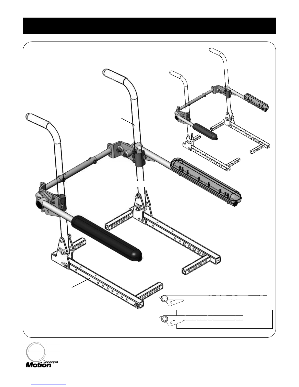
11..00 OOvveerrvviieeww DDrraawwiinnggss
TIL
TILTT
-ONL
-ONL
Y CANTILEVER
Y CANTILEVER
ARMRESTS
ARMRESTS
Seat Side Frame
Tilt-Only
Back Cane
DESK LENGTH
DESK LENGTH* Cantilever Armrest Ass’y
FULL
FULL
LENGTH
LENGTH* Cantilever Armrest Ass’y
*Desk Length Armrest Tube = 16-5/8”
*Full Length Armrest Tube = 21-3/8”
Page 5
- 5 -
TRD0274, Cantilever Armrest (Tilt-Only) Installation & Set-up, Rev 1.0 - March 30, 2009
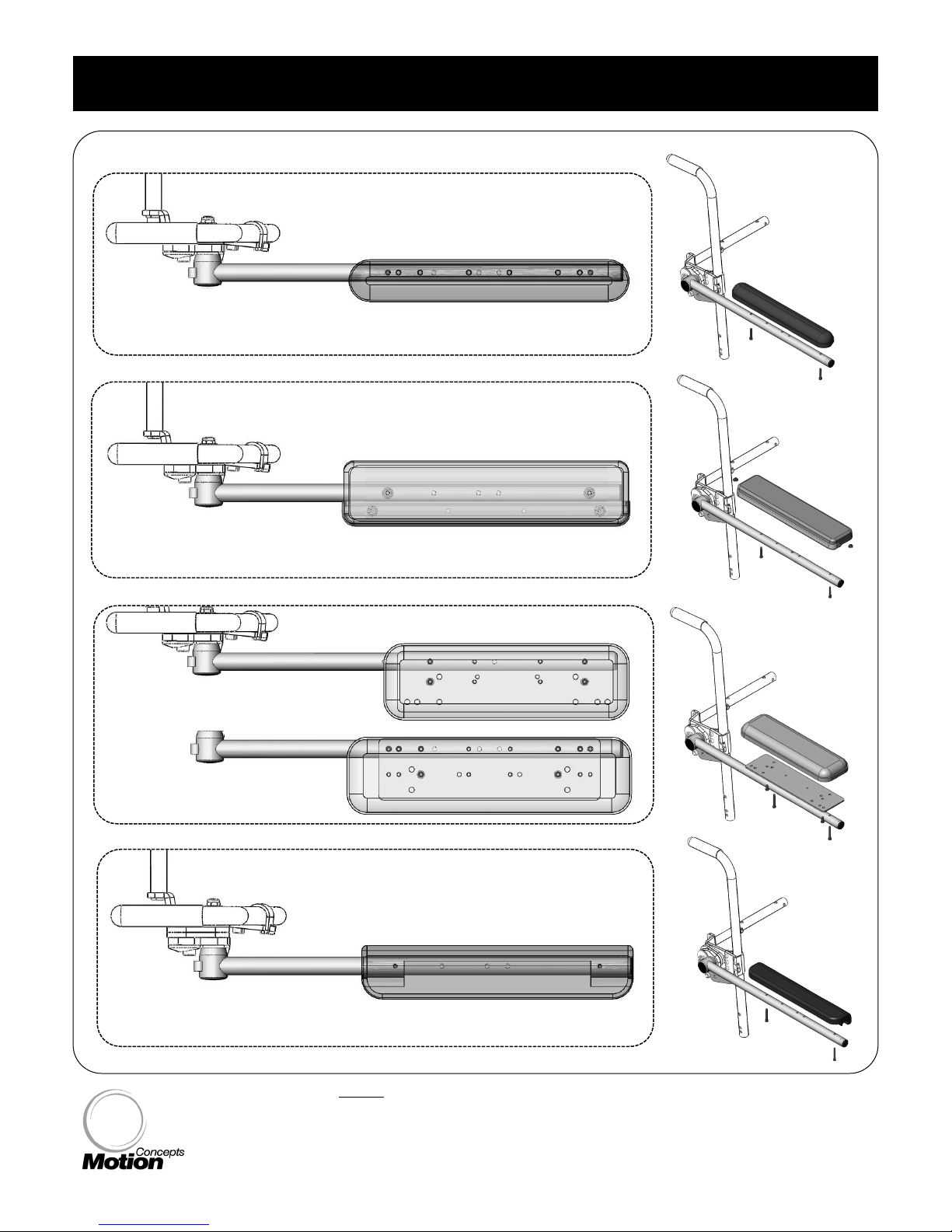
11..00 OOvveerrvviieeww DDrraawwiinngg
Standard Arm Pad (full)
OVERHEAD VIEW
Gel Arm Pad (long)
Gel Arm Pad (short)
Standard Arm Pad (full)
Tilt-Only Cantilever Armrest -
ARMP
ARMP
AD OPTIONS
AD OPTIONS*
Waterfall Arm Pad (full)
*NOTE: Desk Length armrest tubes will utilize desk length armpads
Page 6
- 6 -
2.1
2.1
Cane Clamp Installa
Cane Clamp Installa
tion
tion
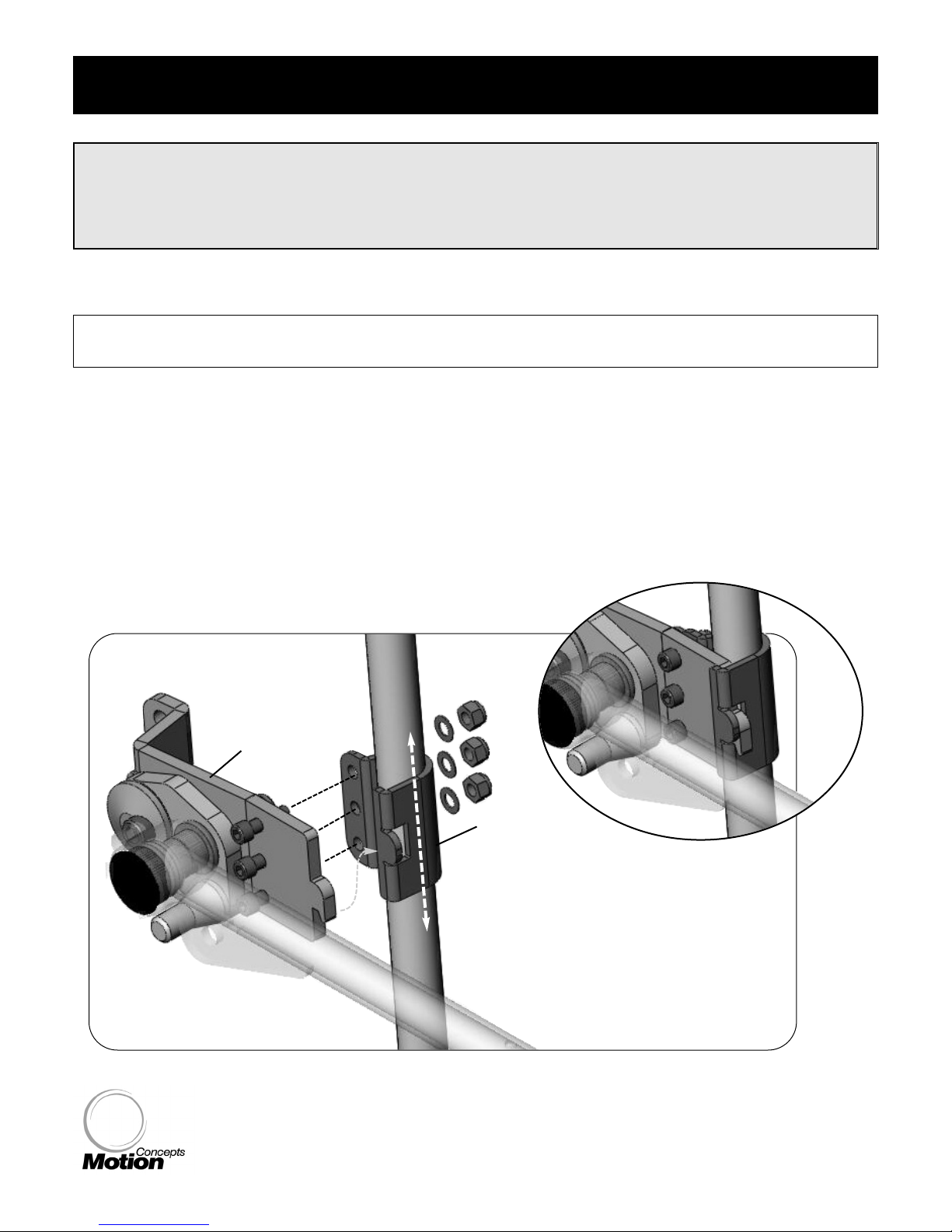
1. Loosely install the cantilever armrest onto each back cane (left and right) via the cane clamp assembly- see
Figure 1.0 below.
2. Working on one back cane at a time, determine the desired height of the cantilever armrest and secure the
cane clamp assembly onto the back cane using the hardware provided. (Note: fine tune height adjustments
may be required to complete the installation of the crossbar assembly- see Section 2.2)
Note
: the height of the left and right cantilever armrest assemblies may be
offset
offset from each other by up
to 1.5” (if desired); please refer to Figure 2.0 - Crossbar Installation for instructions.
Important!
The following section provides installation and adjustment instructions for the Tilt-Only Cantilever
Armrest Assembly. If the Cantilever Armrest has already been installed on the seating system,
please proceed to
Section 2.4
Section 2.4 for instructions on adjusting the armrest angle.
Note: The following instructions/images show the installation of the cantilever armrest onto the
right side of the seating system, repeat all steps indicated to complete the left armrest installation.
cane clamp
starting on either side of the wheelchair
determine the desired height* for the
cantilever armrest, and secure the cane
clamp assembly onto the back cane
*note: the left and right armrest assemblies may
be offset from each other by up to 1.5” (if desired)
Cantilever Armrest Tube
Tilt Back Cane
Figure 1.0
mounting
plate
right cantilever assembly shown
22..00 IInnssttaallllaattiioonn && AAddjjuussttmmeenntt
Page 7
- 7 -
TRD0274, Cantilever Armrest (Tilt-Only) Installation & Set-up, Rev 1.0 - March 30, 2009
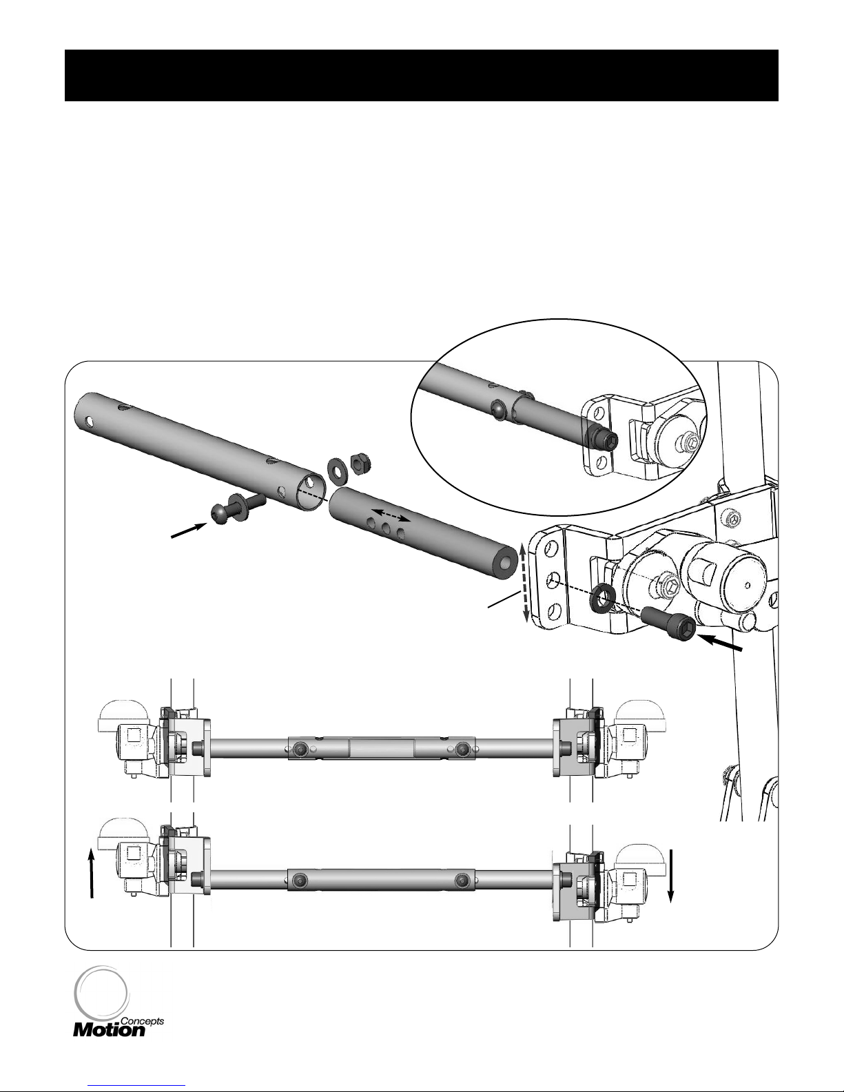
1. The crossbar is installed between the back canes of the seating system .
2. The crossbar assembly utilizes an adjustable spreader bar/ tube which secures into a cross support on
either side. Each cross support is in turn secured into one of three optional mounting holes* at the rear of
the clamp mounting plate. (refer to Figure 2.0 below)
*note: the optional mounting holes can be utilized to avoid interefence with other back hardware/ fixtures,
or may also be used to
offset
offset the left and right armrest heights by up to 1.5” (hole spacing is offered in
3/4” increments)
2.2
2.2CrCr
ossbar Installa
ossbar Installa
tion
tion
width adjustment
crossbar is height adjustable to prevent
interefence issues, or to allow
offset
offset armrest
heights of up to 1.5” (3/4” increments)
Figure 2.0
22..00 IInnssttaallllaattiioonn && AAddjjuussttmmeenntt
adjustable spreader bar
cross support
Standard Crossbar Assembly
Offset Crossbar Assembly
(maximum 1.5” offset shown)
Page 8
- 8 -
2.3 (Optional) Le
2.3 (Optional) Levverer
-Loc
-Loc
k Handle f
k Handle f
or Cantile
or Cantilevv
er
er ArArmrmr
ests
ests
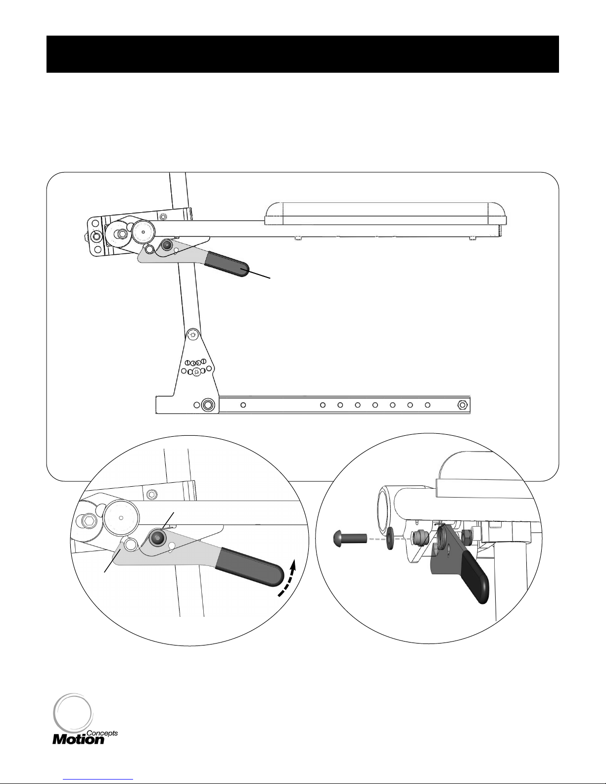
1. The optional lever lock handle is secured to the mounting tab at the rear of the armrest tube. The
lever-lock utilizes a spring operated latch mechanism to prevent the armrest from being raised unless
the latch is released. Refer to Figure 3.0 below for installation instructions.
lever-lock handle
(optional)
Lift to Release
Figure 3.0
22..00 IInnssttaallllaattiioonn && AAddjjuussttmmeenntt
latch
spring
Armrest Tube
FRONT VIEW
Page 9
- 9 -
TRD0274, Cantilever Armrest (Tilt-Only) Installation & Set-up, Rev 1.0 - March 30, 2009
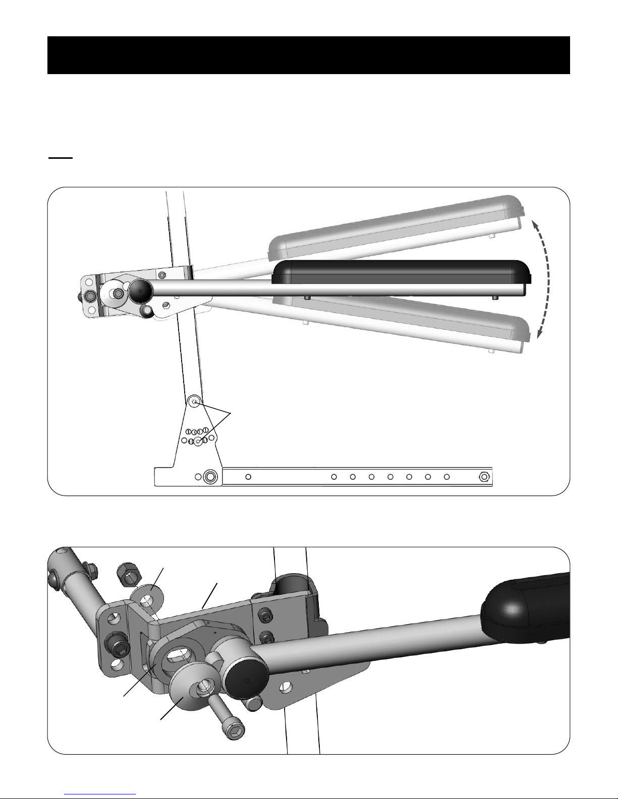
1. The tiilt-only style cantilever armrest offers a unique adjustment feature that allows the armrest to be
adjusted to any angle within a 20 degree range (plus/minus (+/-) 10 degrees).
Note
: Figure 4.0 below shows the armrest poisitions (range of adjustment) based on an initial tilt
backcane angle of
95 degrees
95 degrees (standard configuration).
2.4
2.4
Cantile
Cantilevv
er
er ArArmrmr
est
est
Ang
Ang
le
le
Adjustment
Adjustment
22..00 IInnssttaallllaattiioonn && AAddjjuussttmmeenntt
Figure 4.0
+10 degrees
-10 degrees
A. (
standard set-up)
B. (fully raised)
C. (
fully lowered)
Refer to Figures 6a/b & 7.0 (p.10-11) for detailed
images regarding armrest angle adjustments
2. Cantilever armrest angle adjustments are dictated by the cam mechanism (cam lobe & hardware) in
conjunction with the slotted design of the clamp mounting plate. See Figure 5.0 below.
cam lobe
mounting plate
tilt backcane installed at 95
o
(standard configuration)
Figure 5.0
support washer
adjustment plate
Page 10
- 10 -
3. Adjusting the armrest angle:
2.4
2.4
Cantile
Cantilevv
er
er ArArmrmr
est
est
Ang
Ang
le
le
Adjustment
Adjustment (... cont’d)
22..00 IInnssttaallllaattiioonn && AAddjjuussttmmeenntt
Refer to Figure 7.0 for additional angle adjustment images of the Cantilever Tilt-Only Armrest.
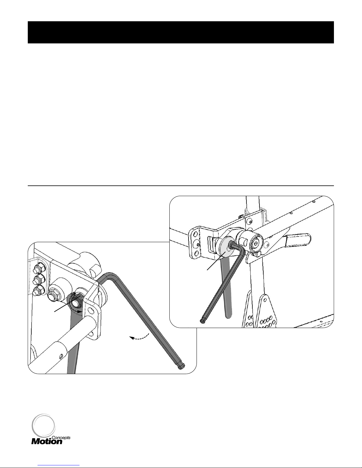
INSIDE VIEW
To adjust armrest angle:
- loosen the main bolt for the cam mechanism
- using the allen key as a lever, rotate the cam lobe/
mechanism up or down to adjust the armrest angle.
- tighten the main bolt to lock the armrest into position
main bolt
cam lobe
Figure 6a.
Figure 6b.
i. Before making adjustments, place the seating system in the fully upright position.
ii. To adjust the angle of the cantilever armrest, simply loosen the cam mechanism by loosening the
main bolt on the inside of the mounting plate in assembly (just enough for the cam mechanism to
rotate) (refer to Figure 6a and 6b. below).
iii. With the main bolt loosened, use the Allen Key to rotate the Cam Lobe assembly. By rotating the
cam lobe up and down, the cantilever armrest angle will adjust accordingly- See Figure 7.0 p.11.
iv. Once the desired the angle is set, use the allen key to hold the armrest (cam mechanism) in position,
and use the wrench to re-tighten the main bolt and lock the armrest in place.
Note:
if desired, the left & right armrests may be adjusted to provide a unique set-up on each armrest.
loosen the main bolt
Page 11
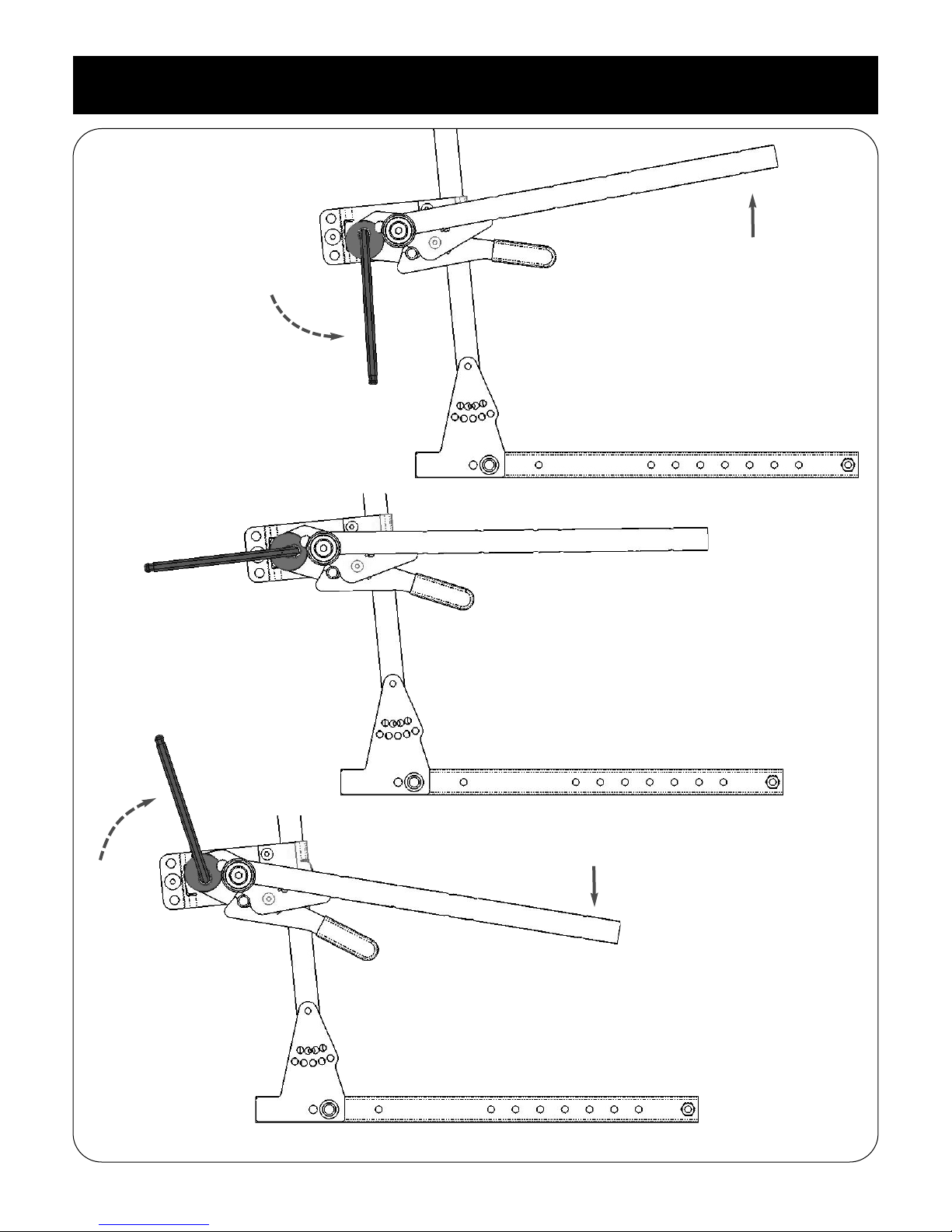
- 11 -
TRD0274, Cantilever Armrest (Tilt-Only) Installation & Set-up, Rev 1.0 - March 30, 2009
22..00 IInnssttaallllaattiioonn && AAddjjuussttmmeenntt
Figure 7.0
Ang
Ang
le
le
Adjustments
Adjustments
rotate the cam upward to
lower the armrest angle
rotate the cam downward to
lower the armrest angle
(parallel to seat frame)
Note:
above images are shown with the lever lock handle (optional)
SSttandard
andard Catilever Armrest Set-Up
Raised
Raised Catilever Armrest Set-Up
Lowered
Lowered Catilever Armrest Set-Up
Page 12

UUSSAA
700 Ensminger Rd. Suite 112
Tonawanda, NY, USA 14150
716-447-0050
888-433-6818
CCaannaaddaa
84 Citation Dr. Units 1-3
Concord, Ontario,
Canada L4K 1C9
905-695-0134
www.motionconcepts.com
 Loading...