

Page 1
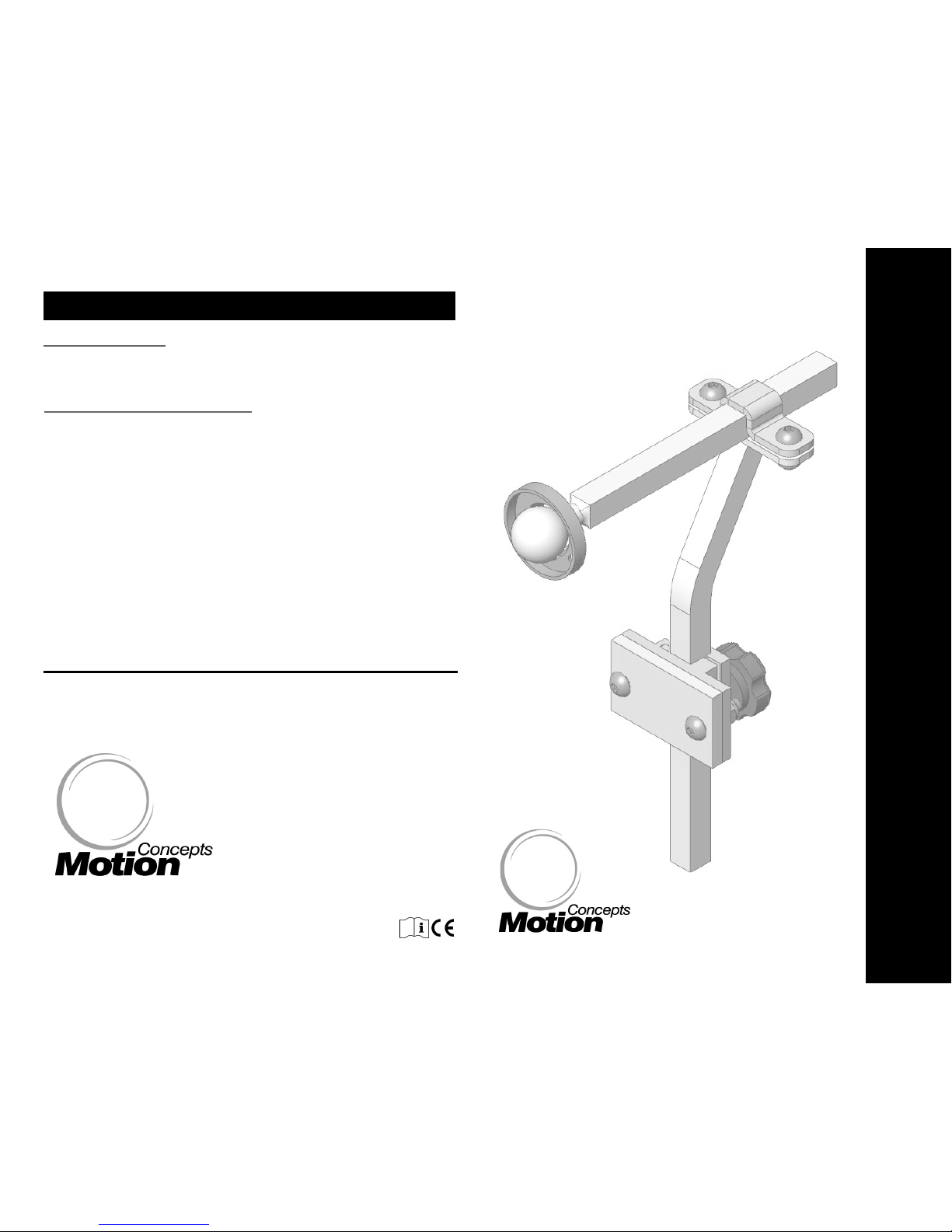
Installation Manual
MM
MM
aa
aaTTTT
RR
RRxxxx
HH
HH
ee
ee
aa
aa
dd
ddrrrr
ee
eesssstttt
IIIInn
nnsssstttt
aa
aallllllll
aa
aattttiiii
oo
oo
nn
nn
Standard
Standard
Mounting
Mounting
Hardware
Hardware
wwwwww..mmoottiioonncc oonncceeppttss..ccoomm
iinnffoo@@mm oottiioonnccoonncceepptt ss..ccoomm
USA
770000 EEnnssmmiinnggeerr RRdd.. SSuuiittee 111122
TToonnaawwaannddaa,, NNYY 1144115500
TTool
TToollll FFrreeee FFaaxx:: 11..888888..443333..66883344
Canada
8844 CCiittaattiioonn DDrriivvee
CCoonnccoorrdd,, OOnnttaarriioo LL44KK 3
TToollll FFrreeee TTeell:: 11..886666..774488..77994433
TTeell:: 990055..669955..00113344
FFaaxx:: 990055..669955..00113388
The headrest clamp is secured to the wheelchair back using the hardware provided.
Whenever possible, the clamp should be installed into existing mounting holes in the
backpan. If no holes are provided, holes may be drilled in the desired location using
the mounting plate as a template1.
The overall height of the headrest pad/ mounting post can be adjusted via the
main headrest clamp assembly. The depth of the headrest is adjusted along the
horizontal headrest rod and secured in position by the upper clamp assembly.
The headrest pad is secured to the mounting post via the corresponding mounting
ring and headrest hardware provided. (note: prior to tightening the mounting
hardware, the headrest pad can also be adjusted to the desired position/angle
around the pivot ball at the end of the headrest rod).
1
Important! - before drilling/modifying any backpan, be certain to contact
the back manufacturer to ensure the back is recommended to support a
headrest application.
INSTALLATION INSTRUCTIONS
:
Wrenches: 7/16"
Allen Key: 5/32”, 1/8”
TOOLS REQUIRED:
Power Drill
1/4” Drill Bit
Phillips Screwdriver
Tape Measure/Ruler
MaTRx Headrests with Standard Mounting Hardware
- 3 -
Page 2
MaTRx Headrests with Standard Mounting Hardware
MaTRx Headrests with Standard Mounting Hardware
- 2 -- 1 -
HEADREST KITS:
Standard Mounting Hardware
(excluding headrest ass’y)
Standard Pad
Ottobock Pad-Lg
Stealth Pad-Sm (10”) Stealth Pad-Lg (14”)
Ottobock Pad-Sm
SPSH OPSH-S
OPSH-L
STSH-S
STSH-L
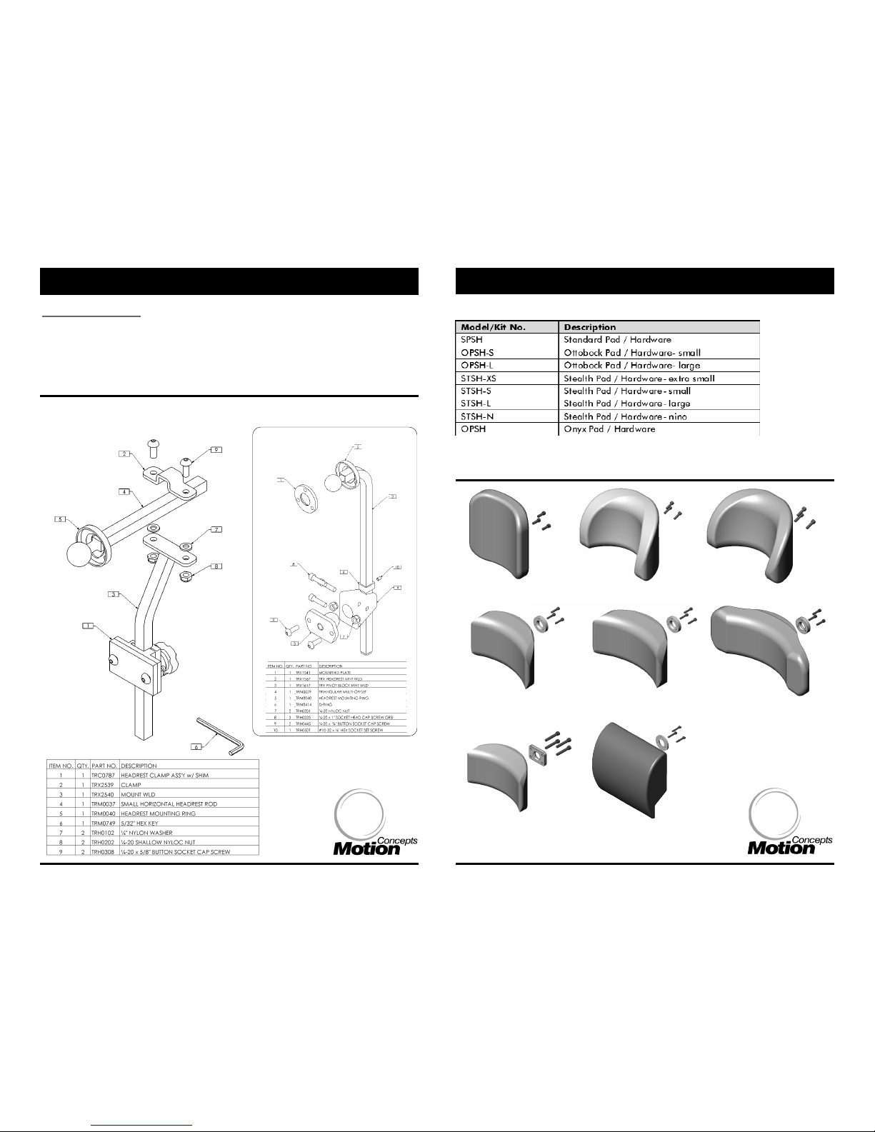
Figure 2.0 - Optional Headrest Assemblies
Headrest Kit Options*
(refer to Figure 2.0 for the various Headrest Ass’y Options)
The headrest installation hardware/components provided in each Standard Mounting
Hardware Kit are identical, with the exception of the Onyx-Style headrest. (Refer to
Figure 1.0 & Figure 1A below). The Onyx headrest utilizes a unique mounting
hardware kit. There are seven (7) optional headrest assemblies available for use with
our standard mounting hardware. (Headrest options are illustrated in Figure 2.0).
TRD0244- MaTRx Headrests- Standard Mounting Hardware Installation Manual- Rev 2.0
Note: each headrest includes corresponding mounting hardware)
Onyx Pad
OPSH
STSH-XS
Stealth Pad- Xtra Sm (8”)
STSH-N
Stealth Pad- Nino (6”)
Figure 1.0
Onyx Style Mounting Hardware
(*requires Onyx Style mounting
hardware- see Figure 1A)
Figure 1A
 Loading...