

Page 1

Name
Date
ECN # - General Statement of Change
Version
A Love
2009-10-09
ECN-2420 INITIAL RELEASE
A00
MOTION MCW
WITH MEDIAWAVE COMPUTER
INSTALLATION AND ASSEMBLY
PROCEDURE
Document Number: 002-15-0010
Revision History
THIS DOCUMENT CONTAINS INFORMATION CONFIDENTIAL AND PROPRIETARY TO MOTION COMPUTING
AND SHALL NOT BE REPRODUCED OR TRANSFERRED TO OTHER DOCUMENTS OR DISCLOSED TO
OTHERS OR USED FOR ANY PURPOSE OTHER THAN THAT FOR WHICH IT WAS OBTAINED WITHOUT THE
EXPRESSED WRITTEN CONSENT OF MOTION COMPUTING.
PROPRIETARY NOTE
Page 2

Motion MCW with MediaWave Computer – Installation and Assembly Procedure
Table of Contents
REVISION HISTORY ................................................................................................................................................ I
TABLE OF CONTENTS ...........................................................................................................................................II
1. BASE WITH POWER SUPPLY SHROUD INSTALLED ............................................................................. 1
1.1 REMOVE THE PLASTIC SHROUD THAT COVERS THE POWER SUPPLY .................................................................. 1
2. COLUMN ASSEMBLY ..................................................................................................................................... 1
2.1 LAY BASE ON ITS BACK .................................................................................................................................... 2
2.2 POSITION COLUMN ABOVE BASE ....................................................................................................................... 2
2.3 INSERT BOLTS THROUGH THE BOTTOM OF THE CART INTO THE COLUMN. THREAD EACH BOLT BEFORE FULLY
TIGHTENING ANY BOLT. TIGHTEN ALL FOUR BOLTS. ........................................................................................ 3
2.4 SET CART UPRIGHT ........................................................................................................................................... 3
2.5 REMOVE ONE SCREW AND LOOSEN THE OTHER SCREW OF THE COLUMN TOP PLATE ......................................... 4
2.6 INSERT DECORATIVE COVER IN THE BACK OF THE COLUMN CHANNEL GROVES. ............................................... 4
2.7 SLIDE DECORATIVE COVER DOWN TO WITHIN 24 INCHES OF THE BASE ............................................................. 4
2.8 ROUTE CABLES BEHIND THE DECORATIVE COVER ............................................................................................ 5
2.9 SLIDE DECORATIVE COVER TO THE BOTTOM OF THE COLUMN .......................................................................... 5
2.10 HOLDING CABLE IN THE CHANNEL AND INSERT SECOND DECORATIVE COVER IN THE BACK COLUMN CHANNEL
GROVES ............................................................................................................................................................ 5
2.11 SLIDE THE DECORATIVE COVER DOWN SO IT TOUCHES THE FIRST COVER ......................................................... 6
3. INSTALLING THE WORK SURFACE AND DRAWER ............................................................................. 6
3.1 REMOVE THE DRAWERS BY PRESSING THE PLASTIC RELEASE TABS ON THE INSIDE OF THE DRAWER GLIDE
RAILS................................................................................................................................................................ 6
3.2 NOTE WHERE THE ALLEN SET SCREWS ARE LOCATED ...................................................................................... 7
3.3 SLIDE THE WORK SURFACE DRAWER ASSEMBLY MOUNTING BRACKET INTO THE ADJUSTABLE RAIL LOCATED
ON THE FRONT COLUMN ................................................................................................................................... 7
3.4 SLIDE THE WORK SURFACE DRAWER ASSEMBLY DOWN THE RAIL TO ABOUT 2 INCHES (4.4 CM) FROM THE
BOTTOM OF THE RAIL. ...................................................................................................................................... 7
3.5 TIGHTEN THE SET SCREWS................................................................................................................................ 8
3.6 FULLY TIGHTEN THE SET SCREWS ..................................................................................................................... 8
3.7 REINSTALL THE DRAWER BY SLIDING IT ONTO THE DRAWER RAILS ................................................................ .. 9
4. ASSEMBLE THE CPU/MONITOR VESA MOUNT ASSEMBLY ............................................................ 10
4.1 ATTACH METAL SPACERS TO THE FRONT CPU VESA MOUNT PLATE CORNERS ............................................. 10
4.2 PLACE NYLON SPACERS OVER THE MONITOR VESA MOUNT PLATE THREADED INSERTS WHERE ARROWS
INDICATE ................................................................................................................................ ........................ 10
4.3 INSERT SCREWS THROUGH THE FRONT CPU VESA MOUNT PLATE HOLE AND THROUGH THE NYLON SPACERS,
THREADING THEM INTO THE MONITOR VESA MOUNT PLATE THREADED INSERTS ........................................ 11
4.4 ATTACH THE FLUSH TILTING VESA MOUNT BRACKET TO THE BACK CPU VESA MOUNT PLATE ................ 11
4.5 PLACE THE MEDIA WAVE COMPUTER ONTO THE FRONT CPU VESA MOUNT PLATE, EVENLY SPACED
BETWEEN THE METAL SPACERS AND CONNECTORS FACING DOWN ................................................................. 11
4.6 ATTACH THE BACK CPU VESA MOUNT PLATE TO THE FRONT CPU VESA MOUNT PLATE, USING THE
THREADED METAL SPACERS ATTACHED TO THE FRONT PLATE........................................................................ 12
5. INSTALL THE MONITOR/CPU MOUNT ASSEMBLY BY SLIDING THE FLUSH TILTING VESA
MOUNT BRACKET INTO THE FRONT OF THE COLUMN RAIL ...................................................... 12
5.1 POSITION THE VESA MOUNT BRACKET ABOUT ONE INCH FROM THE TOP OF THE COLUMN RAIL AND SECURE
BY TIGHTENING THE SET SCREWS ................................................................................................................... 13
6. ASSEMBLE THE BATTERY GAUGE HOUSING ..................................................................................... 13
ii Document No. 002-15-0010
Motion Proprietary & Confidential
Copyright © 2009 Motion Computing, Inc. as an unpublished work
Page 3

Motion MCW with MediaWave Computer – Installation and Assembly Procedure
7. ASSEMBLE THE MOUNTING PLATE AND BATTERY GAUGE ......................................................... 13
7.1 PLACE THE MOUNTING PLATE WITH THE BACK SIDE FACING UP, AND SET THE BATTERY GAUGE PLATE OVER
THE FIXED MOUNT SCREWS. ........................................................................................................................... 14
7.2 ATTACH THE BATTERY GAUGE HOUSING TO THE MOUNTING PLATE. ............................................................ 14
7.3 TURN OVER THE MOUNTING PLATE ASSEMBLY, REMOVE THE ADHESIVE COVER PAPER FROM THE BACK OF
THE BATTERY GAUGE, AND ADHERE THE BATTERY GAUGE TO THE MOUNTING PLATE ASSEMBLY. .............. 15
8. PLUG THE RJ45 BATTERY GAUGE CABLE INTO THE JACK, THROUGH THE HOLE IN THE
BACK OF THE BATTERY GAUGE HOUSING. ........................................................................................ 16
9. ATTACH THE BATTERY GAUGE MOUNT PLATE TO THE BACK CPU VESA MOUNT PLATE17
10. PLUG IN AND SECURE MONITOR CABLES ........................................................................................... 18
11. PLUG IN AND SECURE COMPUTER CABLES ....................................................................................... 18
12. DRESS THE CABLES AT THE MONITOR AND CPU USING CORRUGATED CABLE WRAP,
SECURING WITH CABLE TIES. ................................................................................................................. 19
13. PULL THE EXCESS CABLE LENGTH TO THE BOTTOM OF THE COLUMN ................................. 19
14. DRESS THE CABLES AT THE BOTTOM OF THE COLUMN USING CORRUGATED CABLE
WRAP, SECURING WITH CABLE TIES, AND PULLING THE EXCESS CABLE LENGTH INTO
THE SHEET METAL BASE. ......................................................................................................................... 20
15. INSTALL BATTERIES WITH TERMINAL POINTING OUT. IF THE BATTERIES ARE TURNED
IN, THE THERMAL SENSORS WILL READ INCORRECTLY. ............................................................ 21
16. THE UNPAINTED SIDE OF THE THERMAL SENSOR MUST BE IN CONTACT WITH THE
BATTERY POST. ............................................................................................................................................ 22
17. MAKE SURE BATTERY CONNECTIONS ARE TIGHT ON BOTH BATTERIES .............................. 22
18. REINSTALL THE SHROUD AND COLUMN TOP PLATE ..................................................................... 23
iii Document No. 002-15-0010
Motion Proprietary & Confidential
Copyright © 2009 Motion Computing, Inc. as an unpublished work
Page 4
Motion MCW with MediaWave Computer – Installation and Assembly Procedure
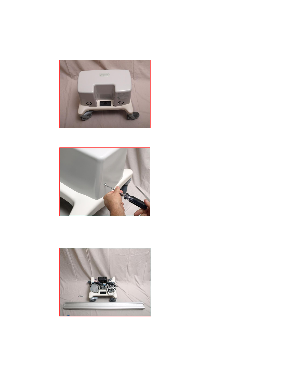
1. Base with power supply shroud installed
1.1 Remove the plastic Shroud that covers the power supply
Tip: Setting the wheel locks will help hold the Base assembly in place.
2. Column assembly
1 Document No. 002-15-0010
Motion Proprietary & Confidential
Copyright © 2009 Motion Computing, Inc. as an unpublished work
Page 5
Motion MCW with MediaWave Computer – Installation and Assembly Procedure
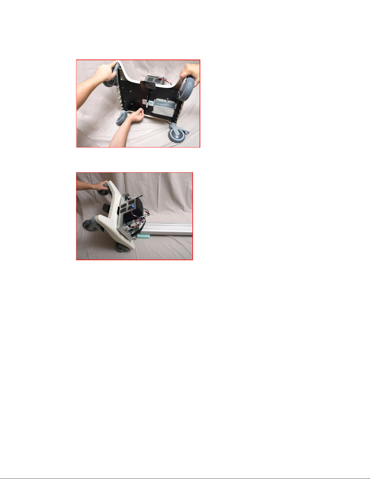
2.1 Lay base on its back
2.2 Position column above base
2 Document No. 002-15-0010
Motion Proprietary & Confidential
Copyright © 2009 Motion Computing, Inc. as an unpublished work
Page 6
Motion MCW with MediaWave Computer – Installation and Assembly Procedure
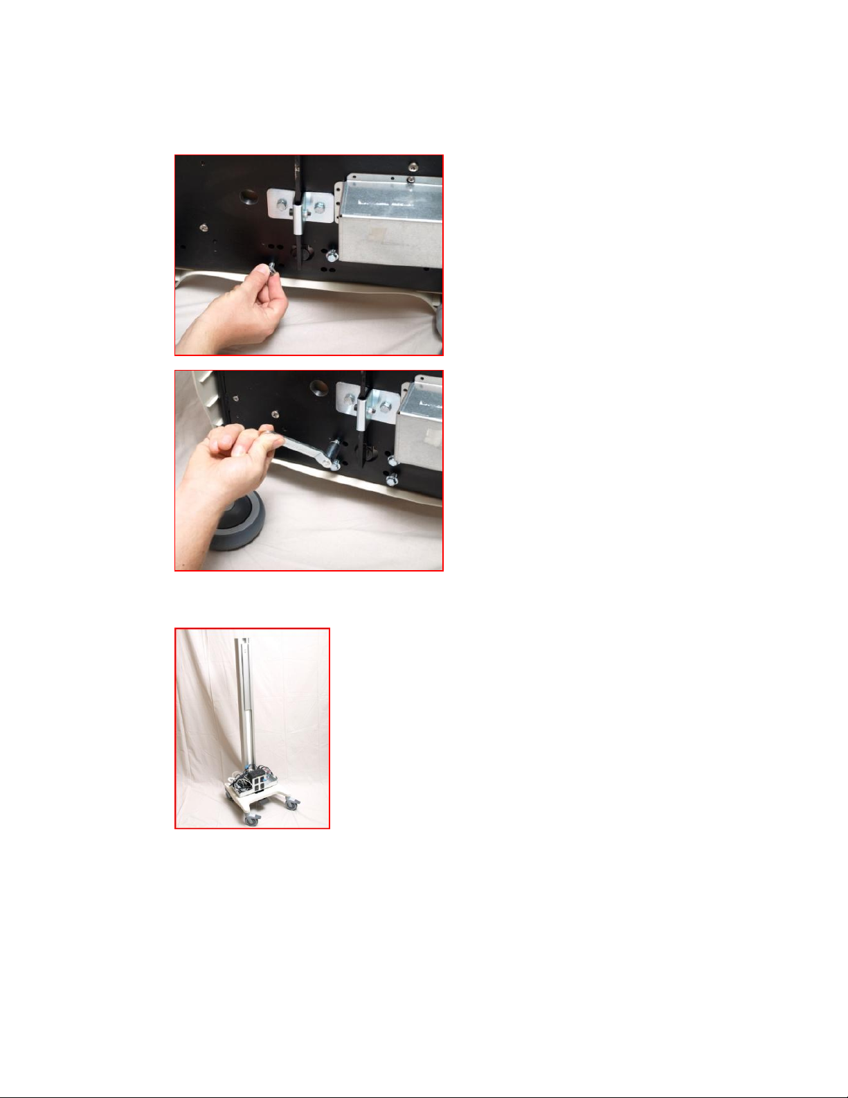
2.3 Insert bolts through the bottom of the cart into the column. Thread each
bolt before fully tightening any bolt. Tighten all four bolts.
2.4 Set cart upright
3 Document No. 002-15-0010
Motion Proprietary & Confidential
Copyright © 2009 Motion Computing, Inc. as an unpublished work
Page 7
Motion MCW with MediaWave Computer – Installation and Assembly Procedure
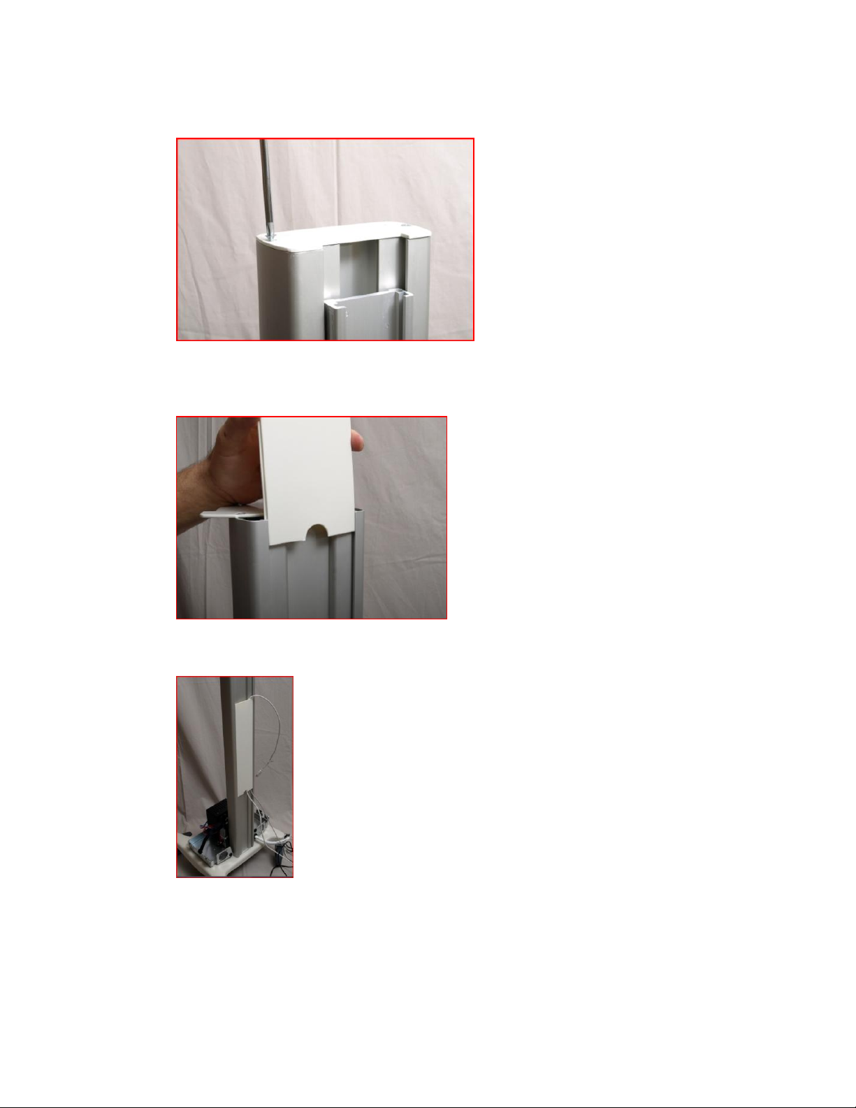
2.5 Remove one screw and loosen the other screw of the column top plate
2.6 Insert decorative cover in the back of the column channel groves.
Note: Notice the half moon on the first decorative cover
2.7 Slide decorative cover down to within 24 inches of the base
4 Document No. 002-15-0010
Motion Proprietary & Confidential
Copyright © 2009 Motion Computing, Inc. as an unpublished work
Page 8
Motion MCW with MediaWave Computer – Installation and Assembly Procedure
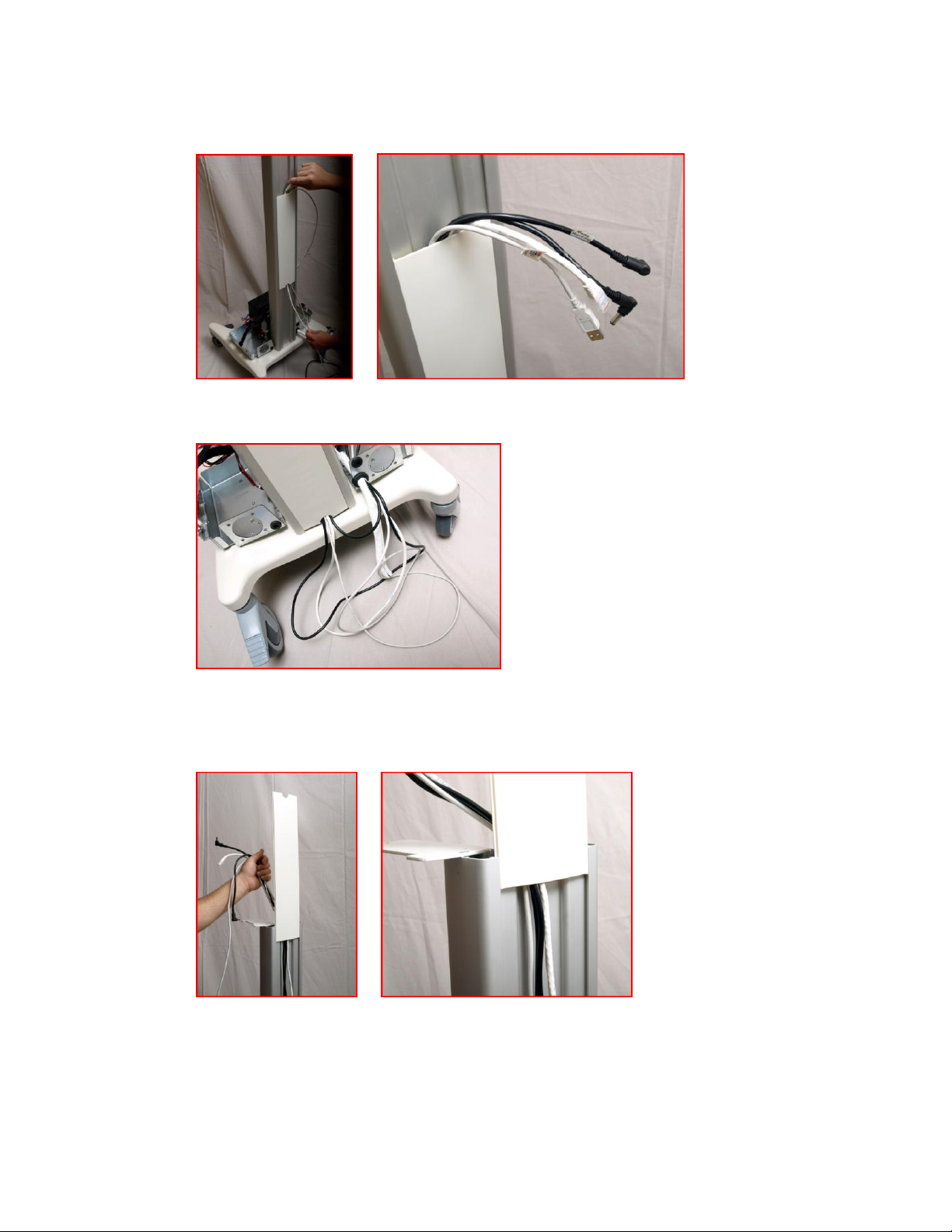
2.8 Route cables behind the decorative cover
2.9 Slide decorative cover to the bottom of the column
2.10 Holding cable in the channel and insert second decorative cover in the
back column channel groves
Note: The half moon cut out is up
5 Document No. 002-15-0010
Motion Proprietary & Confidential
Copyright © 2009 Motion Computing, Inc. as an unpublished work
Page 9

Motion MCW with MediaWave Computer – Installation and Assembly Procedure
2.11 Slide the decorative cover down so it touches the first cover
3. Installing the work surface and drawer
Note: The work surface and drawer come pre-assembled.
3.1 Remove the drawers by pressing the plastic release tabs on the inside of
the drawer glide rails.
6 Document No. 002-15-0010
Motion Proprietary & Confidential
Copyright © 2009 Motion Computing, Inc. as an unpublished work
Page 10

Motion MCW with MediaWave Computer – Installation and Assembly Procedure
3.2 Note where the Allen set screws are located
3.3 Slide the work surface drawer assembly mounting bracket into the
adjustable rail located on the front column
3.4 Slide the work surface drawer assembly down the rail to about 2 inches (4.4
cm) from the bottom of the rail.
7 Document No. 002-15-0010
Motion Proprietary & Confidential
Copyright © 2009 Motion Computing, Inc. as an unpublished work
Page 11

Motion MCW with MediaWave Computer – Installation and Assembly Procedure
3.5 Tighten the set screws
3.6 Fully tighten the set screws
Note: Failure to fully tighten the set screws may result in the assembly
dropping
8 Document No. 002-15-0010
Motion Proprietary & Confidential
Copyright © 2009 Motion Computing, Inc. as an unpublished work
Page 12

Motion MCW with MediaWave Computer – Installation and Assembly Procedure
3.7 Reinstall the drawer by sliding it onto the drawer rails
9 Document No. 002-15-0010
Motion Proprietary & Confidential
Copyright © 2009 Motion Computing, Inc. as an unpublished work
Page 13

Motion MCW with MediaWave Computer – Installation and Assembly Procedure
4. Assemble the CPU/Monitor VESA Mount assembly
4.1 Attach metal spacers to the front CPU VESA Mount plate corners
4.2 Place nylon spacers over the Monitor VESA Mount plate threaded inserts
where arrows indicate
10 Document No. 002-15-0010
Motion Proprietary & Confidential
Copyright © 2009 Motion Computing, Inc. as an unpublished work
Page 14

Motion MCW with MediaWave Computer – Installation and Assembly Procedure
4.3 Insert screws through the front CPU VESA Mount plate hole and through
the nylon spacers, threading them into the Monitor VESA Mount plate
threaded inserts
4.4 Attach the Flush Tilting VESA Mount bracket to the back CPU VESA Mount
plate
4.5 Place the Media Wave Computer onto the front CPU VESA Mount plate,
evenly spaced between the metal spacers and connectors facing down
11 Document No. 002-15-0010
Motion Proprietary & Confidential
Copyright © 2009 Motion Computing, Inc. as an unpublished work
Page 15

Motion MCW with MediaWave Computer – Installation and Assembly Procedure
4.6 Attach the back CPU VESA Mount plate to the front CPU VESA Mount plate,
using the threaded metal spacers attached to the front plate
5. Install the Monitor/CPU Mount assembly by sliding
the Flush Tilting VESA Mount bracket into the front
of the column rail
12 Document No. 002-15-0010
Motion Proprietary & Confidential
Copyright © 2009 Motion Computing, Inc. as an unpublished work
Page 16

Motion MCW with MediaWave Computer – Installation and Assembly Procedure
5.1 Position the VESA Mount bracket about one inch from the top of the
column rail and secure by tightening the set screws
6. Assemble the Battery Gauge housing
Note position of housing square cutout (offset to left) and cover hole (offset to
bottom)
7. Assemble the Mounting plate and Battery Gauge
13 Document No. 002-15-0010
Motion Proprietary & Confidential
Copyright © 2009 Motion Computing, Inc. as an unpublished work
Page 17

Motion MCW with MediaWave Computer – Installation and Assembly Procedure
7.1 Place the Mounting plate with the back side facing up, and set the Battery
Gauge plate over the fixed mount screws.
7.2 Attach the Battery Gauge housing to the Mounting plate.
14 Document No. 002-15-0010
Motion Proprietary & Confidential
Copyright © 2009 Motion Computing, Inc. as an unpublished work
Page 18

Motion MCW with MediaWave Computer – Installation and Assembly Procedure
7.3 Turn over the Mounting plate assembly, remove the adhesive cover paper
from the back of the Battery Gauge, and adhere the Battery Gauge to the
Mounting Plate assembly.
15 Document No. 002-15-0010
Motion Proprietary & Confidential
Copyright © 2009 Motion Computing, Inc. as an unpublished work
Page 19

Motion MCW with MediaWave Computer – Installation and Assembly Procedure
8. Plug the RJ45 Battery Gauge cable into the jack,
through the hole in the back of the Battery Gauge
housing.
16 Document No. 002-15-0010
Motion Proprietary & Confidential
Copyright © 2009 Motion Computing, Inc. as an unpublished work
Page 20

Motion MCW with MediaWave Computer – Installation and Assembly Procedure
9. Attach the Battery Gauge Mount plate to the back
CPU VESA Mount plate
17 Document No. 002-15-0010
Motion Proprietary & Confidential
Copyright © 2009 Motion Computing, Inc. as an unpublished work
Page 21

Motion MCW with MediaWave Computer – Installation and Assembly Procedure
10. Plug in and secure monitor cables
11. Plug in and secure computer cables
18 Document No. 002-15-0010
Motion Proprietary & Confidential
Copyright © 2009 Motion Computing, Inc. as an unpublished work
Page 22

Motion MCW with MediaWave Computer – Installation and Assembly Procedure
12. Dress the cables at the Monitor and CPU using
corrugated cable wrap, securing with cable ties.
13. Pull the excess cable length to the bottom of the
column
19 Document No. 002-15-0010
Motion Proprietary & Confidential
Copyright © 2009 Motion Computing, Inc. as an unpublished work
Page 23

Motion MCW with MediaWave Computer – Installation and Assembly Procedure
14. Dress the cables at the bottom of the column using
corrugated cable wrap, securing with cable ties,
and pulling the excess cable length into the sheet
metal base.
20 Document No. 002-15-0010
Motion Proprietary & Confidential
Copyright © 2009 Motion Computing, Inc. as an unpublished work
Page 24

Motion MCW with MediaWave Computer – Installation and Assembly Procedure
15. Install Batteries with terminal pointing out. If the
batteries are turned in, the thermal sensors will
read incorrectly.
21 Document No. 002-15-0010
Motion Proprietary & Confidential
Copyright © 2009 Motion Computing, Inc. as an unpublished work
Page 25

Motion MCW with MediaWave Computer – Installation and Assembly Procedure
16. The unpainted side of the thermal sensor must be
in contact with the battery post.
17. Make sure battery connections are tight on both
batteries
22 Document No. 002-15-0010
Motion Proprietary & Confidential
Copyright © 2009 Motion Computing, Inc. as an unpublished work
Page 26

Motion MCW with MediaWave Computer – Installation and Assembly Procedure
18. Reinstall the shroud and column top plate
23 Document No. 002-15-0010
Motion Proprietary & Confidential
Copyright © 2009 Motion Computing, Inc. as an unpublished work
 Loading...