

Page 1
EDITION - V 1.0
User
Manual
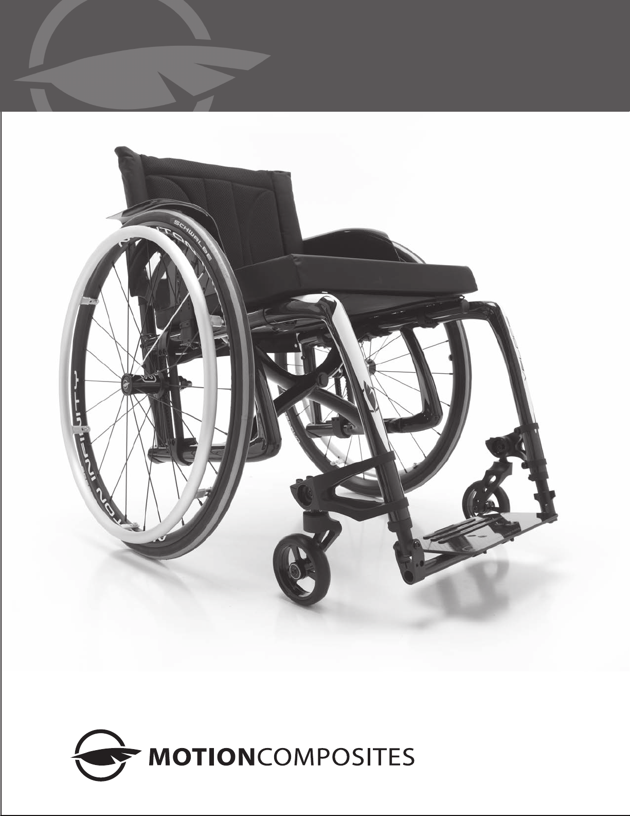
veloce
CARBON T700 ULTRA-LIGHT FRAME
User
Manual
Ultralight Folding Wheelchairs
1
Page 2
veloce
Maintenance
manual&
warranty
information
Dealer: This manual must be given to the user of the VELOCE
wheelchair before its first use.
User: Prior to using the VELOCE wheelchair, carefully read this
manual and keep it for future reference.
For more information about this product, its parts/accessories
and the services provided, please visit :
www.motioncomposites.com
VELOCE
Thank you for selecting the VELOCE wheelchair. Please do
not hesitate to send us your feedback or questions regarding
this product’s reliability, safety, usability, as well as any repair/
maintenance services offered by an authorized Motion
Composites dealer.
Contact information:
Motion Composites Inc.
519 J-Oswald Forest, suite 101
Saint-Roch-de-l’Achigan, Quebec
J0K 3H0 Canada
Phone: 1-866-650-6555
Fax: (450) 588-0200
[email protected]
www.motioncomposites.com
European
authorized
representative :
Advena Ltd
Pure Offices
Plato Close
Warwick
CV34 6WE
United Kingdoms
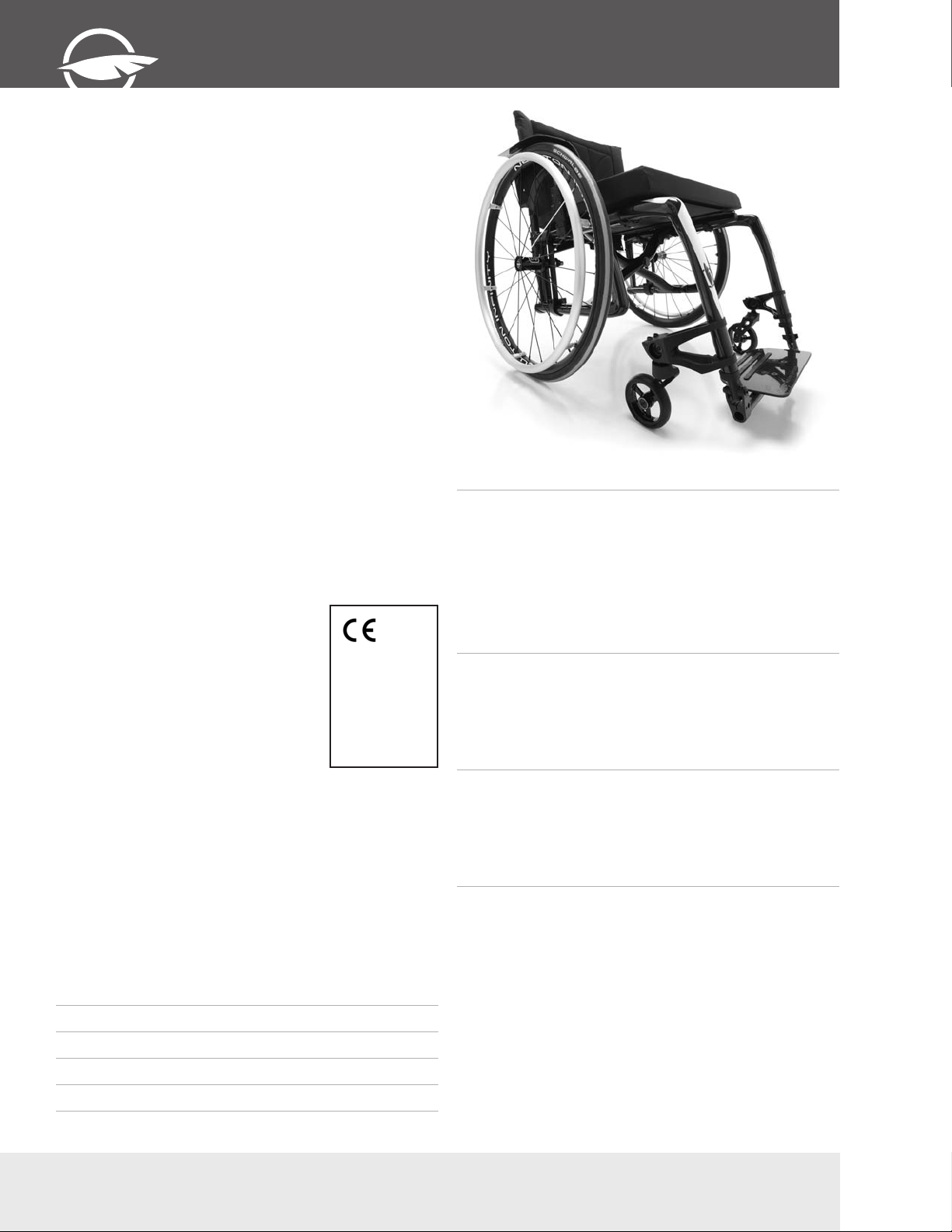
The lightest folding wheelchair
in the world.
The VELOCE is the most technologically advanced wheelchair
for active users. It redefines what a wheelchair should be by
offering unrivaled lightness, rigidity and responsiveness while
keeping the important advantage of a compact folding system.
With a total weight starting at 8.0 kg and a transport weight of
only 5.1 kg, it feels like a Formula 1 but fits in the trunk of a
Mini.
Adjustability without the weight.
The VELOCE is completely adjustable for a perfect fit. You
can easily adjust front and rear seat-to-floor heights, seat angle,
center of gravity and frame angle. All of the options offered on
our line of wheelchairs are also compatible with the Veloce for
true customization.
Follow us!
www.facebook.com/heliowheelchair
www.twitter.com/mcwheelchairs
Important information
If you have any questions about safety, adjustments,
accessories, use, or maintenance, please contact your
authorized Motion Composites dealer.
Please record the following information for future reference:
Date of purchase
Serial Number
Supplier
Address
Telephone
2
Get more mileage out of your energy.
Every little detail of the VELOCE was specifically optimized to
help you go farther. Featuring an entirely symmetrical carbon
fiber crossbrace, oval shaped tubes and oversized pivot axles,
our unique Ultrarigid Folding System (UFS) maximizes frame
rigidity and responsiveness.
Headturning design.
With its spirited Mantis Frame, signature triangular tube shape
and full carbon fiber finish with color highlights, the Veloce is
truly a feast for the senses. It also comes standard with onesided forks for an added sense of flair.
T (450) 588-6555 - 1 866 650-6555 F (450) 588-0200
Page 3
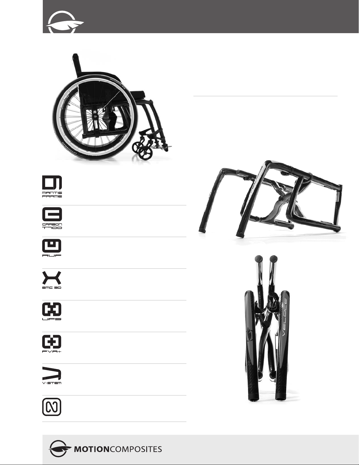
Mantis Frame - Fusion of a boxed frame in the
back for enhanced crossbrace rigidity and
cantilever frame in the front for a minimalist look
EDITION - V 1.0
User
Manual
Introducing
the Mantis Frame.
It’s an entirely new type of wheelchair construction inspired
by the rigidity of box frames and the look and lightness of
cantilever frames. The result is a closed frame in the back to fit
our UFS (Ultrarigid Folding System) and a minimalist front end
offering full configuration possibilities and an outstanding look.
High-Modulus
Carbon Fiber :
The ultimate sophistication.
We use the same high quality material used in F1 and
aerospace to design and build the lightest wheelchairs on earth.
Our T700 high-modulus carbon fiber is unrivaled when it comes
to strength and rigidity. This means our frame is not only ultra
light, but also exceptionally strong.
High-Modulus Carbon T700 - The lightest and most
rigid material available, also renowned for its
vibration dampening properties.
Rigid Unibody Frame - A unibody frame is much
stronger and needs less maintenance than a
standard two-part frame. It also reduces weight
while maximizing propulsion efficiency.
Symmetrical Molded Crossbrace 3D - Entirely
symmetrical carbon fiber crossbrace for reduced
torsion and a better distribution of forces
throughout the frame.
Ultrarigid Folding System - Extremely precise
tolerances and oversized pivot axles for best-inclass propulsion efficiency.
Forged Vertical Axleplate + - Offers the most
precise rear wheel adjustability of the industry.
The vertical mounting maximizes rigidity and
responsiveness.
V Shaped Stem - Stylised stem that offers more
than looks. It provides precise seat-to-floor and
angle adjustments of the front wheel.
Newton Accessories - The whole range of newton
accessories are designed to be light and offer
improved functionalities.
3
Page 4

veloce
Table of contents
WELC OME TO VELOCE
CONTACTING US
IMPO RTANT INFORMATION
TABLE OF CONTENTS
3.
PARTS LIST
4.
4.1 GENERAL WARNING
4.2 SYMBOLS
5.
5.1 STRUCTURE
5.2 DIMENSIONS
5.3 ADJUSTABILITY
6.
6.1 PERIODIC CHECKLIST
6.2 WEIGHT LIMITATION
6.3 WEIGHT TRAINING AND SPORTING ACTIVITIES
7.
8.
8.1. 1 TO REDUCE THE RISK OF ACCIDENT
8.1. 2 ENVIRONMENTAL CONDITIONS
8.1. 3 CAREGIVERS
8.2 RIDING YOUR WHEELCHAIR 8
8.2. 1 BALANCE POINT
8.2. 2 WHEELIES
8.2. 3 TRANSFERRING
8.2. 4 GETTING DRESSED
8.2. 5 REACHING/LEANING/BENDING
8.2. 6 MOVING BACKWARDS
8.2. 7 RAMPS, SLOPES & SIDE HILLS
8.2. 8 OBSTACLES
8.2. 9 CURBS AND STEPS
8.2. 10 MOVING WITH ASSITANCE 9
8.2. 11 MOVING WHITOUT ASSITANCE
8.2. 12 STAIRS
8.2. 13 ESCALATORS
9.
9.1 FOLDING & UNFOLDING
9.1. 1 FOLDING
9.1. 2 UNFOLDING
9.2 WHEEL LOCKS 10
9.4 FOOTREST
9.5 ARMRESTS
9.5. 1 FLIP-BACK ARMRESTS
9.5. 2 REMOVABLE T ARMRESTS
9.5. 3 SWING-AWAY ARMRESTS 11
9.5 SEAT BELTS
9.5. 1 AUTO BUCKLE AND AIRCRAFT BUCKLE SEATBELTS
9.5. 2 VELCRO™ BELT
9.6 ANTI-TIPPER
9.7 REAR WHEELS
9.8 SEAT SLINGS
PRODUCT OVERVIEW
BEFORE USE
TECHNICAL SPECIFICATIONS
SAFETY
TUTORIAL
RIDING YOUR VELOCE
HOW TO USE YOUR VELOCE
2
4
5
6
6
7
7
7
9
10
10.1 SERVICE
10.2 REPLACEMENT PARTS
ORDE RING INFORMATION:
10.3 TOOLS NEEDED
10.4 GENERAL MAINTENANCE
10.4 .1 TIRE PRESSURE
10.5 BACKREST
10.5 .1 REMOVING/INSTALLING THE BACK CANES
10.5 .2 ADJUSTING THE BACK ANGLE
10.5 .3 REMOVING/INSTALLING THE SEAT BELT
10.5 .4 ADJUSTING THE BACKREST HEIGHT 13
SEAT
10.5 .5 INSTALLING/REMOVING STANDARD SEAT UPHOLSTERY
10.6 ARMRESTS
10.6 .1 INSTALLING FLIP-BACK ARMRESTS
10.6 .2 ADJUSTING THE HEIGHT OF FLIP-BACK ARMRESTS
10.6 .3 INSTALLING REMOVABLE T-ARMRESTS AND RIGID SIDEGUARD
10.6 .4 REPLACING ARMRESTS PAD 14
10.6 .5 INSTALLING THE SWING-AWAY ARMREST RECEIVER
10.6 .6 ADJUSTING SWING-AWAY ARMREST HEIGHT
10.7 FRONT RIGGINGS
10.7 .1 ADJUSTING FOOTREST LENGTH
10.8 SEAT 15
10.8 .1 REPLACING SEAT UPHOLSTERY
10.9 SEAT-TO-FLOOR HEIGHT
10.9 .1 CHANGING THE FRONT SEAT-TO-FLOOR HEIGHT
10.9 .2 CHANGING REAR SEAT-TO-FLOOR HEIGHT
10.9 .3 CHANGING FRONT & REAR SEAT-TO-FLOOR HEIGHT
10.1 0 FRONT CASTORS, FORKS AND FORK STEM ASSEMBLIES
10.1 0.1 REMOVING/INSTALLING/REPOSITIONING THE FRONT WHEELS
10.1 0.2 REMOVING/INSTALLING THE CASTER HOUSING
10.1 0.3 REMOVING/INSTALLING THE STEM BOLT ASSEMBLY 16
10.1 0.4 ADJUSTING THE CASTOR HOUSING ANGLE
10.1 1 REAR WHEELS
10.1 1.1 ADJUSTING QUICK-RELEASE AXLES
10.1 1.2 REPLACING/ADJUSTING HAND RIMS 17
USE A PLASTIC TIRE REMOVAL TOOL TO TAKE OFF THE TIRE.
10.1 1.3 ADJUSTING THE REAR AXLE HEIGHT
10.1 1.4 ADJUSTING REAR WHEEL SPACING
10.1 1.5 ADJUSTING THE TOE-IN/TOE-OUT WITH REAR WHEEL CAMBER.
10.1 2 WHEEL LOCKS
10.1 2.1 REPLACING/ADJUSTING THE WHEEL LOCKS
10.1 3 EXTENSION BRAKES 18
10.1 3.1 REPLACING/ADJUSTING THE BRAKE EXTENSION
10.1 4 ANTI-TIPPERS
10.1 4.1 ADJUSTING THE HEIGHT OF THE ANTI-TIPPERS
10.1 5. HEADREST KIT AND HEADREST SUPPORT
10.1 5.1 INSTALLING A HEADREST SUPPORT
10.1 5.2 INSTALLING HEADREST KIT
10.1 6 AMPUTEE EXTENTION PLATE 19
11
12
13
11
I.
ADJUSTMENTS AND MAINTENANCE OF YOUR VELOCE
USING A PARATRANSIT SERVICE
MOTIO N CO MPOS ITES LIM ITED WARRANTY
NOTES
SAFETY INSP ECTI ON C HECK LIST
APPENDIX
23
19
20
22
12
4
T (450) 588-6555 - 1 866 650-6555 F (450) 588-0200
Page 5
3. Product Overview
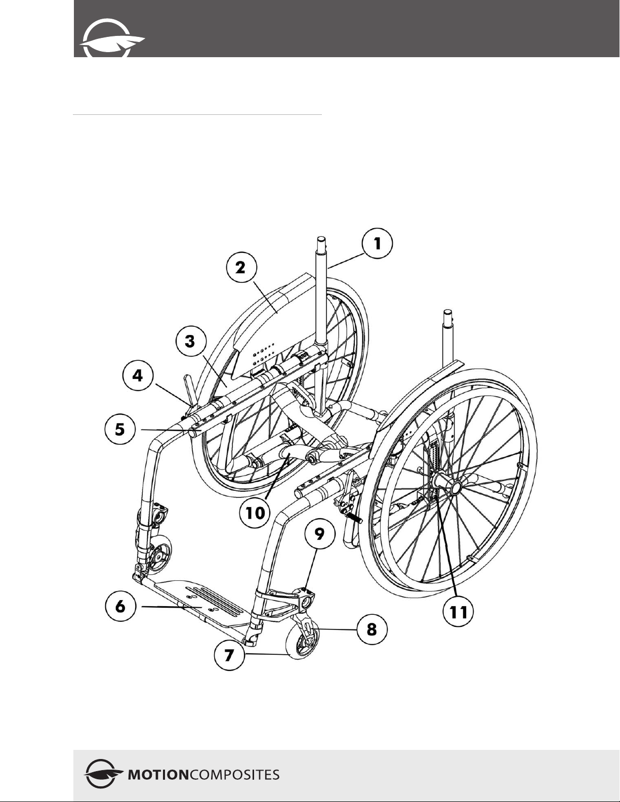
Parts List
1 Back Cane
2 Mudguard
3 Rear wheel
4 Wheel brake
5 Seat rail
6 Footplate
7 Caster
8 Fork
9 Caster Housing
10 Crossbrace
11 Back wheel axle plate
EDITION - V 1.0
User
Manual
5
Page 6
veloce
4. Before use
4.1 General Warning
Your VELOCE wheelchair has been designed by professionals
with proper use of aluminium in mind. DO NOT TRY TO
MODIFY THE FRAME BY ANY MEANS. THE FRAME MAY
BE SEVERELY DAMAGED IN THE EVENT OF DRILLING AND
GRINDING, THUS VOIDING THE WARRANTY. Only use Motion
Composites approved and designed clamps and accessories on
your VELOCE wheelchair.
4.1.1 Note to users:
Carefully read the instructions in this manual before using
or servicing your wheelchair. If you have any questions or
difficulties understanding the following instructions, please
contact a qualified technician; you may also wish to contact a
Motion Composites technician by phone or email (see contact
information on previous page).
4.1.2 Note to dealers & qualified technicians
Read this manual before servicing, repairing, operating
or adjusting the wheelchair. If you have any questions or
difficulties understanding the following instructions, please
contact a qualified technician; you may also wish to contact a
Motion Composites technician by phone or email (see contact
information on previous page).
4.2 Symbols
The following symbols are used throughout this manual. Please
familiarize yourself with their meaning.
Initial setup of your VELOCE wheelchair must be done
by a qualified technician.
The latest version of this manual can be found on our
website at motioncomposites.com
Regular maintenance of your VELOCE will extend the
life of the wheelchair. Take your wheelchair to a
qualified technician every year for inspection and
servicing.
Avoid tightening the screws with an air tool or electric
tool. Final tightening should be done manually.
5. Technical Specifications
5.1 Structure
Frame Folding with C3 cross brace
Material Aerospace grade composites
Weight 7 lbs
(w/o rear wheels & footrest)
Weight capacity 220 lbs
The warning sign indicates important information to
prevent injuries and property damage.
Useful information for the user
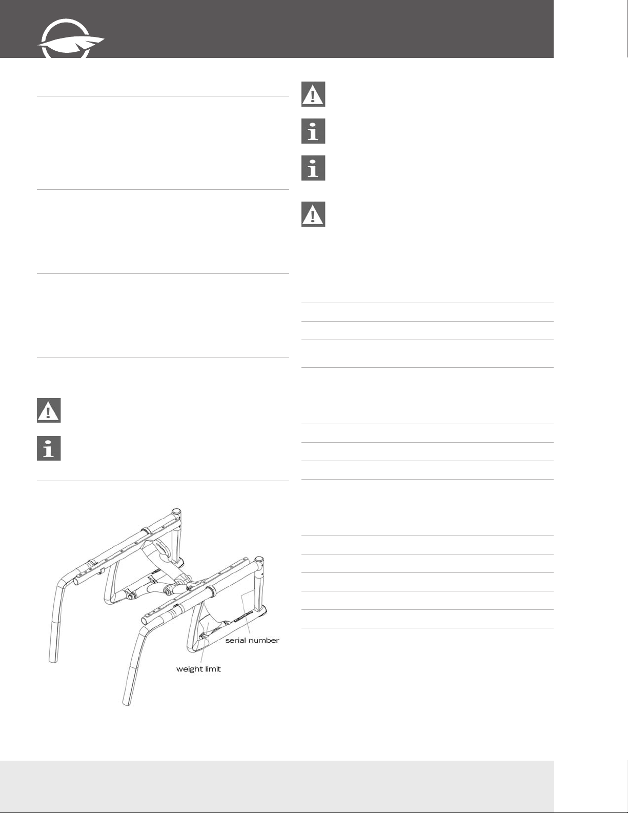
4.3 Label Locations
5.2 Dimensions
Width 14’’ to 20’’
Depth 14’’ to 20’’
Front seat-to-floor height 13 ½’’ to 22 ¼’’
Rear seat-to-floor height 12 ½’’ to 20’’
5.3 Adjustability
Upholstery Tension adjustable bolt on
Back height 9’’ to 21’’
Adjustable angle from 70° to 110°
Footrest removable and swing away
Camber 0°, 3°, 6°
Centre of gravity from ½” to 4 ½” + amputee axle
plate option
Do not remove or alter any labels on the wheelchair. If the label
is damaged, replace it with a new one.
6
T (450) 588-6555 - 1 866 650-6555 F (450) 588-0200
Page 7

EDITION - V 1.0
User
Manual
6. Safety
6.1 Periodic Checklist
See related appendix (section 14).
6.2 Weight Limitation
The VELOCE wheelchair has a weight limit of 220 lbs (100.0
kg). The specified weight capacity includes: both the rider and
any luggage. A user with a 10lb backpack, for example, should
not exceed a weight of 210 lbs. It is of utmost importance that
the total weight be below the above specified capacity.
The wheelchair is designed to support only one person. Please
do not stand up on the footrests.
Motion Composites is not responsible for any damages or
injuries caused by the misuse of this wheelchair.
6.3 Weight Training and Sporting Activities
This wheelchair was not designed or tested as a weight training
apparatus. Do not attempt to use this wheelchair in weight
training. The warranty shall be void if the wheelchair has been
used for any weight training purposes.
This wheelchair is not intended to be used during sporting
activities.
Should you make any adjustments, repairs or do any
servicing, ensure that all fasteners are tightly secured
before use.
Exceeding the specified weight limit could damage the
wheelchair and/or cause severe injuries.
This wheelchair was designed to be tailored to the
dimensions of its owner and as such should only be
used by its owner unless a qualified specialist,
approved by Motion Composites, has readjusted it.
8. Riding your VELOCE
Should you make any adjustments, make sure to
familiarize yourself with the wheelchair movements
before removing the anti-tippers.
The wheelchair should be dried with a cloth
immediately after being exposed to water.
8.1.1 To reduce the risk of accident
We recommend that you review safe wheelchair use with your
physician prior to using this equipment.
Take the time to read the instructions in this manual to ensure
that you feel comfortable using the wheelchair without
assistance.
Always be aware of hazards.
Always use anti-tippers.
8.1.2 Environmental Conditions
The VELOCE was designed to be used on hard and plane
surfaces like asphalt, concrete, and indoor flooring such as
carpeting.
Beware that the manoeuvrability of the wheelchair is
significantly affected by different outside conditions such as
sand, mud, rain, snow and rough surfaces. If you use your
wheelchair in these conditions, it is recommended that you have
it frequently serviced.
Be careful when using your wheelchair on wet or slippery
surfaces.
Exposure to water or excessive moisture can be damaging and
may even cause the wheelchair to corrode over the long-term.
Do not leave your wheelchair in humid environments such as
the bathroom (e.g. while taking a shower).
7. Tutorial
Please find many tutorial and maintenance tips on our YouTube
page at : http://www.youtube.com/heliowheelchair
Do not use your wheelchair in the shower, pool, or other water
situations.
8.1.3 Caregivers
• Never use removable parts (e.g. armrests, footrests) to push
the wheelchair and never use lifting supports since they could
cause injuries or damage.
• Ensure that the wheelchair is equipped with push handles and
that its grips are securely in place.
• Turn anti-tipping devices upwards or remove them to avoid
tripping.
• Should you need to leave the wheelchair user unattended,
engage the wheel locks and place the anti-tipping devices
back in the downward position.
• Ask an experienced caregiver to explain safe assistance
methods to you.
• Ensure ongoing communication between you and the
wheelchair user as to avoid any kind of confusion.
• Maintain proper posture to tilt or lift the wheelchair; keep your
back straight and bend at the knees.
• Instruct the wheelchair user to lean his/her back when you are
tilting the wheelchair.
7
Page 8
veloce
8.2 Riding your wheelchair
Various adjustments of your wheelchair (seat height/
depth/system, back angle, rear & front wheels camber/
size/position, position of the front riggings) could affect
the center of gravity. The adjustments should be
performed by a professional and the wheelchair user
should be aware that the stability could be affected by
these adjustments.
Do not tilt the wheelchair or perform a wheelie without
assistance if you are a new wheelchair user.
8.2.1 Balance point
It is important to begin by learning all of the specific
characteristics of your wheelchair. Ask a health professional
to explain them to you. Carrying a backpack will affect the
balance point of your wheelchair. Be aware of resulting
handling factors in relation to your body position, posture or
weight distribution. The center of gravity is affected by the
angle of the wheelchair on a ramp or slope. This can be felt in
forward and backward as well as side to side movements.
Make sure to review the different riding techniques prior to
using the wheelchair. Use anti-tippers until you are skilled at
riding your wheelchair in any situation.
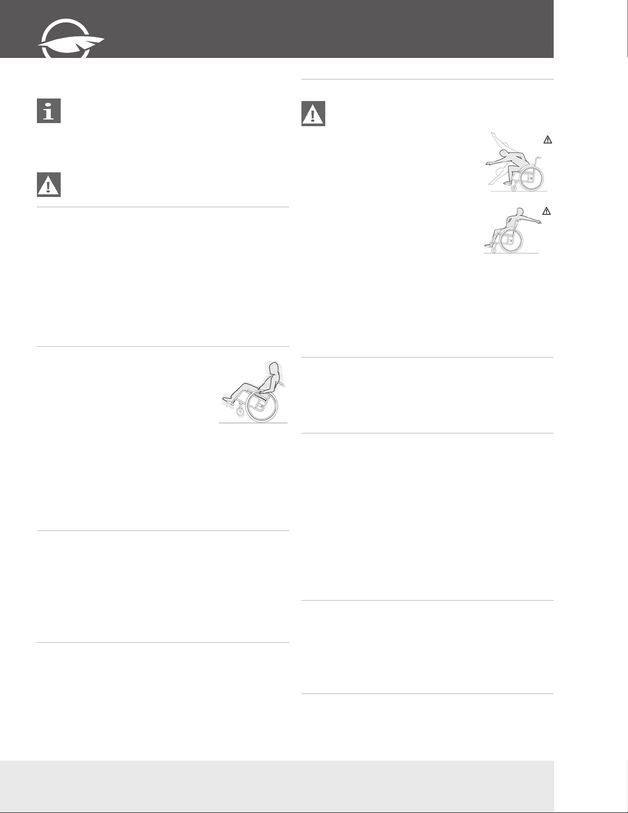
8.2.2 Wheelies
Wheelies involve lifting the front casters off
the ground while maintaining balance on the
rear wheels. Performing this manoeuvre,
while allowing you to easily avoid obstacles,
may result in serious injury. Consult your
doctor before doing wheelies.
Ask for assistance while doing wheelies. The assistant should
be behind the wheelchair to grab the grips and prevent any
potential falls. To perform a wheelie, grab the front part of
the hand rims and make a quick backward movement with
the rear wheels. Make an immediate fast forward thrust and
the front casters will lift off the ground. Maintain the balance
point by making small movements on the hand rims. Once you
feel comfortable with maintaining your balance point while
performing this manoeuvre, you no longer need any assistance.
8.2.3 Transferring
Rotate the front casters forward to enhance stability.
Place the wheelchair as close to your transfer location as
possible. Engage wheel locks. Position yourself as far back
as possible when transferring weight to reduce risk of tipping
forward. If you have good upper body strength, balance and
agility, you may be able to perform transfers independently.
Rotate or remove footrests if at all possible as to avoid putting
weight on them. If possible, make use of a transfer board.
8.2.4 Getting Dressed
When dressing or undressing on the wheelchair, rotate the front
casters forward and lock anti-tippers in the lower position.
If your wheelchair is not equipped with anti-tippers, back it
against a wall and lock the rear wheels.
8.2.5 Reaching/Leaning/Bending
The balance point may shift when you are putting on
clothes and/or reaching for objects while sitting in the
wheelchair.
If at all possible, use a reaching device
or ask for assistance when reaching for
objects.
Move the wheelchair as close as possible to
the required object.
Rotate the casters as far forward as
possible from the rear wheels.
Never reach for objects between your legs,
but rather position yourself to the side of
these objects.
Do no shift your weight sideways, but
rather rise up from the seat or move
forward in the seat.
Always use both hands and grab the
opposite side wheel or armrest if you are capable of reaching
sideways.
Never reach to the rear of the wheelchair unless it is equipped
with anti-tippers
Never reach for objects over the seat back: reach only as far
as your arm naturally extends without moving on the seat.
Do not lock the rear wheels if you are reaching backwards.
Avoid putting pressure on the footrests.
8.2.6 Moving backwards
Lock anti-tippers in lower position.
Move slowly: the wheelchair is designed to provide you with
more stability when moving forward.
Look around as often as possible to avoid obstacles in your
path.
8.2.7 Ramps, Slopes & Side Hills
Do not ride hills with an elevation slope of more than 10% (one
foot elevation change for every 10 feet).
Try to move straight up or down the slope.
Avoid turning on a downhill slope.
Stay in the center of sidewalks and ensure that there is enough
space for the wheels.
Avoid stopping on slopes and never use the wheel locks to slow
yourself on a downhill slope. Maintain your speed by holding the
hand rims.
Do not ride on wet or slippery surfaces. Be cautious for
changes in terrain height or stairs at the end of a slope (front
casters may lock from simply hitting a small bump).
Ask for help should any situations arise.
Incline yourself while moving down a slope as to adjust your
centre of gravity.
8.2.8 Obstacles
Always look for obstacles or road hazards (potholes, broken
surfaces, etc.). Clear your own environment (work, home)
of any obstacles. Never use objects (furniture, ramps, and
doorknobs) to push yourself out of the wheelchair.
Lean your upper body slightly forward as you move up an
obstacle. Do the reverse while moving down an obstacle. Keep
both hands on the hand rims while passing over the obstacle.
8.2.9 Curbs and Steps
Remove or rotate the anti-tippers upwards to go up or down a
curb or step. Move straight up and down and never angle the
wheels.
8
T (450) 588-6555 - 1 866 650-6555 F (450) 588-0200
Page 9
EDITION - V 1.0
User
Manual
8.2.10 Moving with Assistance
Caregivers should read the “Caregiver” section of this manual.
1 - Going up a curb or step
• Place yourself behind the wheelchair.
• Go forward and tilt the wheelchair with the rear wheels by
making sure that the front casters do not touch the curb or
the step.
• Once the front wheels are elevated and you have passed the
obstacle, put them back on the ground and continue pushing
the wheelchair.
2 - Going down a curb or step
• Place yourself behind the wheelchair.
• Before reaching the edge of the curb
or step, change the direction of the
wheelchair by turning it around the
obstacle.
• Pull the wheelchair while going down the
curb or step.
• Pull the wheelchair until the rear wheels reach the edge of
the curb or step; the rear wheels must slowly touch the lower
level.
• Pull the wheelchair backward until the front wheels touch the
edge and then lower the front back to the ground.
• Return the wheelchair to its normal driving position.
8.2.11 Moving without assistance
For any information regarding balance, please refer to the
sections entitled “Balance point” and “Wheelies”.
• Ensure that you are able to do a wheelie and that you are
strong enough to execute this weight transfer.
• Do not attempt to go up a step or curb over 4 inches high
without assistance.
• Go down as smoothly as possible to avoid any damage.
9. How to use your VELOCE
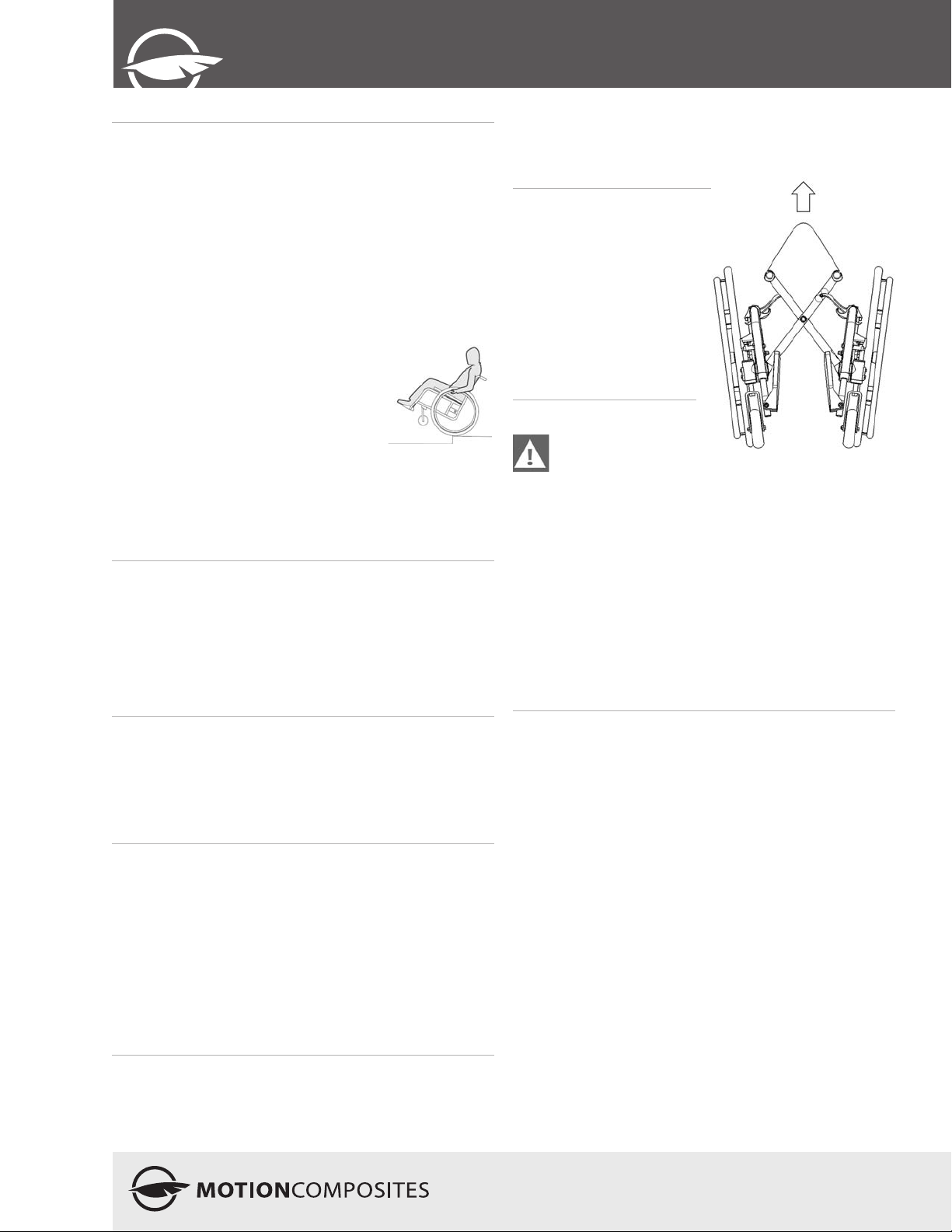
9.1 Folding & Unfolding
9.1.1 Folding
• Rotate front riggings
forward until they lock.
• Flip up the footplates.
• Remove the seat cushion.
• Lift the handle on the seat
upholstery.
• Pull the wheels towards
each other.
9.1.2 Unfolding
When unfolding the
wheelchair, be careful
not to put your fingers between the pivot links, or under
the seat rails. Always push or pull on the seat
upholstery. Make sure the wheelchair is fully opened
before transferring or sitting.
• Tilt the wheelchair towards you; make sure the opposite
wheels are off the ground.
• Push the edge of the seat upholstery towards you until it
closes properly.
• Press downwards on both seat rails in order to engage the
lock mechanism of the wheelchair. It is necessary to push
down on the middle of the seat rails to make sure that they
are correctly positioned in the seat rail supports. You will feel
a click between frame components
8.2.12 Stairs
Use an elevator wherever possible.
Ask for help from two people to move the wheelchair up or
down stairs (the caregivers should read the “Caregiver” section
of this manual).
Fasten your seat belt when being lifted in the wheelchair.
Going up or down the stairs
Tilt the wheelchair back to its tipping point.
When going up, bring the wheelchair backwards until the rear
wheels touch the first step.
When going down, bring the wheelchair forward to the edge of
the stairway.
Pull up or lower the wheelchair to the next step: one assistant
should be behind you and the other in front of you.
Repeat the same movements for every step until you reach the
end of the stairway.
Lower the front of the wheelchair to the ground once the front
wheels are not touching the floor.
8.2.13 Escalators
Under no circumstances should this wheelchair be used on an
escalator, not even with the help of an attendant. This could
cause severe injuries.
9
Page 10
veloce
9.2 Wheel Locks
Never use wheel locks to stop wheelchair movement.
WHEEL LOCKS ARE NOT BRAKES. Make sure the
surface is not slippery as the wheelchair could move
even though the wheel locks are engaged.
Ensure that brake locks imbed at least 1/8” into the tire
rubber when chair is in locked position.
Ensure the wheelchair is stable and locked with wheel locks.
• To engage the locks, push wheel
lock handle forward (for pushto-lock type) or pull wheel lock
backward (for pull-to-lock type)
until the lock is fully engaged.
• To release the locks, pull wheel
lock handle backward (for
push-to-lock type) or push wheel
lock handle forward (for pull-tolock type) until the lock is fully
disengaged.
9.3 Footrest
• When transferring, avoid putting weight on the footrest and be
careful not to stand behind the footrest.
• Never use footplates to lift the wheelchair.
• Only use non-detachable parts to lift the wheelchair.
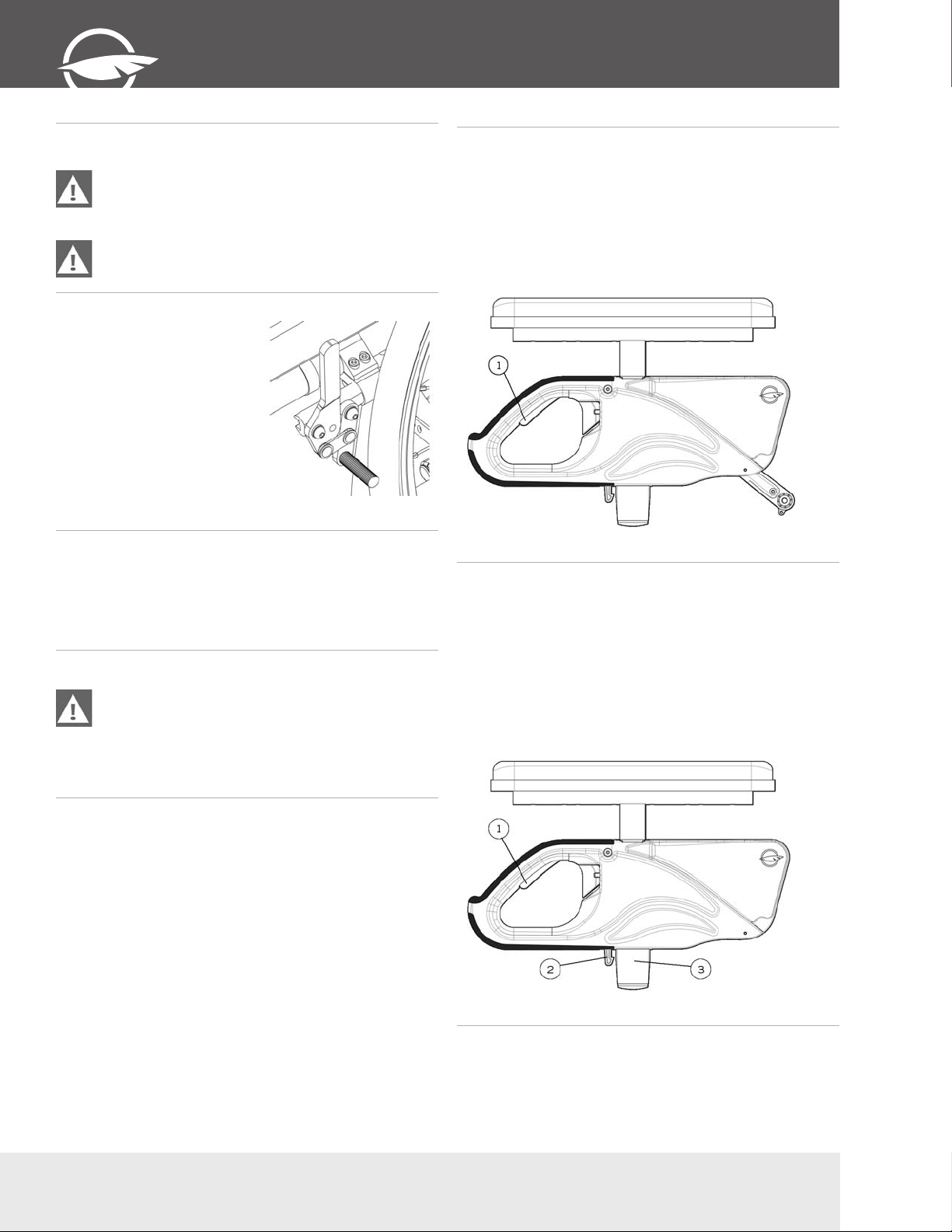
9.4.1 Flip-back armrests
To lift the armrests:
• Pull lever (1) upwards to release the system.
• Rotate the armrest all the way up and down.
To reinstall the armrests in closed position:
• Rotate the armrests downward until the front slide plate
enters in the armrest receiver and snaps into place.
• Make sure the locking lever is engaged to avoid any
movement.
9.4.2 Removable T armrests
To remove the armrests:
• Pull lever (1) upwards to release the system.
• Pull the armrest all the way up.
9.4 Armrests
Ensure that armrests are securely locked into arm
sockets and armrest release buttons are locked into
place prior to using the wheelchair.
• Never lift the wheelchair by holding the armrests.
• Use only non-detachable parts for lifting.
To reinstall the armrests:
• Bring the armrests downward until the slide (3) enters in the
armrest receiver (not pictured in diagram) and snaps into
place.
• Make sure locking lever (2) is engaged to avoid any
movement.
10
T (450) 588-6555 - 1 866 650-6555 F (450) 588-0200
Page 11
EDITION - V 1.0
User
Manual
9.4.3 Swing-Away Armrests
To remove the armrests from the
wheelchair:
• Lift them slightly to release the armrest
(1).
• Rotate them outwards.
• To reinstall the armrests, rotate them back
in until they set into place (1).
9.5 Seat belts
Use positioning belts ONLY to help support the rider’s
posture. Improper use of these belts may cause severe
injuries to the rider.
Make sure the rider does not slide down in the
wheelchair seat. If this occurs, the rider may suffer
chest compression or suffocate due to pressure from
the belts.
Never use belts as a motor vehicle restraint.
9.6 Anti-Tipper
Motion Composites
strongly recommends the
use of anti-tippers
Anti-tippers were designed to
prevent falls from the wheelchair.
• To remove or rotate the antitippers up, push the release
button and pull out or rotate the
anti-tippers.
• To replace the anti-tippers, press
the release button and insert
them into the frame until they
snap into position.
9.7 Rear Wheels
9.7.1 Quick-release axles
• To remove the rear wheels, push the button in the center of
the wheel’s hub and pull the wheels off.
• To reinstall the rear wheels on the wheelchair, push the button
of the quick-release axles, insert the axle into the wheelchair
axle bushing and release the button
• Always make sure that the quick release detent balls (2)
extend beyond the axle bushing for a secure lock.
• The seatbelt should be used at all times in accordance with
instructions.
• There should be approximately one hand width of space
between the seat belt and thigh; do not exceed this amount
of space.
• Ensure that the seat belt is properly fastened as to avoid
serious injury.
• In case of emergency, ensure that seat belt can be easily
unfastened.
9.5.1 Auto buckle and aircraft buckle seatbelts
• To fasten your seatbelt, insert the clip into the buckle until it
snaps.
• Make sure the belt is securely fastened.
• To unfasten your seat belt, lift the flap on the aircraft buckle
seatbelt or push the button on the auto buckle seatbelt.
• To adjust your seat belt, pull each strap towards the opposite
side until you get the desired tension and keep the buckle
centered.
9.5.2 Velcro Belt
• To fasten your seatbelt, insert the long side of the seatbelt
into the buckle on the other side.
• Apply pressure on the belt for a firm grip of the velcro.
9.7.2 Fixed axles
• To remove the rear wheels: unscrew the bolt located inside
the wheelchair axle bushing and pull out the wheel.
• To reinstall the rear wheels on the wheelchair: insert the
threaded axles in the axle bushing.
• Tighten the bolt and make sure that the wheel is still turning
without any restrictions.
9.8 Seat slings
• Seat slings are not intended to be used as a seating surface.
Always use a cushion.
• Ensure that the sling is in good condition (e.g. no fraying, no
wear and no tears).
11
Page 12
veloce
10. Adjustments and
maintenance of your
VELOCE
10.1 Service
Refer to your dealer for service. A complete and updated list of
service providers can be found on our website.
10.2 Replacement Parts
Ordering information:
Consult our website to download the parts manual and view
ordering information.
Please contact us at:
Motion Composites Inc.
519 J-Oswald Forest, suite 101
Saint-Roch-de-l’Achigan, Quebec
J0K 3H0 Canada
Phone: 1-866-650-6555
Fax: (450) 588-0200
[email protected]
www.motioncomposites.com
10.3 Tools needed
The VELOCE was designed to be serviced with regular
tools. All screws and bolts are standard and can be
adjusted with a wrench, socket wrench, or Allen key.
Motion Composites does not recommend the use of any
power tools to tighten screws on this wheelchair. Final
tightening should be done manually.
10.5 Backrest
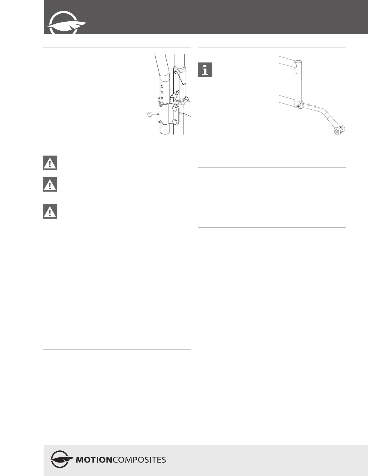
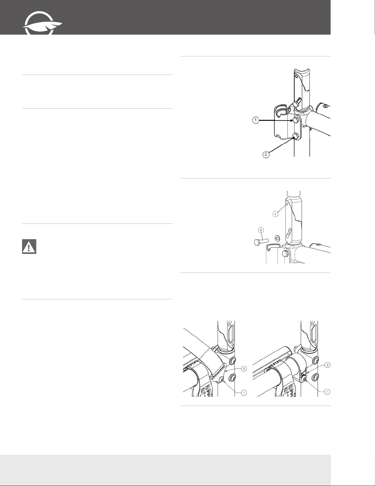
10.5.1 Removing/Installing the Back Canes
• Loosen the top bolts (1) and
(2), which are also used to
support the armrest socket
(Swing Away and Flip Back
armrest).
• Slide down the back post to
remove it from the tube.
• Reinstall the back post
in the reverse order and
tighten screws snugly.
• Tighten bolts (1) and (2)
firmly.
• Wheelchairs equipped with
Flip Back armrests; tighten
screw (1) while paying
special attention to the
force needed to flip back
the armrest.
10.5.2 Adjusting the Back Angle
• Loosen screw (1) and
remove screw (2) from the
levelling device.
• Adjust to desired angle by
sliding the mechanism.
• Reinstall screw (2) and
tighten both screws to fit
snugly.
10.5.3 Removing/Installing the seat belt
10.4 General maintenance
10.4.1 Tire pressure
• Check tire pressure with a tire gauge.
• Inflate if pressure is below recommended amount as labelled
on the sidewall.
• Do not inflate tire over recommended pressure.
• Over inflation could result in tire failure and injury.
• Under inflation could result in a flat tire.
10.4.2 Cleaning your wheelchair
• Use a soft clean cloth with soap and water to clean your
wheelchair.
• Rinse and dry the wheelchair adequately.
• Do not use abrasive cleaners.
• Do not use a pressure cleaner.
12
• Remove Screw (1) in order to remove the seat belt clamp (2)
that is attached to the belt
• Reinstall screw (1) directly on the frame clamp (3)
• Tighten screw (1) until it is properly tightened.
• Repeat the same steps on the other side
T (450) 588-6555 - 1 866 650-6555 F (450) 588-0200
Page 13
EDITION - V 1.0
User
Manual
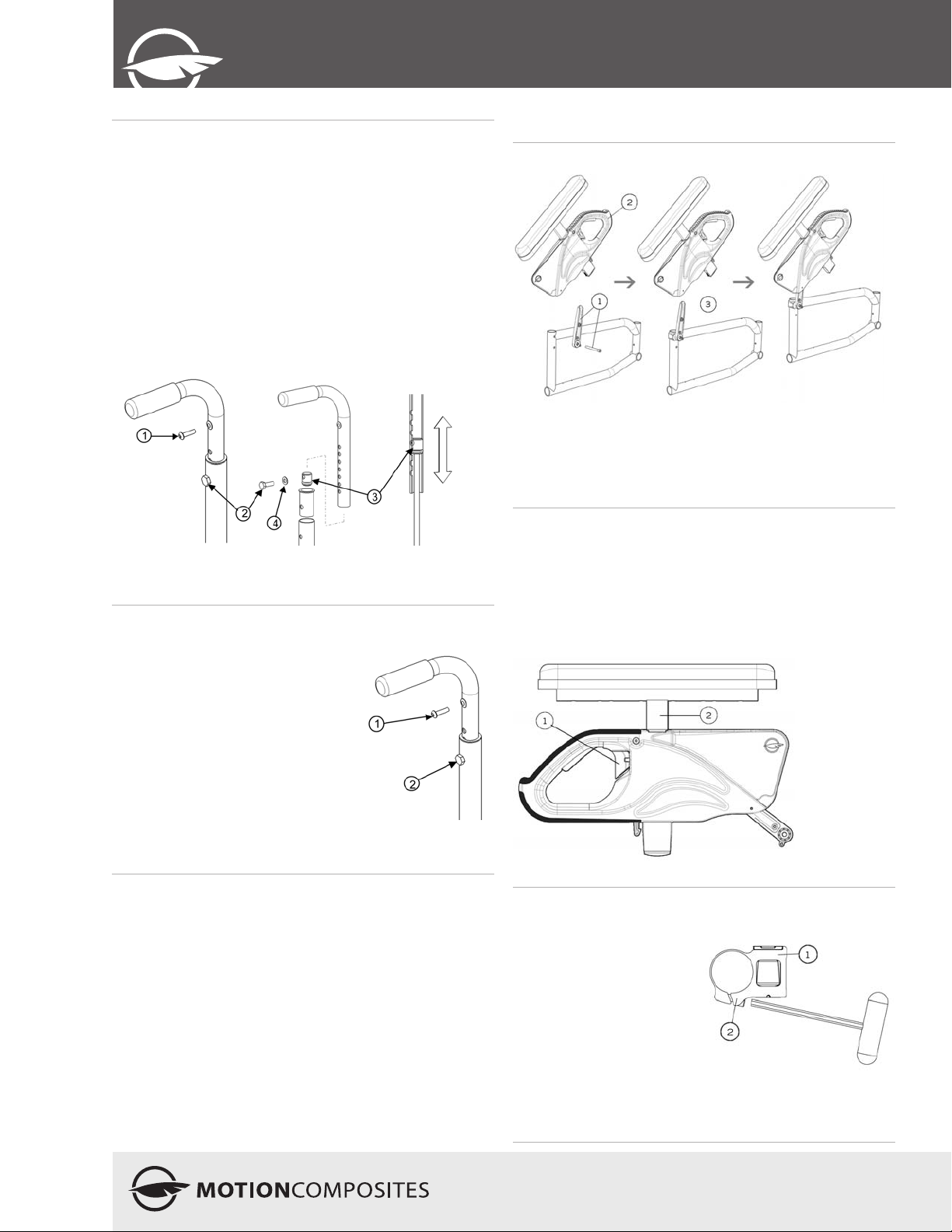
10.5.4 Adjusting the Backrest Height
• Loosen the screw (1) that holds the back upholstery.
• Pull backrest upholstery down several centimetres in order to
access screw (2) that holds the push handle.
• Remove screw (2) and the backrest handle.
• To adjust the backrest height, with the help of a threaded rod
(¼”-20), move the dowel nut (3), which is located inside the
handle.
• Once this step is completed, use screw (2) to hold the dowel
nut (3) while removing the threaded rod.
• Remove screw (2) and reinstall backrest handle.
• Align screw (2) with the mounting hole.
• Reinstall and tighten screw (2) and the washer.
• Repeat the same steps on the other side.
• Reinstall the backrest upholstery with screw (1) and tighten to
fit snugly.
Seat
10.5.5 Installing/Removing Standard Seat
Upholstery
10.6 Armrest
10.6.1 Installing Flip-back Armrests
• Insert the flip-back pivot (1) and screw it in place, making sure
it stays in place but can rotate easily.
• Insert the armrest (2) on the flipback pivot than rotate it until
it clicks with the front clamp (for clamp installation, see 10.6.3
installing removable T-armrests).
10.6.2 Adjusting the height of Flip-back armrests
• Flip lever (1) left or right to unlock the armrest.
• To adjust height, slide the upper part of the armrest into the
lower part.
• Adjust the structure (2) at the desired height.
• Flip the lever back to the closed position.
• Make sure the armrest clicks in place for complete
securement.
• Remove screw (1) that holds the back
upholstery.
• Pull backrest upholstery down several
centimetres to gain access to screw (2),
which holds the push handle.
• Remove screw (2) and then remove the
backrest handle.
• Remove or install back upholstery.
• Once, the new back upholstery is
installed, reinstall the handles by aligning
them with the mounting holes.
• Reinstall and tighten screw (2) firmly.
• Install back upholstery at and fix it firmly
with screw (1) on each back cane.
10.6.3 Installing removable T-armrests and rigid
sideguard
• Install clamp (1) on the
upper tube of the frame at a
distance of 160mm (6 1/4”)
from the rear tube of the
frame.
• Slightly tighten screws (2) to
allow the clamp to rotate.
• Insert armrest or sideguard
into clamp (1).
• Rotate clamp (1) until the
sideguard is perpendicular to
the seat.
• Tighten screws (2) firmly.
13
Page 14
veloce
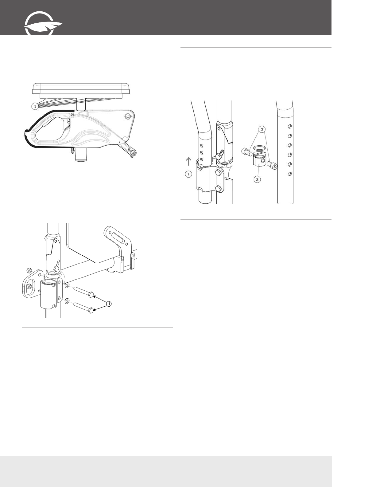
10.6.4 Replacing Armrest Pad
• Remove screws (1) located under pad (through the tube).
• Replace with new armrest pad.
• Reinstall screws (1) and tighten firmly.
10.6.5 Installing the Swing-away Armrest
receiver
• Remove the two bolts (1).
• Align the armrest receiver with the mounting holes of the
frame and of the transit securement anchor.
• Reinstall the bolts and tighten firmly.
10.6.6 Adjusting Swing-away Armrest height
• Pull the armrest out of the receiver (1).
• Remove screws (2).
• Inside the armrest tube, slide the dowel nut with a long
screwdriver at the desired height (3)
• Reinstall screws (2).
• Reinsert armrest in receiver.
14
T (450) 588-6555 - 1 866 650-6555 F (450) 588-0200
Page 15
EDITION - V 1.0
User
Manual
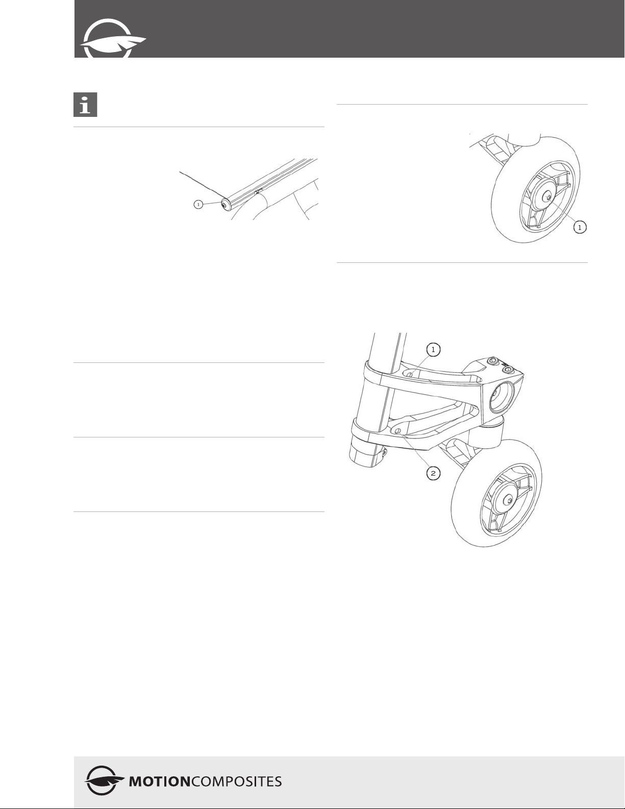
10.8 Seat
It may be difficult to unfold the wheelchair if the seat
upholstery has been installed too tight.
10.8.1 Replacing Seat Upholstery
• Remove end cap (1).
• Slide in new seat
upholstery.
• Reinstall end cap (1)
• Adjust tension with the
velcro located under the
seat upholstery.
• Fully open the wheelchair and make sure the upholstery is
tight. The seat rails must be snapping easily in the seat rail
supports.
• Firmly tighten all screws on the seat rails.
10.9 Seat-to-floor height
Any modification to the seat-to-floor height involves adjustment
of anti-tippers, front caster angle, and rear wheel toe-in/toe-out
if equipped with 3° or 6° camber. It is important to do these
adjustments before using the wheelchair as to reduce risk of
injury.
10.9.1 Changing the Front Seat-to-Floor Height
10.10 Front casters, forks and
fork stem assemblies
10.10.1 Removing/Installing/Repositioning the
Front Wheels
• Loosen and unscrew (1).
• Remove, install or reposition
the front castor.
• Tighten screw (1) firmly.
10.10.2 Removing/Installing the caster housing
• Remove screw (1).
• Remove screw (2).
• Slide the caster housing out of the frame.
To change the front seat-to-floor height, you can do one of the
following:
• Install the front caster in a different hole on the fork
• Install different caster size.
• Change the stem bold length (Standard, +1” and +2” available)
10.9.2 Changing Rear Seat-to-Floor Height
To change the rear seat-to-floor height, you do one of the
following:
• Install the rear wheel axle bushing in a different position along
the mounting plate.
• Install different sized rear wheels.
10.9.3 Changing Front & Rear Seat-to-Floor
Height
To change the front and rear seat-to-floor height simultaneously,
you can:
• Use another seat cushion with a different thickness.
*To change the stem bolt or to service the bearings, always
remove the caster housing from the frame
15
Page 16
veloce
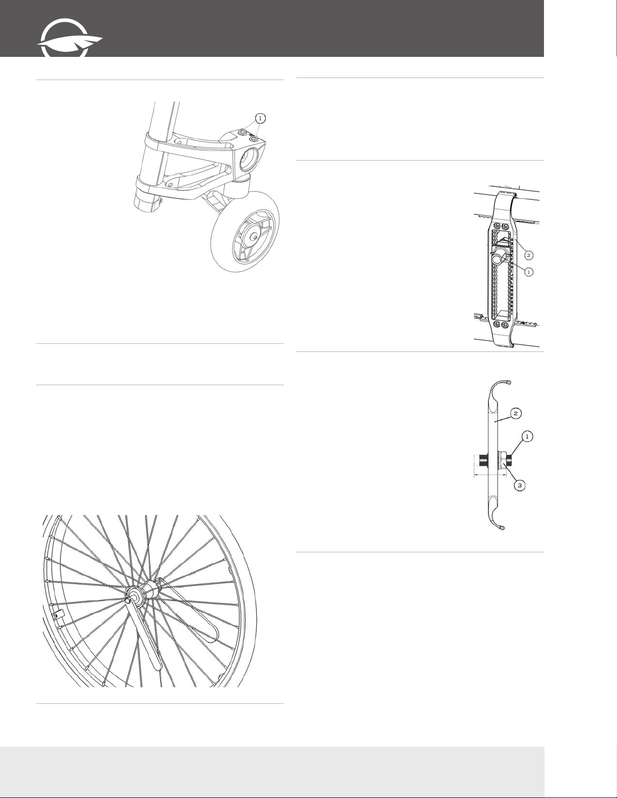
10.10.3 Adjusting the castor housing angle
• All four wheels should
be touching the floor.
• Use a set square and
place it on the ground
and along the caster
housing.
• The housing should
be parallel to the set
square.
• If the housing is
not parallel to the
set square, loosen
screws (1)
• Rotate the caster
housing to adjust the
angle.
• Tighten screws
(1). This will hold
the caster housing
position.
• Check again that
the caster housing is
perpendicular to the
ground using the set
square.
10.11 Rear wheels
10.11.1 Adjusting Quick-Release Axles
• Remove the rear wheel from the wheelchair and then remove
the axle from the wheel.
• Behind the quick release button, there is a nut that adjust the
length of the axle.
• Hold the axle with a wrench at the other end (near the detent
balls) and turn the nut behind the quick release button to
change the length of the axle.
• Reinstall the quick release in the wheel and into the axle
bushing on the wheelchair
• Quick release detent balls should extend beyond the axle
bushing for a secure lock.
10.11.2 Replacing/Adjusting hand rims
• Use a plastic tire removal tool to take off the tire.
• Remove all nuts inside the rim.
• Replace the handrim with a new one and align the mounting
holes.
• Reinstall and tighten the nuts firmly.
• Reinstall the tire on the rim.
10.11.3 Adjusting the rear axle height
• Loosen the two nuts holding the axle
bushing.
• Move axle bushing along (1) mounting
plate (2).
• Reinstall the bushing in the desired
mounting hole.
10.11.4 Adjusting rear wheel spacing
The rear wheels can be adjusted
laterally by repositioning axle bushing
(1) on mounting plate (2).
• Loosen nuts (3) on the axle bushing
(1).
• Turn them in the desired direction to
adjust the spacing.
• Firmly tighten the nuts (3).
16
T (450) 588-6555 - 1 866 650-6555 F (450) 588-0200
Page 17
EDITION - V 1.0
User
Manual
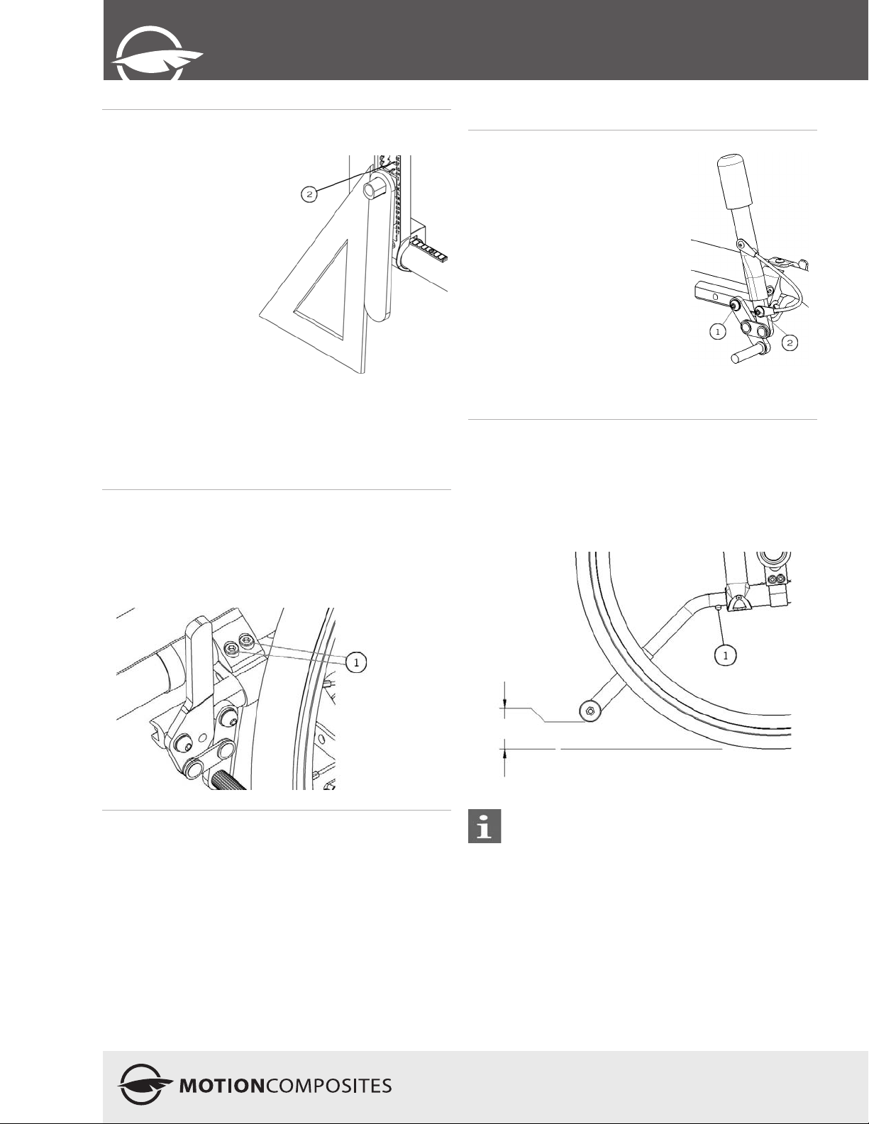
10.11.5 Adjusting the toe-in/toe-out with rear
wheel camber.
• Remove the rear wheels.
• Maintain the wheelchair
on a horizontal plane
with the support of the
three other wheels.
• Loosen nuts (2) while
keeping a bit of tension.
• Put the camber
adjustment tool on the
axle bushing
• Use a set square and
rotate the axle bushing
so that the tool is parallel
to the set square (and
perpendicular to the
ground)
• With one hand, hold the
tool and the mounting
plate together to keep the setting.
• With the other hand, use a ratchet to tighten firmly the nut (2)
facing inside the wheelchair.
10.12 Wheel Locks
10.12.1 Replacing/Adjusting the Wheel Locks
• Loosen screws (1).
• Slide the lock to the desired position.
• Tighten screws (1) to a snug fit. Final tightening should be
done manually.
• Once engaged, the lock should embed 3 mm into the tire.
10.13 Extension brakes
10.13.1 Replacing/Adjusting the brake extension
• Loosen screw (1).
• Align eyelet (2) with the
mounting hole.
• Re-tighten screw (1) on the
brake lever.
10.14 Anti-tippers
10.14.1 Adjusting the Height of the Anti-tippers
The anti-tippers should be between 1½ and 2 ¾ inches (40
to 70 mm) off the ground. Improper spacing may result in
wheelchair hang ups over obstacles or not preventing the
wheelchair from tipping.
• Press the push-button and slide anti-tippers extensions to
desired length.
• Ensure the button snaps back into place.
If you are unable to adjust the anti-tippers to the proper
height, contact your Motion Composites dealer to
replace your anti-tipper for another size.
17
Page 18
veloce
10.15. Headrest Kit and
Headrest Support
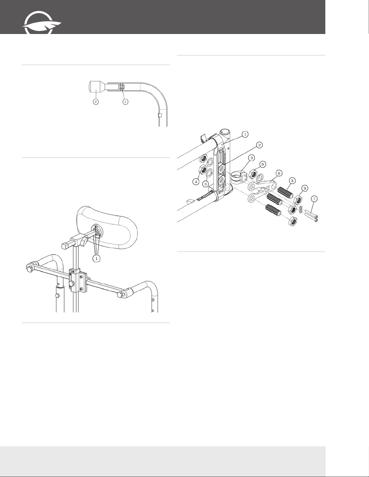
10.15.1 Installing a headrest support
• Cut the end of the push-
handle with a knife in
order to be able to see
the inside of the push
handle.
• Insert a 1/4”-20 grip
nut (1) with the grip nut
insertion tool (2) inside
the handle (40 mm).
• Install fastening device
of the headrest support
by tightening it in the
1/4”-20 roll pin.
10.15.2 Installing Headrest Kit
• Once the headrest support is installed, insert the adjustable
headrest into the horizontal receiver.
• Install headrest on the ball pivot and tighten the three screws
(1).
• Once the adjustment is completed, firmly tighten all parts.
11.16 Amputee extention plate
10.16.1 Installing an amputee plate
• Install mounting plate (1) by closing the clamps around the
frame.
• Insert a second axle receiver (2) on the axle plate
• Install the back clamp (3) onto the rear of the frame.
• Insert both bolts (4) and washers (5) through the amputee
axle plate (6) to secure it in place
• Insert two screws (7) into amputee axle plate through the
mounting clamp and tighten.
• Insert axle bushing (8) through the amputee plate and tighten
nuts (9).
18
T (450) 588-6555 - 1 866 650-6555 F (450) 588-0200
Page 19
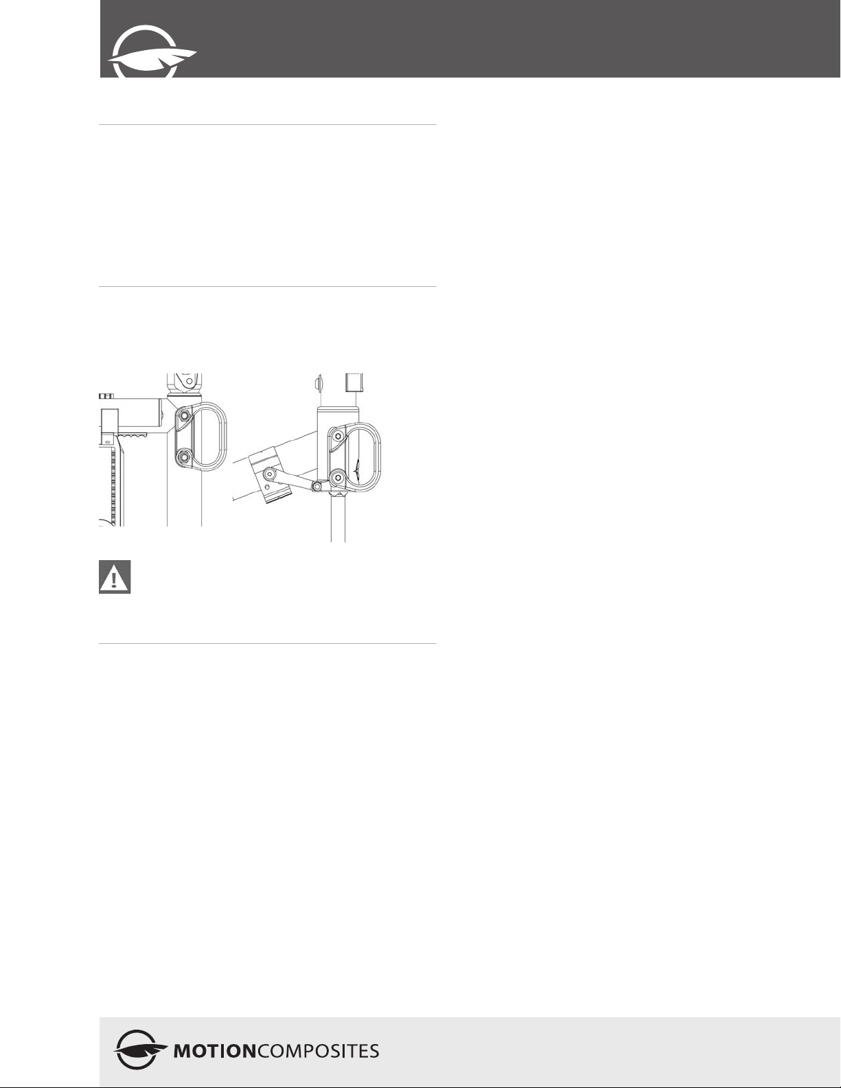
EDITION - V 1.0
User
Manual
11 Using a paratransit service
11.1 About paratransit vehicles
It is recommended that wheelchair occupants remain seated
with seatbelt fastened while traveling in a vehicle designed
to transport passengers in wheelchairs. Ensure that your
wheelchair is securely fastened in the wheelchair restraints:
restraints used should be approved and meet the safety
requirements in effect.
The wheelchair seatbelt should never been used as a safety
belt when you are sitting in a paratransit vehicle.
11.2 Wheelchair restraints in paratransit vehicles
Always use proper restraints to secure your VELOCE
wheelchair in a motor vehicle. The restraints are identified by
the following symbol:
Never hook the transport tie-downs directly to the
wheelchair frame. This may damage the frame and void
the warranty. To avoid risk of injuries, remove all
objects or accessories from the wheelchair and store
them securely in the paratransit vehicle.
19
Page 20

veloce
12 Motion Composites limited
warranty
A. Frame – 5 years
Motion Composites warrants the wheelchair frame and cross
braces against defects in materials and workmanship for five
years from the date of purchase.
B. Components – one year
Motion Composites warrants all Motion Composites-made
components against defects in materials and workmanship for
one (1) year from the date of purchase, except for parts listed
below.
C. Limitations and exclusions
1 Motion Composites covers the following items for 30 days:
• tires and tubes for front or rear wheels, upholstery (including
cushions, seat slings, armrest upholstery) and push-handle
grips;
2
This warranty does not cover:
• damage arising from normal wear and tear or from other
circumstances beyond Motion Composites’ control; or
3
The foregoing warranty shall not apply if:
• the original Motion Composites serial number tag has been
removed, altered or defaced; or
• the wheelchair has been subjected to negligence, accident,
improper maintenance, storage or operation as required by
your Motion Composites Owners Manual, commercial or
institutional use, misuse or abuse, including, but not limited
to, exceeding the maximum weight capacity of 250 pounds
(113,4 kg); or
D. Our responsibility
Motion Composites’ sole obligation and your exclusive remedy
under this warranty shall be limited to such repair and/or
replacement.
E. Warranty Service
If your wheelchair requires warranty service, please contact
an authorized Motion Composites Dealer in Canada or an
authorized international distributor. In the event of a defect in
material or workmanship, the Dealer or Distributor must obtain
a return authorization (RA) number from Motion Composites.
Motion Composites issues RA numbers only to authorized
Motion Composites Dealers and Distributors. In the event
that you do not receive satisfactory warranty service, please
write directly to Motion Composites Customer Service at 519
J-Oswald Forest, suite 101, Saint-Roch-de-l’Achigan, Qc, J0K
3H0 or send an email at: [email protected]. Do
not return products to our factory without our prior consent.
CONSUMER NOTICE
1 The foregoing warranty is exclusive, and in lieu of all other
express warranties, whether written or oral, express or
implied. Motion Composites shall not be liable for any
consequential or incidental damages whatsoever. By
registering your Motion Composites wheelchair, you will be
deemed to agree with all provisions of this warranty.
It is forbidden to alter or extend the foregoing
2
express warranty or to waive any of the limitations or
exclusions.
• the wheelchair has been damaged by improper repairs or
repairs made to any component without the express written
consent of Motion Composites; or
• the wheelchair has been modified without Motion
Composites’ express written consent, including, but not
limited to, modification through the use of unauthorized
parts or attachments; or
• the wheelchair has been used as a weight training
apparatus; or
• the wheelchair’s Transit Tie-Down System (TTDS) has been
misused; if TTDS is not attached to the four tarpaulin bows
identified and installed by Motion Composites.
4
This warranty is extended only to the original consumer
purchasers of Motion Composites’ product.
20
T (450) 588-6555 - 1 866 650-6555 F (450) 588-0200
Page 21

13 Notes
EDITION - V 1.0
User
Manual
21
Page 22

veloce
14. Safety Inspection Checklist
Action Frequency
At every use Weekly Monthly Twice-yearly Yearly
Make sure wheelchair rolls
easily and straight. √
Check for vibrations, noise or any deviation
from normal functioning. √
Ensure wheel locks
are working properly. √
Check that both rear wheel
quick-releases are locked. √
Ensure that front stem
is perpendicular to floor. √
Visually inspect tires (front & rear)
for debris, low pressure, flat spots or wear. √
Make sure anti-tip tubes
are locked in place (if equipped). √
Visually inspect fabric for
protruding metal, rips or tears. √
Ensure that hand grips
are not loose (if equipped). √
Check hand rims for rough edges
and make sure they are free √
from grease or other contaminants.
Checks for component interference.
√
Check for irregular noise and rattles.
√
Check tire pressure with a tire gauge
√
Check seat tension.
√
Check wheel alignment.
√
Check for free running of fork bearings.
√
Have a complete inspection
performed by a qualified technician. √
22
T (450) 588-6555 - 1 866 650-6555 F (450) 588-0200
Page 23
EDITION - V 1.0
User
Manual
15 PARTICULAR DAMAGES
15.2 Special damages that require the return of
the wheelchair to the manufacturer
15.1 Damages requiring service by a qualified
service agent
If any of the following conditions are observed, the wheelchair
must be serviced by a qualified service agent:
• Any wheel adjustment;
• Any defective ball bearings of the forks;
• Any defective ball bearings of the front wheels;
If any of the following conditions are observed, always contact
your service agent prior to sending your wheelchair for repairs
at Motion Composites.
• Part of the frame or cross brace is cracked;
• The thread of a riv nut is damaged;
• Part of the frame or cross brace is broken;
• Cross brace becomes worn;
• Problems continue to be identified after several adjustments
or repairs have been made by a qualified service agent.
I. Appendix
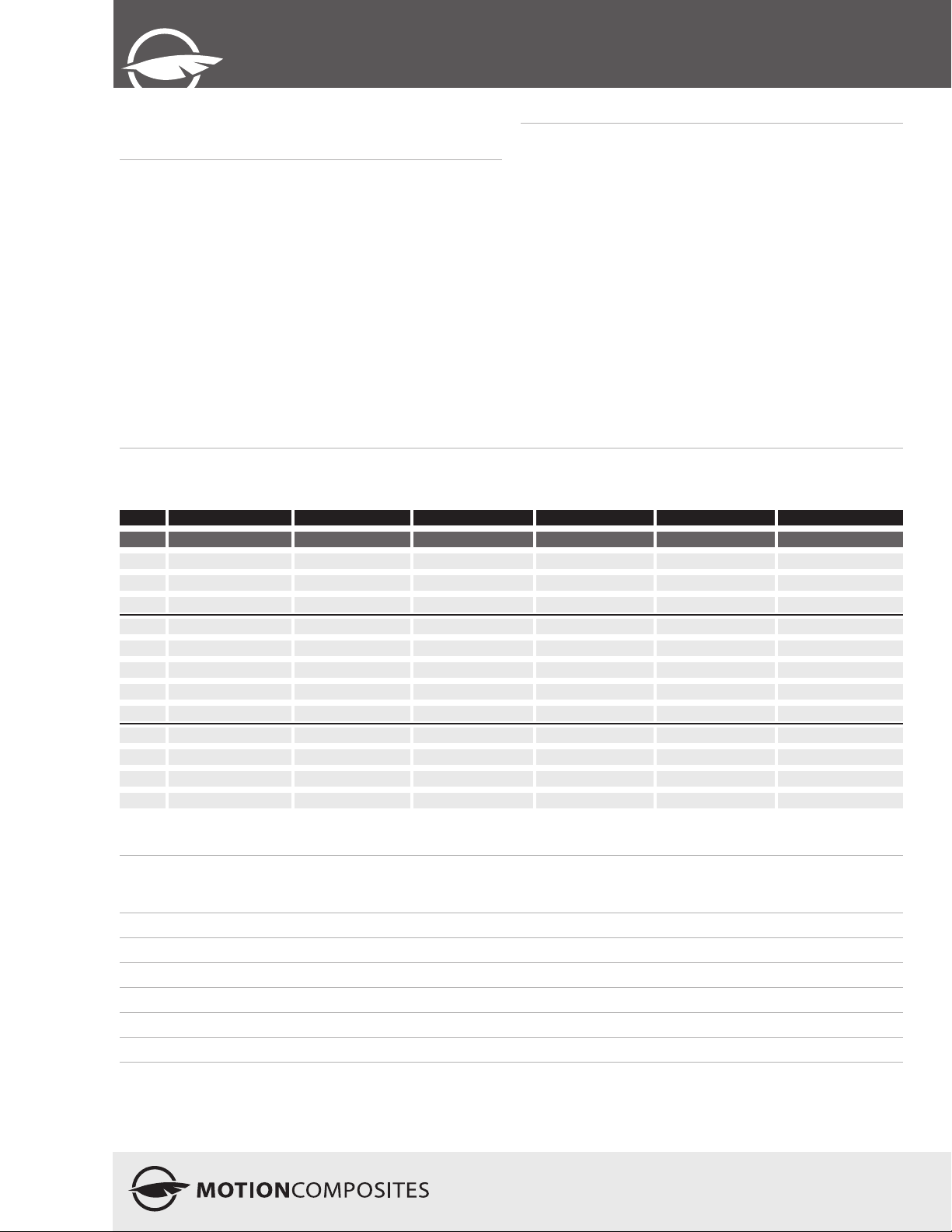
I.I TABLE “FRONT SEAT-TO-FLOOR HEIGHTS”
3” caster 4” caster 5” caster 6” caster 7” caster 8” caster
Stem bolt length Stem bolt length Stem bolt length Stem bolt length Stem bolt length Stem bolt length
Forks STD +1” +2” STD +1” +2” STD +1” +2” STD +1” +2” STD +1” +2” STD +1” +2”
4” P1 13 14 15 13 1/2” 14 1/2” 15 1/2”
P2 13 1/2” 14 1/2” 15 1/2” 14 15 16 14 1/2” 15 1/2” 16 1/2”
5” P1
P2 13 3/4” 14 3/4” 15 3/4” 14 3/4” 15 3/4” 16 3/4” 14 3/4” 15 3/4” 16 3/4”
P3 14 1/4” 15 1/4” 16 1/4” 14 3/4” 15 3/4” 16 3/4” 15 1/4” 16 1/4” 171/4” 15 3/4” 16 3/4” 17 3/4”
P4 14 3/4” 15 3/4” 16 3/4” 15 1/4” 16 1/4” 17 1/4” 15 3/4” 16 3/4” 17 3/4” 16 1/4” 17 1/4” 18 1/4” 16 3/4” 17 3/4” 18 3/4”
7” P1 16 1/4” 17 1/4” 18 1/4” 16 3/4” 17 3/4” 18 3/4”
P2 16 1/4” 17 1/4” 18 1/4” 16 3/4” 17 3/4” 18 3/4” 17 1/4” 18 1/4” 19 1/4”
P3 16 3/4” 17 3/4” 18 3/4” 17 1/4” 18 1/4” 19 1/4” 17 3/4” 18 3/4” 19 3/4” 18 1/4” 19 1/4” 20 1/4”
P4 16 3/4” 17 3/4” 18 3/4” 17 1/4” 18 1/4” 19 1/4” 17 3/4” 18 3/4” 19 3/4” 18 1/4” 19 1/4” 20 1/4” 18 3/4” 19 3/4” 20 3/4”
P5 16 3/4” 17 3/4” 18 3/4” 17 1/4” 18 1/4” 19 1/4” 173/4” 18 3/4” 19 3/4” 18 1/4” 19 1/4” 20 1/4” 18 3/4” 19 3/4” 20 3/4” 19 1/4” 20 1/4” 21 1/4”
I.II TABLE “REAR SEAT-TO-FLOOR HEIGHTS”
Wheel size Height available ± ¼”
20” wheel 12 ½” to 17”
22” wheel 13 ½” to 18”
24” wheel 14 ½” to 19”
25” wheel 15” to 19 ½”
26” wheel 15 ½” to 20”
23
Page 24

veloce
Motion Composites Inc.
519 J-Oswald Forest, suite 101
Saint-Roch-de-l’Achigan, Quebec
J0K 3H0 Canada
Phone: 1-866-650-6555
Fax: (450) 588-0200
[email protected]
www.motioncomposites.com
Conversion chart
Inches Metric Inches Metric Inches Metric Inches Metric
1/4” 0.63 mm 1” 2.54 cm 10” 25.40 cm 19” 48.26 cm
1/3” 0.84 mm 2” 5.08 cm 11” 27.94 cm 20” 50.80 cm
1/2” 1.26 mm 3” 7.62 cm 12” 30.48 cm 21” 53.34 cm
3/4” 1.90 mm 4” 10.16 cm 13” 33.02 cm 22” 55.88 cm
5” 12.70 cm 14” 35.56 cm 23” 58.42 cm
6” 15.24 cm 15” 38.10 cm 24” 60.96 cm
7” 17.78 cm 16” 40.64 cm 25” 63.50 cm
8” 20.32 cm 17” 43.18 cm 26” 66.04 cm
9” 22.86 cm 18” 45.72 cm
24
T (450) 588-6555 - 1 866 650-6555 F (450) 588-0200
 Loading...