

Page 1
user’s manual
Page 2

2
The lightning bolt flash with arrowhead
symbol, within an equilateral triangle,
is intended to alert the user to the presence of potentially “dangerous voltage” within the
product’s enclosure that may be sufficient to constitute a risk of electric shock.
In accordance with the European Union
WEEE (Waste Electrical and Electronic
Equipment) directive effective August 13,
2005, we would like to notify you that this product
may contain regulated materials which upon disposal, according to the WEEE directive, require special
reuse and recycling processing. For this reason Martin
Logan has arranged with our distributors in European
Union member nations to collect and recycle this product at no cost to you.
To find your local distributor please contact the
dealer from whom you purchased this product, email
info@martinlogan.com or visit the distributor locator at
www.martinlogan.com.
Please note, only this product itself falls under the
WEEE directive. When disposing of packaging and
other related shipping materials we encourage you to
recycle these items through the normal channels.
The exclamation point within an equilateral triangle is intended to alert the
user to the presence of important operating and maintenance (servicing) instructions in the
literature accompanying the appliance.
WARNING!
• Refer servicing to a qualified
technician.
• To prevent fire or shock hazard,
do not expose this module to moisture.
• Turn amplifier off should any abnormal
conditions occur.
• Do not drive speaker beyond its rated power.
Connection ............................ 4
Jumper Clips .......................4
Single Wire Connection ...............5
Bi-wire Connection ...................5
Passive Bi-amplification ................5
Active Bi-amplification .................6
Installation ............................. 7
Break In ..........................7
Installing On A Flat Surface .............7
Frequently Asked Questions ............... 7
Troubleshooting ........................ 8
Contacting Customer Service .............8
General Information ..................... 8
Warranty Information .................8
Serial Number ......................8
Service ..........................8
Specifications .......................... 9
Dimensional Drawings ................. 10
Serial Number:_____________________________
Record your serial number here for easy reference.
You will need this information when filling out your
warranty registration. The serial number is located
near the binding posts and on the product carton.
Page 3
3
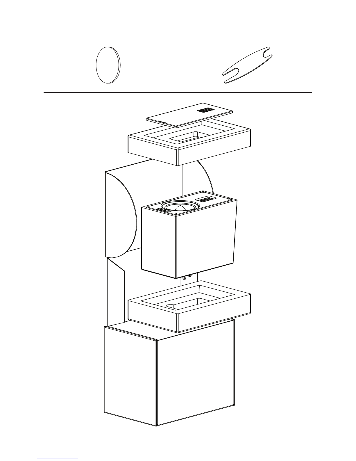
x2x4
Page 4

4
ConneCtion
WARNING! Turn your amplifier
off before making or breaking any
signal connections!
Use the best speaker cables you can. The length
and type of speaker cable used in your system will
have an audible effect. Under no circumstance
should a wire of gauge higher (thinner) than #16
be used. In general, the longer the length used,
the greater the necessity of a lower gauge, and
the lower the gauge, the better the sound, with
diminishing returns setting in around #8 to #12.
A variety of cables are available whose manufacturers claim better performance than standard heavy
gauge wire. We have verified this in many cases,
and the improvements available are often more
noticeable than the differences between wires of different gauge. The effects of cables may be masked
if equipment is not of the highest quality.
Connections are done at the signal input section
on the rear electronics panel of the speaker. Use
spade connectors for optimum contact and ease
of installation. Hand tighten the binding posts, but
do not overtighten—do not use a tool to tighten the
binding posts.
Be consistent when connecting the speaker cables
to the signal input terminals. Take care to assign
the same color cable lead to the (+) terminal on
both the left and right channel speakers. If bass is
nonexistent and you cannot discern a tight, coherent image, you may need to reverse the (+) and
(–) leads on one speaker to bring the system into
proper polarity.
JUMPER CLIPS
In some countries federal law prohibits
MartinLogan from supplying jumper clips. If none
are found installed under your speakers binding
posts, please refer to ‘Bi-Wire Connection’ for connection instructions.
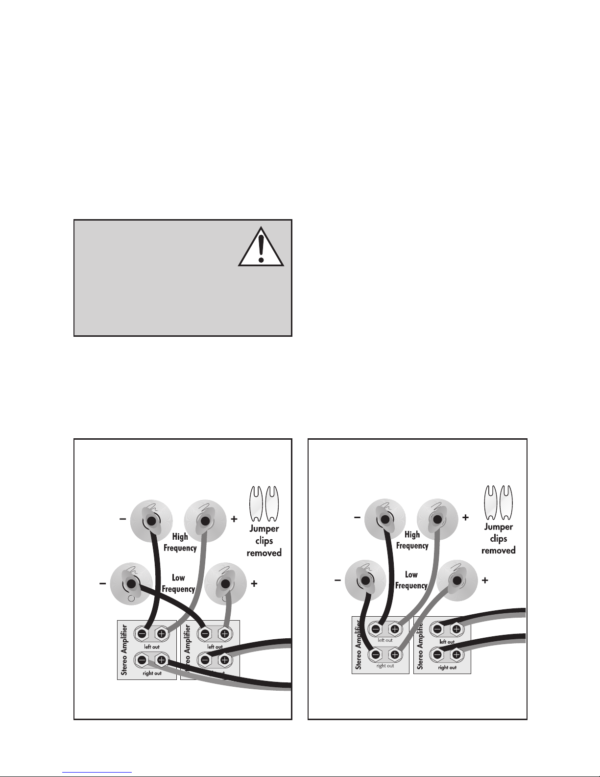
Fig. 1: Single-wire connection. One channel shown.
Fig. 2: Bi-wire connection. One channel shown.
Page 5
5
SINGLE WIRE CONNECTION
Please take note of the jumper clips installed
under the binding posts. These clips attach the
high-frequency and low-frequency sections of the
crossover together. Leaving these in place, connect the (+) wire from your amplifier to either red
(+)binding post and the (–) wire from your amplifier to either black (–) binding post (Fig. 1).
WARNING! Only after jumper
clips are removed may you connect
individual runs of speaker cable
from your amplifiers to the high-frequency and low-frequency signal input binding
posts. Damage will occur to your amplifiers if
the jumper clips are not removed.
BI-WIRE CONNECTION
This connection method replaces the jumper clips
installed under the binding posts with individual runs
of speaker wire from your amplifier. This doubles
the signal carrying conductors from the amplifier to
the speaker, thus direct-coupling each portion of the
crossover to the amplifier.
To bi-wire you must first loosen the binding posts
and remove the jumper clips. Connect one set of
wires to the upper set of binding posts which connect to the high-frequency drivers. Then connect
a second set of wires to the lower binding posts
which connect to the low-frequency drivers. Next,
connect both sets of wires to the appropriate terminals on your amplifier. Please take care to connect
both (+) wires to the (+) amplifier terminals and both
(–) wires to the (–) amplifier terminals. This is known
as a parallel connection (Fig. 2).
PASSIVE BI-AMPLIFICATION
For those that desire ultimate performance, these
speakers may be passively bi-amplified using the
existing internal passive crossover elements.
This method takes the bi-wiring concept one step
further. You will have a dedicated channel of
Fig. 3: Horizontal bi-amplification connection.
One channel shown.
Fig. 4: Vertical bi-amplification connection.
One channel shown.
Page 6

6
amplification directly connected to the high- and
low-frequency sections of the crossover. There are
two different methods for bi-amping with two stereo
amplifiers. The first and most common is referred
to as Horizontal Bi-amping. The second method is
referred to as Vertical Bi-amping. With either method you may use two stereo amplifiers or four mono
amplifiers, or two mono amplifiers and one stereo
amplifier. Get the idea? With either form of passive
bi-amplification, your preamplifier must have dual
outputs. If your preamplifier is not so equipped, you
must either purchase or construct a “Y” adapter.
Horizontal Passive Bi-Amplification
Horizontal bi-amping allows you to use two different types, models or brands of amplifiers (i.e. tubes
on top, transistor on the bottom). However, we
recommend that you use two identical amplifiers
(i.e. same brand and model). If you must use two
different amplifiers, it is essential that they have the
same gain or that one of the two have adjustable
gain so that you can match their gain characteristics. If the amplifiers of choice do not have the
same gain characteristics, then a sonic imbalance
will occur. With horizontal bi-amping, one amplifier drives the high-frequency section of the speaker
while the second amplifier drives the low-frequency
section. To horizontally bi-amp your speakers you
must loosen the binding posts and remove the
jumper clips. Connect the low-frequency amplifier
to the lower set of binding posts of both speakers.
Connect the high-frequency amplifier to the upper
set of binding posts. Next, connect the left and
right preamplifier outputs to the appropriate left
and right inputs of both amplifiers (Fig. 3).
Vertical Passive Bi-Amplification
The very nature of vertical bi-amping dictates that
both amplifiers be identical. With vertical bi-amping, each of the stereo amplifiers is dedicated to
one speaker. For instance, the left channel of each
amplifier drives the low-frequency section while the
right channel drives the high-frequency section. To
vertically bi-amp your speakers you must loosen the
binding posts and remove the jumper clips from
both speakers. Starting with one speaker, connect
the right channel to the lower binding posts and
the left channel to the upper binding posts. Repeat
the same procedure for the other speaker. Connect
the left preamplifier outputs to both inputs of the left
channel amplifier and the right preamplifier outputs
to both inputs of the right channel amplifier (Fig.
4).
ACTIVE BI-AMPLIFICATION
We do not recommend active bi-amplification.
The internal crossover can not be bypassed. This
connection method seriously degrades performance.
Page 7

7
BREAK IN
Allow approximately 72 hours of break-in at 90
dB (moderate levels) before any critical listening.
INSTALLING ON A FLAT SURFACE
If you have a surface that provides a wide, level,
and stable platform, the speaker can be placed
directly on top. When using the speaker in this
configuration, affix the pads to the bottom of the
speaker at the rear contact points (fig. 5). Note:
This speaker is not magnetically shielded and
therefore should not be placed directly beside or
atop a CRT television.
Toe-In: When installed on a surface and used as
front channels we recommend aiming your speakers towards the primary listening position.
installation
WARNING! Installation other
than that described in the body of
this document requires specific
documentation from MartinLogan.
Fig. 5
How do I clean my speakers?
Use a dust free cloth (such as a micro fiber cloth)
or a soft brush to remove dust from your speakers.
Do not spray any kind of cleaning agent on or in
close proximity to the drivers.
Could you suggest a list of suitable electronics and cables ideal for MartinLogan
speakers?
We have no favorites and use electronics and
cables quite interchangeably. We would suggest
listening to a number of brands—and above all
else—trust your ears. Dealers are always the best
source for information when purchasing additional
audio equipment.
Is there likely to be any interaction
between my speakers and the television in my A/V system?
Yes. These speakers are not shielded and should
be kept at least 2 feet away from a CRT television.
Will exposure to sunlight affect the life
or performance of my speakers?
We recommend against placing any loudspeaker
in direct sunlight. Ultraviolet (UV) rays from the sun
can cause deterioration of cabinet, speaker cones,
etc. Small exposures to UV will not cause a problem. Filtering of UV rays through glass will greatly
reduce the negative effects.
Frequently asked questions
Page 8

8
WARRANTY INFORMATION
Your speakers are provided with an automatic
Limited 90 Day Warranty coverage. You have
the option, at no additional charge, to receive a
Limited 5 Year Warranty coverage. To obtain the
Limited 5 Year Warranty coverage you need to
complete and return the Certificate of Registration
to MartinLogan within 30 days of purchase. For
your convenience MartinLogan also offers online
warranty registration at www.martinlogan.com.
MartinLogan may not honor warranty service
claims unless we have a completed Warranty
Registration card on file! If you did not receive a
Certificate of Registration with your new speakers
you cannot be assured of having received new
units. If this is the case, please contact your authorized MartinLogan dealer.
SERIAL NUMBER
Serial number is located on back of the speaker,
directly beneath the binding posts. The serial number may also be found on the product carton.
SERVICE
Should you use your MartinLogan product in a
country other than the one in which it was originally
purchased, we ask that you note the following:
1 The appointed MartinLogan distributor for any
given country is responsible for warranty servicing
only on units distributed by or through it in that country in accordance with its applicable warranty.
2 Should a MartinLogan product require servicing in a country other than the one in which
it was originally purchased, the end user may
seek to have repairs performed by the nearest
MartinLogan distributor, subject to that distributor’s local servicing policies, but all cost of repairs
(parts, labor, transportation) must be borne by the
owner of the MartinLogan product.
3 If, after owning your speaker for six months, you
relocate to a country other than the one in which
you purchased your speaker, your warranty may be
transferable. Contact MartinLogan for details.
General inFormation
MartinLogan customer service is available
Monday–Friday between the hours of 8am–5pm
(central time) by calling (785) 749-0133 or by
emailing service@martinlogan.com.
ContaCtinG Customer serviCe
No Output
• Check that all system components are turned
on and source material is playing.
• Check speaker wires and connections.
• Check all interconnecting cables.
• If you are unable to resolve your problem,
please contact your dealer or MartinLogan customer service (see below).
troubleshootinG
Page 9

9
speCiFiCations*
Frequency Response .....................
Dispersion ............................
Sensitivity.............................
Impedance ............................
Crossover Frequency.....................
High Frequency Driver ...................
Low Frequency Drivers ...................
Cabinet ..............................
Components ...........................
Recommended Amplifier Power.............
Binding Post Inputs ......................
Weight...............................
Dimensions (HxWxD) ....................
50–25,000 Hz ± 3 dB
80° x 30°
92 dB @ 2.83 volts/ meter
4 Ohms. Compatible with 4, 6 or 8 Ohm rated
amplifiers.
2,200 Hz
1.2” x 2.4” (3.2cm x 6.1cm) Folded Motion
Transducer with 4.5” x 2.75” (11.4cm x 7cm)
diaphragm.
6.5” (16.5cm) aluminum cone with cast polymer
basket.
Non-resonant asymmetrical chamber
format. Rigid structured dust cap to reduce cone
break-up modes.
Ported
Custom air core coil and low DCR steel laminate
inductors. Polypropylene film capacitors in series
and low DF electrolytic capacitors in parallel.
Tweeter thermal/current protection.
20–250 watts
Custom 5-way tool-less binding posts
18.5 lbs. (8.4 kg)
13.5” x 7.6” x 11.8”
(34.3cm x 19.2cm x 30cm)
*Specifications are subject to change without notice.
Page 10

Lawrence, Kansas, USA tel 785.749.0133 fax 785.749.5320 www.martinlogan.com
Rev. #032514©2014 MartinLogan Ltd. All rights reserved.
®
dimensional drawinGs
Page 11

guide de l’utilisateur
Page 12

12
Le symbole de l’éclair avec une pointe en
forme de flèche, dans un triangle équi-
latéral, avertit l’utilisateur de la présence
d’une « tension dangereuse » potentielle près du produit
qui peut être suffisante pour constituer un risque de
décharge électrique.
En vertu de la directive WEEE de l’Union européenne (directive sur les déchets électriques
et électroniques) entrée en vigueur le 13 août
2005, nous vous avisons que ce produit pourrait contenir des matériaux réglementés dont l’élimination doit faire
l’objet de procédures de réutilisation et de recyclage
particulières. À cette fin, MartinLogan a demandé à ses
distributeurs dans les pays membres de l’Union européenne de reprendre et de recycler ce produit gratuitement.
Pour trouver le distributeur le plus près, communiquez avec
le revendeur du produit, envoyez un courriel à info@martinlogan.com ou consultez le site Web martinlogan.com.
Notez que seul le produit est régi par la directive
WEEE. Nous vous encourageons à recycler les matériaux d’emballage et autres matériaux d’expédition
selon les procédures normales.
Le point d’exclamation dans un triangle équilatéral avertit l’utilisateur de la
présence de directives importantes en
matière de fonctionnement et d’entretien (service)
dans les documents qui accompagnent l’appareil.
AVERTISSEMENT!
• Pour les réparations, faites appel à
un technicien compétent.
• Pour éviter les risques d’incendie
ou de décharge électrique, n’exposez pas ce
module aux vapeurs d’eau ni à l’humidité.
• Veuillez éteindre l’amplificateur en cas de
conditions anormales.
• Ne poussez pas l’enceinte au-delà de sa puis-
sance nominale.
Raccordement .......................14
Pinces de Démarrage ................14
Raccord à Un Fil ...................15
Raccord à Deux Fils .................15
Bi-Amplification Passive ...............15
Bi-Amplification Active ................16
Installation .........................17
Rodage .........................17
Installation Sur Une Surface Plane ........17
Foire Aux Questions ..................17
Dépannage .........................18
Communiquer Avec Le Service à La Clientèle . 18
Renseignements Généraux .............. 18
Renseignements Sur La Garantie .........18
Numéro de Série ...................18
Service .........................18
Spécifications .......................19
Plans Dimensionnels ..................20
Numéro de Série :__________________________
Veuillez inscrire votre numéro de série ici pour pouvoir vous y référer facilement. Vous aurez besoin
de ce renseignement lorsque vous remplirez votre
enregistrement à la garantie. Le numéro de série
est situé près des bornes de raccordement et sur
l’emballage du produit.
Page 13

13
x2x4
Page 14

14
Utilisez les meilleurs câbles d’enceinte possible.
La longueur et le type de câble d’enceinte utilisés
avec votre système auront un effet audible. Vous
ne devez pas utiliser un câble de calibre supérieur
(plus mince) au no 16, en aucun cas. En général,
plus le câble est long, plus il doit être de calibre
inférieur, et plus le calibre est bas, meilleur est le
son; le paramètre de diminution des retours doit
être établi du no 8 au no 12.
De nombreux câbles différents sont disponibles
auprès de fabricants qui affirment que leur rendement est meilleur que celui du câble à calibre
élevé courant. Nous avons vérifié cette affirmation dans de nombreux cas, et les améliorations
disponibles sont souvent plus notables que les
différences entre les câbles de calibre différent.
Les effets des câbles peuvent être masqués si
l’équipement n’est pas de la plus haute qualité.
Les raccords sont effectués à la section du signal
d’entrée située sur le panneau électronique arrière
de l’enceinte Theos. Utilisez des cosses rectangulaires pour un contact optimal et pour faciliter
l’installation. Serrez les bornes de raccordement
à la main, sans trop serrer – n’utilisez pas d’outil
pour serrer les bornes de raccordement.
Faites preuve de cohérence en branchant les
câbles de l’enceinte aux bornes du signal d’entrée.
Assurez-vous d’attribuer la même couleur à la
borne (+) des canaux de gauche et de droite. Si
aucune grave n’est présente et que vous ne discernez pas une image serrée et cohérente, vous
pourriez devoir inverser les câbles (+) et (-) d’un
côté pour que le système ait la bonne polarité.
PINCES DE DÉMARRAGE
Dans certains pays, la loi fédérale interdit à
MartinLogan de fournir des pinces de démarrage.
Si aucune pince de démarrage n’est installée
sur les bornes de raccordement des enceintes,
consultez la section « Raccord à deux fils » pour
obtenir les instructions relatives au raccordement.
raCCordement
AVERTISSEMENT! Éteignez
l’amplificateur avant de faire des
raccordements ou d’interrompre
tout raccordement de signal!
Fig. 1:
Raccord à un fil. Un canal illustré.
Fig. 2:
Raccord à deux fils. Un canal illustré.
Page 15

15
RACCORD À UN FIL
Veuillez vérifier si des pinces de démarrage sont
installées sous les bornes de raccordement. Ces
pinces permettent de joindre les sections de haute
et de basse fréquence du répartiteur (crossover).
En les laissant en place, branchez le câble (+) de
votre amplificateur à la borne de raccordement
rouge et le câble (-) de votre amplificateur à la
borne de raccordement noire (voir figure 1).
MISE EN GARDE! Seulement
après avoir enlevé les pinces de
démarrage, vous pouvez brancher
les tracés de câble d’enceinte individuels de
votre amplificateur aux bornes de raccordement du signal d’entrée de haute et de basse
fréquence. Des dommages seront causés à vos
amplificateurs si les pinces de démarrage ne
sont pas enlevées.
RACCORD À DEUX FILS
Cette méthode de raccordement remplace les
pinces de démarrage (Jumper Clips) installées sous
les bornes de raccordement avec des tracés de
câble d’enceinte individuels à partir de votre amplificateur. Cette mesure permet de doubler le signal
qui achemine les conducteurs de l’amplificateur à
l’enceinte, permettant ainsi de coupler directement
chaque partie du répartiteur vers l’amplificateur.
Pour effectuer un raccord à deux fils, vous devez
d’abord desserrer les bornes de raccordement
et enlever les pinces de démarrage. Branchez un
ensemble de câbles à l’ensemble de bornes de raccordement de la partie supérieure qui permettent un
branchement aux haut-parleurs de haute fréquence.
Branchez ensuite un deuxième ensemble de câbles
aux bornes de raccordement de la partie inférieure
qui permettent un branchement aux haut-parleurs
de basse fréquence. Ensuite, branchez les deux
ensembles de câbles aux bornes appropriées de
votre amplificateur. Prenez soin de brancher les
deux câbles (+) aux bornes (+) de l’amplificateur et
les deux câbles (–) aux bornes (–) de l’amplificateur.
C’est ce qu’on appelle un raccord parallèle (voir la
figure 2).
BI-AMPLIFICATION PASSIVE
Pour obtenir le meilleur rendement qui soit, ces
enceintes peuvent être bi-amplifiées passivement à
l’aide des éléments de répartiteur passifs internes
existants.
Fig. 3: Raccordement par bi-amplification horizontale. Un canal illustré.
Fig. 4: Raccordement par bi-amplification verticale. Un canal illustré.
Page 16

16
Cette méthode pousse le concept du raccordement à deux fils une étape plus loin. Vous aurez un
canal d’amplification dédié branché directement
aux sections de basse et de haute fréquence du
répartiteur. Il existe deux méthodes différentes de
bi-amplification avec deux amplificateurs stéréo.
La première et la plus courante est appelée biamplification horizontale. La deuxième méthode est
appelée bi-amplification verticale. Avec ces deux
méthodes, vous pouvez utiliser deux amplificateurs
stéréo ou quatre amplificateurs mono, ou encore
deux amplificateurs mono et un amplificateur stéréo.
Vous voyez le portrait? Avec une forme ou l’autre
de bi-amplification, votre préamplificateur doit posséder des sorties double. Si votre préamplificateur
n’est pas équipé de la sorte, vous pouvez acheter
ou construire un adaptateur en Y.
Bi-amplification passive horizontale
La bi-amplification horizontale vous permet
d’utiliser deux modèles, marques ou types différents d’amplificateur (c.-à-d. : tubes sur le dessus,
transistor sur le dessous). Toutefois, nous vous
recommandons d’utiliser deux amplificateurs identiques (c.-à-d. même marque et même modèle). Si
vous devez utiliser deux amplificateurs différents,
il est essentiel qu’ils aient le même gain ou que
l’un des deux amplificateurs soit doté d’un gain
réglable afin que vous puissiez agencer leurs caractéristiques de gain. Si les amplificateurs choisis
n’ont pas les mêmes caractéristiques de gain, un
déséquilibre sonore surviendra.
Dans le cas de la bi-amplification horizontale, un
amplificateur traite la section de haute fréquence
de l’enceinte et l’autre traite la section de basse
fréquence. Pour bi-amplifier horizontalement vos
enceintes, vous devez desserrer les bornes de rac-
cordement et enlever les pinces de démarrage.
Branchez l’amplificateur de basse fréquence à
l’ensemble de bornes de raccordement le plus bas
des deux enceintes. Branchez l’amplificateur de
haute fréquence à l’ensemble de bornes de raccordement le plus haut. Ensuite, branchez les sorties
de gauche et de droite du préamplificateur aux
entrées de gauche et de droite appropriées des
deux amplificateurs (voir figure 3).
Bi-amplification passive verticale
La nature de la bi-amplification verticale dicte que
les deux amplificateurs sont identiques. Dans le cas
de la bi-amplification verticale, chaque amplificateur stéréo est dédié à une enceinte. Par exemple,
le canal de gauche de chaque amplificateur traite
la section de basse fréquence, tandis que le canal
de droite traite la section de haute fréquence.
Pour bi-amplifier verticalement vos enceintes,
vous devez desserrer les bornes de raccordement
et enlever les pinces de démarrage des deux
enceintes. En commençant avec une enceinte,
branchez le canal de droite aux bornes de raccordement inférieures et le canal de gauche aux
bornes de raccordement supérieures. Répétez la
même procédure pour l’autre enceinte. Branchez
les sorties du préamplificateur de gauche aux deux
entrées de l’amplificateur du canal de gauche et
les sorties du préamplificateur de droite aux deux
entrées du préamplificateur du canal de droite (voir
figure 4).
BI-AMPLIFICATION ACTIVE
Nous ne recommandons pas la bi-amplification
active. La fonction de répartiteur interne ne peut
pas être contournée. Cette méthode de raccordement dégrade grandement le rendement.
Page 17

17
RODAGE
Un rodage d’environ 72 heures à 90 dB (niveaux
d’écoute moyens) est nécessaire avant écoute critique.
INSTALLATION SUR UNE SURFACE PLANE
Si vous disposez d’une plateforme large, au niveau
et stable, vous pouvez placer l’enceinte directement
dessus. Lorsque vous utilisez l’enceinte dans cette
configuration, fixez les coussinets en caoutchouc
sur la partie inférieure de l’enceinte sur les points de
contact arrière (fig. 5). Remarque : cette enceinte
n’est pas dotée d’une protection magnétique; par
conséquent, vous ne devez pas la placer directement à côté ou au-dessus d’une télévision dotée
d’un écran à tube cathodique (CRT).
installation
AVERTISSEMENT! Une installation autre que celle décrite dans le
présent document exige des documents particuliers de MartinLogan.
Comment nettoyer les enceintes?
Utilisez un linge exempt de poussière (comme un
linge en microfibres) ou une brosse à poils doux
pour enlever la poussière sur les enceintes. Ne
vaporisez pas de produits nettoyants sur les
haut-parleurs ou à proximité de ceux-ci.
Pouvez-vous me proposer une liste
d’appareils électroniques et de
câbles qui conviennent aux enceintes
MartinLogan?
Nous n’avons aucun produit préféré et nous utilisons les appareils électroniques et les câbles de
façon assez interchangeable. Nous vous proposons
d’écouter plusieurs marques et surtout, de faire confiance à votre ouïe. Les revendeurs sont toujours la
meilleure source de renseignements lorsque vous
achetez de l’équipement audio supplémentaire.
Peut-il y avoir une interaction entre mes
enceintes et la télévision dans mon système A/V?
Oui. Ces enceintes ne sont pas protégées et doivent
être placées à au moins deux pieds d’une télévision
dotée d’un écran à tube cathodique (CRT).
Est-ce que l’exposition à la lumière
solaire nuira au rendement ou à la
durée de vie de mes enceintes?
Nous recommandons de ne pas exposer les
enceintes directement à la lumière solaire. Les rayons ultraviolets (UV) du soleil peuvent entraîner la
détérioration du boîtier, des cônes de l’enceinte,
etc. Les expositions de courte durée aux rayons UV
ne posent pas de problème. La filtration des rayons UV par le verre diminuera grandement leurs
effets négatifs.
Foire aux questions
Fig. 5
Page 18

18
RENSEIGNEMENTS SUR LA GARANTIE
Vos enceintes sont vendues avec une garantie limitée
automatique de 90 jours. Vous avez la possibilité
d’obtenir, sans frais supplémentaires, une garantie limitée de cinq ans. Pour obtenir la garantie limitée de
cinq ans, vous devez remplir et retourner le certificat
d’enregistrement à MartinLogan dans les 30 jours
qui suivent la date d’achat. Pour plus de commodité,
MartinLogan permet également l’enregistrement en
ligne à la garantie à l’adresse www.martinlogan.com.
MartinLogan pourrait ne pas honorer les réclamations
de service au titre de la garantie à moins d’avoir
une carte d’enregistrement à la garantie dûment
remplie dans ses dossiers! Si vous n’avez pas reçu
de certificat d’enregistrement à la garantie avec vos
nouvelles enceintes, il vous est impossible de savoir si
vous avez reçu des enceintes neuves. Le cas échéant,
communiquez avec votre revendeur MartinLogan.
NUMÉRO DE SÉRIE
Un numéro de série est situé derrière l’enceinte,
directement sous les bornes de raccordement. Le
numéro de série est également inscrit sur l’emballage
du produit.
SERVICE
Si vous utilisez votre produit MartinLogan dans un pays
autre que celui où il a été acheté à l’origine, nous vous
demandons de noter ce qui suit :
1 Le distributeur MartinLogan désigné pour tout pays
donné est responsable du service au titre de la garantie uniquement pour les appareils distribués par ce
pays ou par l’entremise de celui-ci conformément à sa
garantie applicable.
2 Si un produit MartinLogan doit faire l’objet de
réparations (service) dans un pays autre que celui où
il a été acheté à l’origine, l’utilisateur final peut faire
réparer le produit chez le distributeur MartinLogan le
plus proche, sous réserve des politiques de service
locales de ce distributeur, mais tous les coûts des
réparations (pièces, main-d’œuvre et transport) seront
assumés par le propriétaire du produit MartinLogan.
3 Si, après avoir possédé l’enceinte pendant six
mois, vous déménagez dans un pays autre que celui
où vous avez acheté l’enceinte, votre garantie peut
être transférable. Communiquez avec MartinLogan
pour obtenir tous les détails.
renseiGnements Généraux
Le service à la clientèle de MartinLogan est disponible du lundi au vendredi, de 8 h à 17 h
(heure normale du Centre) en composant le (785)
749-0133 ou en envoyant un courriel à l’adresse
service@martinlogan.com.
Communiquer aveC le serviCe à la Clientèle
Aucun signal de sortie
• Vérifiez que toutes les composantes du système
sont allumées et que le matériel source est lu.
• Vérifiez les câbles de l’enceinte et les raccords.
• Vérifiez tous les câbles interconnectés.
• Si vous n’est pas capable de résoudre votre
problème, veuillez communiquer avec votre
revendeur ou le service à la clientèle de
MartinLogan (voir ci-dessous).
dépannaGe
Page 19

19
spéCiFiCations*
Réponse de Fréquence ...................
Dispersion ............................
Sensibilité.............................
Impédance ............................
Fréquence de Raccord....................
Haut-parleur Paute Fréquence..............
Haut-parleur Basse Fréquence..............
Boîtier ...............................
Composantes ..........................
Puissance d’Amp Recommandée ...........
Bornes de Raccordement..................
Poids ................................
Dimensions (HxLxP) .....................
50–25 000 Hz ± 3 dB
80° x 30°
92 dB à 2,83 volts/mètre
4 Ohms. Compatible avec des amplificateurs classés 4, 6, ou 8 Ohms.
2 200 Hz
1,25po x 2,4po (3,2cm x 6,1cm) Transducteur
motion plié avec diaphragme de 4,5po x 2,75po
(11,4cm x 7cm).
Cône en aluminium de 6,5 po (16,5 cm) avec
panier en polymère moulé. Format de chambre
asymétrique non résonant. Capuchon contre la
poussière rigide pour diminuer les modes de bris
de cône.
Porté
Bobine centrale à air sur mesure et inducteurs DCR
en acier laminé bas. Condensateurs à pellicule
polypropylène
en série et condensateurs DF électrolytiques bas en parallèle. Protection thermique/courant
générale du système.
20–250 watts
Bornes de raccordement sur mesure
18,5 lb (8,4 kg)
13,5 po x 7,6 po x 11,8 po
(34,3 cm x 19,2 cm x 30 cm)
*Les spécifications peuvent changer sans préavis.
Page 20

Lawrence, Kansas, USA tél. 785.749.0133 téléc. 785.749.5320 www.martinlogan.com
Rev. #032514©2014 MartinLogan Ltd. Tous droits réservés.
®
plans dimensionnels
 Loading...