

Page 1

Instruction Manual
PM Series
Copyright © 02/02
Motic Microscopes, European Division
Page 2
PM-2805
-2-
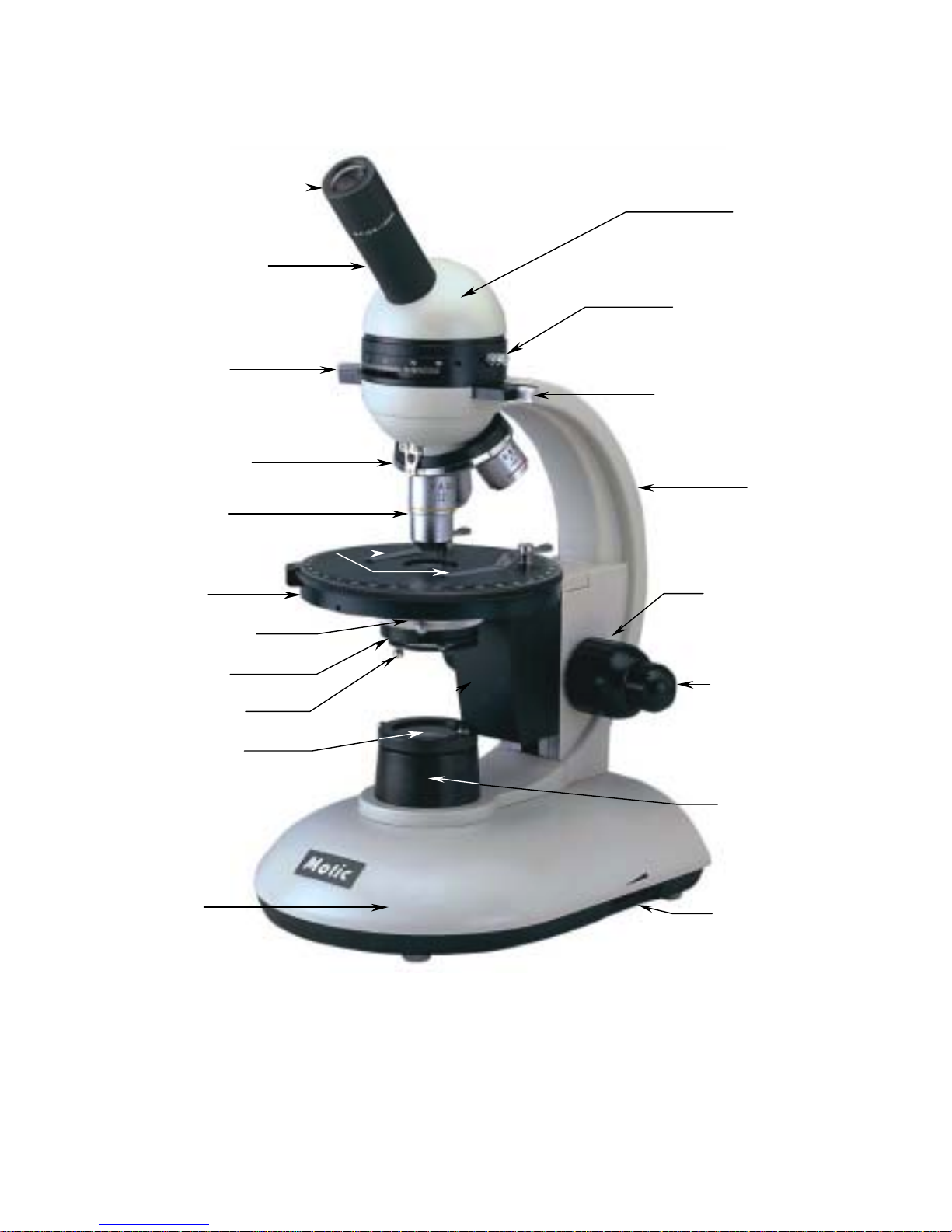
1. Eyepiece
3. Analyzer
4. Revolving
nosepiece
5.Objectives
6. Stage clips
7. Stage
8. Condenser
9. Diaphragm
10. Filter holder
14. Bertrand Lens
13. Head
16. Arm
2. Eyepiece tube
17. Coarse focus
18. Fine focus
19. Illuminator
20. Light
intensity control
12. Base
15. Plates λ and 1/4
λ
11. Polarizer
Page 3

Introduction
Thank you for your purchase of a Motic microscope. Motic microscopes are precision instruments, subjected
to meticulous examination in order to reach you in perfect condition. Their design combines easy
management and optimum functioning with minimum maintenance.
The information contained in this manual is likely to go beyond what the average user needs to know to use
the microscope, however, it is provided to answer any queries that may arise.
Your new microscope combines high performance features, with an excellent degree of optical resolution
and clarity of image It incorporates a circular rotating stage with a 1º graduation, that permits the exact
positioning of the sample. Objectives located on a ball bearing nosepiece allowing movement in both
directions, a precision coarse and fine focusing system; a moveable Abbe condenser with a numerical
aperture of 1.25 N.A. and a built-in 12V/ 20W halogen variable light source.
These instructions should be read carefully before operating the microscope. They will permit you to use
your new microscope to its fullest capabilities. Terminology used to describe components and controls can
be found in the diagram on page 2.
These instructions are based on the assembly and use of the PM-2805 model with additional notes
applying specifically to the PM-1805 model.
Unpacking
All components of the microscope have been carefully packed to make sure they reach you in perfect
condition. We recommend that you do not discard any packing containers in case you need to return the
microscope or store it for long periods of time; or should it become necessary to transport it to a technical
service for any repair, or maintenance procedure.
The box should contain the following components, depending on the model:
• PM-1805: A microscope mounted with a monocular head, eyepiece, circular stage, 1,25 A.N.
condenser, three objectives, a polarizer integrated into the illuminator and an analyser. Also included
is a blue filter, a protective cover and two 2mm and 0.85mm hexagonal keys.
• PM-2805: A microscope with a monocular head with an analyser, a Bertrand lens and some
integrated plates λ and 1/4 λ, eyepiece, circular stage, 1,25 A.N. condenser, three objectives, a
polarizer integrated into the illuminator. Also included is a blue filter, a protective cover and two
2mm and 0.85mm hexagonal keys.
Remove and handle the microscope and all its components with extreme care.
Avoid touching the lenses of the optical elements and keep clear of contact with dust, water or other
contaminating agents, as they could stain, or damage the lens surface and affect the quality of the
image.
A. Place the microscope in a vertical position on a flat, clean and stable surface.
B. Extract the rest of the components from the box.
-3-
Page 4

Description of components
1. Head (13). Monocular and 360º rotating so that another user can observe without the necessity of
moving the microscope.
2. Eyepiece (1). The group of lenses closest to the eye, they magnify the image formed by the
objectives. In monocular models, the eyepiece contains a pointer to signal any particular aspect of a
sample to another user.
3. Revolving nosepiece (4). Magnification can be changed by rotating the nosepiece. An indicator in the
optical path indicates the correct positioning of the objective.
4. Objectives (5). The group of lenses closest to the sample or microscopic slide. They form the first
image.
5. Stage (7). Surface where the slide is placed. The stage is circular and can be turned 360º , stage
clips are also provided.
6. Condenser (8). Optimises the illumination to obtain a high level of resolution and image contrast.
7. Focus knobs (17-18). Situated on both sides of the microscope arm, the bigger, coarse focus knob,
permits a first approximate focus, and the smaller, fine focus knob, permits a precise adjustment of
focus.
In the model PM-1805 The knobs are separate, and on the model PM-2805 they are coaxial.
8. Illumination (19-20). These models include 12V and 20W Halogen bulb, pre-centred and can be
regulated in intensity.
Assembly
All the steps described for the assembly of the microscope must be undertaken with extreme care ,
and without forcing the placement of the distinct parts and elements of the microscope.
A. Filter: This filter should be used if the illumination on the field of vision appears yellowed.
Place the blue filter in the filter holder (11) situated under the condenser (10), open the filter holder
by pulling out horizontally. Make sure that the filter is placed correctly, and close the filter holder.
B. Analyser: Only for the PM-1805. Connect the analyser to the eyepiece (1). In the PM-2805 the
analyser is already installed in the head.
Warning: Before connecting the microscope to a power source, ensure that the voltage coincides with that of
the microscope.
-4-
Page 5

Operation
A. Starting up.
1. Before using the microscope, adjust the intensity of
the light (20) to its minimum. This must be done
each time the microscope is turned on or off to
prolong the life of the bulb.
2. Press the power switch, to ON position. (Fig. 1)
3. Turn light intensity control until the image is lit up.
4. Light intensity should be adjusted according to the
objective used or the type of preparation observed.
B. Focussing the microscope.
1. Turn the revolving nosepiece (4) and place the 4X
objective (5) in the optical path, making sure that it has been correctly clicked securely into
place.
2. Turn the coarse focus knob (17) until the stage (7) is as low down as possible.
3. Place the microscopic slide on the stage, making sure that the cover slip is facing upwards.
4. Raise the stage clips by pressing down on the back end, place slide under clips, releasing
pressure so the slide is secured into place.
5. Ensure that the sample on the slide is in the optical eye.
6. Looking through the eyepiece (1), turn the coarse focus knob until the slide appears in focus.
7. Readjust the focus with the fine focus knob (18) until the image appears completely sharp.
C. Adjusting the aperture of the diaphragm.
The diaphragm aperture (9) should not be used as a light intensity control. Its function is to
obtain the best possible resolution of the sample in proportion with high image contrast. The
smaller the aperture, the better the image contrast, although if closed, too much resolution
will not be correct. The best approach is to experiment. Suggested apertures are as follows:
OBJECTIVE IRIS APERTURE
4X Totally closed to 1/8 open.
10X From 1/8 to 1/4
40X From 1/4 to 1/2
100X From 1/2 to 3/4
-5-
On switch
Fuse
Fig. 1
Page 6

D. Changing the magnification.
1. Position the 10X objective (5) in the optical path.
2. This microscope has already been parfocalised, although it is possible that there are small
differences between the objectives. In this case, the focus should be readjusted with the fine
focus knob (18).
3. When changing between objectives 40X y 100X (optional) do so with great care, ensuring
that the objectives do not rub against the slide and damage the lens front.
4. To obtain maximum resolution with the 100X objective (optional), it is necessary to apply
immersion oil between the cover slip and the front lens of the objective.
a. Only use a tiny amount of immersion oil, a drop should be enough.
b. If air bubbles appear, they can be eliminated by rotating the nosepiece slightly,
and then repositioning it.
c. After observing, all parts that have come into contact with immersion oil must be
cleaned. Use a soft cotton cloth, lightly dampened with Xylene. If the 100X
objective is not cleaned, the oil will dry on the lens front, and block the view. This
could also damage the lens.
NB: Immersion oil must ONLY be used with the 100X objective. If it comes into
contact with any other objective, it must be cleaned immediately.
E. Critical illumination on bright field.
It is the optimum degree of illumination that perfectly proportions the group of elements used for
illumination, basically the condenser. To achieve critical illumination, an object on the illuminator
must be brought into focus.
1. Move the polarizer (11) from the illumination field.
2. In the case of the PM-1805, remove the analyser.
3. Focus on a slide with the 10X objective (5).
4. Place a flat object on the illuminator (19). The object must be one that allows light to pass
through, for example, a slide.
5. Without letting go of the slide, bring it into focus, moving the condenser (8) by turning the
collar with the other hand.
6. When critical illumination has been achieved, the slide can be removed from the illuminator.
If anything irregular appears in the field of view, an optical element of the illuminator appears
in focus for example, move the condenser slightly so it is out of focus. This should give you
the best illumination possible, and that closest to critical illumination.
-6-
Page 7

F. Polarized illumination.
Light moves by vibrating on an infinite number of plains. The purpose of the polarizer is to provide
the light so that it moves in a single direction, on parallel plains. A secondary polarizer, known as the
analyser is situated above the objectives, “ crossing” the primary polarizer: that is to say, placed at a
90º angle to the emitted light of the primary polarizer, and so “ blocking” the light’ s path: what is called
the position of light extinction. Through the eyepiece the field of view then appears dark. Observation
through a polarizing microscope is called orthoscopic observation. Polarized light is mainly used for
the observation of mineral samples, although it can also be used to observe textiles, plastics, paper
and some biological specimens.
1. The polarizer (11) must be placed over the illumination field (19).
2. Without any slide placed on the stage, place the analizer (3) into 90º position. For the PM-1805
place the analizer onto the eyepiece and turn it until the field of view becomes dark.
For different observing techniques with polarising light,
Maintenance
WARNING: FOR YOUR SECURITY, SWITCH OFF AND REMOVE PLUG FROM POWER SOURCE
OUTLET BEFORE MAINTAINING YOUR MICROSCOPE, TO AVOID SHOCK OR FIRE HAZARD.
CONSULT YOUR DISTRIBUTOR IF YOUR MICROSCOPE REQUIRES ANY MAINTENANCE OR
REPARATION PROCEDURE NOT COVERED IN THIS INSTRUCTION MANUAL.
A. Optical Maintenance
1. Do not attempt to remove any optical component.
2. Before cleaning any lens, remove surface traces of dust using a fine brush, especially for lenses,
or with low pressure . Both can be obtained in any photography shop.
3. Cleaning the eyepiece
a. Do not remove the eyepiece (1) from the eyepiece tube. (2).
b. Only clean the lens surface, misting the lens with breath.
c. Afterwards, dry the lens with special lens paper in circular movements, from center out
to the exterior of the lens. Do not wipe the lenses when dry, as they can be easily
scratched.
4. Cleaning the objectives.
a. Do not remove the objectives (5) from the microscope.
b. Only clean the surface area. Use a soft cotton cloth dampened with Xylene. Dry the lens
using the same cloth.
5. Cleaning the condenser. (8)
a. Only clean the top lens surface of the condenser using any of the methods mentioned
above for cleaning the eyepieces or objectives.
-7-
Page 8

6. Cleaning the illuminator lens. (19)
a. Only clean the top lens of the illuminator using any of the methods mentioned above for
cleaning the eyepieces or objectives.
B. Electrical maintenance
WARNING: FOR YOUR SECURITY, SWITCH OFF AND REMOVE PLUG FROM POWER
SOURCE OUTLET BEFORE MAINTAINING YOUR MICROSCOPE, TO AVOID SHOCK OR FIRE
HAZARD.
1. Changing the bulb.
a. Place the microscope on its side with extreme
care, especially with the eyepiece (1).
b. Completely unscrew the 5 screws indicated
(Fig. 2).
c. Open the cap on the base.
d. With a cloth, carefully pull the bulb straight out
of the socket.
e. Do not touch the replacement bulb with hands.
Use a clean cloth and insert the pins of the
bulb into the socket.
f. If the bulb has been accidentally touched,
clean it as this could affect the transmission of light and the duration of the bulb.
g. Close the cap, and screw down firmly.
2. Changing the fuse.
a. With a flat screwdriver, press lightly on the slot on the fuse cap (Fig. 1) and 1/4 turn in
the direction of the arrow indicated.
b. Release pressure and the fuse cap should be able to be removed easily. Remove it
completely.
c. Remove the fuse by pulling it out, and insert the new one. Ensure that a 0.5 amp fuse is
being used.
d. Replace the fuse cap.
e. Repeat step (a.) this time 1/4 in the opposite direction of the arrow indicated. The cap
should be well closed.
C. Mechanical maintenance.
1. Adjusting the tension of the coarse focus control.
The tension adjustment control (Fig. 3) is located between the coarse focus knob (19) and the
arm (16). The coarse focus nov comes pre-adjusted by the manufacturer. The ideal tension point
is that which permits coars e focus knob to move as loosely as possible, without the stage (8)
moving down on its own.
-8-
Fig. 2
Page 9

a. To adjust tension, first loosen the
screw located in the orifice of the
collar with the 2mm hexagonal key.
b. To increase focus knob tension,
turn collar clockwise, to loosen,
turn anti clockwise.
c. Tighten hexagonal screw.
2. Adjusting stage stopper.
The 40X and 100X (optional) objectives incorporate security measure in that the lens tip
retracts to avoid damage to the front of the lens should it come into contact with the slide.
An additional measure of security consists of an adjustable stopper on the ascending
movement of the stage. The stopper comes pre-adjusted by the manufacturer for standard
slides with cover slips 0.17mm thick. For observing other types of samples, however, it may
become necessary to readjust the stage stopper.
a. Loosen the stage stopper screw (Fig. 3) with a 2mm hexagonal key.
b. For the PM-1805, with the fine focus knob (18) mid run, focus on the sample using only
the coarse focus knob (17) with firstly the 4X objective (5), and 10X objective.
For the PM-2805, focus using the coarse focus and the fine focus, with firstly the 4X
objective, and 10X objective
c. Tighten the stage stopper screw until firm enough for the stage (7) is supported, and
cannot ascend further.
-9-
Fig. 3
Coarse focus
tensor
Stage
stopper screw
Page 10

Troubleshooter
ELECTRICAL
PROBLEM CAUSE SOLUTIÓN
Bulb does not work. Plug outlet does not work
Cable not connected
Bulb burned out.
Fuse blown.
Wrong bulb.
Repair by a qualified specialised
technician.
Connect cable.
Replace bulb.
Replace fuse.
Replace by the correct bulb.
Bulb burns out in short time. Voltage too high. Reduce light intensity to a minimum
before turning the microscope on or
off.
Bulb burns out immediately. Wrong bulb. Replace with the correct bulb.
Bulb flickers. The bulb is not correctly inserted
into the socket.
Bulb about to burn out.
Fuse holder not locked into proper
position..
Loose connection at plug outlet.
Insert correctly.
Replace bulb.
Close correctly.
Repair by a qualified specialised
technician.
Fuse blows in short time. Wrong fuse. Replace with the appropriate fuse.
Fuse blows immediately. Short circuit Repair by a qualified technician.
IMAGE QUALITY
PROBLEM CAUSE SOLUTIÓN
No image. Nosepiece not positioned properly.
Image too bright.
Turn until clicks into place.
Reduce the intensity of the light.
Poor resolution. Dirty objective.
Dirty eyepiece.
Slide upside down.
Wrong cover slip used with slide.
Light too bright.
Dirty condenser.
Clean objective.
Clean eyepiece.
Replace the slide with the cover slip
facing upwards.
Use 0.17mm thick cover slips.
Reduce light intensity or adjust the
diaphragm aperture.
Clean condenser.
Spots in field of view Dirty eyepiece.
Dirty slide.
Dirty condenser.
Clean eyepiece.
Clean preparation.
Clean condenser.
Uneven illumination of field. Nosepiece not positioned properly.
Diaphragm aperture not sufficiently
open.
Turn until clicks into place.
Adjust appropriately.
MECHANICAL
PROBLEM CAUSE SOLUTIÓN
Does not stay in focus. The stage is sliding down on its own.
Adjust the tension of the coarse focus
knob.
Does not focus. The stopper on the ascending
movement of the stage needs
adjusting.
Readjust the stopper.
-10-
Page 11

Moving the microscope
• Avoid moving the microscope if possible.
• Carry the microscope in both hands, with one hand holding the arm (16), and the other supporting the
base (12).
• Keep the microscope in an upright position.
Repairs
If the microscope needs repairing, or revision by authorised personnel, we would recommend that it be
stored in its polystyrene box and returned to the distributor. Attach a note with a description of the problem,
or details of the required revision.
Warrantee
All MOTIC microscopes are warranted against any manufacturing defect for a 5 year period. Damage
occurring by any unauthorised repair work, or occurring through misuse or modification of the microscope will
not be included under the conditions of the warrantee. Bulbs and fuses are not under warrantee.
The warrantee service is provided by MOTIC, or its authorised distributors. Defective products will be
repaired without charge when returned to MOTIC, or one of its distributors. Transport costs will be covered
by the purchaser.
OWING TO POSSIBLE MODIFICATIONS AND IMPROVEMENTS IN THEIR MANUFACTURE, CHANGES
MAY OCCUR TO MICROSCOPES WITHOUT PRIOR NOTICE.
-11-
 Loading...