

Motic BA210E Instruction Manual

1
We are constantly endeavouring to improve our instruments and to adapt them to the requirements of
modern research techniques and testing methods. This involves modification to the mechanical
structure and optical design of our instruments.
Therefore, all descriptions and illustrations in this instruction manual, including all specifications are
subject to change without notice.

2
INFINITY CORRECTED OPTICS
In this optical concept the light beams are parallel after leaving the objective in the direction of the
eyepieces. A second optical element, the tube lens (normally located in the eyepiece tube) is used to
converge the parallel beams, resulting in an intermediate image. The intermediate image is focussed by
the eyepieces, to provide the real image for visual observation.
The implementation of a tube lens gives the opportunity to minimize chromatic aberrations and other
“optical defects”. Further, in “Infinity Optics” the distance between the objective and tube lens is not as
strictly fixed as in the (historically older) “Finite Optics” of 160mm tube length.
This allows additional optical components to be inserted between the objective and tube head.
Fluorescence attachments, discussion bridges, eye level risers and other options can be added without
affecting the image quality.
In general “Infinity Optics” provides flexibility and the opportunity to add additional optional features.

3
CONVENTIONAL MICROSCOPE
The conventional microscope has a two-stage magnification system. There are two lens systems, the
objective and the eyepiece, mounted at opposite end of a body tube. The objective forms an enlarged
real image of the object being examined and is called intermediate image. The intermediate is further
enlarged by the eyepiece and is seen as a virtual image of the intermediate image. The eye can
examine this final image, situated at infinity. The total magnification of the microscope is determined by
the focal lengths of the objective and eyepiece, and can be calculated as objective magnification X
eyepiece magnification. For instance, 40x objective X 10x eyepiece = 400x magnification.

4
MICROSCOPE TERMINOLOGY
Abbe Condenser
A two-lens sub-stage condenser located below
the stage of a microscope and functions to collect
light and direct it onto the object being examined.
Its high numerical aperture makes it particularly
suited for use with most medium- and highmagnification objectives.
Aperture, Numerical (N.A.)
The numerical aperture is an important factor
determining the efficiency of the condenser and
objective. It is represented by the formula: (N.A.
= ηsinα), where η is the refractive index of a
medium (air, water, immersion oil etc.) between
the objective and the specimen or condenser,
and α is half of the maximum angle at which light
enters or leaves the lens from or to a focused
object point on the optical axis.
Cover Glass Thickness
Transmitted light objectives are designed to
image specimens that are covered by a thin
cover glass (cover slip). The thickness of this
small glass piece is now standardized at 0.17
mm for most applications.
Diaphragm, Condenser
A diaphragm, which controls the effective size of
the condenser aperture. A synonym for the
condenser illuminating aperture diaphragm.
Magnification
The number of times by which the size of the
image exceeds the original object. Lateral
magnification is usually meant. It is the ratio of
the distance between two points in the image to
the distance between the two corresponding
points in the object.
Micrometer: um
A metric unit of length measurement
= 1x10
-6
meters or 0.000001 meters
Nanometer (nm)
A unit of length in the metric system equal to 10
-9
meters.
Phase–contrast (microscopy)
A form of microscopy, which converts differences
in object thickness and refractive index into
differences in image amplitude and intensity.
Real Viewfield
The diameter in millimetres of the object field.
Eyepiece Field of View
Real Viewfield =
Objective Magnification
For example BA210E:
Eyepiece field of view = 20mm
Objective magnification = 10X
Diameter of the object field = 20/10
= 2.0mm

5
Diopter adjustment
The adjustment of the eyepiece of an instrument
to provide accommodation for the eyesight
differences of individual observers.
Depth of Focus
The axial depth of the space on both sides of the
image plane within which the image is sharp. The
larger the N.A. of objective, the shallower the
depth of focus.
Field of View (F.O.V.)
That part of the image field, which is imaged on
the observer’s retina, and hence can be viewed
at any one time. The field of view number is now
one of the standard markings of the eyepiece.
Filter
Filters are optical elements that selectively
transmit light. It may absorb part of the spectrum,
or reduce overhaul intensity or transmit only
specific wavelengths.
Immersion Oil
Any liquid occupying the space between the
object and microscope objective. Such a liquid is
usually required by objectives of 3-mm focal
length or less.
Resolving Power
A measure of an optical system's ability to
produce an image which separates two points or
parallel lines on the object.
Resolution
The result of displaying fine details in an image
Total Magnification
The total magnification of a microscope is the
individual magnifying power of the objective
multiplied by that of the eyepiece.
Working Distance
This is the distance between the objective front
lens and the top of the cover glass when the
specimen is in focus. In most instances, the
working distance of an objective decreases as
magnification increases.
X–axis
The axis that is usually horizontal in a twodimensional coordinate system. In microscopy Xaxis of the specimen stages is considered that
which runs left to right.
Y–axis
The axis that is usually vertical in a twodimensional coordinate system. In microscopy Yaxis of the specimen stages is considered that
which runs front to back.

6
TABLE OF CONTENTS
SECTION PAGE
1. NOMENCLATURE 8
2. SETTING UP THE INSTRUMENT 10
2.1 Operating environment 10
3. ASSEMBLING THE MICROSCOPE 11
3.1 Verifying input voltage 11
3.2 Illumination 11
3.2.1 Halogen 11
3.2.2 LED Module 11
3.3 Reckless stage 12
3.4 Specimen holder 12
3.5 Objectives 12
3.6 Condenser 12
3.7 Eyepiece tube 12
3.8 Eyepieces 12
3.9 Filters 13
3.10 Power cord 13
4. USAGE OF MICROSCOPE COMPONENTS 14
4.1 Coarse and fine focusing 14
4.2 Coarse focus torque adjustment 14
4.3 Stage upper limit stop adjustment 15
4.4 Beam splitter lever 15
4.5 Interpupillary distance adjustment 15
4.6 Diopter adjustment 16
4.7 Condenser (sourced focused (critical) illumination) 16
4.8 Use of aperture diaphragm 17
4.9 Brightness and contrast adjustment 17

7
5. PHOTOMICROGRAPHIC PROCEDURE 18
6. USING OIL IMMERSION OBJECTIVES 19
7. TROUBLESHOOTING TABLE 20
7. 1 Optical 20
7.2 Electrical 21
8. CARE AND MAINTENANCE 22
8.1 Do not disassemble 22
8.2 Cleaning the microscope 22
8.2.1 Lenses and filters 22
8.2.2 Cleaning of painted or plastic components 22
8.3 Disinfecting the microscope 22
8.4 When not in use 22
8.5 Bulb replacement 23
8.5.1 Halogen 23
8.5.2 LED Module 24
9. WARNING LABELS 26
8
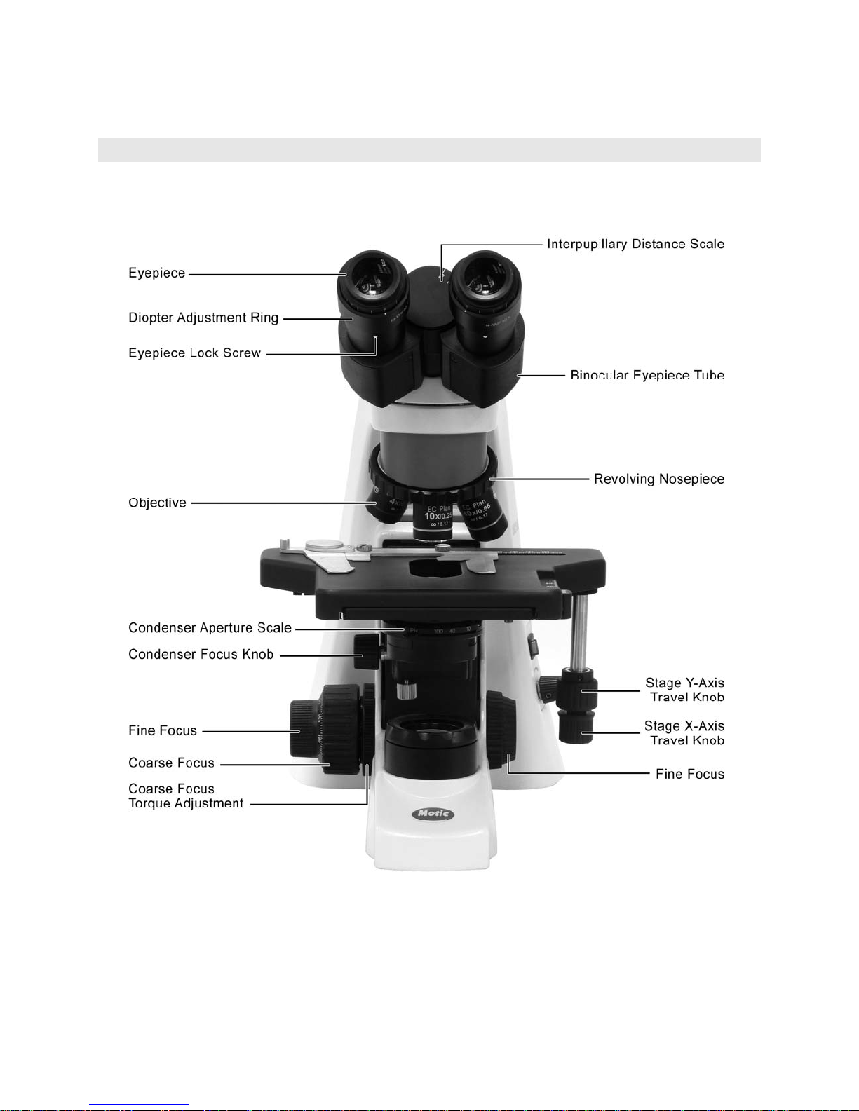
1. NOMENCLATURE
BA210E (Binocular)
 Loading...