

Motech LPS 305 User Manual

LPS 305
Linear Programmable Power Supply
User’s Manual

CONTENTS
1. GENERAL INFORMATION........................................................................................................... 1
1.1 Introduction ................................................................................................................................. 1
1.2 Safety Considerations ................................................................................................................ 1
1.3 Options ........................................................................................................................................ 3
1.4 Accessories ................................................................................................................................. 3
1.5 Output Isolation .......................................................................................................................... 3
1.6 Specifications .............................................................................................................................. 3
2. INSTALLATION ............................................................................................................................ 5
2.1 Introduction ................................................................................................................................. 5
2.2 Initial inspection .......................................................................................................................... 5
2.3 Location and cooling .................................................................................................................. 5
2.4 Input power requirements .......................................................................................................... 5
2.5 Line fuse ..................................................................................................................................... 5
3. GETTING STARTED ..................................................................................................................... 6
3.1 Front panel controls and output terminals............................................................................... 6
3.2 LCD display message ................................................................................................................ 8
REFER TO THE FIGURE B. ................................................................................................................... 8
3.3 Rear panel .................................................................................................................................. 9
4. OPERATION ............................................................................................................................... 10
4.1 Initial conditions ........................................................................................................................ 10
4.2 Control of output functions ...................................................................................................... 10
4.3 Enabling/Disabling the output .................................................................................................. 11
4.4 Overload protection of 5V or 3.3V output ............................................................................. 11
5. CALIBRATION ............................................................................................................................ 12
6. USER MAINTENANCE/SERVICE .............................................................................................. 15
6.1 Fuse Replacement ................................................................................................................... 15
6.2 In Case of Difficulties .............................................................................................................. 15
6.3 If the ERROR#2 shows on LCD ............................................................................................ 15
6.4 Using the RS-232-C Serial Interface ..................................................................................... 15


1
1. GENERAL INFORMATION
1.1 Introduction
This section contains a general description of your power supply as well as its performance
specifications. Information about options and accessories are also provided.
The TPS-3025 series has been designed and tested according to EN-61010-1, Safety requirement for
Electronic Measuring Apparatus.
1.2 Safety Considerations
SAFETY PRECAUTIONS
SAFETY NOTES
The following general safety precautions must be observed during all phases of operation, service,
and repair of this instrument. Failure to comply with these precautions or with specific warnings
elsewhere in this manual violates safety standards of design, manufacture, and intended use of the
instrument. The manufacturer assumes no liability for the customer’s failure to comply with these
requirements.
BEFORE APPLYING POWER
Verify that the power supply is set to match the available line voltage and the correct fuse is installed.
GROUND THE INSTRUMENT
This product is provided with a protective earth terminal. To minimize shock hazard, the instrument
chassis and cabinet must be connected to an electrical ground. The instrument must be connected to
the AC power supply mains through a three-conductor power cable, with the third wire firmly
connected to an electrical ground (safety ground) at the power outlet. For instruments designed to be
hard-wired to the AC power lines (supply mains), connect the protective earth terminal to a protective
conductor before any other connection is made. Any interruption of the protective (grounding)
conductor or disconnection of the protective earth terminal will cause a potential shock hazard that
could result in personal injury. If the instrument is to be energized via an external autotransformer for
voltage reduction, be certain that the autotransformer common terminal is connected to the neutral
(earthed pole) of the AC power lines (supply mains).
The RS232 (option) Ground is connected with chassis ground, and therefore the operator must take
care if the computer is also connected with other measuring devices prevent a short cut.
FUSES
Only fuses with the required rated current, voltage, and specified type (normal blow, time delay, etc.)
should be used. Do not use repaired fuses or shout circuited fuseholders. To do so could cause a
shock or fire hazard.
DO NOT OPERATE IN AN EXPLOSIVE ATMOSPHERE
Do not operate the instrument in the presence of flammable gases or fumes.
KEEP AWAY FROM LIVE CIRCUITS
Operating personnel must not remove instrument covers. Component replacement and internal
adjustments must be made by qualified service personnel. Do not replace components with power
cable connected.
!
2
Under certain conditions, dangerous voltages may exist even with power cable removed. To avoid
injuries, always disconnect power, discharge circuits and remove external voltage sources before
touching components.
DO NOT SERVICE OR ADJUST ALONE
Do not attempt internal service or adjustment unless another person, capable of rendering first aid and
resuscitation, is present.
DO NOT EXCEED INPUT RATINGS
This instrument must be connected to a properly grounded receptacle to minimize electric shock
hazard. Operate at line voltages or frequencies in excess of those stated on the data plate may cause
leakage currents in excess of 5.0mA peak.
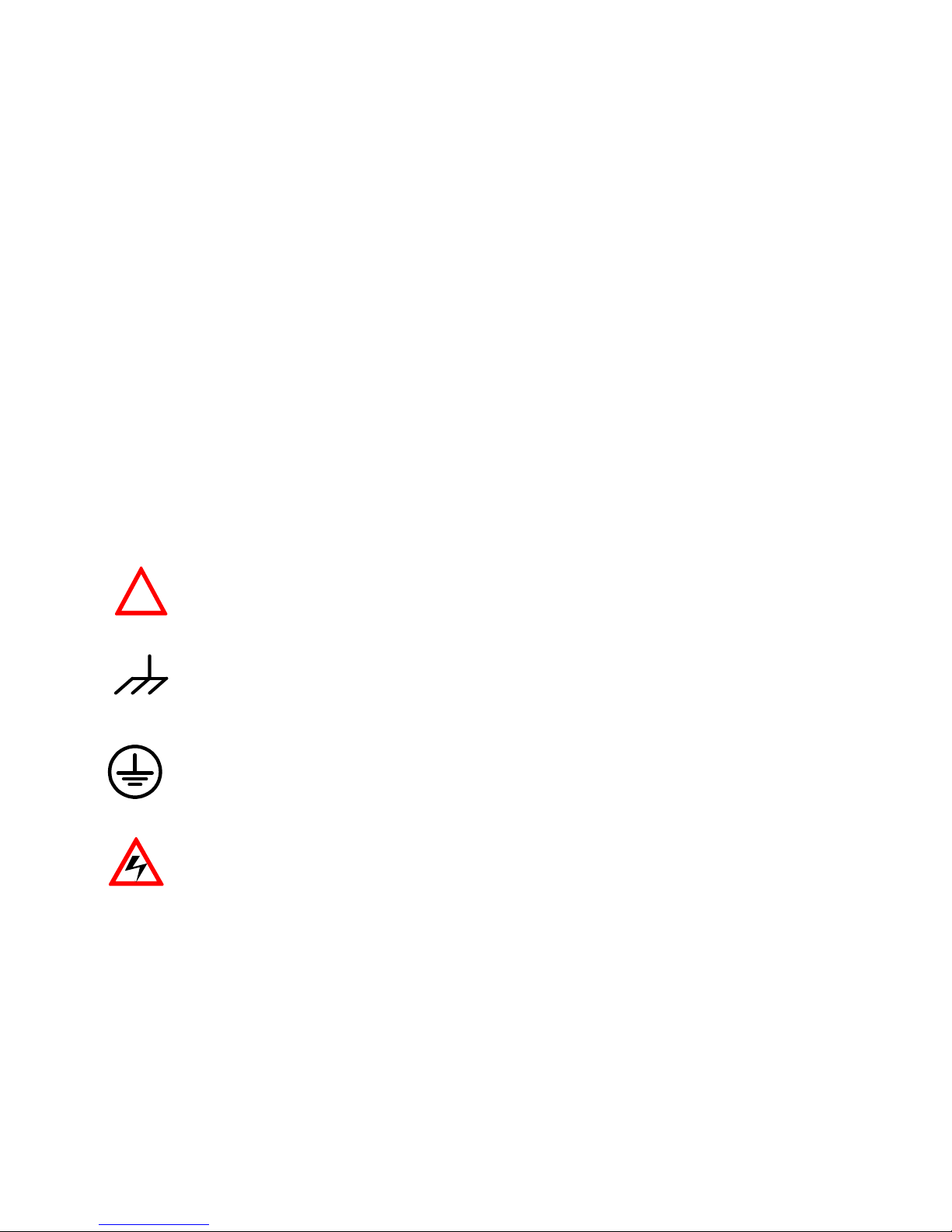
SAFETY SYMBOLS
WARNING The WARNING sign denotes a hazard. It calls attention to a procedure,
practice, or the like, which, if not correctly performed or adhered to, could
result in personal injury. Do not proceed beyond a WARNING sign until the
indicated conditions are fully understood and met.
CAUTION The CAUTION sign denotes a hazard. It calls attention to a procedure,
practice, or the like, which, if not correctly performed or adhered to, could
result in damage to or destruction of part or all of the product. Do not proceed
beyond a CAUTION sign until the indicated conditions are fully understood
and met.
Chassis ground symbol
Protective Conductor terminal
Caution, risk of electric shock
DO NOT SUBSTITUTE PARTS OR MODIFY INSTRUMENT
Because of the danger of introducing additional hazards, do not install substitute parts or perform any
unauthorized modification to the instrument. Return the instrument to a qualified dealers for service
and repair to ensure that safety features are maintained.
INSTRUMENTS WHICH APPEAR DAMAGED OR DEFECTIVE SHOULD BE MADE INOPERATIVE
AND SECURED AGAINST UNINTENDED OPERATION UNTIL THEY CAN BE REPAIRED BY
QUALIFIED SERVICE PERSONNEL.
!

3
1.3 Options
Options 01 determine which line voltage is set at the factory. This information is on the rear panel
label.
Option 01: RS-232 Interface
Option 02: Rack mount Shelf
1.4 Accessories
Power cable
Operation manual
Fuse
1.5 Output Isolation
The output of the power supply is isolated from earth ground. Either output terminal may be grounded
or the output may floated up to +/- 240 Vdc (including output voltage) from chassis ground
1.6 Specifications
TRIPLE OUTPUT LINEAR POWER SUPPLY UP TO 165 WATTS
Model
LPS 305
MAX. OUTPUT POWER
165 WATTS
OUTPUT VOLTAGE
Output Voltage
0 to +30V / 0 to -30V
Fixed 3.3V / 5V
Setting Resolution
10mV
Max. output voltage
+32V / -32V
Dual tracking
0 to 30V
Tracking deviation
20mV
OUTPUT CURRENT
Output Current
0 to +2.5A / 0 to -2.5A
3A
Setting Resolution
1mA
Max. output current
+3A / -3A
Current limited approx. 3.3A
Dual tracking
0 to 2.5A
Tracking deviation
5mA
CONSTANT VOLTAGE CHARACTERISTICS (at rated output : 2.5A )
Line regulation(for change of AC 10%)
1mV
5mV
Load regulation(for load change 0 100%)
2mV
10mV
Ripple/Noise rms
1.5mVrms
2mVrms

4
Ripple/Noise (p-p)
10mVp-p
20mVp-p
Transient Response
200s Typical
Temperature Coefficient
100ppm / ℃ Typical
CONSTANT CURRENT CHARACTERISTICS (at rated output : 2.5A )
Line regulation (for change of AC 10% )
15mA Typical
Load regulation (for change from short to
full load )
10mA Typical
Ripple/Noise rms
1mArms Typical
Ripple/Noise (p-p)
5mAp-p Typical
Temperature Coefficient
200 ppm / ℃ Typical
Display
2×16 LCD with backlit; Front Panel Status
Announciators with beeper
Voltage Accuracy*
( 0.2% of rdg +2 digits )
Current Accuracy*
( 0.5% of rdg +5 digits )
Common Mode Voltage
±240Vdc
Temperature ranges
Operating: 0℃ to 40℃, less than 80% RH;
Storage: -40℃ to 70℃, less than 80% RH
Dimensions (W × H × L)
8.4" × 5.2" × 15.7"
Weight
Approx. 18 lbs
Cooling
Fan Cooled
Power Source
AC 115V 10% OR 230V 10%, 47 to 63Hz
Current Consumption
2.88A / AC 115V or 1.48A / AC 230V
Fuse Rating
5AT / 250V for AC 115V, 2.5AT / 250V for AC 230V
Options
RS-232
Accessories
User’s manual, power cord, fuse
*For output less than 5% of rated output, add 5 digits to the accuracy specification
RS232 Interface capabilities:
1. RS232C DCE interface: 9-pin D-SUB connector.
2. Port configuration: asynchronous 2400 baud, 8 data bits, 1 stop bits, no parity.
 Loading...