

Page 1
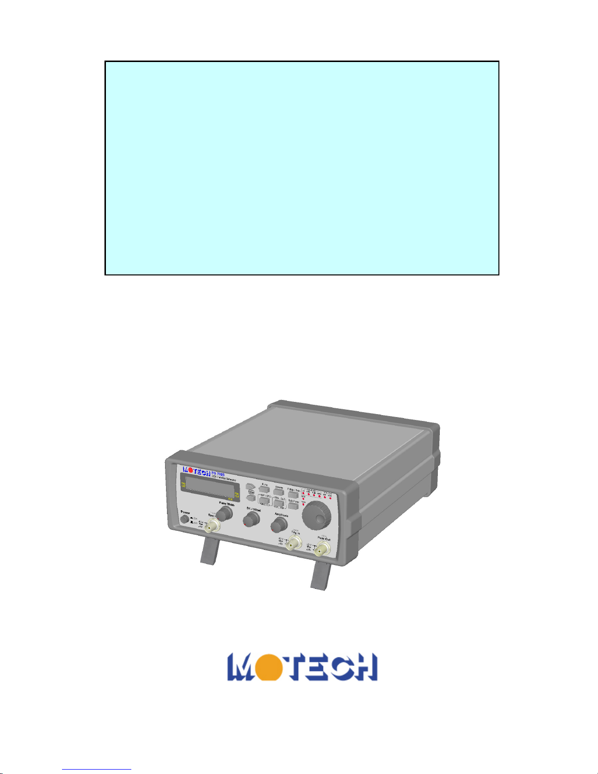
Operating Manual
FG 700S/F Series
Direct Digital Synthesis
Function Generator
Page 2

Page 3

SAFETY PRECAUTION
SAFETY CONSIDRATIONS
The Model FG700S/F series Direct Digital Synthesis Function Generator has been designed and tested
according to EN61010-1:2001 and EN61326:1997.
SAFETY PRECAUTIONS
SAFETY NOTES
The following general safety precautions must be observed during all phases of operation, service, and
repair of this instrument. Failure to comply with these precautions or with specific warnings elsewhere in
this manual violates safety standards of design, manufacture, and intended use of the instrument. The
manufacturer assumes no liability for the customer‘s failure to comply with these requirements.
BEFORE APPLYING POWER
Verify that the product is set to match the available line voltage is installed.
SAFETY SYMBOLS
Caution, risk of electric shock
Earth (ground) terminal
Equipment protected throughout by double insulation or
reinforced insulation
Caution (refer to accompanying documents)
Equipment complies with current EU directives
Protective earth (ground) terminal
Chassis terminal
Indoor use only
DO NOT SUBSTITUTE PARTS OR MODIFY INSTRUMENT
Because of the danger of introducing additional hazards, do not install substitute parts or perform any
unauthorized modification to the instrument. Return the instrument to a qualified dealer for service and
repair to ensure that safety features are maintained.
INSTRUMENTS WHICH APPEAR DAMAGED OR DEFECTIVE SHOULD BE MADE
INOPERATIVE AND SECURED AGAINST UNINTENDED OPERATION UNTIL THEY CAN
BE REPAIRED BY QUALIFIED SERVICE PERSONNEL.
Page 4

WARRANTY INFORMATION
ONE-YEAR-LIMITED WARRANTY
MOTECH INDUSTRIES INC. (MOTECH) warrants to the original user or purchaser that the unit is
free from any defects in material or workmanship for a period of one year from the date of purchase.
If any defect is discovered within the warranty period, MOTECH will repair or replace the unit, subject
to verification of the defect or malfunction, upon delivery or prepaid shipment to MOTECH.
This warranty does not apply to defects or to physical damage resulting from abuse, neglect, accident,
improper repair, alteration, or unreasonable use of the unit, resulting in (but not limited to) cracked or
broken case or parts, or to units damaged by excessive heat. Except upon initial purchase, this
warranty does not cover finish or appearance items nor does it cover items damaged in shipment to
MOTECH for repair or calibration.
To receive service under this warranty, you must include proof of purchase, including date and place of
purchase, (a copy of your purchase receipt) or MOTECH will not be responsible for repairs or
replacement of the unit under warranty.
Any applicable implied warranties, including warranties of merchant ability and fitness for a particular
use, are hereby limited to one year from the date of purchase. Consequential or incidental damages
resulting from loss of use, or from a breach of any applicable express or implied warranties are hereby
excluded.
The warranty is not to substitute all other agreements and warranties, general or special, express or
implied, and no representative or person is authorized to assume for us any other liability in connection
with the sale or use of this MOTECH product.
Page 5

Table of Content
1. Introduction ................................................................................................................................... 1
1.1 General .............................................................................................................................. 1
1.2 Key Features ...................................................................................................................... 1
1.3 Physical Description .......................................................................................................... 1
1.4 Specification ...................................................................................................................... 3
2. Operation....................................................................................................................................... 7
2.1 Keypad and Knob Description............................................................................................ 7
2.2 Opening Screen .................................................................................................................. 8
2.3 Setting Group Name........................................................................................................... 9
2.4 Adjust Frequency ............................................................................................................... 9
2.5 Select Waveform ................................................................................................................ 9
2.6 Frequency Sweep ............................................................................................................. 10
2.7 Output Attenuation ........................................................................................................... 13
2.8 Rotary Frequency Step Setting ......................................................................................... 13
2.9 Amplitude, Offset and Square Wave Pulse Width Display ................................................ 14
2.10 Trigger/Gate ..................................................................................................................... 16
2.11 Phase-Shift Keying (PSK) and Frequency-Shift Keying (FSK) Modulation...................... 16
2.12 Sub Function .................................................................................................................... 18
2.13 Notice of Operating .......................................................................................................... 22
Page 6

Page 7
1
1. Introduction
1.1 General
The Motech Model FG 700S/F series is a high-performance direct digital synthesize (DDS) function
generator with very low noise and distortion. Combined with the DDS technology, the FG 700S/F series
can output high accuracy and stable frequency to meet your test requirement of precision and accuracy.
The build-in trigger/gate function allows you to control the waveform generation by internal or external.
Also, the PSK and FSK modulation gives you the ability to generate such waveform for experiment or
communication purpose. The FG 700F series comes with AM/FM module and frequency counter to
make the function of this product more comprehensive.
1.2 Key Features
Direct digital synthesize multi-function generator
Sine, square, triangle, pulse, DC, synchronize and ramp up/ramp down (FG 700F series) output
Ultra low noise and low distortion (down to 1Mv peak signal)
PSK and FSK modulation
Digital setting of linear or logarithm sweep function
Trigger and gate function
AM/FM module (FG 700F series)
Frequency counter (FG 700F series)
1.3 Physical Description
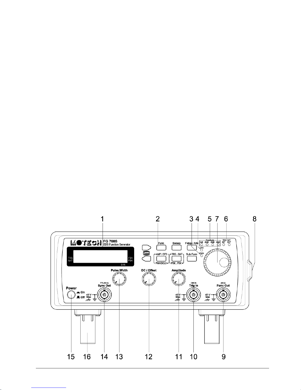
FG 700 Series Front Panel
Page 8
2
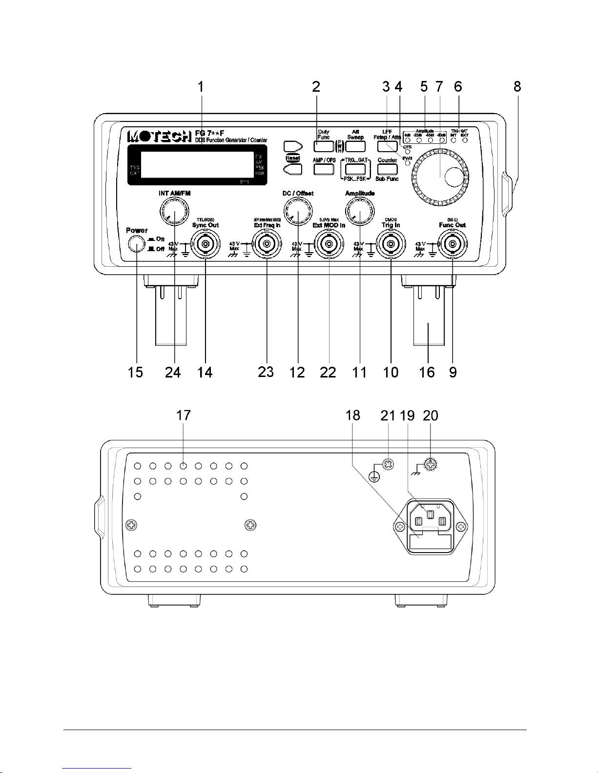
FG 700F Series Front Panel
Rear Panel
1 Liquid
Crystal Display
2
Keypad
3
Square Wave
Pulse Width Adjustment On/Off Indicator
4
Output Offset On/Off Indicator
5
Output Amplitude Attenuation Range Indicator
6
External/Internal indicator of Trigger/Gate or PSK/FSK
7
Rotary with Push Button
8
Handle
9 Function Output BNC Connector (50 output impedance)
Page 9

3
10
External input
BNC Connector
for Trigger/Gate and PSK/FSK (CMOS level)
11
Amplitude Adjustment Knob
12
DC/Offset Adjustment Knob
13
Square Wave Pulse Width Adjustment Knob
14 Sync Output Connector (TTL level with 50 output impedance)
15 Power Switch
16
Adjustable F
eet 17 Air
Ventilation
Holes
18
Power
-
line
Fuse Holder
19
Power
-
line
AC
Input
Socket
20
Chassis
Terminal
21 Protective Earth (Ground) Terminal
22
External Modulation Input (5.5Vp
Max.)
for AM/FM Function
23
External Frequency Input (5Vrms Max. @ 50
Ω) for Frequency Counter Function
24
Internal AM/FM
Adjustment Knob
1.4 Specification
FG 708S
Output Characteristics
a. Frequency Range : Sine, Square, Pulse and Sync Output : 100mHz ~ 8MHz
Triangle : 100mHz ~ 1MHz
b. Frequency Resolution : 100mHz or 6 digits display
c. Output Impedance : 50Ω 5%
d. Amplitude : 1mV to 20Vp-p (open-circuit)
0.5mV to 10Vp-p (50Ω load)
e. Amplitude Resolution :
[email protected]~9.99V ,1mV@10mV~99mV ,0.1mV@1mV~9.9
mV ,[email protected]~0.99mV (Depend on Attenuation)
f. Amplitude Accuracy : Typical 1% test at 1KHz 9Vp-p sine @ 50Ω load
g. Output Attenuation : 0, -20, -40 and -60 db
h. FUNC_OUT Self Protection : FUNC_OUT short circuit protection
Reverse voltage protection below 20Vpeak
i. DC Offset and DC Output : 10V at open-circuit, 5V at 50Ω load
j. DC Output Resolution :
10mV@±9.99V ,1mV@±99mV ,0.1mV@±9.9mV ,0.01mV@±
0.99mV (Depend on Attenuation)
k. DC Output Accuracy : 1% 5 counts (Amplitude Knob at Maximum Position)
l. Sine Wave Harmonic Distortion : DC ~ 100KHz < -55dBc typical
100KHz ~ 1MHz < -45dBc typical
1MHz ~ 8MHz < -35dBc typical
m. Spurious (non harmonic) : DC ~ 1MHz < -55dBc typical
n. Total Harmonic Distortion : DC ~ 100KHz < 0.3%
o. Square Wave : rise / fall time 15nS for 10Vp-p @ 50Ω load
overshoot < 5% of Vp for 10Vp-p @ 50Ω load
p. Pulse Generator : Frequency range : 100mHz ~ 8MHz
Amplitude : 0 ~ 10V / 0 ~ -10V / 10V
Duty cycle : 100mHz ~ 5MHz : 20% to 80%
5MHz ~ 8MHz : 40 % to 60%
q. Triangle Wave Linearity : 99% up to 100KHz
r. Sweep (Linear / Logarithmic) : Start frequency, stop frequency and sweep step
Sweep type : up, down and up-down
Page 10

4
s. Sync Output : Frequency range : 100mHz ~ 8MHz
Output level : low level 0.6V @ 50Ω
high level 1V @ 50Ω
Output impedance : 50Ω
Modulation Characteristics
a. FSK : Function : Sine, Square or Triangle
Frequency range : 100mHz ~ 8MHz
Internal rate : 400Hz / 1000Hz
Source : Internal / External
b. PSK : Function : Sine, Square or Triangle
Frequency range : 100mHz ~ 8MHz
Phase setting : 0.0000 to 360.0 degree
Internal rate : 400Hz / 1000Hz
Source : Internal / External
Trigger/Gate Characteristics
a. Trigger : Source : Manual (rotary push) / External
Main frequency setting : 100mHz ~ 100KHz
b. Gate : Source : Manual (rotary push) / External
Main frequency setting : 100mHz ~ 8MHz
General Characteristics
a. Power Source : AC 115V / 230V 10%, 50Hz / 60Hz
b. Temperature : 0ºC ~ 40ºC (Operation)
-20ºC ~ 70ºC (Storage)
c. Relative Humidity : up to 80%
d. Dimension : 235mm(W)× 95mm(H)×280mm(D)
e. Weight : 3Kg
f. Accessories : AC power cord 1
Operating Manual 1
FG 710F/720F
Output Characteristics
a. Frequency Range : Sine, Square, Pulse and Sync Output : 100mHz ~ 10M/20MHz
Triangle : 100mHz ~ 1MHz
Ramp Up, Ramp Down : 100mHz ~ 20KHz
b. Frequency Resolution : 100mHz or 6 digits display
c. Output Impedance : 50Ω ±5%
d. Amplitude : 1mV to 20Vp-p (open-circuit)
0.5mV to 10Vp-p (50Ω load)
e. Amplitude Resolution :
[email protected]~9.99V ,1mV@10mV~99mV ,0.1mV@1mV~9.9
mV ,[email protected]~0.99mV (Depend on Attenuation)
f. Amplitude Accuracy : Typical 1% test at 1KHz 9Vp-p sine @ 50Ω load
g. Output Attenuation : 0, -20, -40 and -60 db
h. FUNC_OUT Self Protection : FUNC_OUT short circuit protection
Reverse voltage protection below 20Vpeak
Page 11

5
i. DC Offset and DC Output : ±10V at open-circuit, ±5V at 50Ω load
j. DC Output Resolution :
10mV@±9.99V ,1mV@±99mV ,0.1mV@±9.9mV ,0.01mV@±
0.99mV (Depend on Attenuation)
k. DC Output Accuracy : 1% ± 5 counts (Amplitude Knob at Maximum Position)
l. Sine Wave Harmonic Distortion : DC ~ 100KHz < -55dBc typical
100KHz ~ 1MHz < -45dBc typical
1MHz ~ 10M/20MHz < -35dBc typical
m. Spurious (non harmonic) : DC ~ 1MHz < -55dBc typical
n. Total Harmonic Distortion : DC ~ 100KHz < 0.3%
o. Square Wave : rise / fall time 15nS for 10Vp-p @ 50Ω load
overshoot < 5% of Vp for 10Vp-p @ 50Ω load
p. Pulse Generator : Frequency range : 200mHz ~ 20KHz
20KHz ~ 400KHz
Amplitude : 0 ~ 10V / 0 ~ -10V / ±10V
Duty cycle : 200mHz ~ 20KHz : 0.1% ~ 99.9%
20KHz ~ 400KHz : 2% ~ 98%
q. Triangle Wave Linearity : 99% up to 100KHz
r. Sweep (Linear / Logarithmic) : Start frequency, stop frequency and sweep step
Sweep type : up, down and up-down
s. Sync Output : Frequency range : 100mHz ~ 10M/20MHz
Output level : low level 0.6V @ 50Ω
high level 1V @ 50Ω
Output impedance : 50Ω
Modulation Characteristics
a. FM : Modulation : Sine, Suqare or Triangle
Frequency range : 100mHz ~ 10KHz
Peak deviation : 4 ~ 5% of Max Frequency
Source : Internal/External
Internal source : 400Hz/1000Hz Sine Wave
External source : Any Waveform @ 5.5 Vpeak Max
b. AM : Modulation : Sine or Triangle
Modulation Depth : 0% ~ 100% (5%)
Source : Internal/External
Internal source : 400Hz/1000Hz Sine Wave
External source : Any Waveform @ 5.5 Vpeak Max
c. FSK : Function : Sine, Square or Triangle
Frequency range : 100mHz ~ 10M/20MHz
Internal rate : 400Hz / 1000Hz
Source : Internal / External
d. PSK : Function : Sine, Square or Triangle
Frequency range : 100mHz ~10M/20MHz
Phase setting : 0.0000 to 360.0 degree
Internal rate : 400Hz / 1000Hz
Source : Internal / External
Trigger/Gate Characteristics
a. Trigger : Source : Manual (rotary push) / External
Main frequency setting : 100mHz ~ 100KHz
b. Gate : Source : Manual (rotary push) / External
Page 12

6
Main frequency setting : 100mHz ~ 10M/20MHz
Frequency Counter
a. Range : 4Hz to 100MHz
b. Accuracy : ±5 counts
c. Resolution : 7 digits or (99.9999)
d. Low pass filter : Manual
e. Timebase accuracy : 50MHz±25ppm(23.5±5˚C)Optional TCXO Time Base Available
f. Input Attenuation : 0db,-20db
g. Sensitivity : 4Hz ~ 50MHz/-20dbm @ 50Ω typical
50MHz ~ 80MHz/-10dbm @ 50Ω typical
80MHz ~ 100MHz/-5dbm @ 50Ω typical
General Characteristics
a. Power Source : AC 115V / 230V 10%, 50Hz / 60Hz
b. Temperature : 0ºC ~ 40ºC (Operation)
-20ºC ~ 70ºC (Storage)
c. Relative Humidity : up to 80%
d. Dimension : 235mm(W)× 95mm(H)×280mm(D)
e. Weight : 3Kg
f. Accessories : AC power cord 1
Operating Manual 1
Page 13
7
2. Operation
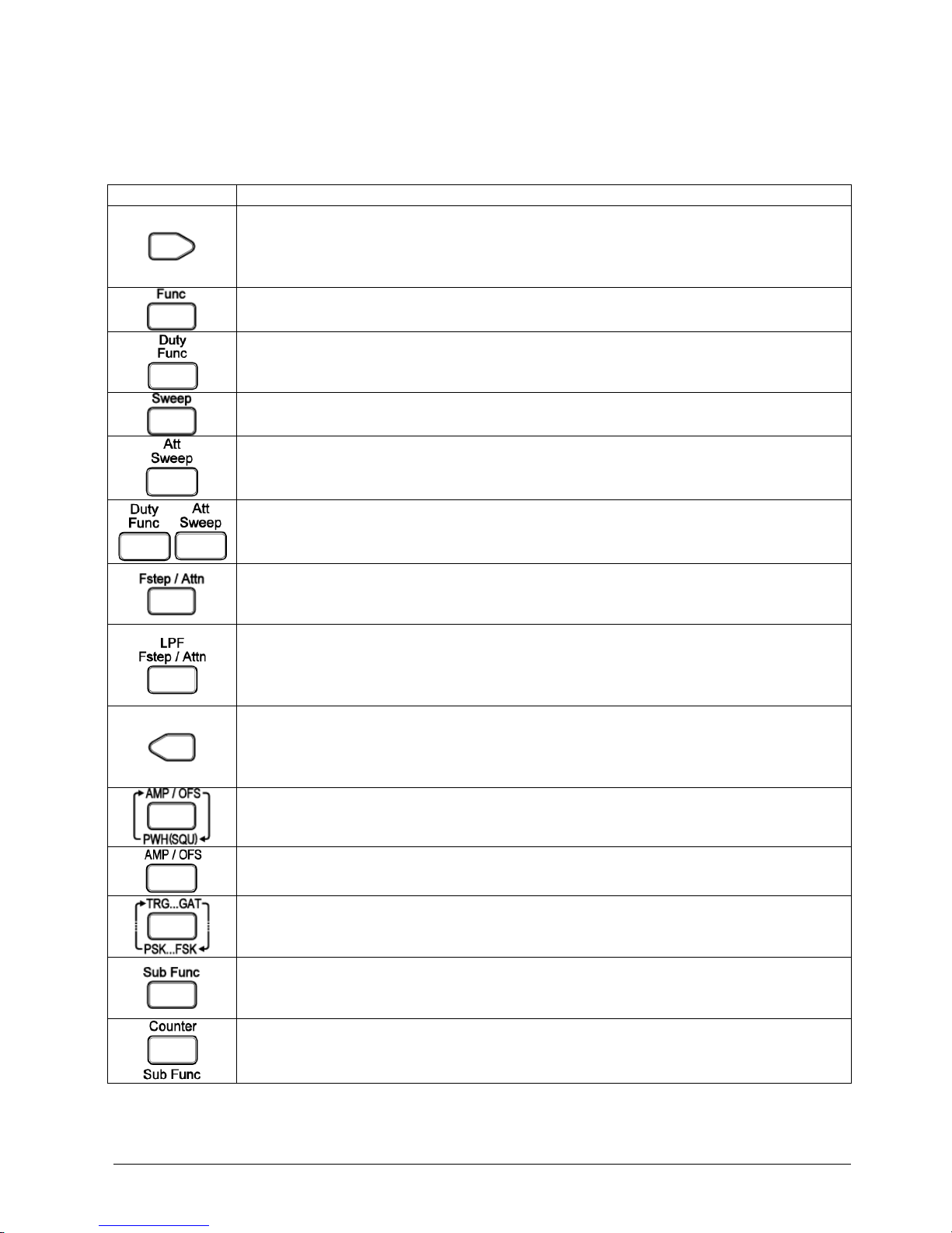
2.1 Keypad and Knob Description
Key and knob Function
Right Key (FG700S/F Series)
a. Change to the next selection.
b. In frequency editing, the frequency will x10 if the cursor is off.
c. In frequency editing, the cursor goes to right position if the cursor is on.
Function Key (FG700S Series)
a. Select the function output of sine, square, triangle or DC.
Function Key (FG700F Series)
a. Select the function output of sine, square, triangle, DC, ramp up or ramp down.
Sweep Key (FG700S Series)
a. Enter the sweep menu to select and set the linear or logarithm frequency sweep.
Sweep Key/Counter Attenuation Key (FG700F Series)
a. Enter the sweep menu to select and set the linear or logarithm frequency sweep.
b. In counter mode, select the attenuator on/off of the external counter input.
Both Key Pressed Simulteniously (FG700F Seires)
a. Enter the pulse width duty adjustment of square wave and adjust by rotary.
Frequency Step/Attenuation Key (FG700S Series)
a. Enter the attenuation menu to change the output attenuation.
b. Enter the frequency step menu to select and set the frequency step function.
Frequency Step/Attenuation Key/Counter LPF Key (FG700F Series)
a. Enter the attenuation menu to change the output attenuation.
b. Enter the frequency step menu to select and set the frequency step function.
c. In counter mode, select the low pass filter on/off.
Left Key (FG700S/F Series)
a. Change to the previous selection.
b. In frequency editing, the frequency will /10 if the cursor is off.
c. In frequency editing, the cursor goes to left position if the cursor is on.
Amplitude/Offset/Pulse Width Display Key (FG700S Series)
a. Select the display of amplitude, offset and pulse width of square wave.
Amplitude/Offset Key (FG700F Series)
Select the display of amplitude and offset.
Trigger/Gate and PSK/FSK key (FG700S/F Series)
a. Enter the trigger/gate menu to select and set the trigger/gate function.
b. Enter the PSK/FSK menu to select and set the PSK/FSK function.
Sub Function Key (FG700S Series)
a. Enter the sub function menu to select and set the sync output, pulse width of
square wave and offset function.
Sub Function/Counter Key (FG700F Series)
a. Enter the sub function menu to select and set the sync output, pulse width of
square wave, offset, AM, FM and counter function.
Page 14
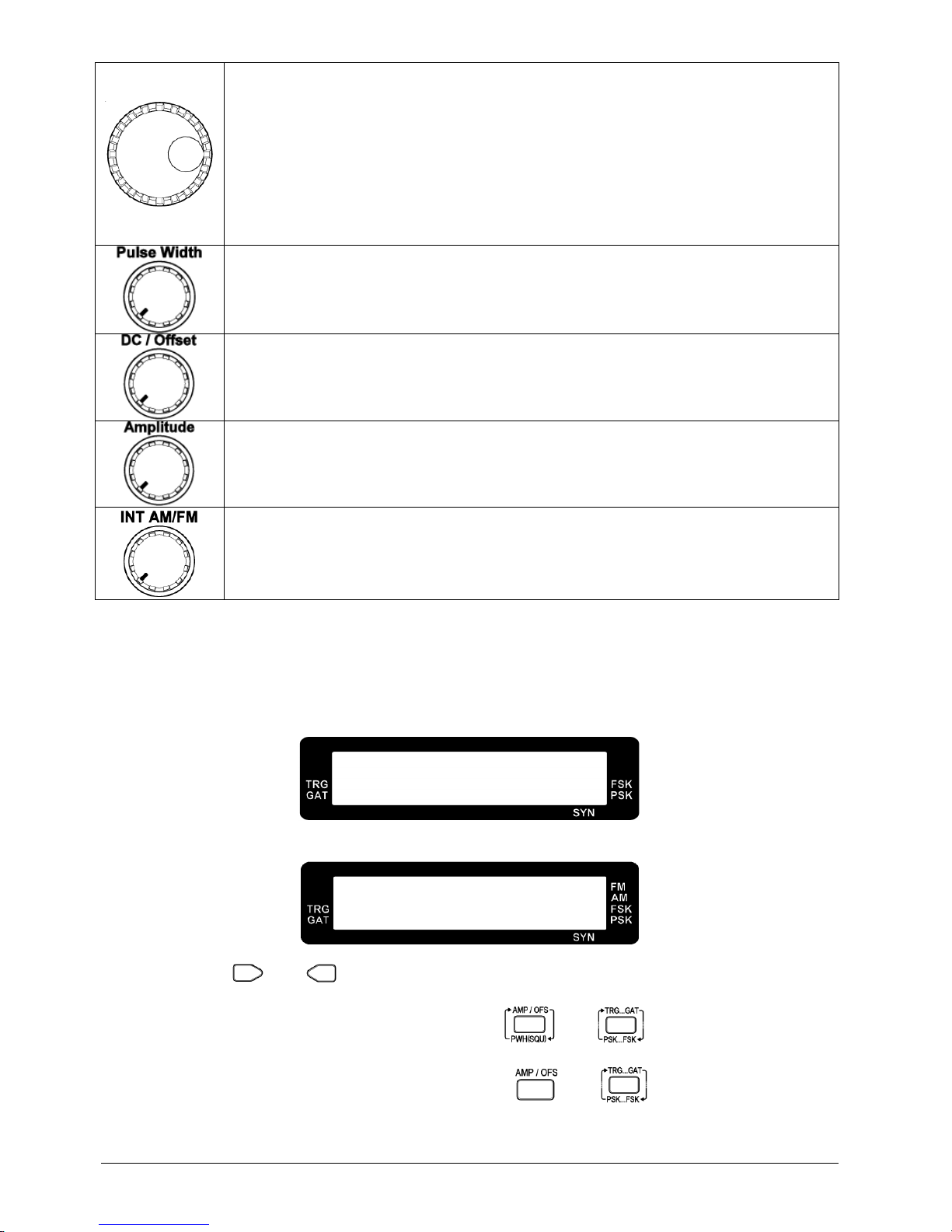
8
Rotary with Push button (FG700S/F Series)
a. Change to the next selection when turning clockwise.
b. Change to the previous selection when turning counterclockwise.
c. In frequency editing, turn clockwise to increase the frequency setting.
d. In frequency editing, turn counterclockwise to decrease the frequency setting.
e. When the cursor shows up in frequency editing, press the rotary push button to
cancel the cursor.
f. In rotary push trigger/gate function, press the rotary push button to generate
trigger/gate signal manually.
Pulse Width Adjustment Knob (FG700S Series)
a. Adjust the pulse width of the square wave.
DC/Offset Adjustment Knob (FG700S/F Series)
a. Adjust the DC level if the function output is set to DC.
b. Adjust the offset level if the output offset is on.
Pulse Width Adjustment Knob (FG700S/F Series)
a. Adjust the amplitude of the function out.
Internal AM/FM Adjustment Knob (FG700F Series)
a. Adjust the internal AM/FM modulation factor output.
2.2 Opening Screen
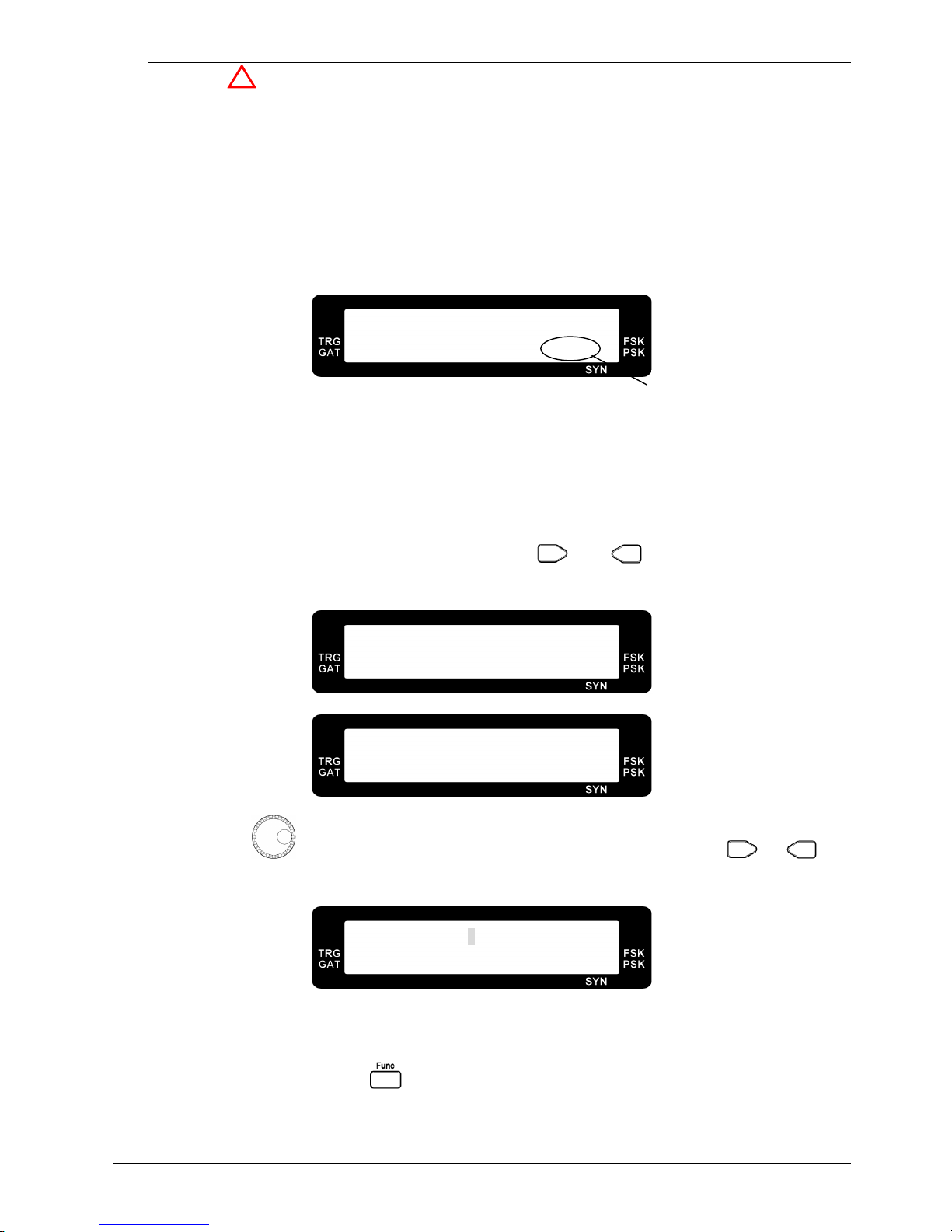
Connect the power cord and turn on the function generator.
FG700S Series
F G - 7 0 0 S
V e r s i o n : x . x x
FG700FSeries
F G - 7 0 0 F
V e r s i o n : x . x x
a. Press the and together to reset the function generator. This reset function sets the
function generator to default of 1KHz sine wave output at 20dB attenuation amplitude.
b. To turn off the beep of the keypad, please press and keys together for FG700S
series.
c. To turn off the beep of the keypad, please press
and key together for FG700F
series.
Page 15
9
Warning
Please make sure that the correct power rating feeds to the function generator. If the higher voltage
(230V) feeds to 115V version of function generator, the chance of damage the function generator
may happen and the fuse will blow. Please use the following rating of fuse for replacement.
115V version function generator : 0.5A/250V fuse (slow blow)
230V version function generator : 250mA/250V fuse (slow blow)
2.3 Setting Group Name
L I N : 4 . 0 0 0 2 K H z
S
WE E P
L I N S W 1
a. The setting group name is to show which parameter is set currently. For example, SW1 sets the
sweep mode of linear or logarithm, SW2 sets the type of sweep and SW3 sets the sweep start
frequency, etc.
2.4 Adjust Frequency
a. When the cursor does not appear on the LCD, use and key to adjust frequency x10
and /10.
F R Q : 1 0 . 0 0 0 0 K H z
A M P : 1 . 0 0 V S I N
F R Q : . 1 0 0 0 K H z
A M P : 1 . 0 0 V S I N
b. Adjust the to make the cursor appear and to change the frequency, use or key
to change the cursor position right or left. To cancel the cursor, please press the rotary button.
F R Q : 1 . 0 1 0 0 K H z
A M P : 1 . 0 0 V S I N
2.5 Select Waveform
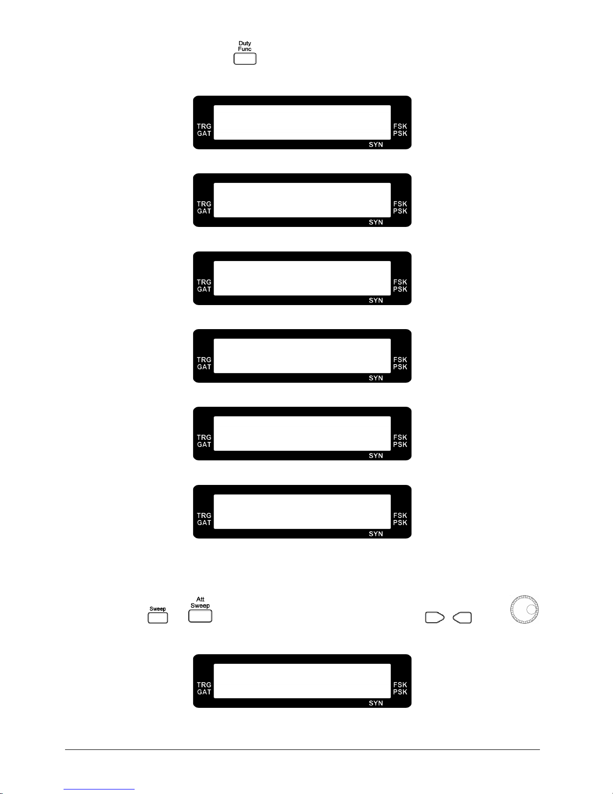
a. In FG708S series, press the key to select output waveform. There are four waveforms to be
selected (sine, square, triangle and DC).
Setting Group Name
Page 16
10
b. In FG708F series, press the key to select output waveform. There are six waveforms to be
selected (sine, square, triangle, ramp up, ramp down and DC).
F R Q : 1 . 0 0 0 0 K H z
A M P : 1 . 0 0 V S I N
Sine Wave Output
F R Q : 1 . 0 0 0 0 K H z
A M P : 1 . 0 0 V S Q U
Square Wave Output
F R Q : 1 . 0 0 0 0 K H z
A M P : 1 . 0 0 V T R I
Triangle Wave Output
F R Q : 1 . 0 0 0 0 K H z
A M P : 1 . 0 0 V R U P
Ramp Up Output
F R Q : 1 . 0 0 0 0 K H z
A M P : 1 . 0 0 V R D W
Ramp Down Output
F R Q : - - - - - - - - K H z
A M P : - 2 3 m V D C
DC Function Output
2.6 Frequency Sweep
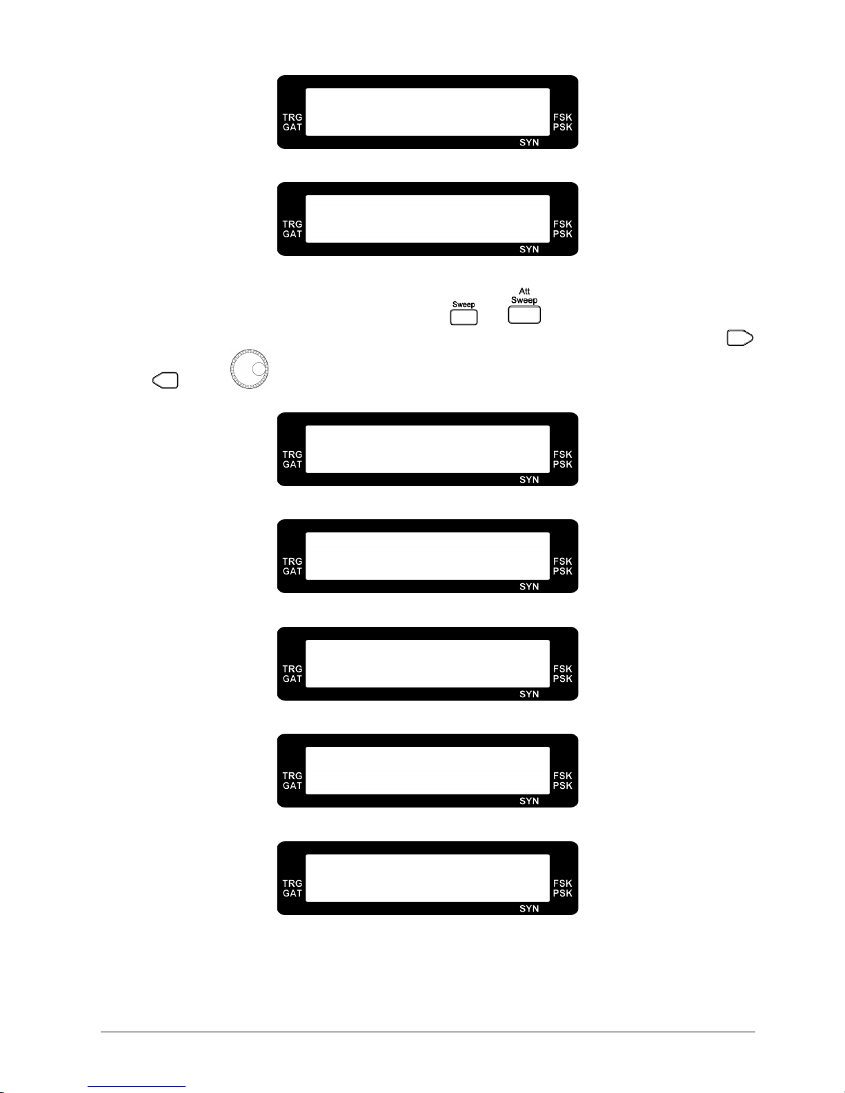
a. Press the or key to enter the sweep selection menu. Use , key or
to select linear or logarithm frequency sweep.
F R Q : 1 . 0 0 0 0 K H z
S
WE E P
O F F S
W1
Frequency Sweep Off
Page 17
11
L I N : 4 . 0 0 0 2 K H z
S
WE E P
L I N S W 1
Linear Frequency Sweep
L O G : 4 . 0 0 0 2 K H z
S
WE E P
L O G S W 1
Logarithm Frequency Sweep
b. When linear or logarithm is selected, press the or key to select the type of sweep,
sweep start frequency, sweep stop frequency and sweep step frequency or ratio. Use the ,
key or to select the desired sweep type or frequencies.
L I N : 4 . 0 0 0 2 K H z
T S W U p S W 2
Type of Sweep : Up
L I N : 4 . 0 0 0 2 K H z
T S W U p D o w n S W 2
Type of Sweep : Up/Down
L I N : 4 . 0 0 0 2 K H z
T S W D o w n S W 2
Type of Sweep : Down
S T A : 5 0 . 0 H z
S w e S t a r S e t S W 3
Sweep Start Frequency Setting
S T O : 8 . 0 0 0 0 0 M H z
S w e S t o p S e t S W 4
Sweep Stop Frequency Setting
Page 18
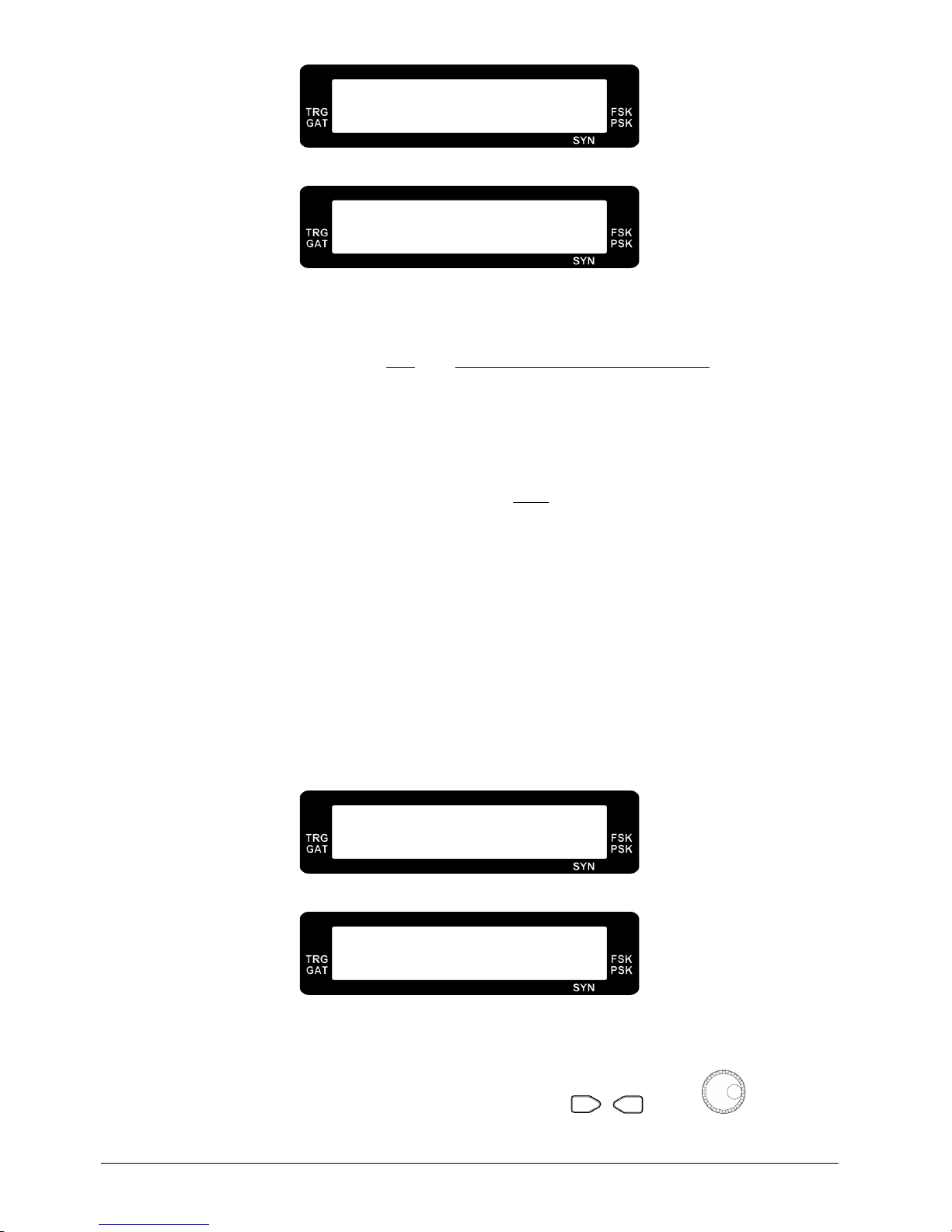
12
L I N : 1 0 . 0 0 0 0 K H z
S w e S t e p S e t S
W5
Linear Sweep Step Frequency Setting
L O G : 1 0 . 0
S w e S t e p S e t S
W6
Logarithm Sweep Step Ratio Setting
The actual logarithm sweep step ratio is calculated by following equation:
1000
Setting Ratio Step Sweep Logarithm
1
F
F
Ratio Actual
n
1n
+==
+
For Example, if the logarithm sweep step ratio setting is set to 5 and the
n
F
is 1000Hz, the
actual ratio is the following:
005.1
1000
5
1 Ratio Actual =+=
The
1nF+
,
2nF+
and 3nF+ are the following:
1005Hz1000Hz1.005FRatio ActualF
n1n
=×=×=
+
1010.025Hz1005Hz1.005FRatio ActualF
1n2n
=×=×=
++
5Hz1015.075121010.025Hz1.005FRatio ActualF
2n3n
=×=×=
++
Note : The maximum value of the logarithm sweep step ratio setting is 10.0 and the minimum
value of the logarithm sweep step ratio setting is 0.0001.
L I N : 1
S w e T i m e S e t S
W7
Linear Sweep Time Setting
L O G : 1
S w e T i m e S e t S
W7
Logarithm Sweep Time Setting
The sweep time sets the delay time between two frequencies step. It is set from 1 to 1000. The
higher value will put longer delay of two frequencies step.
c. After finishing the linear or logarithm sweep setting, the , key or can be used
to select sine, square, triangle, ramp up (FG700F series) or ramp down (FG700F series) output
Page 19
13
waveform.
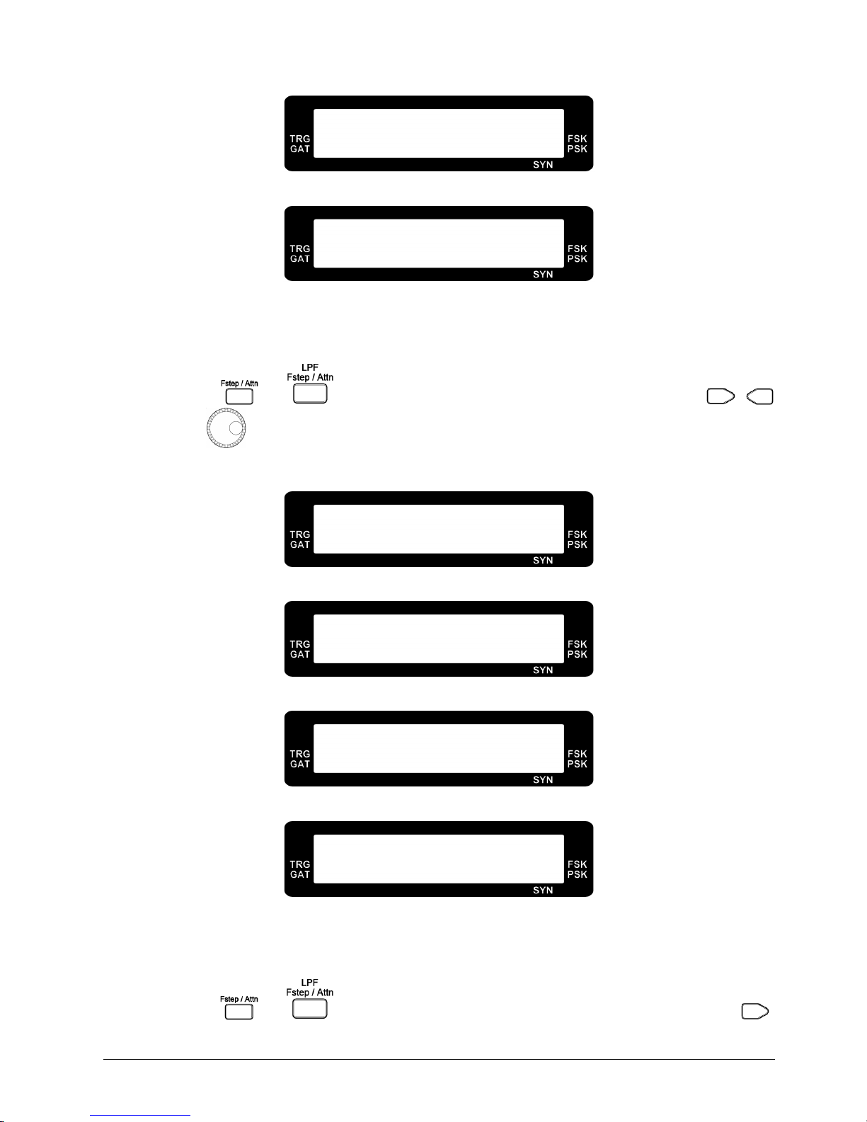
L I N : 4 . 0 0 0 0 2 M H z
A M P : 1 . 0 0 V S I N
Linear Sweep
L O G : 4 . 0 0 0 0 2 M H z
A M P : 1 . 0 0 V S I N
Logarithm Sweep
2.7 Output Attenuation
a. Press the or key once to enter the attenuation select menu. Use the ,
key or to select the output attenuation of 0, 20, 40 and 60 dB. The corresponding
amplitude indicator will show the current output attenuation setting.
F R Q : 1 . 0 0 0 0 K H z
A T N 0 D B A T 1
0dB Output Attenuation
F R Q : 1 . 0 0 0 0 K H z
A T N 2 0 D B A T 1
20dB Output Attenuation
F R Q : 1 . 0 0 0 0 K H z
A T N 4 0 D B A T 1
40dB Output Attenuation
F R Q : 1 . 0 0 0 0 K H z
A T N 6 0 D B A T 1
60dB Output Attenuation
2.8 Rotary Frequency Step Setting
a. Press the or key twice to enter the frequency step setting menu. Use the ,
Page 20

14
key or to select the
default
or
manual
frequency step of rotary up/down
adjustment.
F R Q : 1 . 0 0 0 0 K H z
F S t e p D e f a A T 2
Default Frequency Step
F R S : 1 . 0 0 0 0 K H z
F S t e p M a n u A T 2
Manual Frequency Step
b. When frequency step sets to manual, press the key again to adjust the frequency step
setting. Use the , key or to adjust this setting.
F R S : 1 . 0 0 0 0 K H z
F r q S t e p S e t A T 3
Note : Once the frequency step is set to manual, the output frequency can be controlled by the
,
key or
.
2.9 Amplitude, Offset and Square Wave Pulse Width Display
a. In FG700S series, press the key to show the amplitude, offset and pulse width of the
square wave.
b. In FG700F series, press the key to show the amplitude, offset.
c. To adjust the amplitude, please turn the knob.
F R Q : 1 . 0 0 0 0 K H z
A M P : 1 . 0 0 V S I N
Amplitude Display
d. To adjust the DC offset, please make sure the DC offset is set to on in the sub function menu
(SB3). Turn the
knob to adjust.
Page 21
15
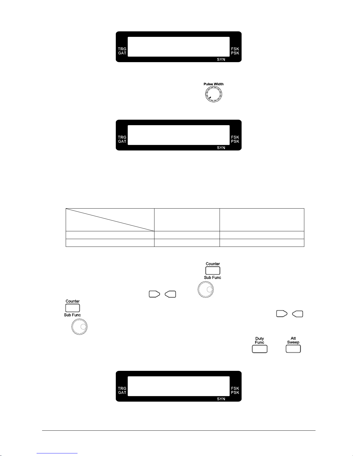
F R Q : 1 . 0 0 0 0 K H z
O F S : . 0 0 m V S I N
Offset Display
e. To adjust the pulse width in FG700S series, please select the square waveform first and set the
pulse width on in sub function menu (SB2). Turn the knob to adjust.
F R Q : 1 . 0 0 0 0 K H z
P
WH :
5 0 % S Q U
Square Wave Pulse Width Display
Note : The square wave pulse width display can be seen only if the square wave pulse width
adjustment is turned on in sub function.
f. The pulse width display value will show below or over if the pulse width is under or above the
following values in FG708S:
Frequency Range
Display Shows
0.1Hz ~ 5.99999MHz 6.00000MHz ~ 8.00000MHz
BELOW
< 18% < 34%
OVER
> 81% > 75%
g. To adjust the pulse width in FG700F Series, please select the square wave first and set the pulse
width on in the sub function menu (SB4). Press the key to select SB5 menu to set the
pulse width frequency. Use the , key or to set the frequency. Then, press the
key the select SB6 menu for the pulse width duty setting. Also, use the , key
or to set the duty.
h. To quickly enter the pulse width duty setting, please press the and key
simultenously.
P
WH : 1 . 0 0 0 0
K H z
5 0 0 . 0 u S S B 5
Pulse Width Frequency Setting
Page 22
16
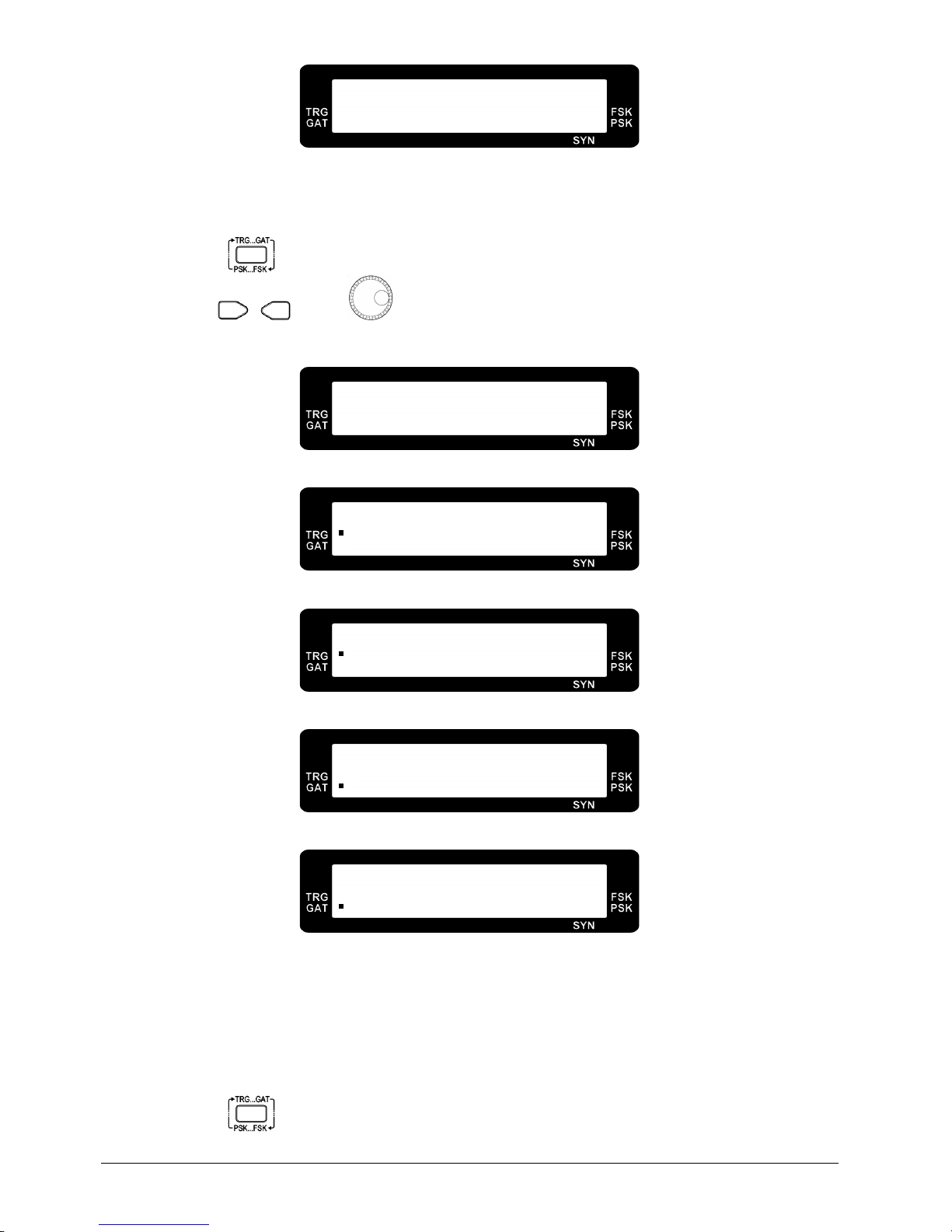
D T Y : 5 0 . 0 %
5 0 0 . 0 u S S B 6
Pulse Width Duty Setting
2.10 Trigger/Gate
a. Press the key to enter the trigger/gate selection menu.
b. Use the , key or to select
external trigger, rotary push trigger, external gate
and
rotary push gate
. The corresponding internal or external indicator will show up.
F R Q : 1 . 0 0 0 0 K H z
T R G O F F T M 2
Trigger/Gate Off
F R Q : 1 . 0 0 0 0 K H z
E X T
T R G T M 2
External Trigger
F R Q : 1 . 0 0 0 0 K H z
R O T P
T R G T M 2
Rotary Push Trigger
F R Q : 1 . 0 0 0 0 K H z
E X T
G A T T M 2
External Gate
F R Q : 1 . 0 0 0 0 K H z
R O T P
G A T
Rotary Push Gate
2.11 Phase-Shift Keying (PSK) and Frequency-Shift Keying (FSK)
Modulation
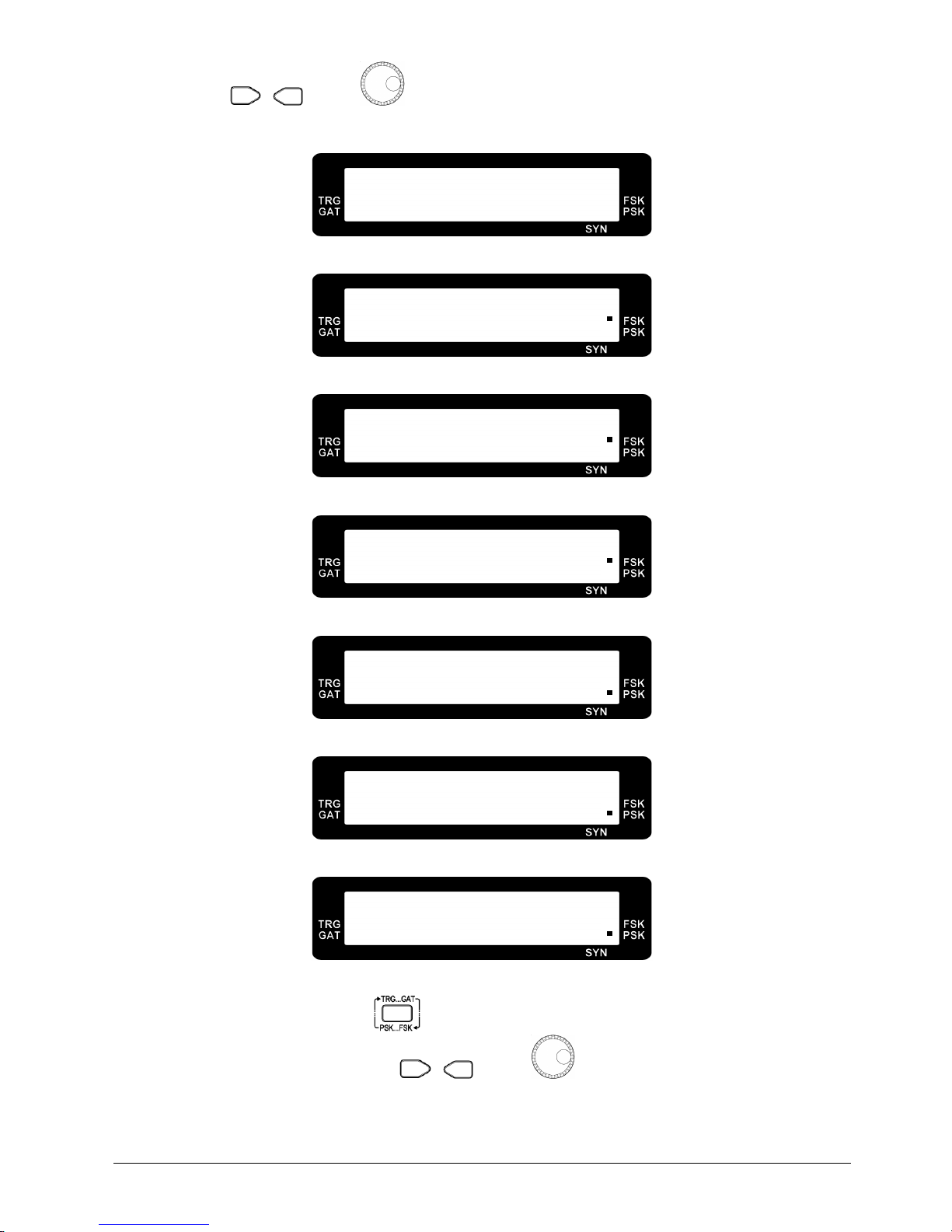
a. Press the key twice to enter the PSK/FSK modulation selection menu.
Page 23
17
b. Use the , key or to select
PSK 1KHz, PSK 400Hz, PSK external, FSK 1KHz
,
FSK 400Hz
and
FSK external
. The corresponding internal or external indicator will show up.
F R Q : 1 . 0 0 0 0 K H z
P F M O F F T M 3
PSK/FSK Off
F R Q : 1 . 0 0 0 0 K H z
P F M F s k E x t T M 3
FSK External
F R Q : 1 . 0 0 0 0 K H z
P F M F s k 4 0 0 T M 3
FSK 400Hz
F R Q : 1 . 0 0 0 0 K H z
P F M F s k 1 K T M 3
FSK 1KHz
F R Q : 1 . 0 0 0 0 K H z
P F M P s k E x t T M 3
PSK External
F R Q : 1 . 0 0 0 0 K H z
P F M P s k 4 0 0 T M 3
PSK 400Hz
F R Q : 1 . 0 0 0 0 K H z
P F M P s k 1 K T M 3
PSK 1KHz
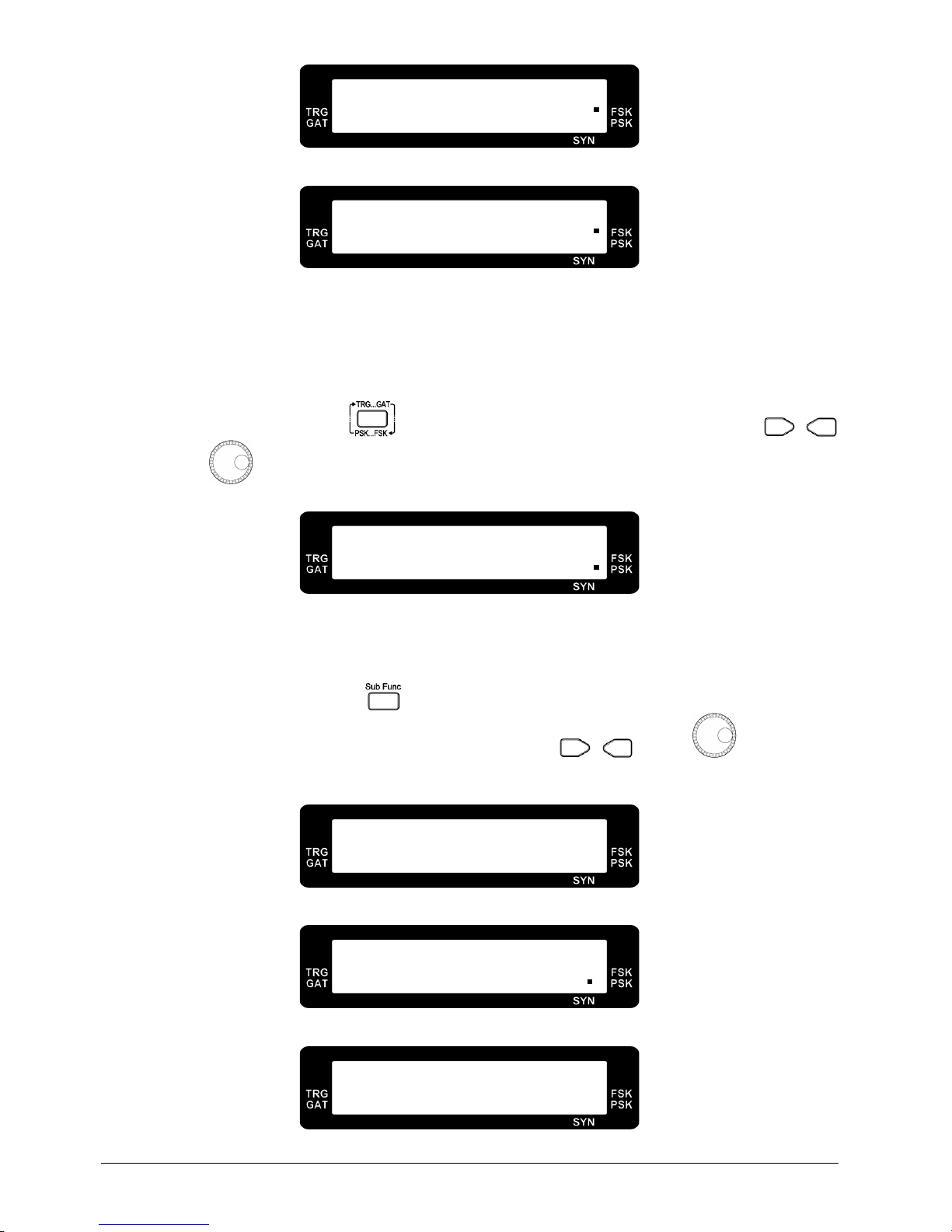
c. If FSK turns on, press the key to enter the FSK frequency register 1 and frequency
register 0 setting menu. Use the , key or to set the desired FSK frequencies.
Page 24
18
F R Q : 1 . 0 0 0 0 K H z
F s k F r q 1 S e t T M 4
FSK Frequency 1 Setting
F R Q : 1 . 0 0 0 0 K H z
F s k F r q 0 S e t T M 5
FSK Frequency 0 Setting
Note : The FSK frequency register 1 setting range is from 12.0Hz to maximum output
frequency of the function generator or 12.000MHz. The FSK frequency register 0
setting range is from 0.100Hz to maximum output frequency of the function
generator or 12.0000MHz.
d. If PSK turns on, press the key to enter the PSK phase setting menu. Use the ,
key or
to set the desired PSK phase.
D E G : 9 0 . 0 0
P S K P h s S e t T M 6
PSK Phase Setting
2.12 Sub Function
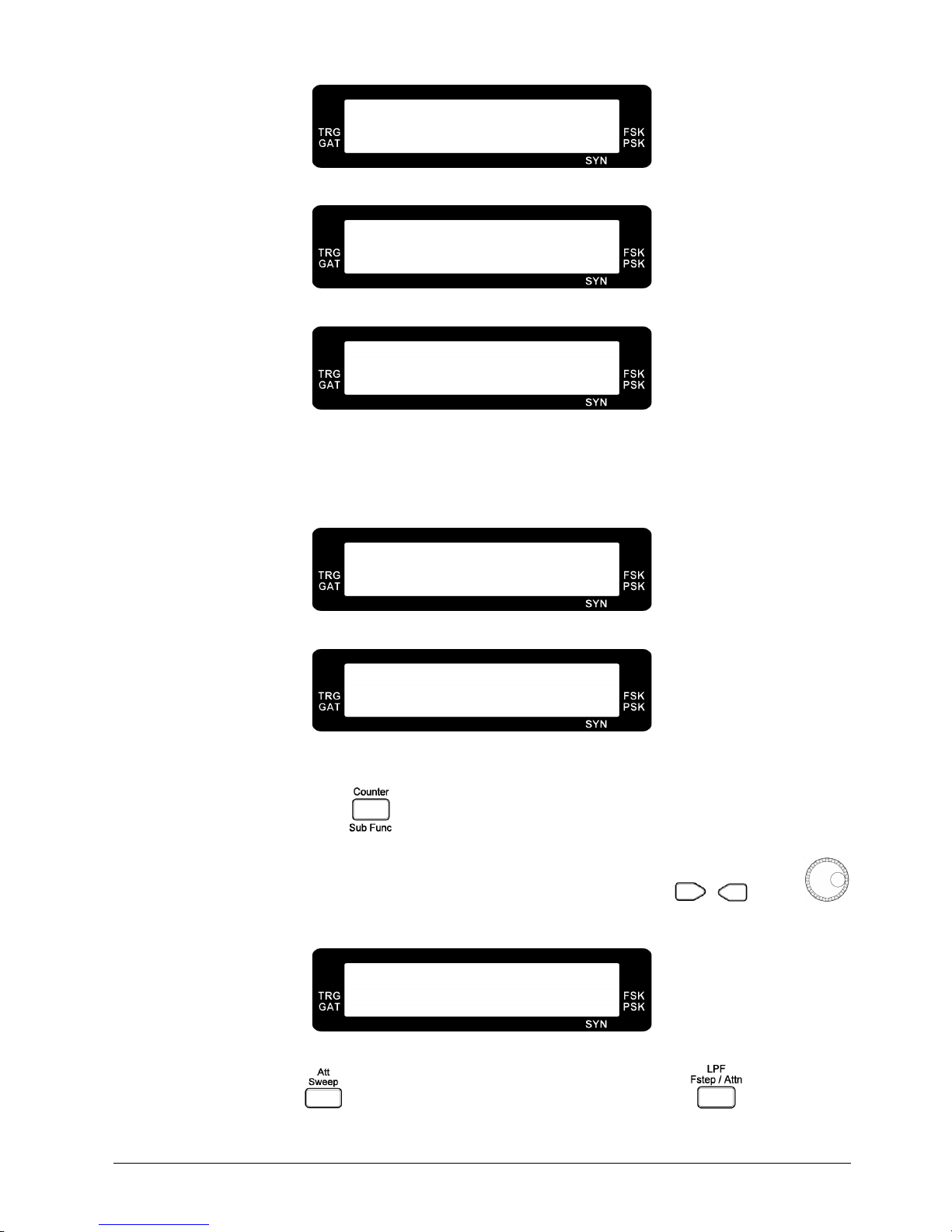
a. In FG700S series, press the key to select
sync output on/off, square wave pulse width
adjustment on/off
and
output offset on/off
. Use the , key or to select the
desired on/off setting.
F R Q : 1 . 0 0 0 0 K H z
S Y N O F F S B 1
Sync Output Off
F R Q : 1 . 0 0 0 0 K H z
S Y N O N S B 1
Sync Output On
F R Q : 1 . 0 0 0 0 K H z
P
WH
O F F S B 2
Square Wave Pulse Width Adjustment Off
Page 25
19
F R Q : 1 . 0 0 0 0 K H z
P
WH
P o s S B 2
Square Wave Pulse Width Adjustment On and Output Positive Pulse
F R Q : 1 . 0 0 0 0 K H z
P
WH
N e g S B 2
Square Wave Pulse Width Adjustment On and Output Negative Pulse
F R Q : 1 . 0 0 0 0 K H z
P
WH
B o t h O n S B 2
Square Wave Pulse Width Adjustment On and Output Positive and Negative Pulse
Note : The square wave pulse width adjustment on/off selection will show up in the sub
function only if the output select to square wave. If the pulse width adjustment is on,
the pulse width indicator will show up.
F R Q : 1 . 0 0 0 0 K H z
O F F S E T O F F S B 3
Output Offset Off
F R Q : 1 . 0 0 0 0 K H z
O F F S E T O N S B 3
Output Offset On
Note : If the output offset is on, the offset indicator will show up.
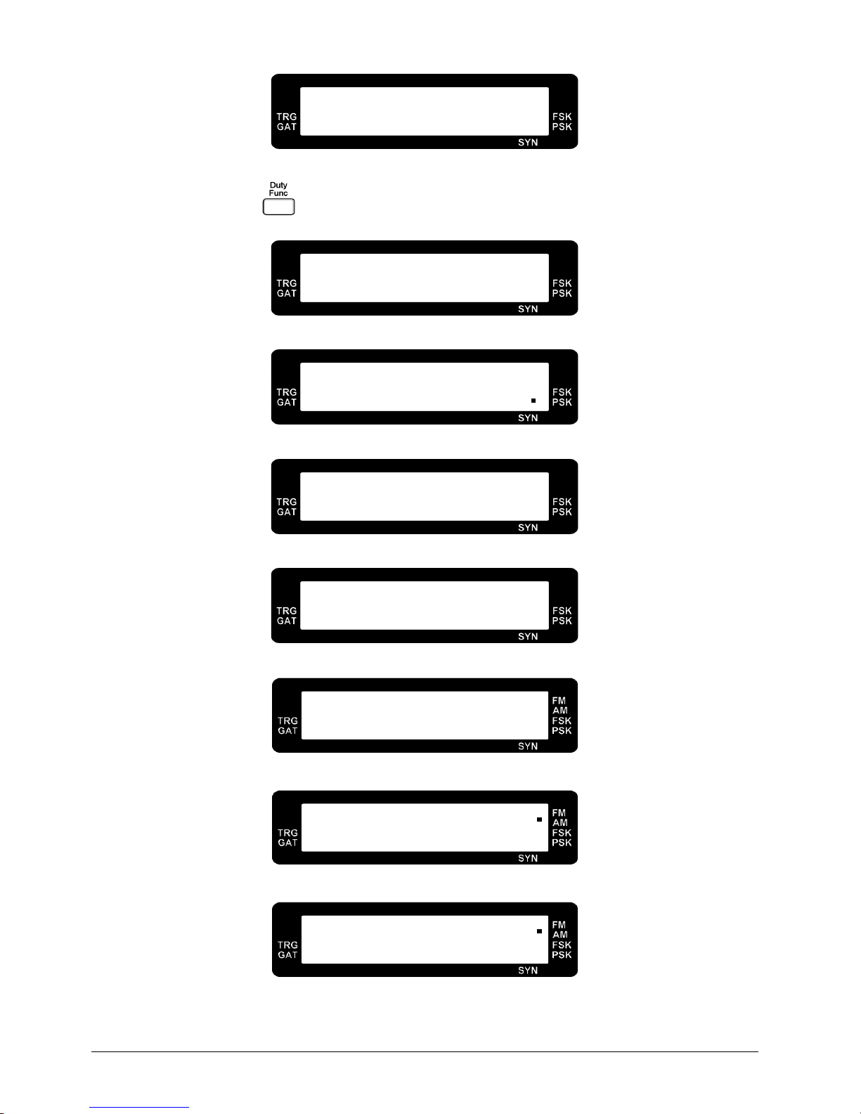
b. In FG700F series, press key to select
counter display and setting, sync output on/off
,
output offset on/off, AM on/off, square wave pulse width adjustment on/off, pulse width
frequency setting, pulse width duty setting
and
FM on/off
. Use the , key or
to select the desired on/off setting.
L R G : 1 . 0 0 0 0 K H z
A T T : + L P F :
Counter Display and Attenuator/ LPF Setting
Note : Use the
key to set the attenuator on/off (+/-). Use the key to set the
low pass filter on/off (+/-).
Page 26
20
1 9 . 6
%
D u t y C y
l e
Duty Cycle Measurement
Note : Use the
key measure the duty cycle of the external input signal.
F R Q : 1 . 0 0 0 0 K H z
S Y N O F F S B 1
Sync Output Off
F R Q : 1 . 0 0 0 0 K H z
S Y N O N S B 1
Sync Output On
F R Q : 1 . 0 0 0 0 K H z
O F F S E T O F F S B 2
Output Offset Off
F R Q : 1 . 0 0 0 0 K H z
O F F S E T O N S B 2
Output Offset On
F R Q : 1 . 0 0 0 0 K H z
A M O F F S B 3
AM Off
F R Q : 1 . 0 0 0 0 K H z
A M 4 0 0 H z S B 3
AM On, Internal 400Hz Source
F R Q : 1 . 0 0 0 0 K H z
A M 1 0 0 0 H z S B 3
AM On, Internal 1000Hz Source
Page 27
21
F R Q : 1 . 0 0 0 0 K H z
A M E X T E R N S B 3
AM On, External Source
F R Q : 1 . 0 0 0 0 K H z
P
WH
O F F S B 4
Square Wave Pulse Width Adjustment Off
F R Q : 1 . 0 0 0 0 K H z
P
WH
P o s S B 4
Square Wave Pulse Width Adjustment On and Output Positive Pulse
F R Q : 1 . 0 0 0 0 K H z
P
WH
N e g S B 4
Square Wave Pulse Width Adjustment On and Output Negative Pulse
F R Q : 1 . 0 0 0 0 K H z
P
WH
B o t h O n S B 4
Square Wave Pulse Width Adjustment On and Output Positive and Negative Pulse
F R Q : 1 . 0 0 0 0 K H z
P
WH
P u l s e S B 4
Square Wave Pulse Width Adjustment On and Output Pulse
Note : The square wave pulse width adjustment on/off selection will show up in the sub
function only if the output select to square wave. If the pulse width adjustment is on,
the pulse width indicator will show up.
P
WH : 1 . 0 0 0 0
K H z
5 0 0 . 0 u S S B 5
Pulse Width Frequency Setting
D T Y : 5 0 . 0 %
5 0 0 . 0 u S S B 6
Pulse Width Duty Setting
Page 28
22
F R Q : 1 . 0 0 0 0 K H z
F M O F F S B 7
FM Off
F R Q : 1 . 0 0 0 0 K H z
F M 4 0 0 H z S B 7
FM On, Internal 400Hz Source
F R Q : 1 . 0 0 0 0 K H z
F M 1 0 0 0 H z S B 7
FM On, Internal 1000Hz Source
F R Q : 1 . 0 0 0 0 K H z
F M E X T E R N S B 7
FM On, External Source
2.13 Notice of Operating
a. For Waveform Measurement :
•
The FG 700S/F series Func Out output impedance is 50Ω, so the oscilloscope input impedance
must be matched to 50Ω. Use the coaxial cable for characteristic impedance 50Ω in connecting
with both FG 700S/F series Func Out and oscilloscope input terminal.
•
Minimizing the cable length and cable stray capacitance is very important for the best
performance.
•
Because the function generator output is a wideband signal, every connecting path including the
transmitter or receiver, must be impedance matched to 50Ω, in order to avoid the reflection from
load and the undesired testing results.
b. Output Voltage Definition :
•
For FG 700S/F series output impedance is 50Ω, if the load is greater enough than 50Ω, it will
result in the load voltage drop equal to the open circuit of the function generator output,
approximately. If the load is 50Ω, the load voltage drop is equal to one half of the open circuit of
the function generator output voltage.
c. For Small Signal Output :
•
For small signal output, it is suggested to add the attenuator, for example: -20 dB, to the function
generator output, and adjust the desired output level. This is the method for getting the best
Page 29

23
signal / noise ratio.
d. For Large Signal Output :
•
In general, the function generator output is 20Vp-p in open circuit, and the output current is
limited to less than 100mA. For high voltage and high current output in special applications, the
external power amplifier is needed.
Page 30

ZOMG-700ME-1B
 Loading...