

Page 1
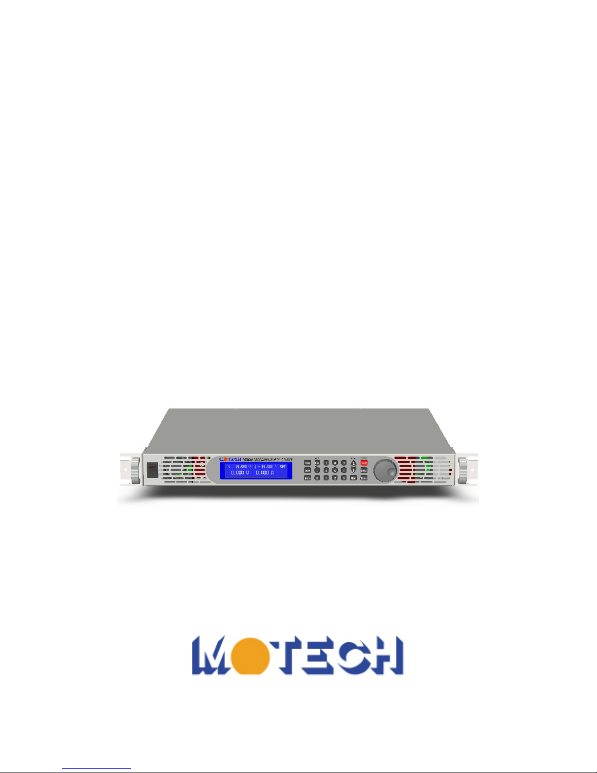
DS3640/DS6024/DS8018/DS10014
Programmable DC Power Supply
User’s Manual
Page 2

Legal Notices
The information in this document is subject to change without notice.
MOTECH makes no warranty of any kind with regard to this manual,
including, but not limited to, the implied warranties of merchantability
and fitness for a particular purpose. MOTECH shall not be held liable
for errors contained herein or direct, indirect, special, incidental or
consequential damages in connection with the furnishing, performance,
or use of this material.
MOTECH INDUSTRIES INC.
6F, NO. 248, SEC.3, PEI-SHEN RD., SHEN KENG HSIANG, TAIPEI HSIEN
222, TAIWAN, R.O.C.
Copyright Notices. Copyright 2008 MOTECH, all rights reserved.
Reproduction, adaptation, or translation of this document without prior
written permission is prohibited, except as allowed under the copyright
laws.
Page 3

Warranty
MOTECH persists in the faith of "reliable quality guarantees, and
forever thoughtful service", in one year since delivering the
products, we guarantee for free repairs on the troubles or damages
of the products caused while they are under normal operation.
MOTECH does not take a repair-free responsibility to any one of the following
situations; and we will charge to the respective repairs in accordance with the
maintaining situation:
(1) The product is not sold by MOTECH’s formally authorized agency
directly.
(2) Because the irresistible calamity changes or force majeure, which may
attribute to the user who has not followed the User Manual to operate or
caused by user’s fault, such as malfunction or damage made from
improper operation or others.
(3) User dismantles or repairs or repacks the product, or installs additional
accessories to it without MOTECH’s permission or authorization, which
cause the trouble or damage of the product(s).
Within guaranteeing service duration, user should be responsible and afford
respective expense to transport the trouble or damaged product to MOTECH or
the place which MOTECH specifies. And MOTECH will bear the expense in
delivering the fixed product back to user (Taiwan area only) or user-specified
place (Taiwan area only). User shall apply for the transporting insurance from
the insurance company alone.
MOTECH INDUSTRIES INC
6F, NO. 248, SEC.3, PEI-SHEN RD., SHEN KENG HSIANG, TAIPEI HSIEN
222,TAIWAN, R.O.C.
Customer Service Hotline: 886-2-2662-5093
Fax No.: 886-2-2662-5097
E-mail: [email protected]
Website:
http://www.motech.com.tw/
Page 4

Important Safe-Operation Guidelines
Properly Preserve This User Manual:
This Manual contains important
graphical & literal interpretations regarding installations, maintenance and
safety in operation, etc.
Qualified Professional Maintenance Personnel
As stated in this User Manual, neither spare parts nor exclusive fine
tuning is included inside this product; forbid user removing the outer
cover of a product while using it. For any double or unclear thing in
operation, please contact MOTECH or our agent’s professional service
personnel.
While removing the outer cover to repair by the professional person,
proper protection is still necessary to prevent people from getting an
electric shock.
Forbid repacking this product or its accessories; or it would cause danger
to user and make the warranty failure.
Precautions on Normal Operation
The recommended operation temperature of this product is 0- 40 degrees
C, relative humidity 20- 80. Do not boot this product when the ambient
temperature or humidity is beyond the one specified above, locating at a
place filled with volatilized explosive gas, flammable liquid materials.
Also, appropriately locate the cable that won’t stumble on passengers
walking along corridor or is exerted under external stress.
To protect personal safety and warranty rights of product, advise the user
to visually look over the integrality of the appearance of this product
before electrifying and starting this product. If parts become flexible,
strength sunken on outer casing, sharp angle or crack or under other
flawed or damaged state, contact MOTECH or its agent.
Avoid using the incomplete, damaged cable or cable not acquiring the
safety permission defined by related enactments. To renew the cable or
install additional extension cable, it should also select the cable material
meeting the specification of this product.
To operate this product, be sure that the protective earth connection of
power is already linked firmly. This precaution sustains for the other
Page 5

electrical equipment it collocates in operation to ensure personnel and
equipment's safety.
Suitable user of this equipment is one who can hold basic electrical idea
and comprehend this User Manual in details.
The power cable attached to this product meets with the related safety
regulations and can secure operating safety under correct use. To pull
power plug out of receptacle, user should hold the plug and pull it out.
Directly pulling power cable would result in danger. At the instance of
turning off power switch the residual electric charges in electric
capacitors still might cause electrical shock to user. We recommend user
to wait for five minute till the inner fan ceases, which means that the
discharge process it finished.
Before carrying on general maintenance and safeguarding, please
shut off power supplied to this product, pull out the plug and
cutting off the joined load. Use dry cloth to whisk or wipe off outer
cover and cable; for safety concern, avoid using suds or organic
solvent to clean this product.
Page 6

Store/Move/Maintain/Handle
Storage
When
this
device is not in use, properly package it and store it on environment
suitable for storage (if in a good preserving environment, the packaging process
can be waived).
Freight
While moving this product, move it by using the original wrappings to
pack this product in advance. If the wrapping material is lost, use an
equivalent buffer material to replace it in packaging; and with external
marks indicating “fragile & water-prevention”.
This product is sort of precise device; please try one's best to use
qualified means of transport to transport it. And t
ry one's best to avoid
dropping or others that would jeopardize this product.
Maintenance
This
product
is free from any maintainable item for user normal user to
maintain about. (except the one indicated in this Manual). When any abnormal
condition happens to this product under user’s judgment, please contact us or
our agent immediately. Never try to maintain this product by oneself that would
cause unnecessary danger in consequence and which might cause even severe
damage to this product.
Disposal
When the device in badly condition and can’t be used or repaired, please
discard it according to your company disposal procedures or local legal
procedures. Don’t discard arbitrary to avoid polluting environment.
Page 7

Index
1.
Preface ................................................................................................. 1
1.1
Products Outline ............................................................................ 1
1.2
Features ......................................................................................... 2
2.
Specification ........................................................................................ 4
3.
Cautions Before Using ........................................................................ 9
3.1
Check and Confirm Accessories before Using ................................ 9
3.2
Operation Instructions .................................................................... 9
3.3
Ambient Environment .................................................................... 9
3.4
Storage .........................................................................................10
3.5
Power-line voltage ........................................................................10
3.6
Fuses ............................................................................................10
3.7
Preheating Time ............................................................................ 11
3.8
End test ........................................................................................ 11
3.9
Cautions in Operation ................................................................... 11
4.
Panel Demonstration..........................................................................12
4.1
DS3640/DS6024/DS8018/DS10014 Panel ....................................12
4.1.1Front Panel ..............................................................................12
4.1.2Rear Panel ...............................................................................30
5.
Operation Interpretation ...................................................................34
5.1
Voltage Setting..............................................................................34
5.2
Current Setting .............................................................................34
5.3
Over-voltage Protection OVP........................................................34
5.4
Over-current Protection OCP ........................................................34
5.5
Voltage Output ..............................................................................35
5.6
Voltage Output Controlled by Knob controller ..............................35
Page 8

5.7
Timer Function .............................................................................35
5.8
Make Series (Cascade)/Parallel Setting .........................................36
5.8.1Parallel Connection Setting ......................................................36
5.8.2Cascade Setting .......................................................................38
5.8.3Error Message of Series/Parallel Connection ............................41
5.9
External Tuning Setting ................................................................42
5.10Timer of Current Flow ..................................................................43
5.11Programmable Capability (SCPI Command Only) ........................45
5.12Series Connection Function (RS485).............................................51
5.12.1Series Connection Command List ............................................51
5.12.2 Error Response List ................................................................54
6.
Protections and Error Messages ........................................................55
6.1
Over-voltage Protection (OVP) .....................................................55
6.2
Over-current Protection (OCP) ......................................................55
6.3
Overpower Protection (OPP).........................................................55
6.4
Constant Voltage Protection (CV TO CC) .....................................56
6.5
Constant Current Protection (CC TO CV) .....................................56
6.6
Over-temperature Protection (OTP) ..............................................56
6.7
Low Voltage Protection (ACD) .....................................................57
6.8
Error Input Message .....................................................................57
7.
Remote Interface communication protocol .......................................58
7.1
Prefaces ........................................................................................58
7.2
Parameters Definition ...................................................................58
7.3
The Error/Event List .....................................................................59
7.4
Compatible Protocol of MOTECH LPS & PPS Product Family.....60
7.5
SCPI Conformable Information.....................................................63
7.5.1Common SCPI commands .......................................................63
7.5.2SCPI Command subsystem ......................................................64
Page 9

7.6
State Bit Definition .......................................................................75
7.7
LAN Communction ......................................................................75
7.7.1Using Web Server ....................................................................76
7.7.1.1Main Page (Home) ..................................................................76
7.7.1.2Setting Page (Configuration)....................................................77
7.7.1.3Status of Page (Status) .............................................................77
7.7.1.4Web Control ............................................................................78
7.7.2Using Telnet ............................................................................78
7.7.3Using Sockets ..........................................................................79
8.
Assemble Accessories .........................................................................80
8.1
Assemble Rack Mount Brackets....................................................80
8.2
Assembly of Output Protective Shield (DS6024/DS8018/DS10014)
.....................................................................................................80
8.3
Assembly of Remote Sense Protective Shield
(DS6024/DS8018/DS10014) .........................................................80
9.
Accessories .........................................................................................82
Page 10

1
1. Preface
1.1 Products Outline
MOTECH DS3640/DS6024/DS8018/DS10014 is a programmable DC
power supply with single output that offers the maximum power output up to
1440 watts (0 ~ 36V/40A or 0 ~ 60V/24A or 0 ~ 80V/18A or 0 ~
100V/14.4A). With a 16-bit D/A, A/D converter embedded, DS3640/
DS6024/DS8018/DS10014 comes with the resolution of 1mV in voltage
setting and 1mA in current setting. With the cascaded (series) or parallel
connections of up to four (4) devices of DS3640/DS6024/DS8018/DS10014,
it may be able to provide a maximum power output up to 5760 watts. When
four (4) DS10014 are cascade connected, the maximum output voltage can
reach up to 400V. When four (4) DS3640 are put in parallel connections, the
output current can reach up to 160A. The feature of series/parallel
connections makes DS3640/DS6024/DS8018/DS10014 more convenient
and flexible for varies applications.
DS3640/DS6024/DS8018/DS10014 has provided a knob controller,
numerical and function keys for users to manipulate this electronic
instrument more easily and fast. Also, DS3640/DS6024/DS8018/DS10014
provides a memory space for user to store 10 settings that can be recalled
directly. This feature offers an easy way to restore the application setting. In
addition, users can use a program to control when to cut off the output. This
feature provides an extra safety for burn in room and electroplating
applications. DS3640/DS6024/DS8018/DS10014 also provides over voltage
protection (OVP), over current protection (OCP), and over power protection
(OPP) features used to keep the output voltage and current within the safety
level preventing the target from the damage caused by the over current. The
key lock feature is added to avoid accidentally wrong setting to the
DS3640/DS6024/DS8018/DS10014. When the input power and the load
change, the DS3640/DS6024/DS8018/DS10014 provides a stable output
with the load and line regulation within 0.05% and the transient time less
than 1 ms to maintain a very steady output. When in remote mode, DS3640/
DS6024/DS8018/DS10014 may output a new setting in 50 ms after receive a
command. This quick response time may increase the throughput on the
mass production lines.
Page 11

2
1.2 Features
1) Output Voltage & Current
Voltage output range: 0 ~ 36V (DS3640) / 0 ~ 60V (DS6024)
0 ~ 80V (DS8018) / 0 ~ 100V (DS10014)
Current output range: 0 ~ 40A (DS3640) / 0 ~ 24A (DS6024)
0 ~ 18A (DS8018) / 0 ~ 14.4A (DS10014)
Power output range: 0 ~ 1440W
2) Digital knob controller, numerical keys and functions keys
The knob controller can be used to rapidly change the output voltage
setting and simulate the surge of the voltage output. It successfully offers a
good solution to the tests of triggering circuit. Numerical keys facilitate
users making fast setting without withstanding the conventional VR analog
simulation. Using function keys to switch modes makes the overall
operation more humanizing and easy to deal with.
3) Precise voltage and current measurement
Besides the precise output, DS3640/DS6024/DS8018/DS10014 also offers
the capacity of voltage & current measurement (read back) accurately that
users may be able to save extra expense and space for extra measuring
instruments.
4) Memory device and timer function
DS3640/DS6024/DS8018/DS10014 provides a memory space for users to
save 10 settings. This feature makes users no need to hold and memorize
too many settings in mind. They simply need to store the settings in
DS3640/DS6024/DS8018/DS10014 hardware and restore the setting at any
time. The DS3640/DS6024/DS8018/DS10014 has one (1) timer with the
resolution of 1 second. The timers are used to time the outputs. When the
timer counts down to zero the DS3640/DS6024/DS8018/DS10014 will
automatically turn the output off. This feature is useful when the
DS3640/DS6024/DS8018/DS10014 is providing power to the test object in
a burn-in room. The programmable capability allow this equipment to run
at a burn-in room that operator needs not to care about time setting points
because this equipment will shut off output when the specific set time
points reaches. It has covered the advantages of both safety and flexibility.
DS3640/DS6024/DS8018/DS10014 will perform perfect control of time
Page 12

3
and current resolution as entirely meeting customer's demanding.
5) OVP (over voltage protection), OCP (over current protection) and OPP
(over power protection) and key lock functions
The over voltage protection (OVP), over current protection (OCP) and over
power protection (OPP) features limit the maximum output current and
voltage to avoid damages to the test objectives when doing
experimentations in a laboratory. The key lock feature disables all keys
except the CLR key. It prevents DS3640/DS6024/DS8018/DS10014 from
the accidentally wrong setting and then avoids the damages to the target.
6) Series & parallel connection mode
The series-parallel connection mode of two or more units (maximum to 4
units) largely increases product’s power-supplying capability. Under the
parallel connection mode of four DS3640 the maximum output is
36V/160A; and under the cascaded connection mode of four DS10014, the
maximum output is 400V/14.4A. Power supplied under these two modes
reach up to 5760 watts output that can meet most electric experiments’
demands.
7) Multi-units series connection mode
Computer can connect to system through USB interface. RS485 interface
can be used to connect 31 units at most. It can save GPIB interface card and
GPIB wiring expense and simplify the connection control.
Page 13
4
2. Specification
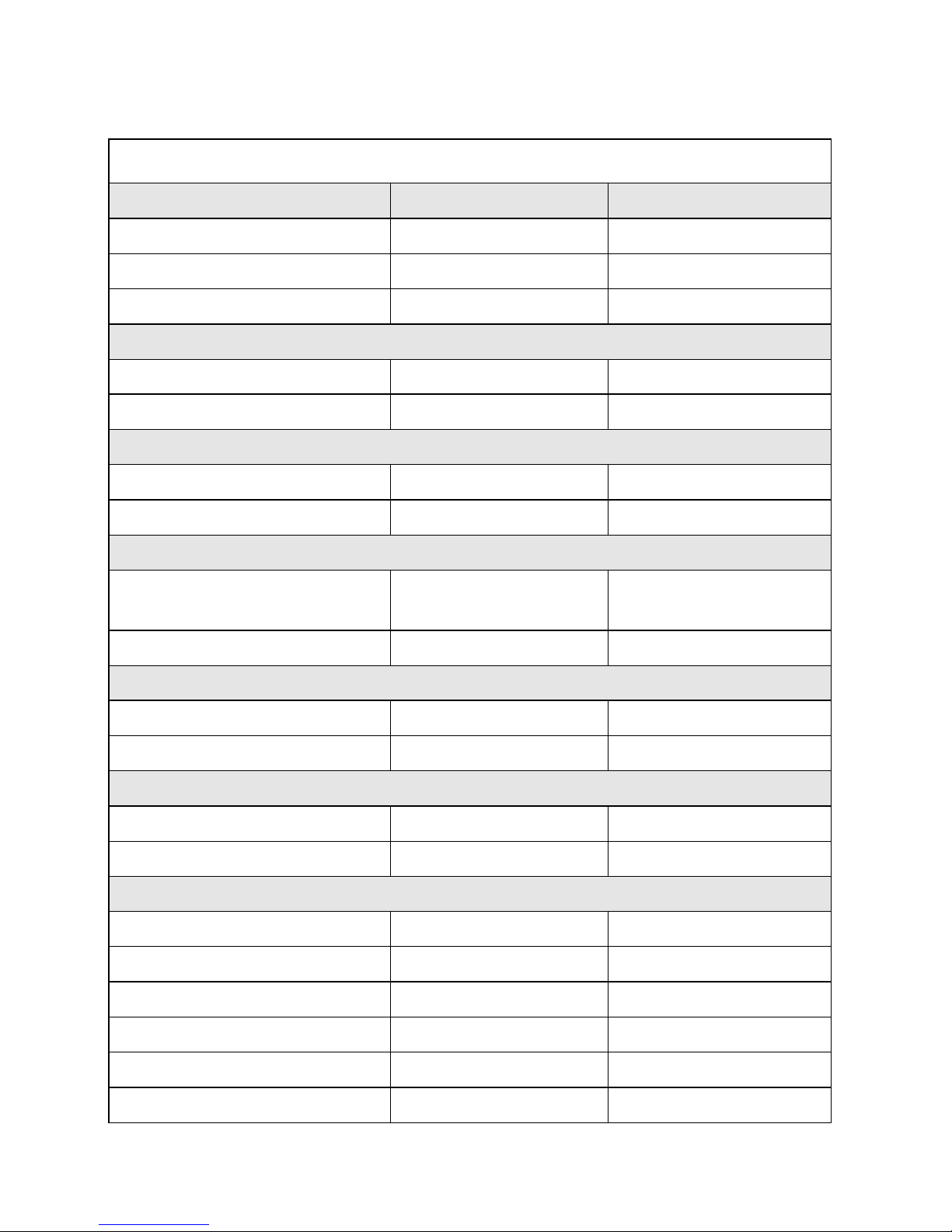
DS3640/DS6024 Specifications
Output Rate
DS3640 DS6024
Output Voltage 0~36V 0~60V
Output Current 0~40A 0~24A
Output Power 1440W 1440W
Line Regulation
Voltage
4mV 6mV
Current
4mA 4mA
Load Regulation
Voltage
8mV 8mV
Current
8mA 7mA
Ripple and Noise (20Hz-20MHz)
Normal Mode Voltage
5mVrms/60mVpp
(Load 0.5%)
6mVrms/70mVpp
(Load 0.5%)
Normal Mode Current 90mA 70mA
Resolution
Programming 1mV/1mA 1.5mV/1mA
Readback 1mV/1mA 1.5mV/1mA
Programming Accuracy ( % output+offset)
Voltage 0.05%+10mV 0.05%+15mV
Current 0.05%+10mA 0.05%+8mA
Readback Accuracy ( % output+offset)
Voltage 0.05%+10mV 0.05%+15mV
Current 0.05%+10mA 0.05%+8mA
Transient Response Time
1mS 1mS
Efficiency 80% 80%
OVP Adjustment Range 2~38V 3~64V
OVP Accuracy 200mV 300mV
Page 14
5
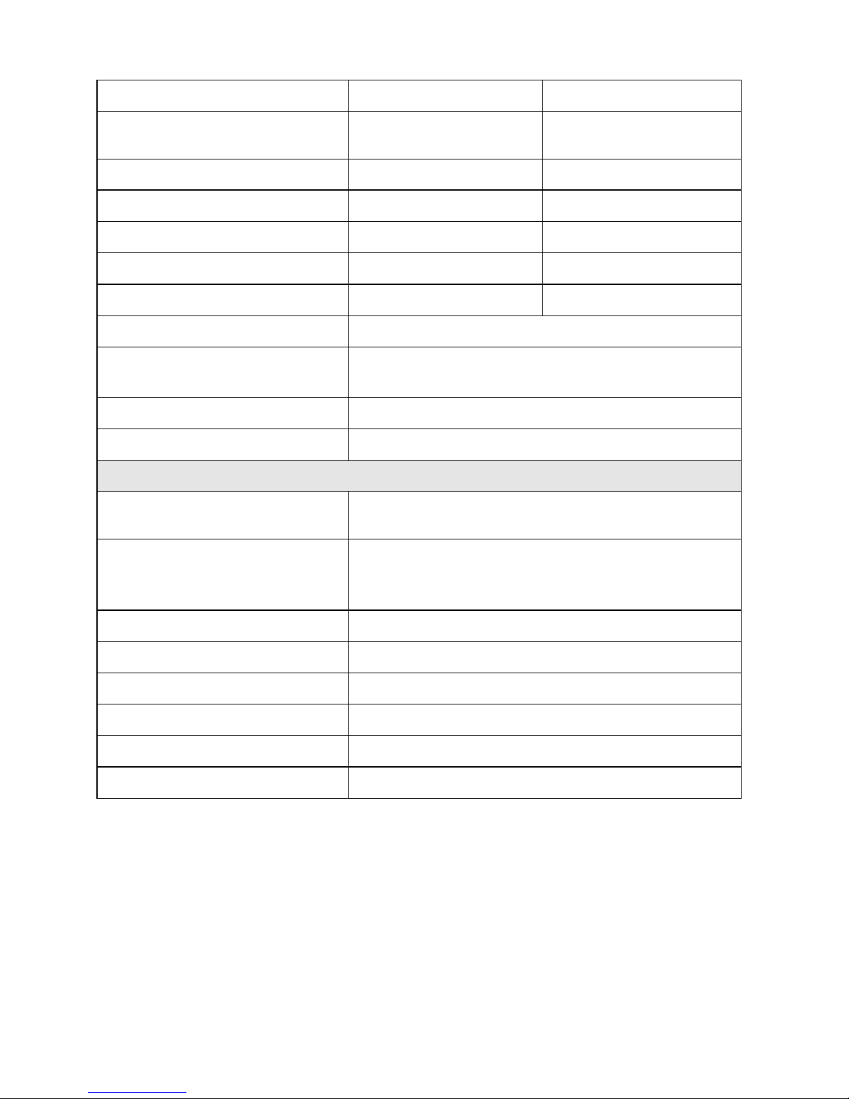
Command Response Time 50mS 50mS
Power Factor
0.99
(Full load)
0.99
(Full load)
Remote Sense Compensation
2V 2V
Rising Time at Full Load
15mS 20mS
Rising Time at No Load
15mS 20mS
Falling Time at Full Load
15mS 20mS
Falling Time at No Load
1000mS 1000mS
Standard Interface USB
Standard Accessories
Power CordTerminal Block for Rapid Plug
Connector
Optional Interface LAN, GPIB
Optional Accessory RS-485 Cable
General
AC Line Rated Input Voltage
100~240VAC
(Full load)
Tolerance/Variation in
Voltage
-
15%
~ +10%
(10% power de-rating mode
when voltage under 95 Vac)
Rated Frequency 47Hz~63Hz
Maximum Rated Input Power
1700VA
Temperature Ratings(O) Operation (0 °C ~ 40 °C)
Temperature Ratings(S) Storage (-10 °C ~ 70 °C)
Dimensions(W*H*D) 420*43.6*432mm
Weight 9kg
Page 15
6
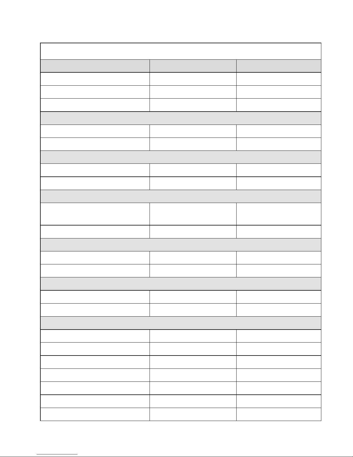
DS8018/DS10014 Specifications
Output Rate
DS8018 DS10014
Output Voltage
080V 0100V
Output Current
018A 014.4A
Output Power 1440W 1440W
Line Regulation
Voltage
8mV 10mV
Current
4mA 4mA
Load Regulation
Voltage
10mV 12mV
Current
6.5mA 6mA
Ripple and Noise (20Hz-20MHz)
Normal Mode Voltage
7mVrms/80mVpp
( Load 0.5% )
8mVrms/80mVpp
( Load 0.5% )
Normal Mode Current
50mA 40mA
Resolution
Programming 2mV/1mA 2.5mV/1mA
Readback 2mV/1mA 2.5mV/1mA
Programming Accuracy ( % output+offset)
Voltage 0.05%+20mV 0.05%+25mV
Current 0.05%+7mA 0.05%+6mA
Readback Accuracy ( % output+offset)
Voltage 0.05%+20mV 0.05%+25mV
Current 0.05%+7mA 0.05%+6mA
Transient Response Time
1mS 1mS
Efficiency
80% 80%
OVP Adjustment Range
485V 5105V
OVP Accuracy 400mV 500mV
Commond Response Time 50mS 50mS
Page 16
7
Power Factor
0.99
(Full load)
0.99
(Full load)
Remote Sense Compensation
2V 2V
Rising Time at Full Load
25mS 30mS
Rising Time at No Load
25mS 30mS
Falling Time at Full Load
25mS 30mS
Falling Time at No Load
1000mS 1000mS
Standard Interface USB
Standard Accessories
Power CordTerminal Block for Rapid Plug
Connector
Optional Interface LAN, GPIB
Optional Accessory RS-485 Cable
General
AC Line Rated Input Voltage
100240VAC
( Full load )
Tolerance/Variation in Voltage
-15%+10%
( 10% power de-rating mode
when voltage under 95 Vac )
Rated Frequency
47Hz63Hz
Maximum Rated Input Power 1700VA
Temperature Ratings(O)
Operation(040)
Temperature Ratings(S)
Storage (-1070)
Dimensions(W*H*D) 420*43.6*432 mm
Weight 9kg
Features of DS3640/DS6024/DS8018/DS10014:
Graphical LCD easy to read
Compact, high efficiency and high power density
40A output connector for fast connecting
Numerical & function keys for friendly setting
Store and recall settings (up to 10 sets)
Timer (1 sec ~ 100 hours)
Page 17

8
Programmable (SCPI command only), with up to 10 sets of program and
maximum 150 steps in total
Extra 5V/1A output, suitable for fixture circuit without the need of
additional power
Precise voltage and current measurement
OVP, OCP and key-lock function
Series & parallel connection modes are applicable
Series connection mode. Max. is up to 31 units (using RS485 interface)
Mean measuring time per measurement is 50mSec
Standard USB interface
Optional interfaces:GPIB, LAN
Page 18

9
3. Cautions Before Using
3.1 Check and Confirm Accessories before Using
As to safeguard your rights, after receiving this product, please confirm the
items received in accordance with the ones listed below:
1.
The appearance of the products is without scratch or other damages.
2.
Standard parts as shown in Attachment 1 (Parts List) of Chapter 9.
If there is any situation as stipulated above found, please inform us as
soon as possible and we would correct it for you immediately.
3.2 Operation Instructions
This PRODUCT is a precise instrument. In order to prevent it from improper
operation causing the damage, be sure to read and comprehend this User
Manual. And in order to maintain accuracy, send it to perform factory's
calibration once per year.
3.3 Ambient Environment
1.
Do not locate or operate this product in an environment with dust,
vibration, or corrosive gas and do not explore this product directly to
the sunlight. Operate it in an environment with temperature 0~40oC
& relative humidity 20%~80%. Pause the operation when ambient
temperature is over 40oC; undo the operation only after the ambient
temperatures drops to the acceptable temperature range. Operating
temperature over the above range would damage the host part.
2.
This product is equipped with one blow-out type cooling fan on the
back board and three suck-in cooling fans on inner side of front
board. Note on good ventilation near the cooling fans and keep the
boards with a space above 10cm away from wall. To maintain a good
accuracy operation, do not block the ventilation holes spaces.
3. Although this product is designed to well-block the noise from
the AC power source, still, try one’s best to operate it in a
background environment with low power noise and ensure that
the system earth is made substantially. If the power noise is
unavoidable, please install a power filter.
Page 19

10
3.4 Storage
The storage temperature range of this product is within -10ºC ~ 70ºC and
R.H. should be within 80% without moisture condensing. If not operating
this product for a long time interval, pack it with original packaging or
similar one and put it in a dry place without hit by direct sunlight.
3.5 Power-line voltage
Rated AC power source connected to this product is within 100V~240V
(refer to the Product Specification for details). Before connecting to external
power source, be sure that the power switch is in OFF state and look over
the suitability of power cable (including the extension line) being as
compatible to the rated voltage/current and sufficient circuit capacity and
then, connect the cable tight.
Warning:
The power cable attached with this product is safety
certified for this product operating in rated range. To
change a cable or add a extension cable, be sure that it
can meet the rated range of this product; any misuse of
additional cable would jeopardize user’s rights and
interests of warranty service.
3.6 Fuses
This product is a switching mode power supply. The fuse installed inside is a
multi-barrier protection design of hardware. It is hardly be breakdown under
normal operation status. In case the fuse is melted to break, it shows another
malfunction exists that causes the fuse to break. In such case, it is suggested
to send this product back for services.
Warning:
To sustain user’s rights of warranty service and avoid
misconnection that would cause jeopardy from it, we
don’t recommend user to dismantle the casing and
change fuse by oneself.
Page 20

11
3.7 Preheating Time
All movements of this product will activate at the same time when the power
is on. However, to reach the specified equipment accuracy, please preheat it
for at least 30 minutes.
3.8 End test
When testing is over and not to be restarted for a while, or when this product
isn’t under use, or user needs to leave during operation, be sure to turn the
power switch on the panel to OFF position as to turn off the power. After
power switch is turned to OFF position, the inner fans will still run for a few
seconds to carry on the inside electric capacitor discharge process per safety
code requirement. Once the discharge process is complete, this product will
make automatic shut-down in response.
3.9 Cautions in Operation
A. While under cascaded connection mode, each DS3640/DS6024/DS8018/
DS10014 shall be in power-on state and output shall be "ON". In case
there is any one DS3640/DS6024/DS8018/DS10014 is in power-off state
or output is "OFF", the associated output current will flow over the
output bypass diode of the power-off unit and burn it out.
B. While under parallel connection mode, the output voltage of each
DS3640/DS6024/DS8018/DS10014 shall be set to equal. If the setting
value of each unit is not the same, the higher output voltage will feed
back to the smaller unit and destroy its inner parts.
C. When the AC input voltage is lower than the full-load voltage which is
100 Vac, DS3640/DS6024/DS8018/DS10014 will activate an inner
overtemperature protector and cut off the output in response. To ensure
that the entire test process can be complete smoothly, confirm that the
input AC voltage is within the specified range.
Page 21
12
4. Panel Demonstration
4.1 DS3640/DS6024/DS8018/DS10014 Panel
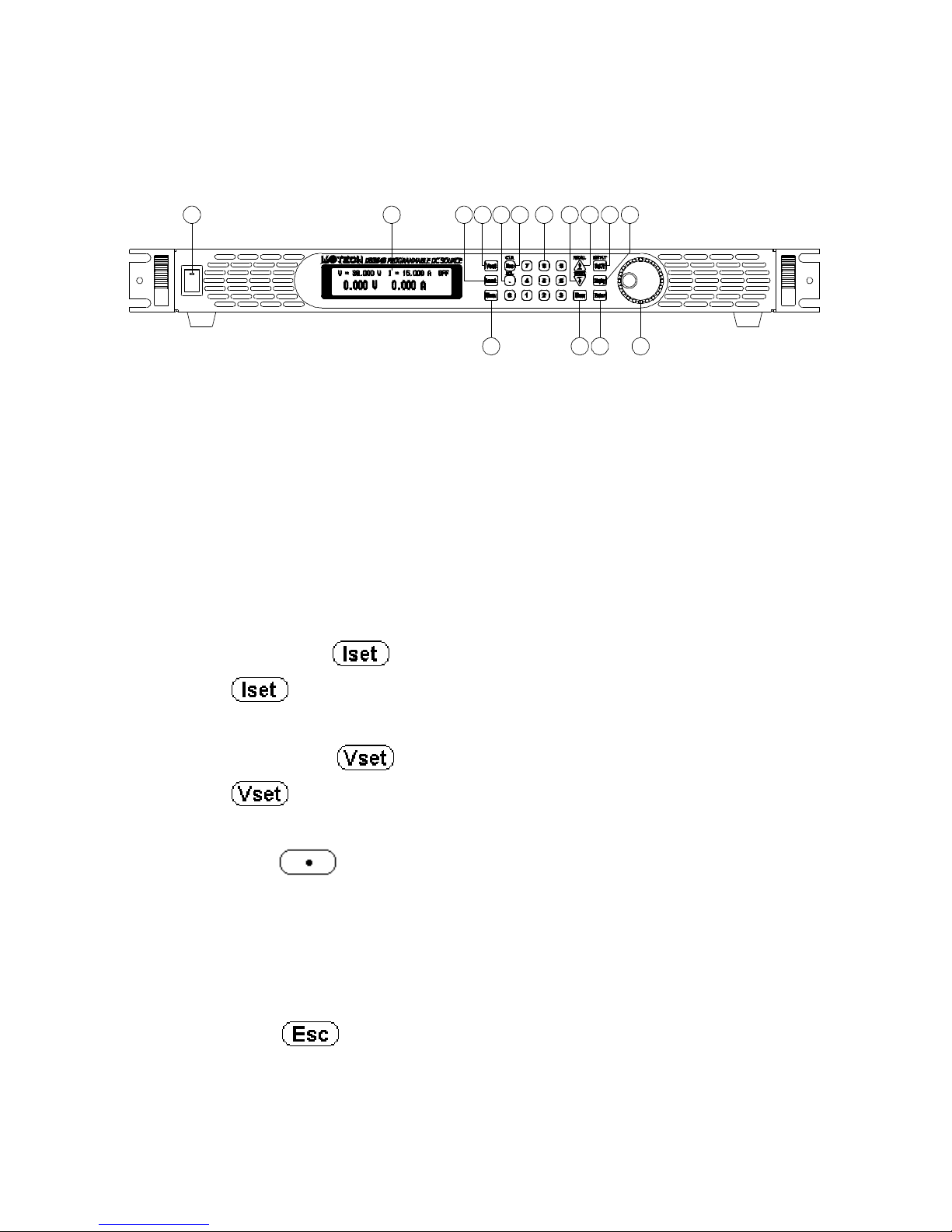
1
15
2 3 4 5
1214 13
109 1176 8
4.1.1 Front Panel
(1) Power switch:
Please consult the “Cautions before use” before turnning on power
switch.
(2) Display:
192*32 Graphic LCD Module
(3) Current setting :
Press
to set up the current limit.
(4) Voltage setting :
Press to set up the output voltage.
(5) Dot/Local :
This button is applied as a decimal point. Or push this button after
entering REMOTE online state to resume into LOCAL mode
(unit-operation mode). Or press this button to release after entering
LOCK page.
(6) ESC/CLR
:
Press this button to clean up numerical setting or jump to the previous
page.
Page 22
13
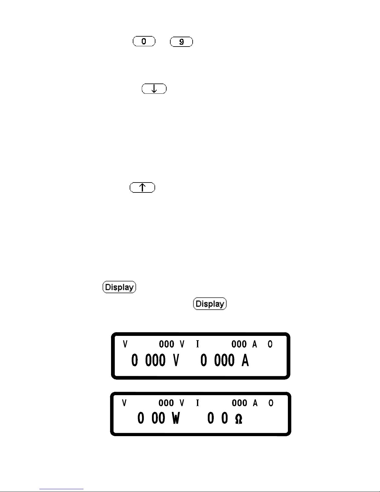
(7) Numerical keys ~ :
They are used to fast input the voltage or current value or choose the
setting option in Menu page.
(8) Down/Right/Store :
This key is a compound key for the following three functions:
Down: In “Menu Se
tting” status, use this “Down” key to move cursor
to the next item.
Right: Under “Output” status, use this key to move cursor right.
Store:
Under Memory Setting status, use this key to store setting to
the selected memory set.
(9) Up/Left/Recall :
This key is a compound key for the following three functions:
Up:
In “Menu Setting” status, use this “Down” key to move cursor
to the up item.
Left: Under “Output” status, use this key to move cursor left.
Recall: Under Memory Setting status, use this key to re
call setting
from the selected memory set.
(10) Display :
In “Menu Setting” page, press to return to main page or
switch the display to show the power and the loading resistance
=
36
. FF
5
1
.
= .
.
.
1= .
5
FF
.
3=6
.
Page 23
14
(11) Output :
Control the On/Off of the output power.
(12) The knob controller:
Use this tuner to adjust voltage or current (press first to let
cursor display first). It is an option item in Menu Setting.
(13) Enter :
This key is the confirming key of current or voltage setting value; or
press under output status to dynamically adjust voltage (at CV
mode) or current (at CC mode).
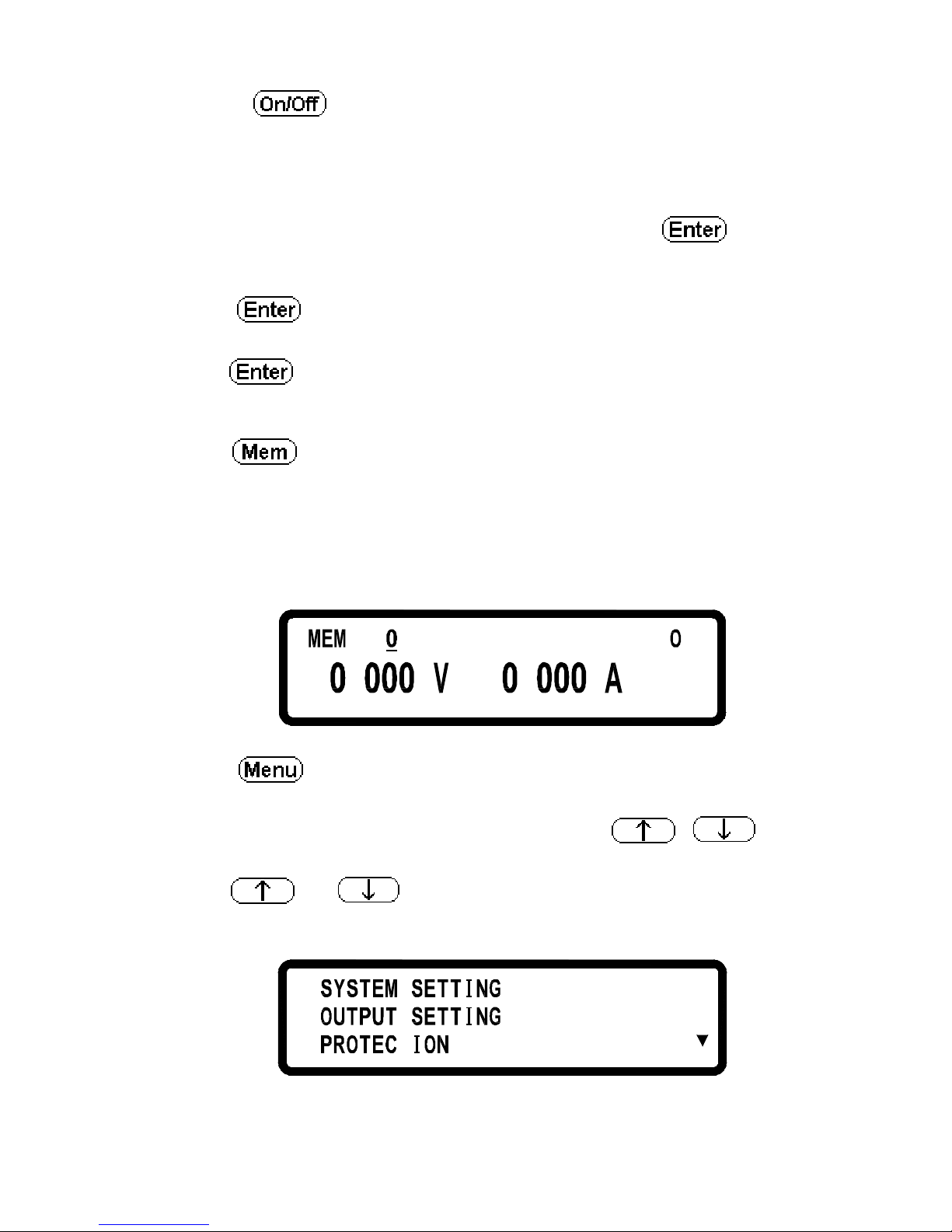
(14) Mem :
Press this key to enter the memory device status page. Users can then use
the numerical key or knob to select the target memory set to save or
recall the configuration by pressing the STORE or RECALL key. Ten
sets are available in selection.
= FF
. .
(15) Menu :
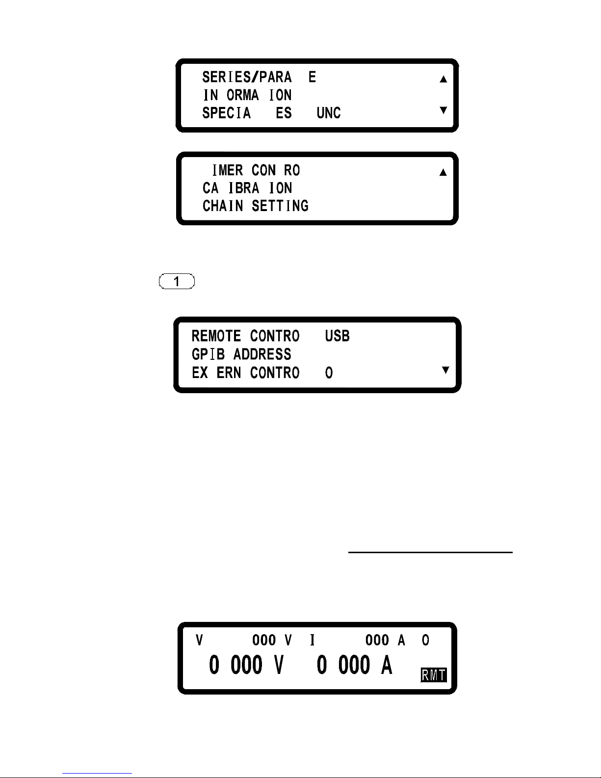
Use this key to make system parameters setting. There are eight (8)
major items under operation. Users may press
,
,
and the
numerical keys to enter the corresponded setting page.
Press
or key to jump to one of the following three
pages:
.
1
23.
.
T
Page 24
15
.4
56..F
LL L
T
L T T F
T
.7 T
89. L
.
LT
1. SYSTEM SETTING:
Pressing key in the first page of Menu Setting can enter the
following “SYSTEM SETTING” page.
L=
= 1
T =L FF
REMOTE CONTROL:
Choose the transmission interface
(USB/GPIB/ETHERNET)
*USB interface is a virtual COM port, baud rate is 57600bps
Data bit :8
Parity check :none
Stop bit :1
Please download USB Driver on http://www.motech.com.tw
.
*If entering the Remote mode, screen will present RMT symbol as shown
in the following picture.
1
.
= .
5
FF
3
.
= .
6
Page 25
16
GPIB ADDRESS:
Set up GPIB ADDRESS (1~31)
EXTERN CONTROL:
Set up the external
control to voltage
control (VOLT 0~10V or 0~5V),
resistance
control (RES 0~5K) or off (OFF).
=
5F52=
= F
552. 552. 552.
F
L
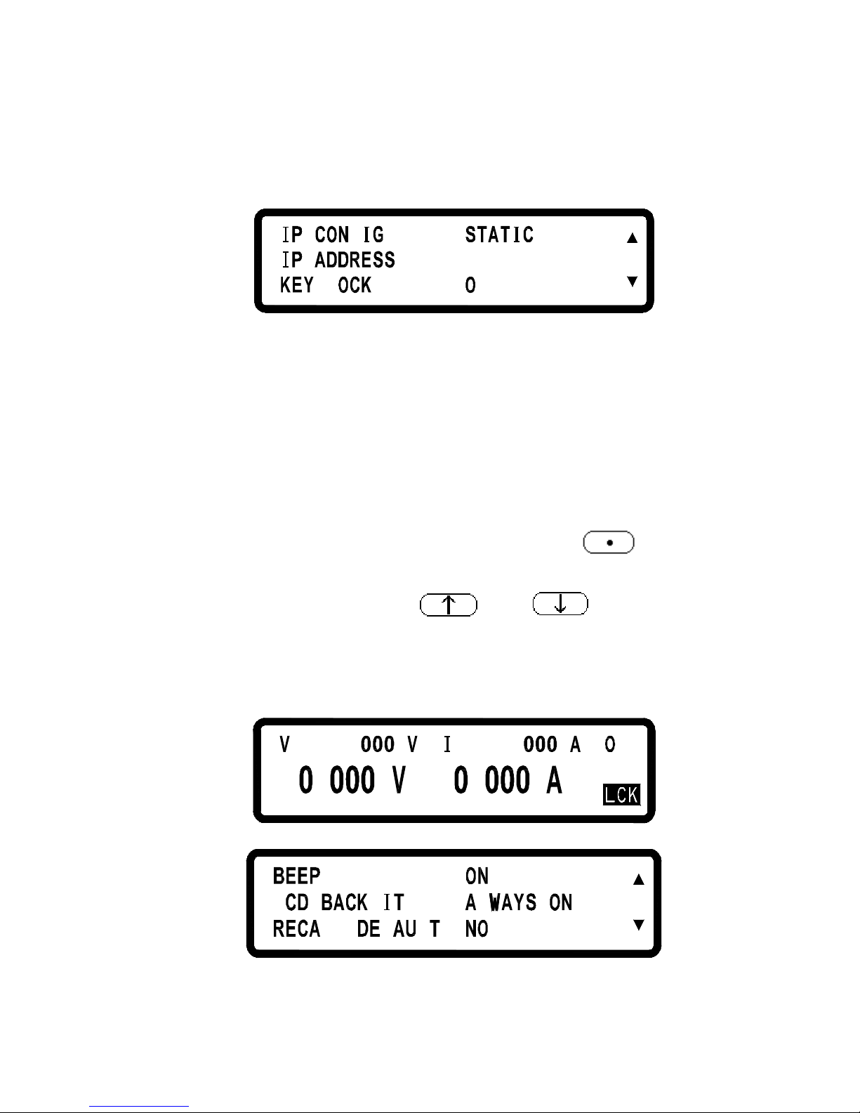
IP CONFIG:
STATIC :users input IP address
DHCP : IP address is assigned by the server.
IP ADDRESS:
If IP CONFIG is set to STATIC, users shall enter
the IP addresses here.
If IP CONFIG is set to DHCP, the assigned
IP
address will be shown here.
KEY LOCK:
While exit the setting page after en
able KEY
LOCK, all keys except the
key that can
disable KEY LOCK status will be deactivated.
*Simultanously presses both and keys in the main
page can also unlock keys.
*While
entering
KEY LOCK state, screen will present LCK symbol as
shown in the following picture.
6 .= 3
.
5 .= 1
.
FF
L
=
F L
L=
=
L
L
L
BEEP:
Turn the Buzzer ON/OFF
Page 26
17
LCD BACKLIT:
Set the backlight of the LCD
to always
ON or OFF after 1/5/10/30 minutes
RECALL DEFAULT:
Restore the manufactuer default setting
5
= .
= FF
F
=
,
=
.
F
=
,
FF
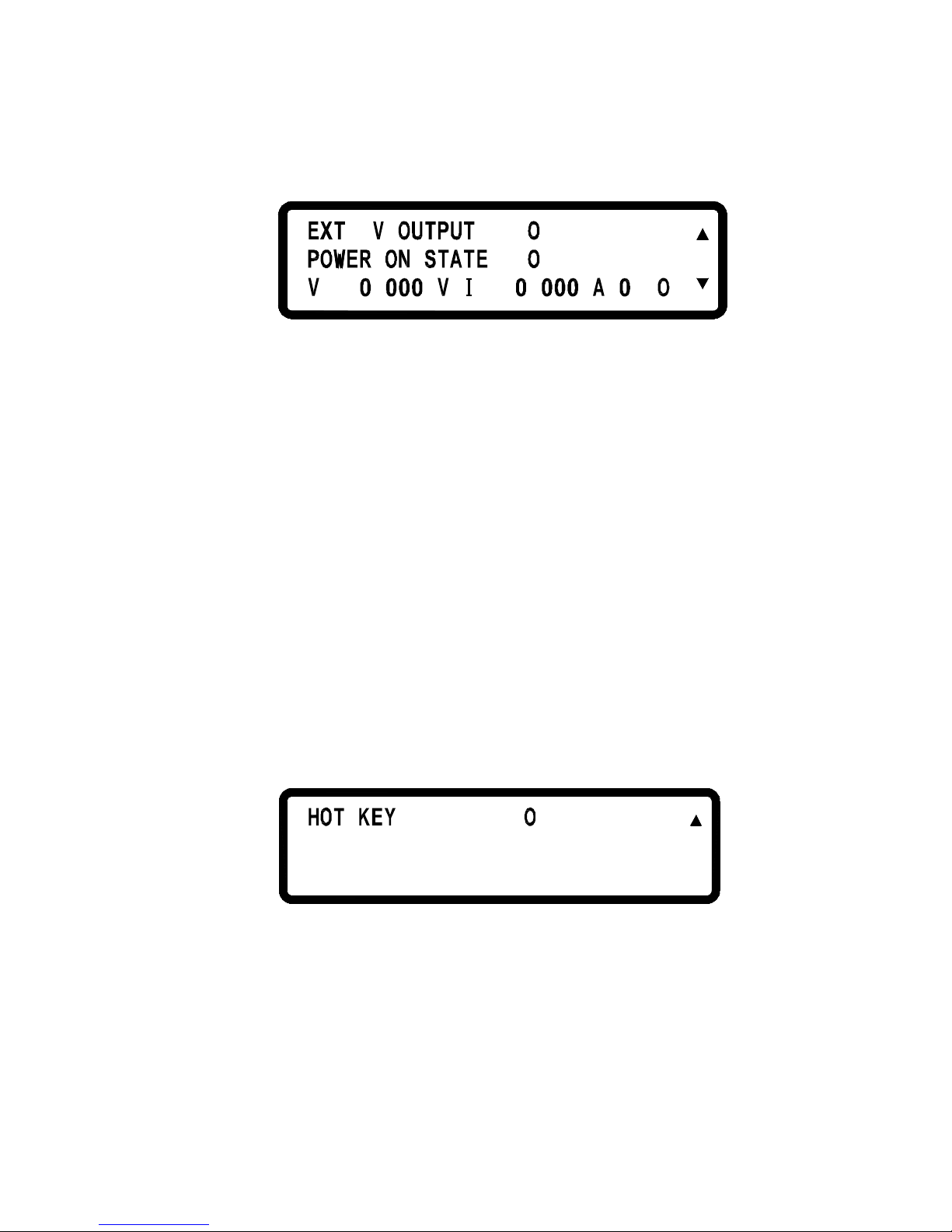
Ext 5V OUTPUT:
Turn the extra 5V power (on the rear panel)
ON/OFF
POWER ON STATE:
Users may be able to set the output
state after
the power is on. Wh
en OFF is selected,
DS3640/DS6024/DS8018/DS10014
will do
nothing after power on.
If LAST is selected,
then after power on, DS3640/DS6024/
DS8018/DS10014
will be set to the last
output state when power off. If USER
(user
defined)
is selected, it will jump to next line
to make setting of output voltage, current
,
and output state.
Then after power on,
DS3640/DS6024/DS8018/DS10014
will set
up the output to ON/OFF and the output
voltage and
current according the settings
here.
= FF
HOT KEY:
Set the HOT KEY functioin ON/OFF, if the
HOT KEY function is ON, User can using
0 –
9 number keys to recall the voltage and
current setting value in the memory that have
been saved.
*If entering the HOT KEY mode, screen will present RMT symbol as
shown in the following picture.
Page 27
18
6 .= 3
.
4 .=
.
FF
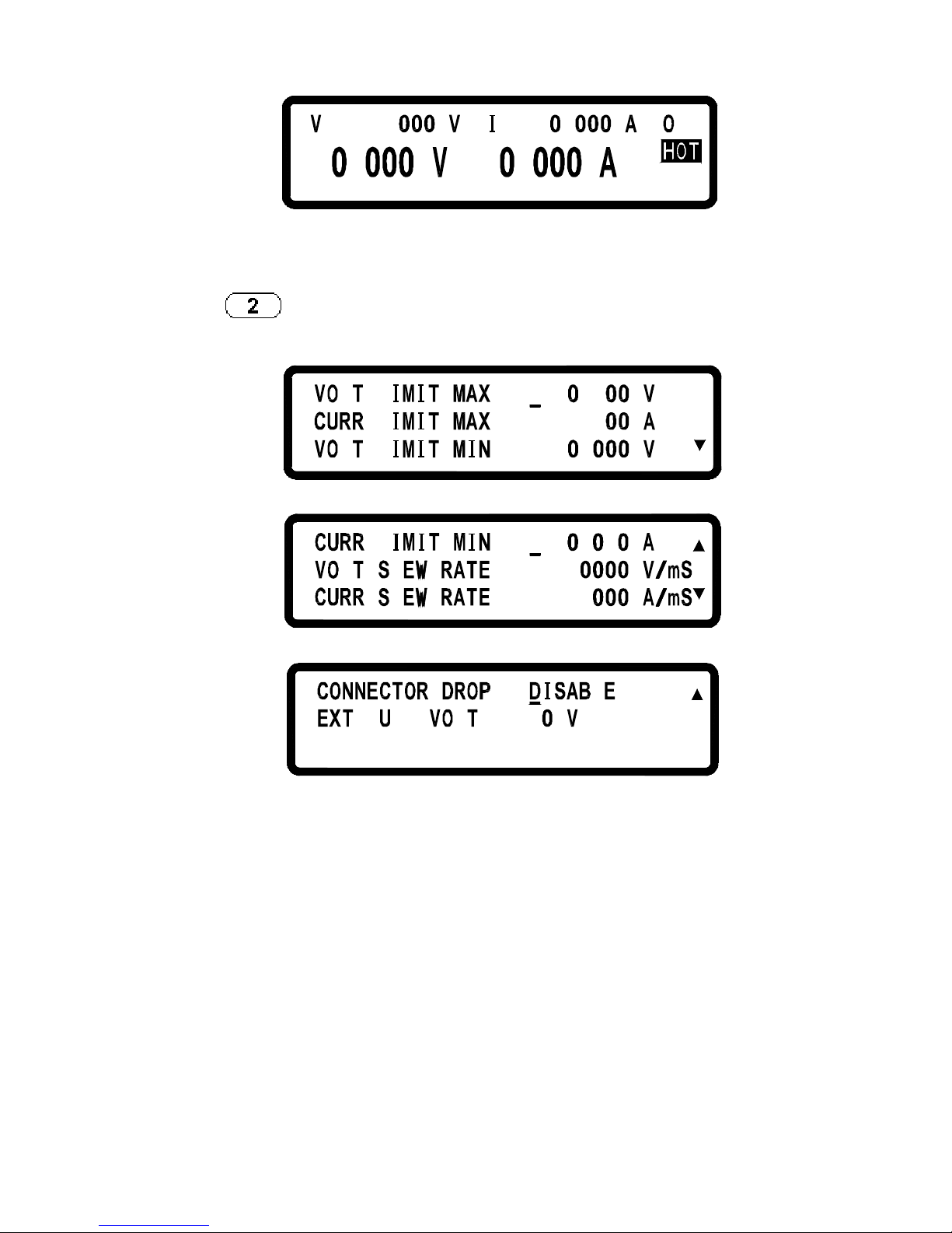
2. OUTPUT SETTING:
Press in the first page of Menu Setting to enter OUTPUT
SETTING page.
LL
LLL
= .6 5
=
=
5
.
24
.
L
L L
L
.= 1
=
=
.
3
.1 2
F LL
= L
L = 1
VOLT LIMIT:
Limit of the output voltage setting
CURR LIMIT:
Limit of the output current setting
VOLT SLEW RATE:
Voltage ascending/descending slope
(3640:0.01 ~ 2.4V/mS)
(6024:0.01 ~ 3V/mS)
(8018:0.01 ~ 3.2V/mS)
(10014:0.01 ~ 3.3V/mS)
CURR SLEW RATE:
Current ascending/descending slope
(3640:0.01 ~ 2.5A/mS)
Page 28
19
(6024:0.01 ~ 1.2A/mS)
(8018:0.01 ~ 0.72A/mS)
(10014:0.01 ~ 0.48A/mS)
CONNECTOR DROP
Turn on/off the connector drop calibration
function
EXT FULL VOLT:
External tuning setting with full-scale
voltage (10V / 5V)
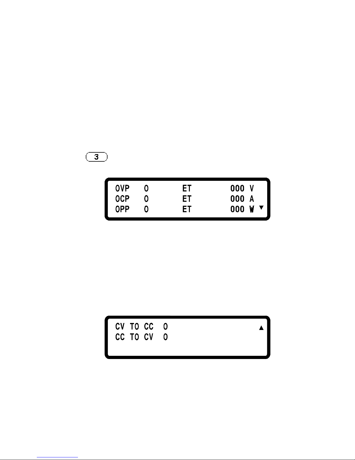
3. PROTECTION SETTING (PROTECTION)
Press
key in the first page of Menu Setting to enter
PROTECTION page.
F
F
8
.
3
=
S
S
S
=
=
0
24
41 4
.
.
F
F
FF
=
=
=
OVP:turn on/off the
overvoltage protection
SET: set up the overvoltage
protecting point.
OCP:turn on/off the
overcurrent protection
SET: set up the overcurrent
protecting point.
OPP:turn on/off the overpower
protection
SET: set up the overpower
protecting point.
FF
FF
=
=
CV TO CC:
Enable/disable the protection of the conversion from CV to CC mode
CC TO CV:
Enable/disable the protection of the conversion from CC to CV mode
Page 29
20
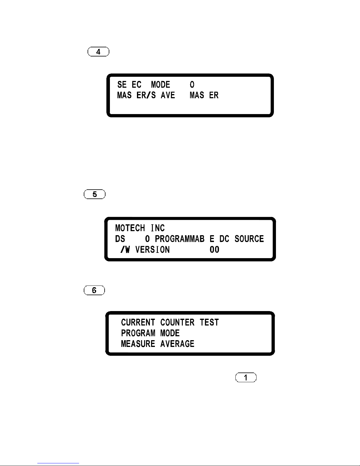
4. SERIES/PARALLEL SETTING
Press
in the second page of Menu Setting to enter
SERIES/PARALLEL page.
L
TL
T
FF=
=
T
SELECT MODE:
Choose the Series/Parallel mode.
MASTER/SLAVE:
Refer to Sec 5.8:
Series/Parallel
Setting
for the detailed setting
procedure of MASTER/SLAVE mode.
5. INFORMATION
Press in the second page of Menu Setting to enter
INFORMATION page.
63F4
.
L
:
1
.
6. SPECIAL TEST FUNC
Press
in the second page of Menu Setting to enter SPECIAL
TEST FUNCTION page.
.
1
3
2 .
.
6.1 CURRENT COUNTER TEST: Press to enter the
CURRENT COUNTER TEST page.
Page 30
21
= 1 . = .
:
.
FF= 1 .
:
Refer to Sec 5.10:Current Counting for the detailed setting procedure.
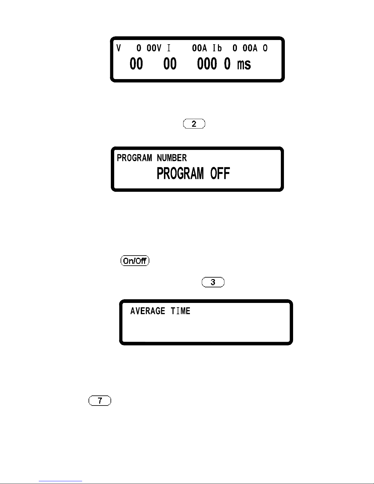
6.2 PROGRAM MODE:Press
to enter the PROGRAM MODE
page.
1=
Before running the program, user needs to input the programs
through the USB or GPIB interface into DS3640/DS6024/
DS8018/DS10014. Users may save 10 programs (program
number 1 through 10) in the hardware and recall here in this
Program Mode page by selecting the program number and then
pressing
to execute the program.
6.3 MEASURE AVERAGE:Press
to enter the MEASURE
AVERAGE page.
2=
AVERAGE TIME:
Set the measure average time.
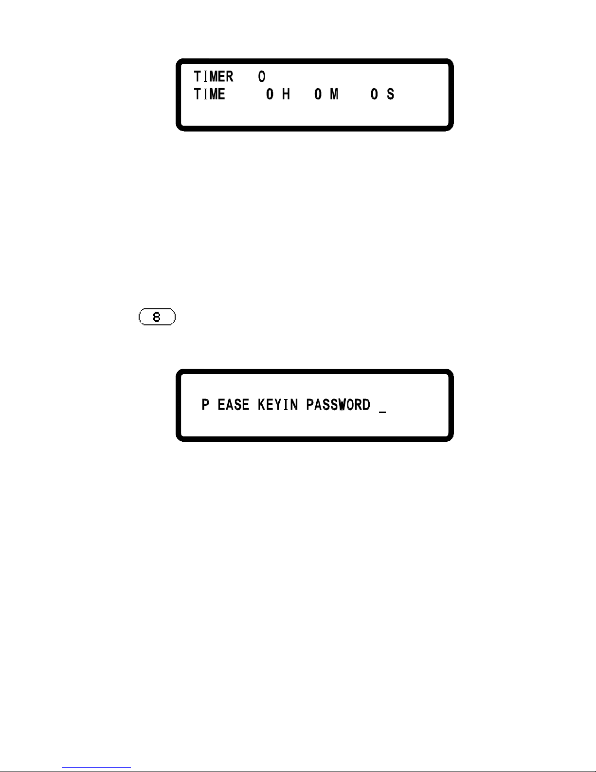
7. TIMER CONTROL
Press
in the third page of Menu Setting to enter TIMER
CONTROL page.
Page 31
22
=
=
FF
r ni ec
TIMER:
Turn on/off TIMER function.
TIME:
Set up OUTPUT ON time (Max:999Hr 59Min
59Sec)
8. CALIBRATION
Press
in the third page of Menu Setting to enter CALIBRATION
page. Users shall enter the password and then access to the calibration
procedures.
:
L
8.1 Equipment Requirments
1. 5 1/2 DVM (HP34401A)
2. Shunt for Current Calibration (100A/10 m)
Page 32
23
Figure 1
8.2 Calibration Items and Procedures
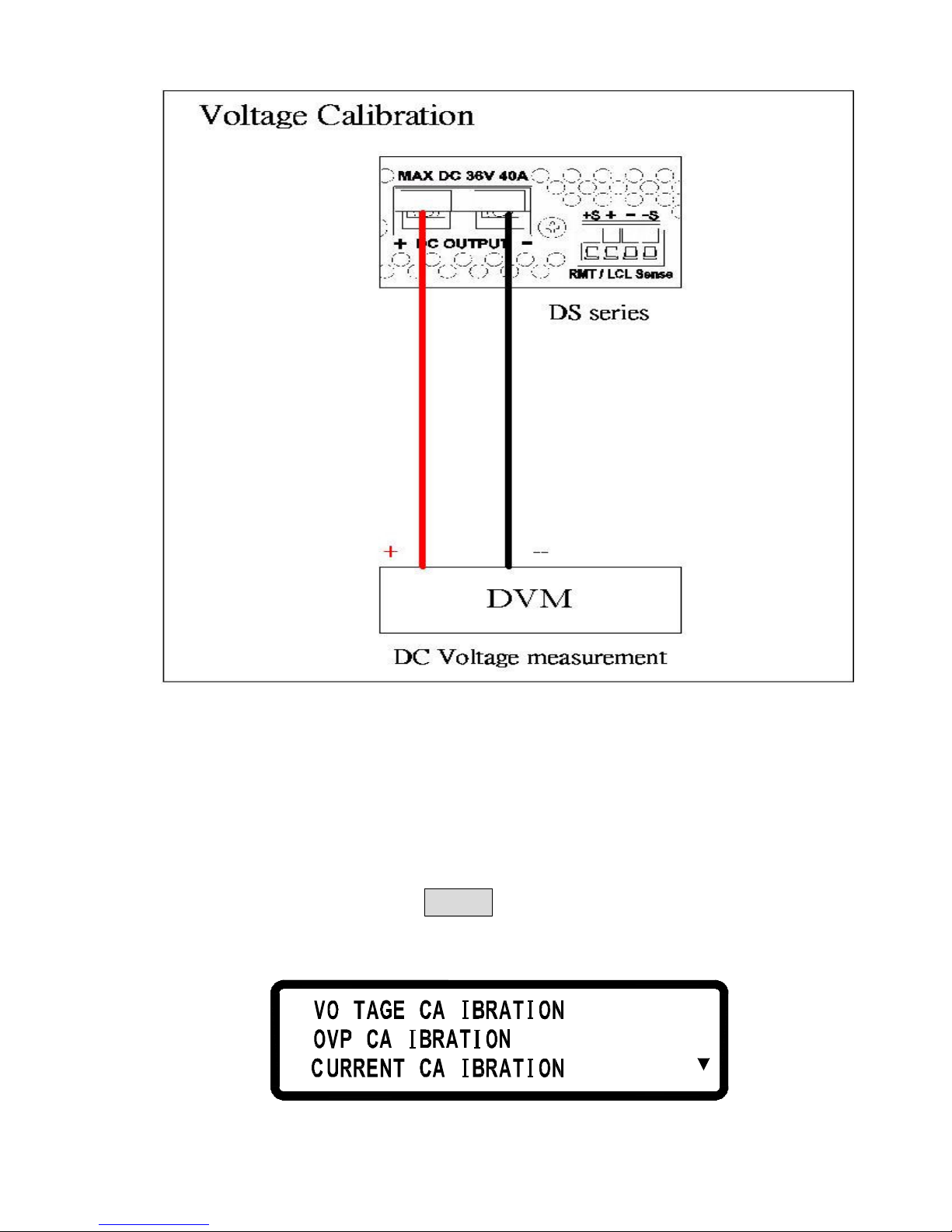
8.2.1 VOLTAGE CALIBRATION
A. Connect DS3640 output terminal to DVM (as shown in Figure 1). Then,
select DVM at DC volatage measurement and turn on DS3640. Once
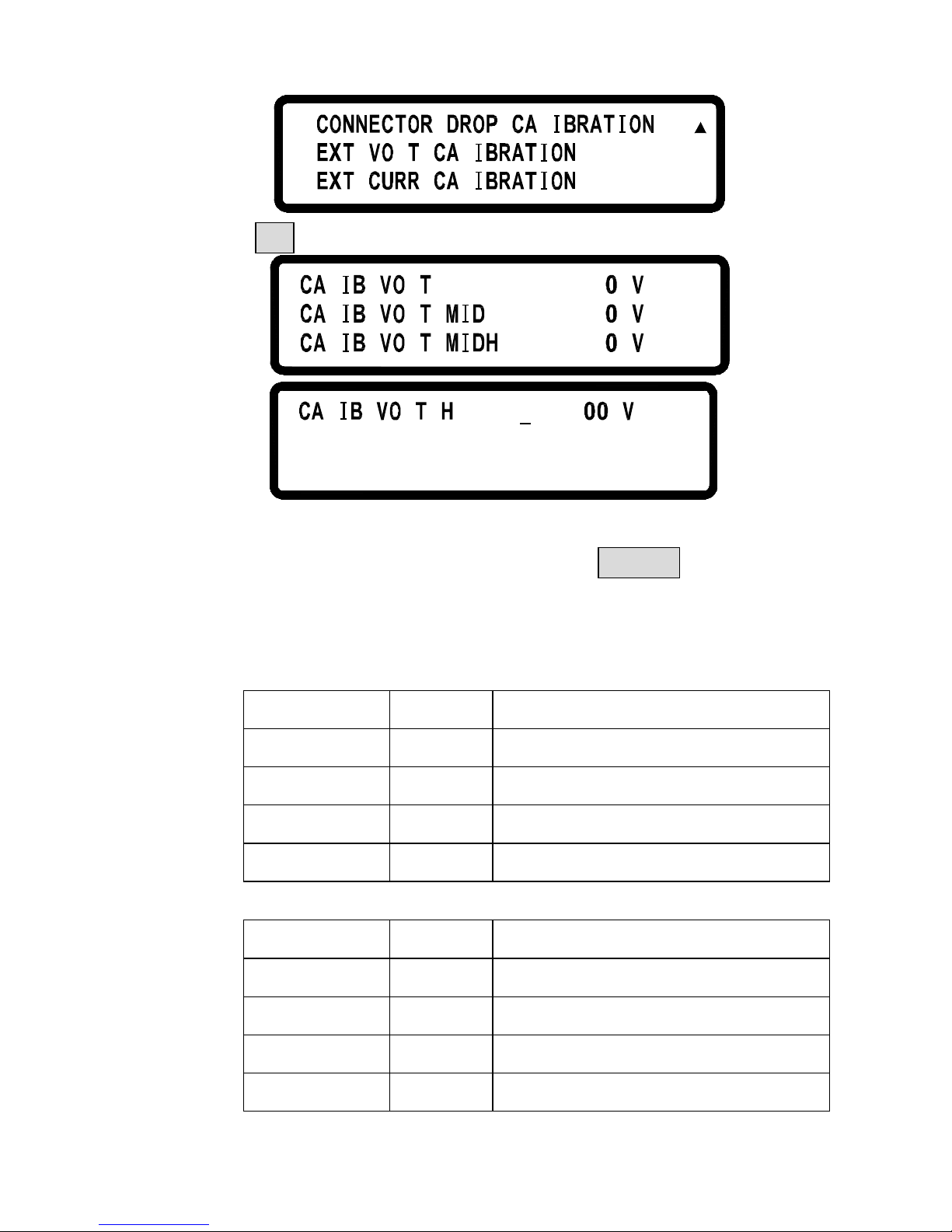
entering main page, press MENU and select8.Calibrationand key
in password “13579” to enter the following calibration main page
(Items
L1 .
3
2
.
.
L
L
L
Page 33
24
L
L
L
L
4 .
6
5 .
.
B. Press 1 to access Voltage calibration procedure
L
o 468.1=L
5
21=L
= 2 4
455.
11L
L
LL
L
LL i 87.53=
C. According to voltage value displayed on DVM, please fill in with
the corresponding function and press ENTER. If any DVM
read-back value at each voltage function does not fit with the
following table, please inspect the hardware.
DS 3640
Function
Setting Range of Transformation Value
Lo 1.8V 1.5 ~ 2.0 V
MIDL 12V 10 ~ 13 V
MIDH 24V 21 ~ 25 V
Hi 32.4V 31 ~ 34 V
DS 6024
Function
Setting Range of Transformation Value
Lo 3V 2.4 ~ 3.6 V
MIDL 20V 18 ~ 22 V
MIDH 40V 36 ~ 44 V
Hi 57V 53 ~ 61 V
Page 34
25
DS 8018
Function
Setting Range of Transformation Value
Lo 4V 3.6 ~ 4.4 V
MIDL 26V 23.5 ~ 28.5 V
MIDH 53V 48 ~ 58 V
Hi 76V 69 ~ 83 V
DS 10014
Function
Setting Range of Transformation Value
Lo 5V 4.5 ~ 5.5 V
MIDL 33V 29.7 ~ 36.3 V
MIDH 66V 59 ~ 72 V
Hi 95V 85 ~ 104 V
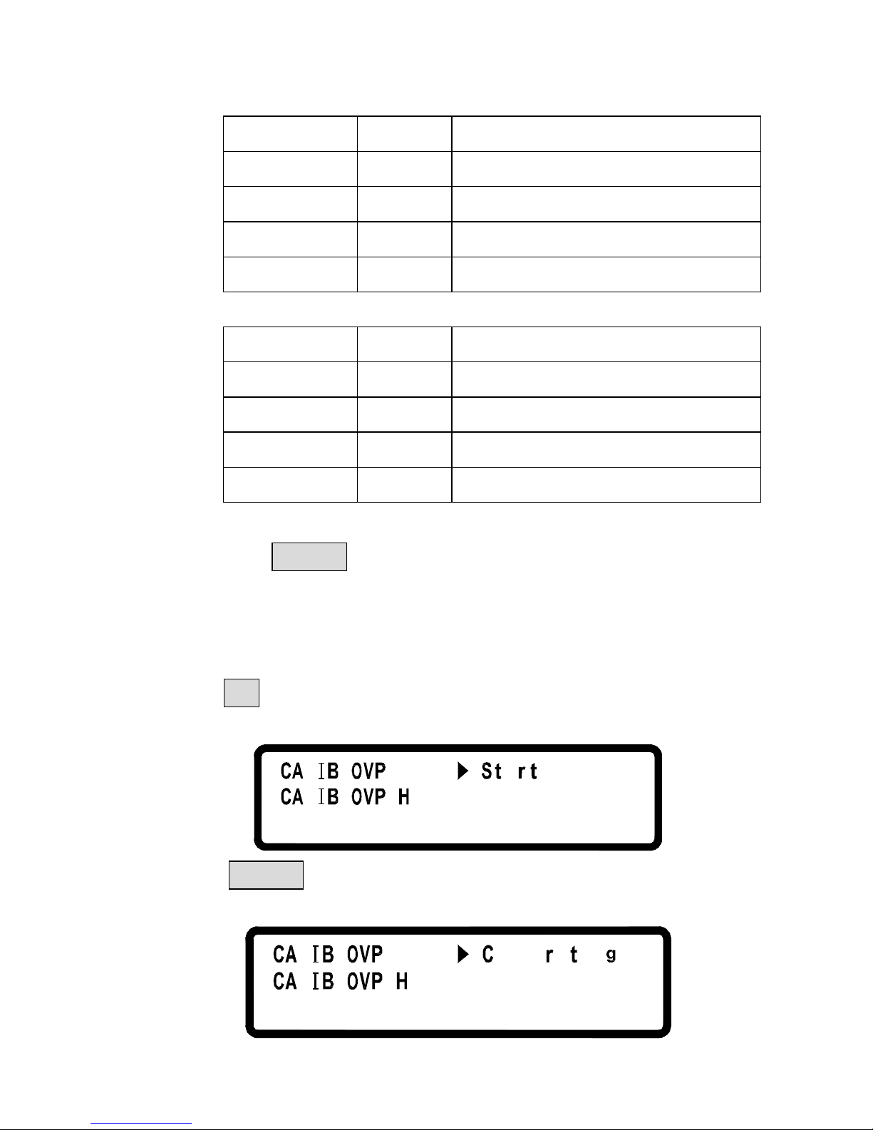
D. When pressing ENTER at Hi function, the calibration value will
be stored in FLASH and returned to calibration main page (Items
.
8.2.2 OVP CALIBRATION
A. Press 2 in the calibration main page to enter OVP calibration
page.
L
L
a=oL
=
i
B. Press ENTER to access OVP calibration procedure at Low
function.
L
L
n
i
ab
i
laLo=
=i
...
Page 35
26
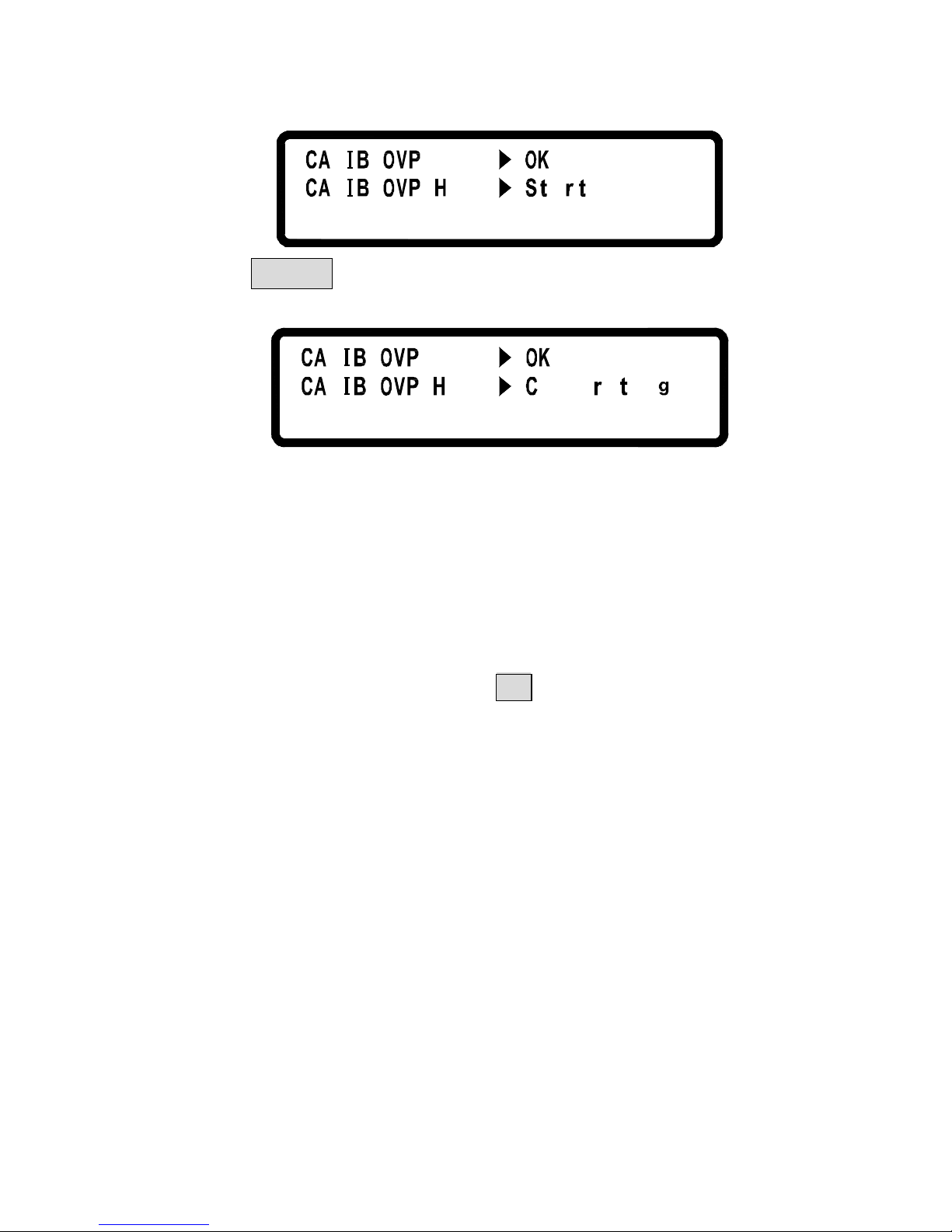
C. Jump to Hi function when completed.
L
L
Lo =
=i a
D. Press ENTER to access OVP calibration procedure at High
function.
L
L
Lo =
a=
i
lib ain
. . .
E. After completed, calibration value will be stored in FLASH and
returned to calibration main page (Items
F. If calibration is not completed in 10 seconds after starting, please
inspect OVP circuit.
8.2.3 CURRENT CALIBRATION
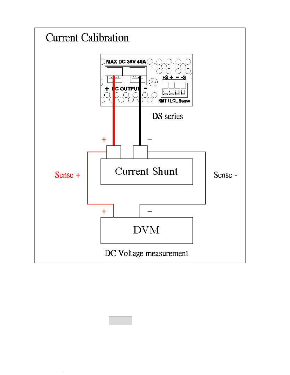
A. Connect two output terminals of DS3640 to two ends of current shunt,
and connect DVM to the sensor of current shunt to measure DC
voltage as shown Figure 2. Press 3 to enter current calibration
page.
Page 36
27
Figure 2
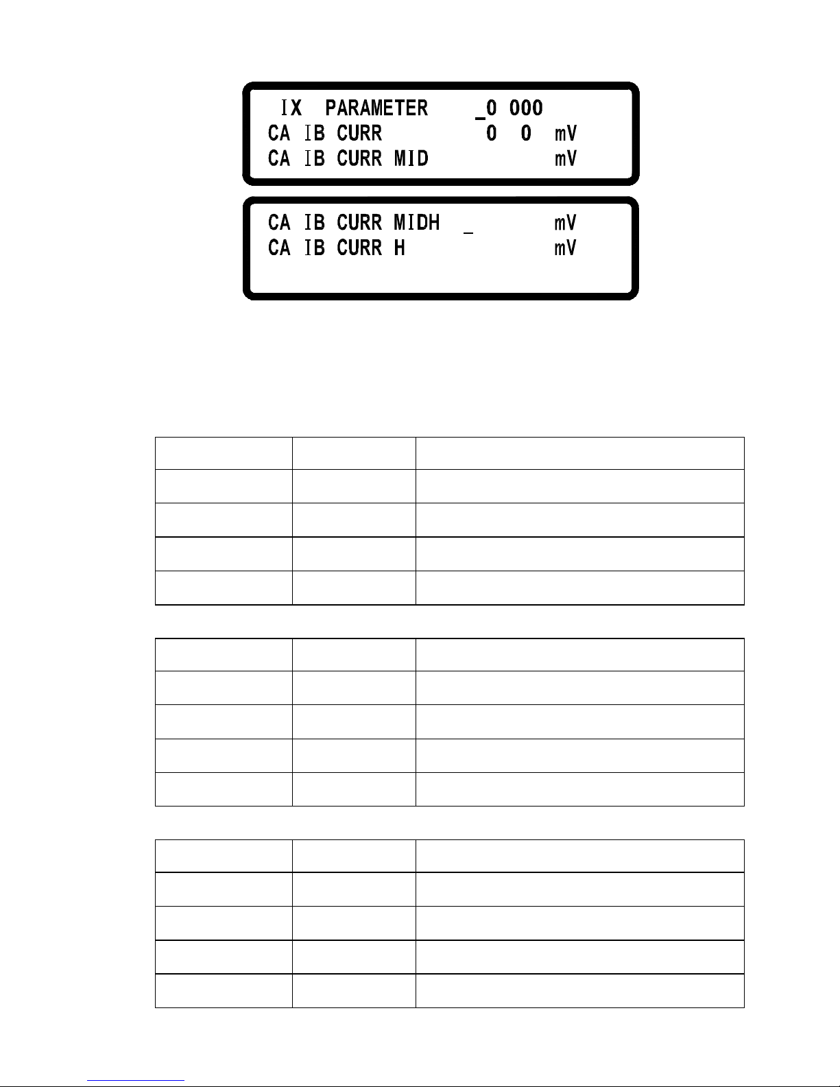
B. First, input transformation parameter (resistance of current shunt, m)
of current measurement fixture.
According to voltage value shown on DVM, fill in with the corresponding
function and press ENTER key.
Page 37
28
F
.
L
L
= 1
.
2
Lo =
=L 1 8
6.
.
8 9
4
1
2 .= 58 246
7i3= 5
.
7 5 9
L
L
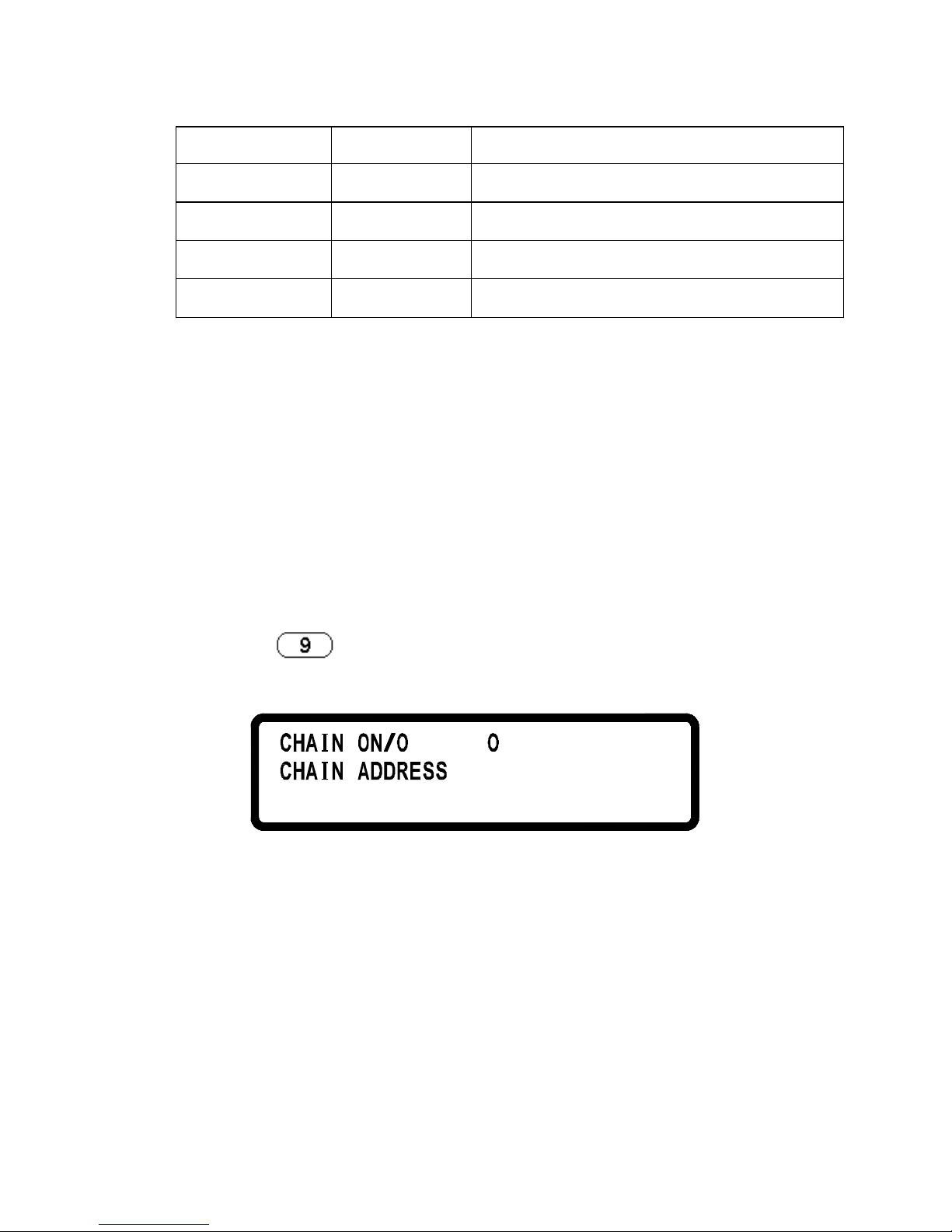
C. Please inspect the hardware, if the current value is inconsistent
with the value in the tolerance error table after the value of
calibration function is transformed to actual current value.
DS 3640
Function
Setting
Range of Transformation Value
Lo 0.1A 0 ~ 0.5 A
MIDL 13A 11 ~ 14 A
MIDH 26A 23 ~ 27 A
Hi 38A 34 ~ 39 A
DS 6024
Function
Setting
Range of Transformation Value
Lo 0.06A 0 ~ 0.5 A
MIDL 7.8A 6.6 ~ 9 A
MIDH 15.6A 14 ~ 17.2 A
Hi 22.8A 21 ~ 24.6 A
DS 8018
Function
Setting
Range of Transformation Value
Lo 0.045A 0 ~ 0.1 A
MIDL 5.9A 5.3 ~ 6.5 A
MIDH 12A 10.8 ~ 13.2 A
Hi 17A 15.3 ~ 18.7 A
Page 38
29
DS 10014
Function
Setting
Range of Transformation Value
Lo 0.03625A 0 ~ 0.1 A
MIDL 4.7A 4.2 ~ 5.2 A
MIDH 9.5A 8.55 ~ 10.45 A
Hi 13.7A 12.33 ~ 15.07 A
D. The calbriation value will be stored in FLASH after pressing
ENTER at Hi function.
8.2.4CONNECTOR DROP CALIBRATION (Not available)
8.2.5 EXTERNAL VOLTAGE CALIBRATION (Not available)
8.2.6 EXTERNAL CURRENT CALIBRATION (Not available)
9.
Series Connection Control Setting (CHAIN)
Press
in Menu setting page to enter CHAIN SETTING
page.
FF=FF
1=
CHAIN ON/OFF
On/Off Series Connection Mode
CHAIN ADDRESS
Setting Address (1 – 31)
For the detailed setting information, please
refer to Sec. 5.12 SERIES CONNECTION FUNCTION.
Page 39
30
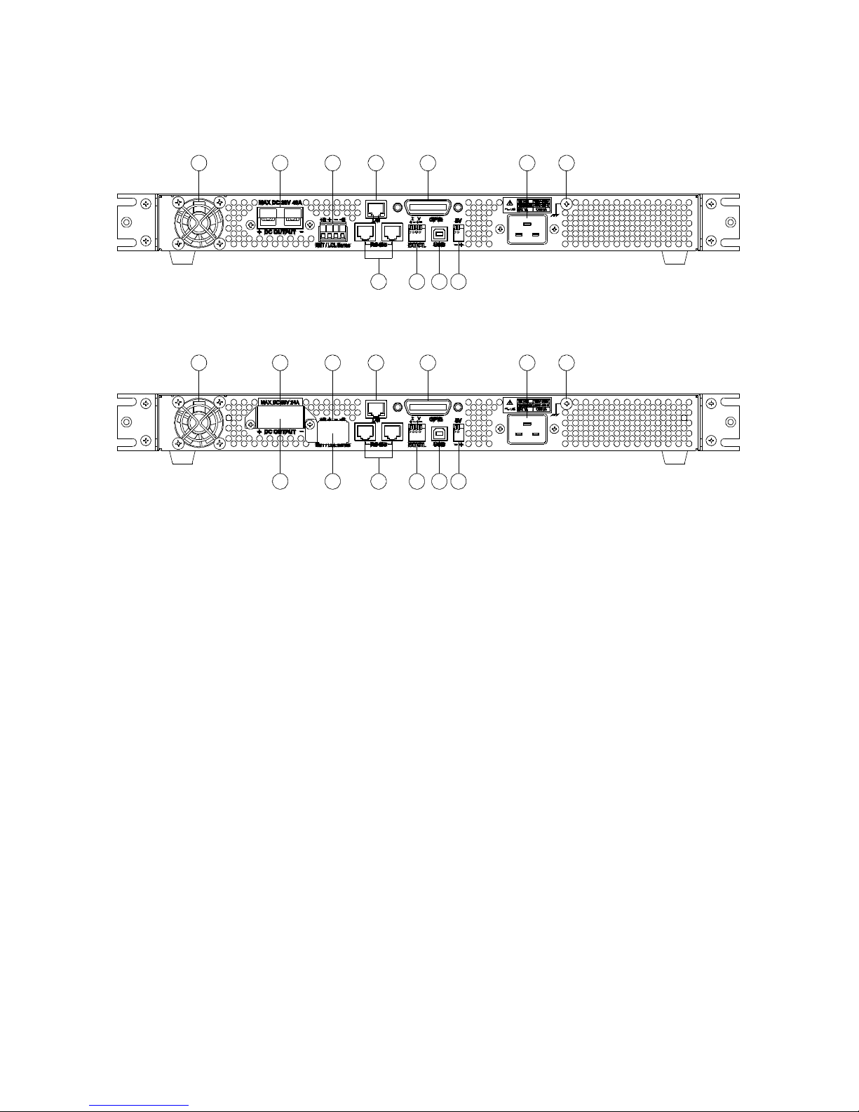
4.1.2 Rear Panel
19 2016 17 18
26 25 24 23
21 22
Rear Panel of DS3640
17 18
28 27 261625 24
19 20
23
21 22
Raer Panel of DS6024/DS8018/DS10014
(16) Cooling fans:
Automatically adjust fan’s rpm according to the internal tempeture. This
is a wisdom design.
(17) Power output terminal:
Please pay attention to the correct polarities when doing the connections.
(18) RMT/LCL Sense:
When Remote sense is selected, the wire connection shall be as follows
(shown in the figure below):positive sense (+S) and positive lead (+) of
the DC output are connected to the positive end (+) of the device,
whereas negative sense (-S) and negative lead (-) of the DC output are
connected to the negative end (-) of the device under test. This
connection will compensate the voltage dropped due to the current flow
through the long power wires (the maximum compensating voltage is
2V).
Page 40
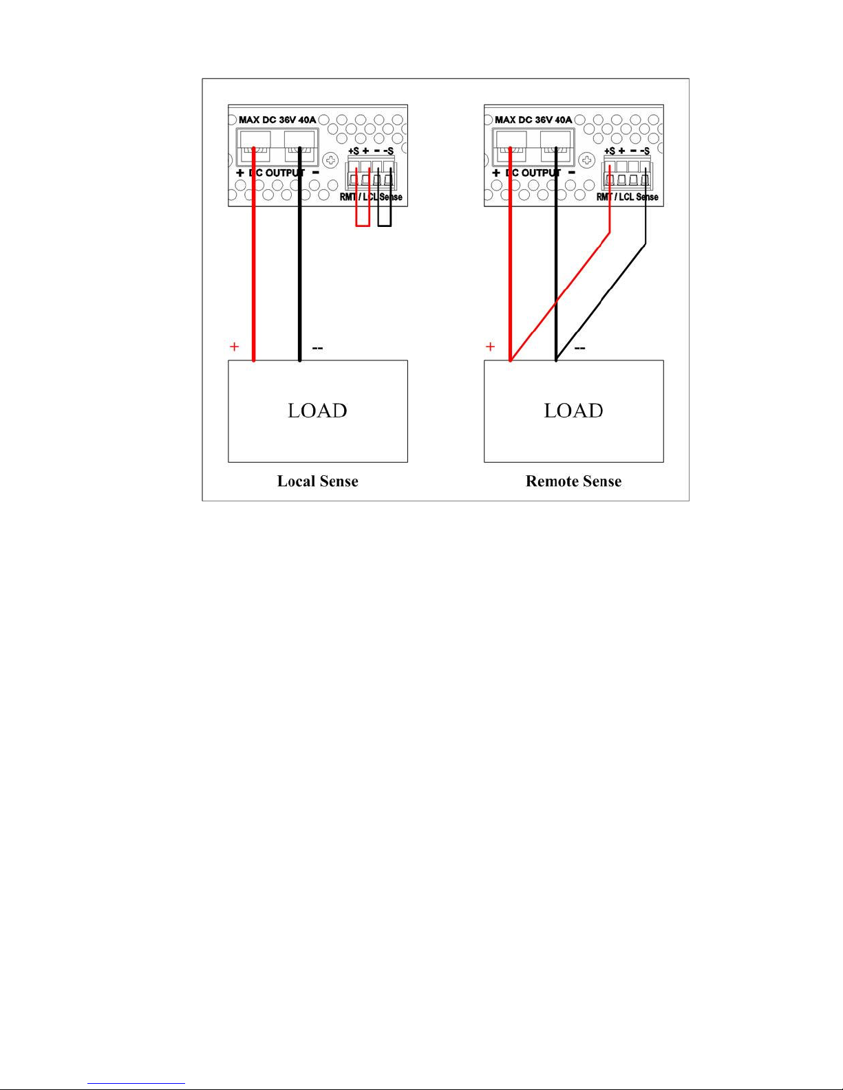
31
When Local sense is selected, the wire connection shall be as follows
(shown in the figure above):positive sense (+S) is connected to the
positive lead (+) and negative sense (-S) is connected to the negative lead
(-), whereas the positive lead (+) of the DC output is connected to the
positive end (+) of the device and the negative lead (-) of the DC output
is connected to the negative end (-) of the device under test. When this
sensing mode is selected the power wires from the DC ouput leads to the
device under test shall be as short as possible.
(19) LAN (optional):
The ETHERNET interface connector
(20) GPIB (optional):
The GPIB interface connector
(21) AC power input:
The power receptacle is for power source within 100Vac ~ 240Vac.
(22) Earthing point:
Used for earth ground connection.
Page 41

32
(23) 5V/1A Output:
DS3640/DS6024/DS8018/DS10014 offers an extra output that the
constant output voltage is 5V and the maximum output current is 1
amperes. This extra power supply can be switched on or off in the
System Setting menu.
(24) USB :
It is the USB interface connector.
(25) EXT CTL:
DS3640/DS6024/DS8018/DS10014 offers the capability of setting the
output voltage/current by adjusting an external input voltage/resistance.
The range of the external input voltage is 0 ~ 10Vdc or 0 ~ 5V which is
corresponding to the output voltage of 0 ~ 36V for DS3640 and 0 ~ 60V
for DS6024 and 0 ~ 80V for DS8018 and 0 ~ 100V for DS10014 and
corresponding to the output current of 0 ~ 40A for DS3640 and 0 ~ 24A
for DS6024 and 0 ~ 18A for DS8018 and 0 ~ 14.4A for DS10014. The
range of the external resistance is 0 ~ 5K ohm which is corresponding to
the output voltage of 0 ~ 36V for DS3640 and 0 ~ 60V for DS6024 and 0
~ 80V for DS8018 and 0 ~ 100V for DS10014 and corresponding to the
output current of 0 ~ 40A for DS3640 and 0 ~ 24A for DS6024 and 0 ~
18A for DS8018 and 0 ~ 14.4A for DS10014.
(26) RS485:
While at series-parallel connection or multi-unit series connection,
RS485 interface can be used for communications and synchronize
signals between master and slavers.
(27) Protection shield of the RMT/LCL Sense connector
(DS6024/DS8018/DS10014):
WARNING:
When the RMT/LCL Sense is not activated and/or not
used, the protection cover shall be keeping in shielded
state, do not dismantle it that might get an electric shock.
Page 42

33
(28) Protection shield of the output leads (DS6024/DS8018/DS10014):
WARNING:
This PRODUCT is designed meeting safety code and has
passed the related qualification test. To assure user the
consistency of safety, user should, after equipping DC
output cable according to field condition, follow the
Manual’s suggestion to install the fixing sheets. In case no
output cable is connected, close the protection shield and
fasten the screws in so as to protect user from getting an
electric shock or other hazards.
Page 43
34
5. Operation Interpretation
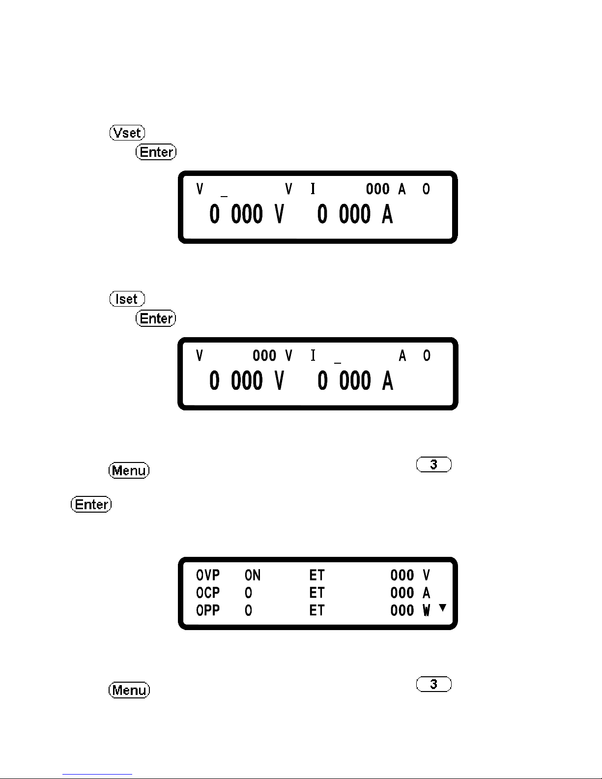
5.1 Voltage Setting
Press
and set the output voltage by press numerical keys directly, and
then press
to confirm it and complete the setting.
=
.
.= 15
.
FF
5.2 Current Setting
Press and set the output current by press numerical keys directly and
then press to confirm it and complete the setting.
=
.
FF.63=
.
5.3 Over-voltage Protection OVP
Press to enter the Configuration page and press to enter the
PROTECTION setting page. Then, using the knob to set OVP to ON and press
to confirm it. Now the cursor will move to the value setting for the
OVP on the right hand side. Enter the OVP value here by press the numerical
keys.
F
F
S = 3 .8
S
S =
=
204
41 4..
F
F
=
=
=
5.4 Over-current Protection OCP
Press to enter the Configuration page and press to enter the
PROTECTION setting page. Then, using the knob to set OCP to ON and press
Page 44
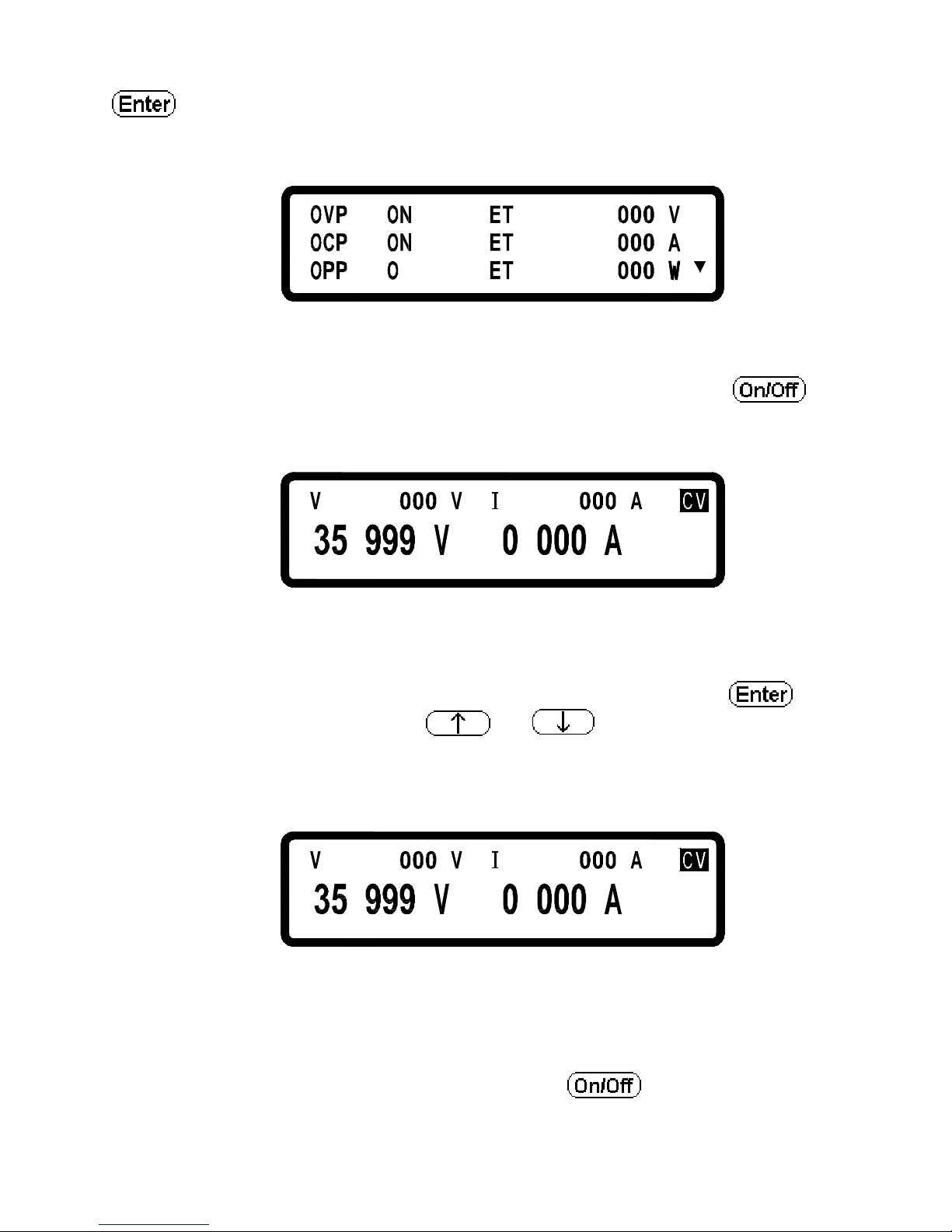
35
to confirm it. Now the cursor will move to the value setting for the
OCP on the right hand side. Enter the OCP value by press the numerical keys.
F
=
=
=
F
8
.
3
=
S
S
S
=
=
0
24
41 4
.
.
5.5 Voltage Output
After the voltage, current and protection point settings, press
to
output voltage. User shall be able to recognize the setting values and the actual
output values from the LCD.
.= 1
5
.
.63=
.
5.6 Voltage Output Controlled by Knob controller
When the output is ON, user can may still increase or decrease the output
voltage by turnning the knob controller. The procedure is:press
and
cursor appears in response; press
or
to move the cursor to the
digit that change will make and turn the knob to increase or decrease the output
voltage. The changes of the voltage seting and the output voltage can be
observed concurrently.
.= 1
5
.
.63=
.
5.7 Timer Function
When the “ Timer Setting” function at item 7 of system parameters is ON, it
will activate the timer. After time setting is made, return to the main page. After
setting up the output current & voltage and press
to output, the screen
now will show the countdown of Timer that when it counts down to zero,
Page 45
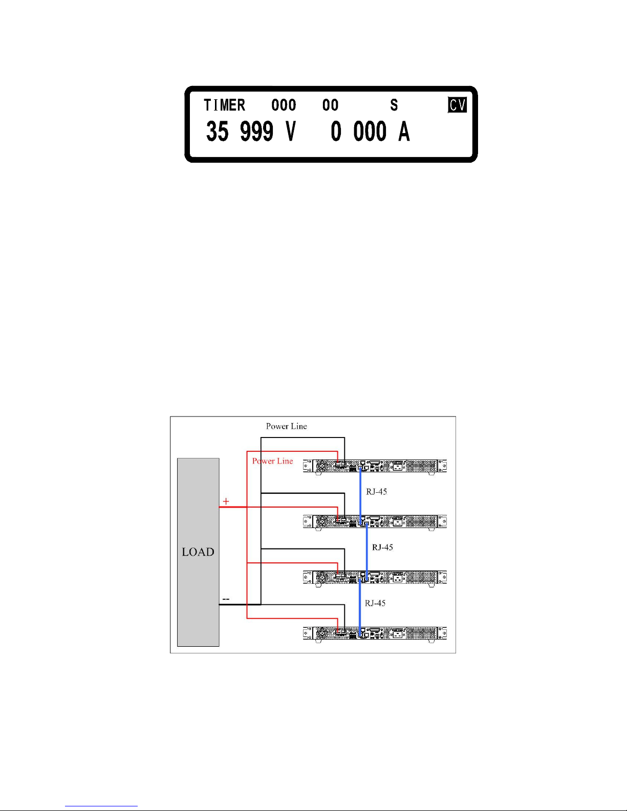
36
system will turn off the output automatically.
=
.
ce55
::
.
5.8 Make Series (Cascade)/Parallel Setting
The DS3640/DS6024/DS8018/DS10014 uses the series/parallel mode (4 sets in
maximum) that can apparently improve the power supplying capability. Under
the 4-set parallel mode of DS3640 units, the combines unit can offer 36V/160A
power output. And under the 4-set cascading mode of DS10014 units, the
combined unit can offer 400V/14.4A output. Note that you cannot perform both
parallel and series mode at the same time. Series connection will be off once
Series (Cascade)/Paralled connection function is turned on.
5.8.1 Parallel Connection Setting
While connecting four sets of DS3640/DS6024/DS8018/DS10014 in parallel,
the wiring is shown in the following figure:
After wiring is complete, select one DS3640/DS6024/DS8018/DS10014 as the
Master and the other three are Slave A, B and C. After the DS3640/DS6024/
DS8018/DS10014 is set to the Master, it will start searching for all Slaves that
are connected to the Master. Therefore, in order to reach the control status, user
Page 46
37
must set up the Slaves before the Master is set.
To set a DS3640/DS6024/DS8018/DS10014 to the slave mode, press
,
, and
in the main page to enter the series/parallel setting option.
And then select the parallel mode by turning the knob (SCPI command is
“ PS:MODE PARALLEL”) and then press to confirm. It will continue
to the next line for the MASTER/SLAVE selection. Turning the knob to select
SLAVE A (SCPI command is “ PS:TYPE SLAVEA”) for the
DS3640/DS6024/DS8018/DS10014 and press to confirm the setting.
Using the same procedure to set up SLAVE B and C for another two (2)
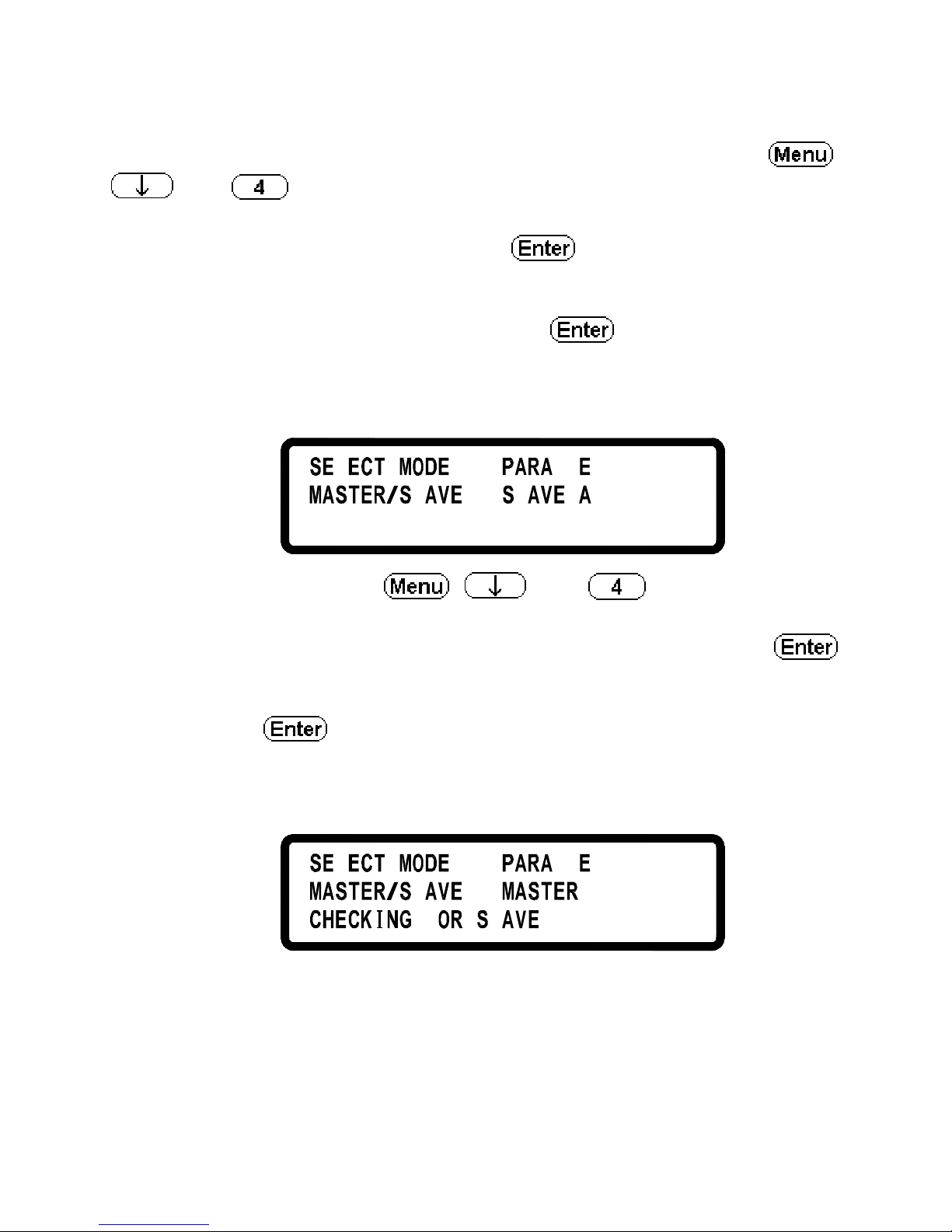
DS3640/DS6024/DS8018/DS10014 as graphically demonstrated below.
LLL=
= LL
L
To set the master unit, press
,
, and
in the main page to
enter the series/parallel setting option. And then use the knob to select the
parallel mode (SCPI command is “ PS:MODE PARALLEL”) and press
to confirm. It will continue to the next line for the MASTER/SLAVE selection.
Use knob again to select MASTER (SCPI command is “ PS:TYPE MASTER”)
and then press to confirm. After it is confirmed as the Master the
DS3640/DS6024/DS8018/DS10014 will start searching for all Slaves, as
graphically demonstrated below.
= LL L
=
F L
...
L
L
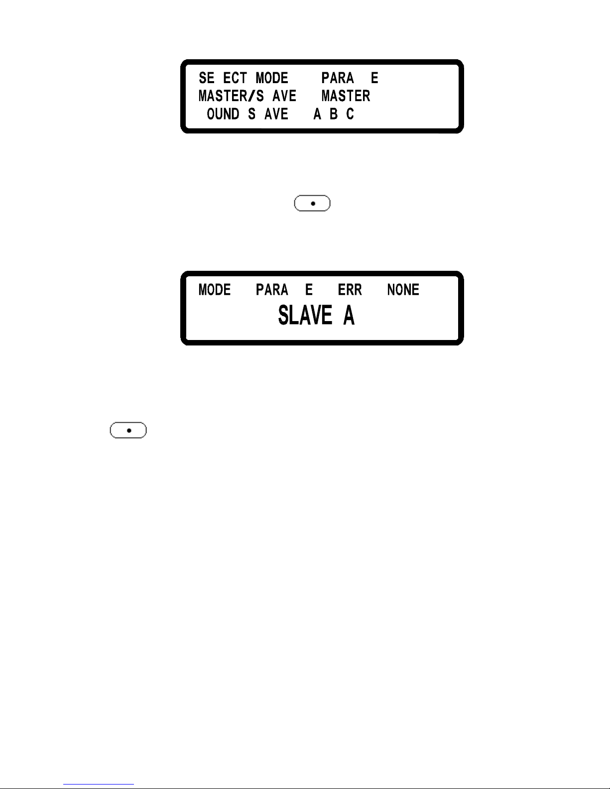
If wiring is correct, screen will appear:
Page 47
38
L
= LL L
=
:
L
L
F
After receiving the control order from the Master, all Slaves will be locked on
the SLAVE page that all keys except are disabled so that slaves can not
be operated by press keys except controlled by the Master as graphically
demonstrated below.
: :
LLL
Once the Master and Slave settings are done, users can then operate the Master
only to set up the output voltage and current.
To release from this operation mode (parallel operation mode in this example),
press (LCL) to access to the series/parallel setting page and turning the
knob to select OFF for series/parallel selection to leave the series or parallel
operation mode and back to the local operation mode that the
DS3640/DS6024/DS8018/DS10014 can be controlled by press the keys again.
It shall not change the operation mode while DS3640/DS6024/DS8018/DS10014
is in output state or it will cause the Master’s communication failure and
display error message.
5.8.2 Cascade Setting
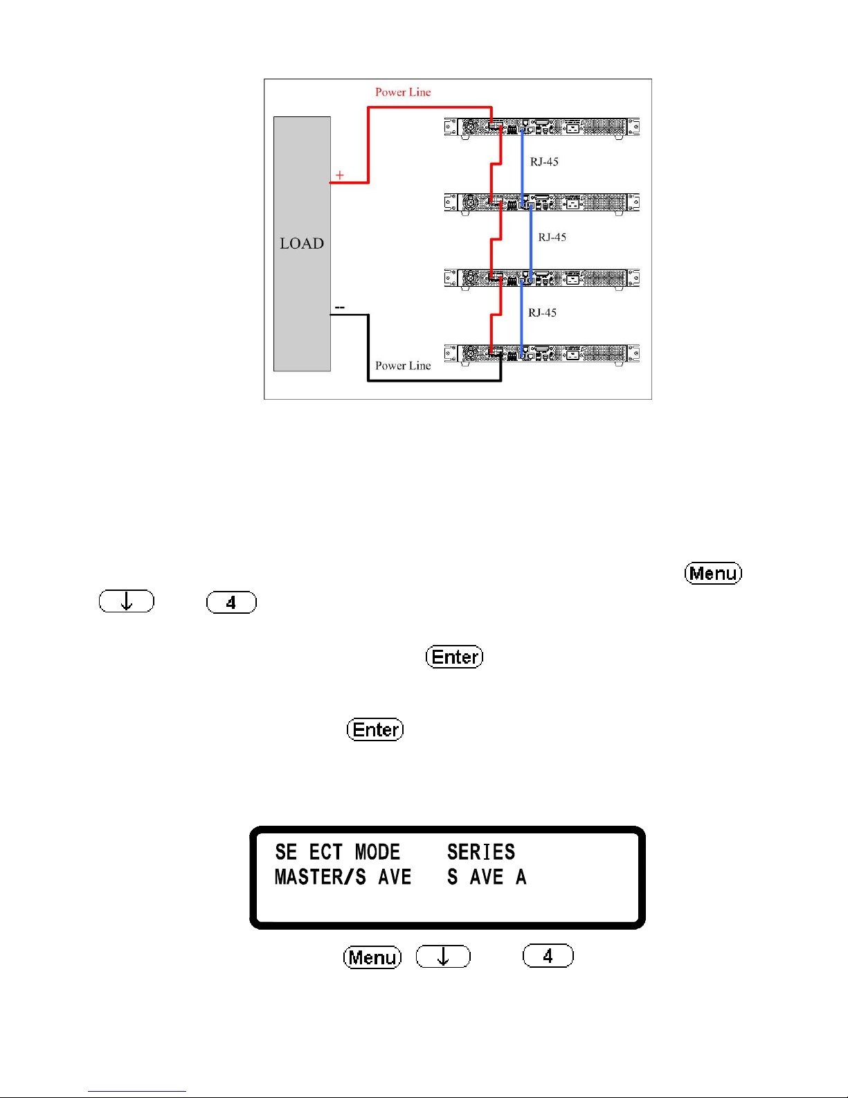
While connecting four sets of DS3640/DS6024/DS8018/DS10014 in cascade,
the wiring is shown in the following figure.
Page 48
39
After wiring is complete, select one DS3640/DS6024/DS8018/DS10014 as the
Master and the other three as the Slave A, B, and C. After the DS3640/DS6024/
DS8018/DS10014 is set to the Master, it will start searching for all Slaves that
are connected to the Master. Therefore, in order to reach the control status, user
must set up the Slaves before the Master is set.
To set a DS3640/DS6024/DS8018/DS10014 to the slave mode, press
,
, and
in the main page to enter the series/parallel setting option.
And then select the SERIES mode by turning the knob (SCPI command is
“ PS:MODE SERIES”) and then press to confirm. It will continue to
the next line for the MASTER/SLAVE selection. Turning the knob to select
SLAVE A (SCPI command is “ PS:TYPE SLAVEA”) for the DS3640/DS6024/
DS8018/DS10014 and press to confirm the setting. Using the same
procedure to set up SLAVE B and C for another two DS3640/DS6024/DS8018/
DS10014.
L
L =
= L
To set the master unit, press
,
,
and
in the main page to
enter the series/parallel setting option. And then use the knob to select the
Page 49
40
series mode (SCPI command is “ PS:MODE SERIES”) and press to
confirm. It will continue to the next line for the MASTER/SLAVE selection.
Use knob again to select MASTER (SCPI command is “ PS:TYPE MASTER”)
and then press to confirm. After it is confirmed as the Master the
DS3640/DS6024/DS8018/DS10014 will start searching for all Slaves, as
graphically demonstrated below.
=
=
F L
.. .
L
L
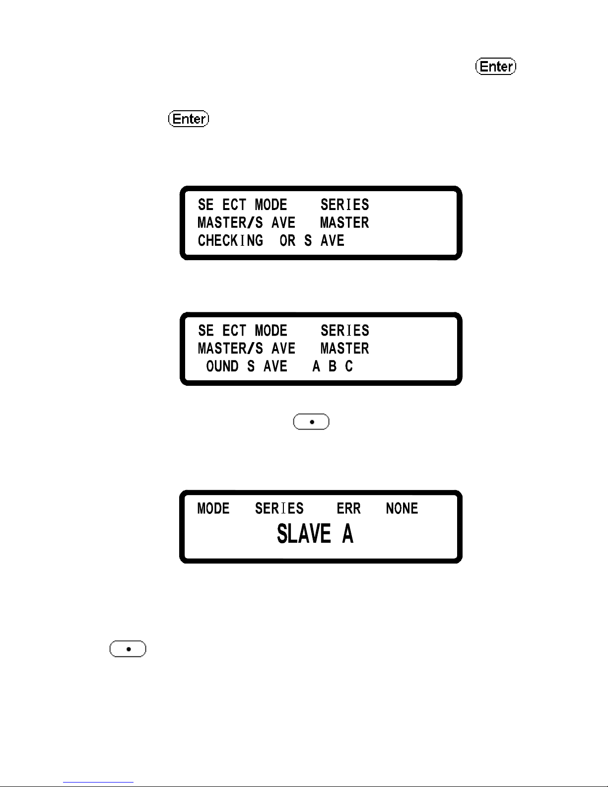
If wiring is correct, screen will appear:
L
=
=
:
L
L
F
After receiving the control order from the Master, all Slaves will be locked on
the SLAVE page that all keys except are disabled so that slaves can not
be operated by press keys except controlled by the Master as graphically
demonstrated below.
::
Once the Master and Slave settings are done, users can then operate the Master
only to set up the output voltage and current.
To release from this operation mode (series operation mode in this example),
press (LCL) to access to the series/parallel setting page and turning the
knob to select OFF for series/parallel selection to leave the series or parallel
operation mode and back to the local operation mode that the
DS3640/DS6024/DS8018/DS10014 can be controlled by press the keys again.
It shall not change the operation mode while DS3640/DS6024/DS8018/DS10014
Page 50
41
is in output state or it will cause the Master’s communication failure and
display error message.
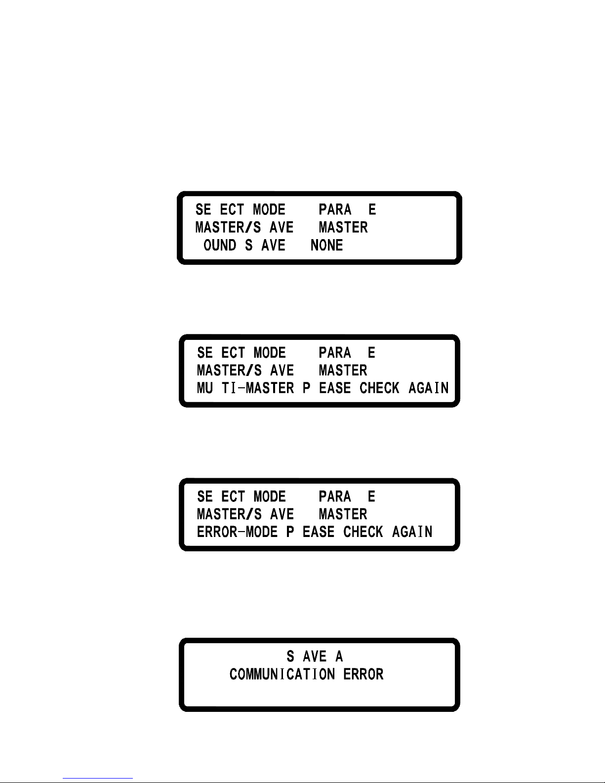
5.8.3 Error Message of Series/Parallel Connection
If RS485 wiring is wrong or the signal is not correct, Master will display the
following message in the page of searching Slaves:
L
LLL=
=
:
L
L
F
If more than one Master being set in the series/parallel operation mode, the
following message will be displayed.
L
L
L
= LL L
=
,
L
If one of the DS3640/DS6024/DS8018/DS10014 is set to different series/
parallel operation mode, screen will appear the following message.
L
L LLL=
=
,
L
After finishing setting procedure, if the Master cannot have a communication
with one of the three (3) Slaves, Master will present the following error
message (Slave A in this example).
L
!!!
Page 51
42
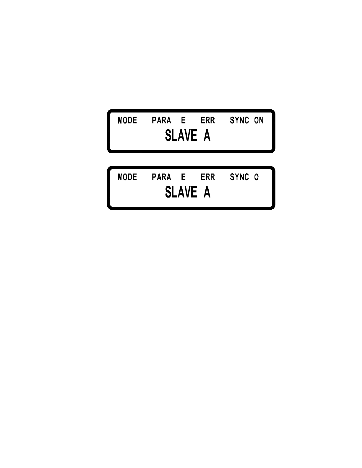
After finishing setting procedure, if a Slave receives only the output order sent
by Master but not receives the synchronous signal, then it will present the
following error messages. The error message “ SYNC ON” is shown when the
slave is not receiving the synchronous output ON signal. The error message
“ SYNC OFF” is shown when the slave is not receiving the synchronous output
OFF signal.
LL L
::
: :
LLL FF
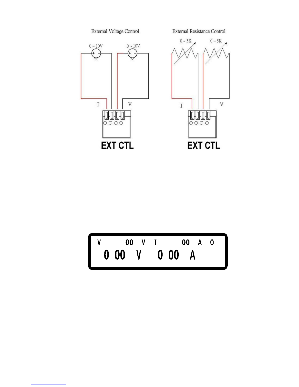
5.9 External Tuning Setting
DS3640/DS6024/DS8018/DS10014 provides the capability to control the
output voltages by an external voltage/resistance. The range of the external
voltage is in 0 ~ 10 Vdc or 0 ~ 5 Vdc and the range of the external variable
resistance is between 0 ~ 5 Kohm to control the output voltage (0 ~ 36V for
DS3640 and 0 ~ 60V for DS6024 and 0 ~ 80V for DS8018 and 0 ~ 100V for
DS10014) and the output current (0 ~ 40A for DS3640 and 0 ~ 24A for
DS6024 and 0 ~ 18A for DS8018 and 0 ~ 14.4A for DS10014). The wirings of
the external control is shown in the following figure.
Page 52
43
The external voltage control or external resistance control can be set in the
system setting page. Since the external control circuit uses a 12bit D/A
converter for 0 ~ 36V for DS3640 (or 0 ~ 60V for DS6024 or 0 ~ 80V for
DS8018 or 0 ~ 100V for DS10014) output voltage and 0 ~ 40A for DS3640 (or
0 ~ 24A for DS6024 or 0 ~ 18A for DS8018 or 0 ~ 14.4A for DS10014) output
current, therefore, the resolution of voltage and current will be different in
response. The screen thus will show as the following picture (accuracy is
10mV):
04 .=
.
FF.63=
.
5.10 Timer of Current Flow
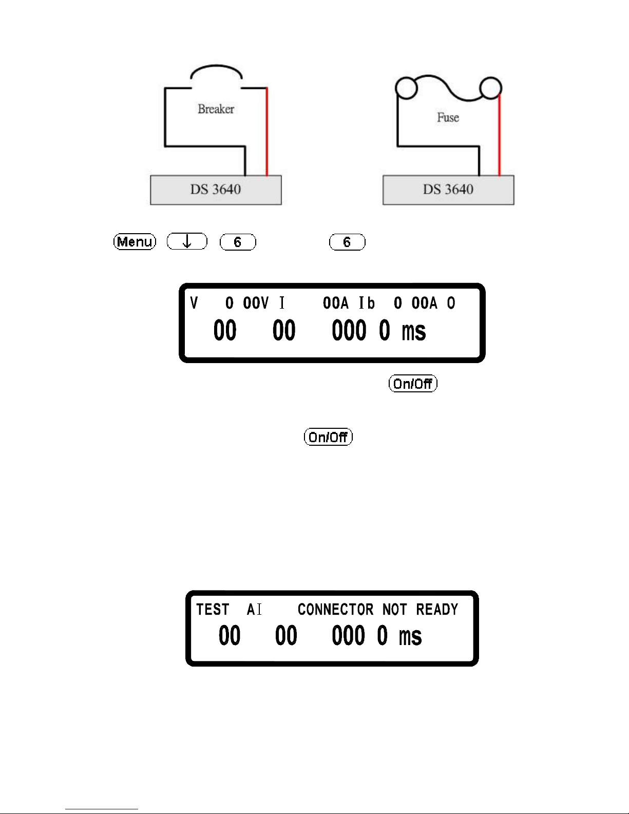
This function offers tests to the cutoff time of a breaker or a fuse. First, connect
the test objective to output terminal as shown below.
Page 53
44
Press
,
, ,
and then
in the main page to enter to
the current flow counter page.
= 1 . = .
:
.
FF= 1 .
:
After setting up output voltage/current and press to output, system
will start counting the timer till the breaker or fuse is open. The resolution of
the timer is 100us (0.1 ms) and the maximum counting period is one hour. If
counter doesn’t work after pressing , error occurs herein and screen
will display error message after two seconds. one of the following three cases
may happen:
A. Connector not ready
If a fuse is not properly connected to the output connector or a breaker under
test has not been switched to ON position, the screen will glimmer to show an
error message as shown below.
LF !:!
:
.
!
B. Current setting too large
The output current is set too big that a breaker is open or a fuse is burnt to open
before output current is reaching the setting value. The screen will glimmer to
Page 54
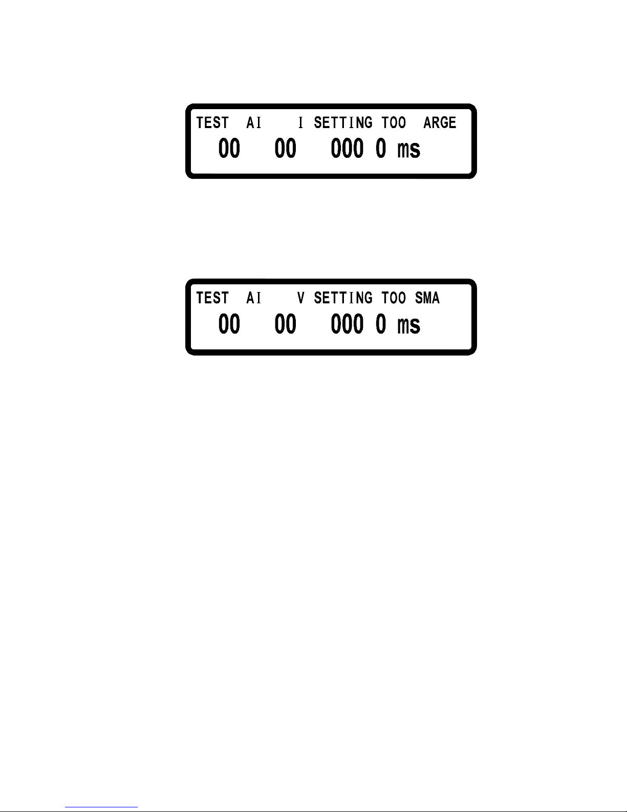
45
show an error message as shown below.
!F L:! L
:
.
!
C. Voltage setting too small
The voltage is set too small that output current is unable to reach the setting
value. The screen will glimmer to show an error message as shown below.
LF !:!
:
.
LL !
5.11 Programmable Capability (SCPI Command Only)
DS3640/DS6024/DS8018/DS10014 provides the capability for users to
program it. There are memory spaces to store 10 programs that can have 150
steps in total for setting purpose. Each program does not restrict the step
quantity, however, the sum of 10 programs are restricted to 150 steps. For each
program users can set up how many times to repeat the program. For each step
users may be able to set up the output voltage, current, and period of time (50
ms minimum) to output the settings. Please refer to Sec 7.5.2 (SCPI command
subsystem) for detail SCPI commands.
Page 55
46
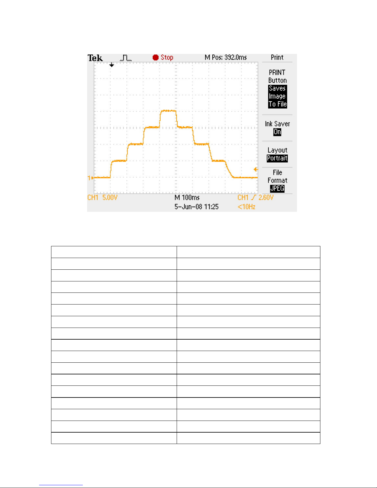
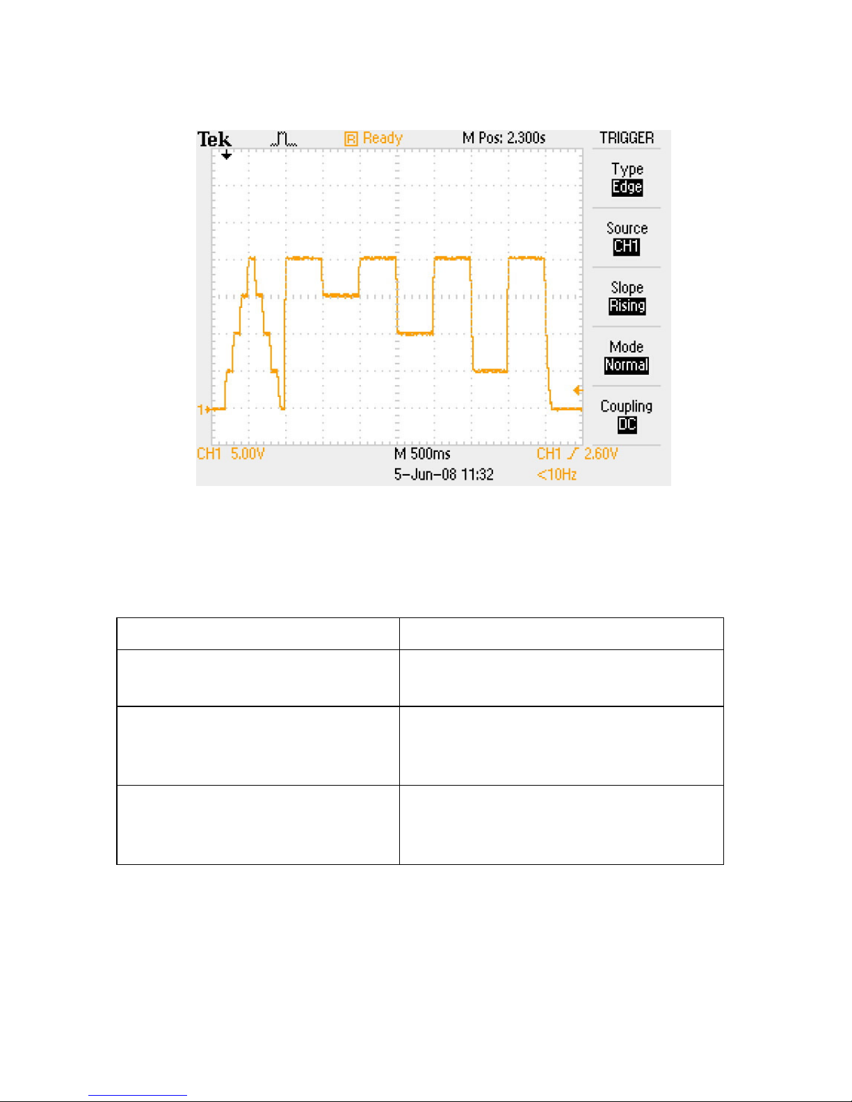
Example 1:
To output the wave form shown above, users may edit the program as the
following orders:
PROG 1 Choose program number
PROG:CLE Clear program 1 data
PROG:REP 0 No repeat (repeat one time for “ 1”)
PROG:TOTA 8 Set program 1 to have 8 steps in total
PROG:STEP 1 Following 3 settings are for step 1
PROG:STEP:CURR 1 Set output current to 1 ampere
PROG:STEP:VOLT 5 Output voltage is set to 5 volts
PROG:STEP:ONT 0.1 Output ON time is set to 0.1 sec
PROG:STEP 2 Following 3 settings are for step 2
PROG:STEP:CURR 1
PROG:STEP:VOLT 10
PROG:STEP:ONT 0.1
PROG:STEP 3 Choose step 3
PROG:STEP:CURR 1
PROG:STEP:VOLT 15
PROG:STEP:ONT 0.1
PROG:STEP 4 Choose step 4
Page 56
47
PROG:STEP:CURR 1
PROG:STEP:VOLT 20
PROG:STEP:ONT 0.1
PROG:STEP 5 Choose step 5
PROG:STEP:CURR 1
PROG:STEP:VOLT 15
PROG:STEP:ONT 0.1
PROG:STEP 6 Choose step 6
PROG:STEP:CURR 1
PROG:STEP:ONT 0.1
PROG:STEP 7 Choose step 7
PROG:STEP:CURR 1
PROG:STEP:VOLT 5
PROG:STEP:ONT 0.1
PROG:STEP 8 Choose step 8
PROG:STEP:CURR 1
PROG:STEP:VOLT 0
PROG:STEP:ONT 0.1
PROG:NEXT 0
Select next
program
to run after
program 1 is complete, 0 means stop
PROG:SAV
After edit, use
S
ave
command to store
program 1 in the hardware
P
ROG 1
PROG:RUN ON
T
o run the program stored in th
e
hardware, it shall select
program
number and then use RUN ON
command to execute the program.
Page 57
48
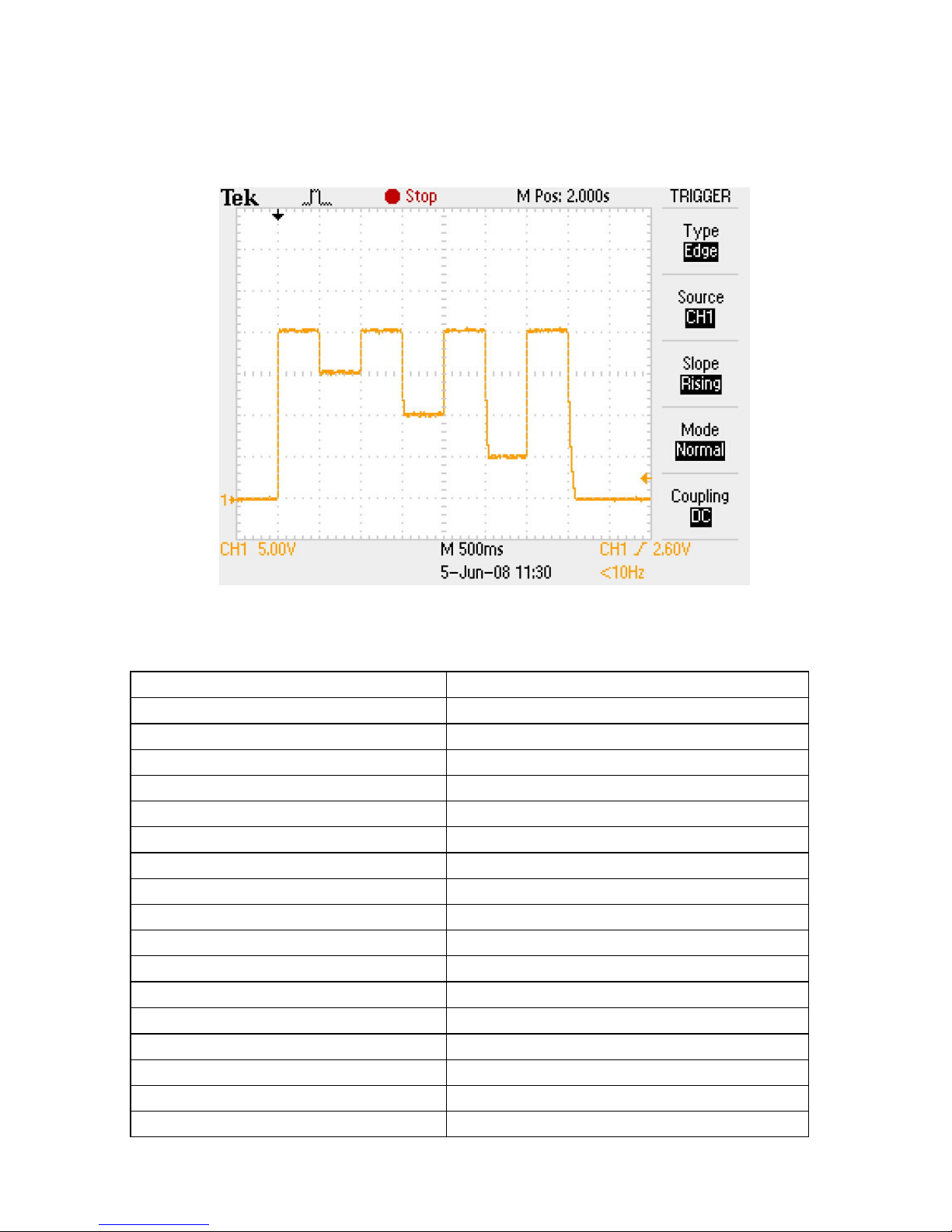
Example 2:
To output the wave form shown above, the following example program can
be used.
PROG 2
Choose program number
PROG:CLE
Clear program 2 data
PROG:REP 0
No r
epeat
after running this program
PROG:TOTA 8
Set program
2 to have
8 steps in total
PROG:STEP 1
Settings for
step 1
PRO
G:STEP:CURR 2
Set
output
current to 2 amperes
PROG:STEP:VOLT 20
Set
output
voltage to 20 volts
PROG:STEP:ONT 0.5
Set output
ON
time to
0.5 sec PROG:STEP 2
Choose step 2
PROG:STEP:CURR 2
PROG:STEP:VOLT 15
PROG:STEP:ONT 0.5
PROG:STEP 3
Settings for step 3
PROG:STEP:CURR 2
PROG:STEP:VOLT 20
PROG:STEP:ONT 0.5
PROG:STEP 4
Choose step 4
PROG:STEP:CURR 2
Page 58
49
PRO
G:STEP:VOLT 10
PROG:STEP:ONT 0.5
PROG:STEP 5
Choose step 5
PROG:STEP:CURR 1
PROG:STEP:VOLT 20
PROG:STEP:ONT 0.5
PROG:STEP 6
Choose step 6
PROG:STEP:CURR 2
PROG:STEP:VOLT 5
PROG:STEP:ONT 0.5
PROG:STEP 7
Choose step 7
PROG:STEP:CURR 2
PR
OG:STEP:VOLT 20
PROG:STEP:ONT 0.5
PROG:STEP 8
Choose step 8
PROG:STEP:CURR 2
PROG:STEP:VOLT 0
PROG:STEP:ONT 0.5
PROG:NEXT 0
Select next
program
to run after
program 2 is complete
, 0
means
stop
PROG:SAV
After edit, use
S
ave
command to store
program 2 in the hardware
PROG
2
PROG:RUN ON
T
o run the program stored in the
hardware, it shall select program
number and then use RUN ON
command to execute the program.
Page 59
50
Example 3:
If it needs to execute Program 2 right after Program 1 is executed then
program 1 shall be modified to have NEXT 2 command. The following steps
can be taken for the modification and execute the programs.
PROG 1 Select program 1
PROG:NEXT 2 Change the NEXT command from
NEXT 0 to NEXT 2
PROG:SAV After edit is complete use Save
command to store changes in the
hardware
PROG 1
PROG:RUN ON
To run the program by selecting the
program number first and then using
RUN ON command to execute it.
Page 60
51
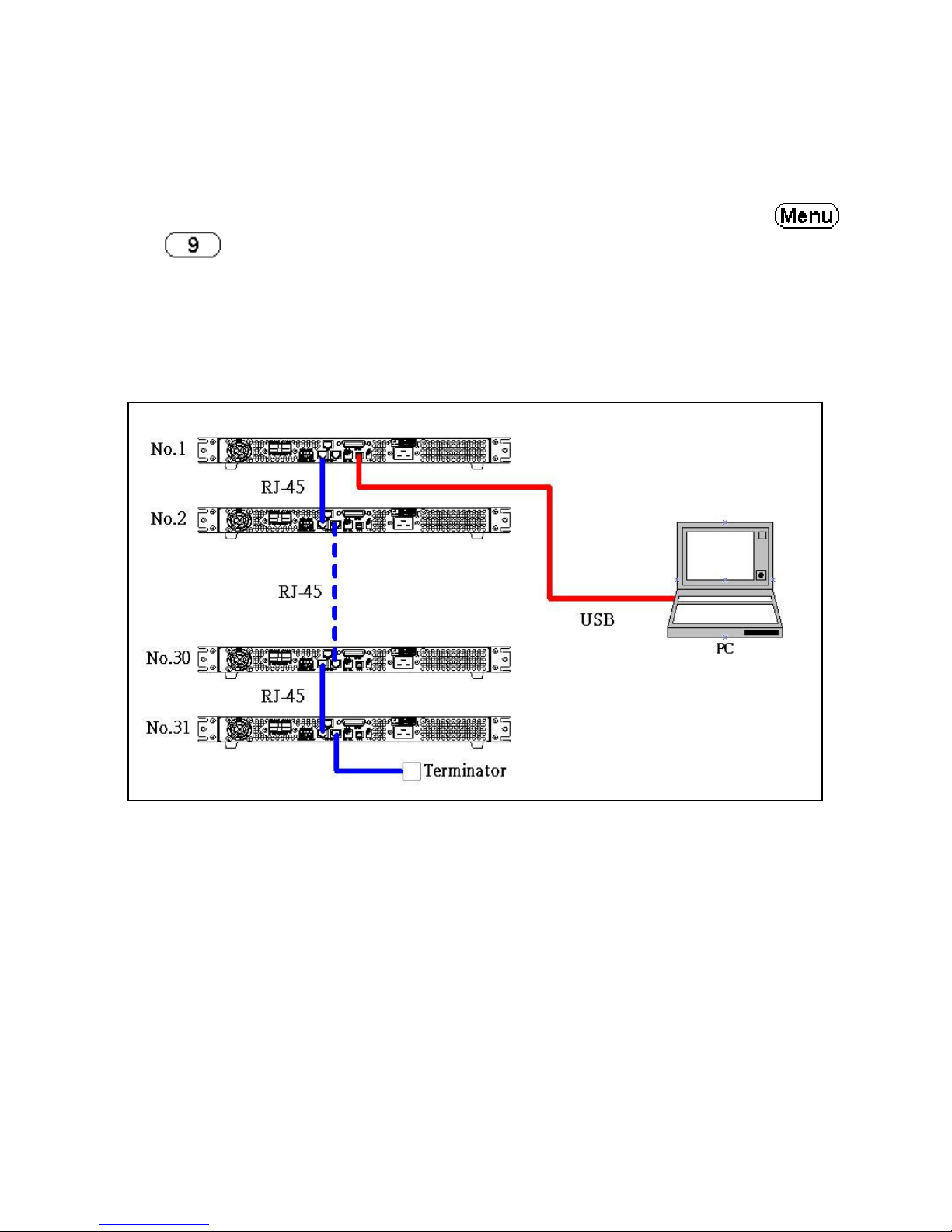
5.12 Series Connection Function (RS485)
DS3640/DS6024/DS8018/DS10014 can use RS485 to provide
multi-units series connection function for up to 31 units (If more than 10
units, please add the resistance 120
et CHAIN ON/OFF as ON (Series/Parallel
connection will be cancelled) and set each unit with the distinct Address (1 ~
31). Then by using USB to connect PC to any unit, multiple units can be
controlled by using the commands in Sec. 5.12.1 SERIES CONNECTION
COMMAND LIST.
5.12.1 Series Connection Command List
The series connection command used by all DS series through ASCII
string and must add the ending character (0x0A) behind the string. The
system will respond after every data delivers. For example, the system will
respond with the corresponding value or string when delivering the inquire
command, or respond “ OK” when delivering the setting command. In case
any errors happen, the system will respond what kind of error it is. (Please
refer to Sec. 5.12.2 ERROR RESPONSE LIST). Command table is as
below.
Page 61

52
SYSTEM CONTROL COMMAND
Command Description
==================================================
CADR followed by address, which can be 1 to 31 and
is used to access the power supply
CCLS Clear status
CRST Reset command. Brings the power supply to a
known state
CIDN? Returns the power supply model identification
CREV? Returns the firmware version
CSN? Returns the serial number
CST? Returns the device status
CCLR? Clear protect
==================================================
OUTPUT CONTROL COMMAND
Command Description
==================================================
CPV Sets the output voltage value in Volts
CPV? Reads the output voltage setting
CMV? Reads the actual output voltage
CPC Sets the output current value in Amperes
CPC? Reads the output current setting
CMC Reads the actual output current
CDVC? Display voltage and current data
COUT Turns the output to ON or OFF
COUT? Returns the output On/Off status
COV Sets the OVP level
COV? Returns the OVP setting level
COVP Sets the OVP on/off
COVP? Returns the OVP on/off
COC Sets the OCP level
COC? Returns the OCP setting level
Page 62

53
COCP Sets the OCP on/off
COCP? Returns the OCP on/off
COP Sets the OPP level
COP? Returns the OPP setting level
COPP Sets the OPP on/off
COPP? Returns the OPP on/off
CMODE? Returns the power supply operation mode
==================================================
SYNCHRONOUS CONTROL COMMAND
Command Description
==================================================
GRST Reset command. Brings the power supply to a
known state
GCLS Clear status
GCLR Clear protect
GPV Sets the output voltage value in Volts
GPC Sets the output current value in Amperes
GOUT Turns the output to ON or OFF
GOV Sets the OVP level
GOVP Sets the OVP on/off
GOC Sets the OCP level
GOCP Sets the OCP on/off
GOP Sets the OPP level
GOPP Sets the OPP on/off
==================================================
EXAMPLES
Q1. How to read back ID for Address 5 on the system?
CADR 5 OK
CIDN? Motech inc. DS 3640,A1234567,1.13,0
Q2. How to set up Voltage for Address 7 on the system?
CADR 7 OK
CPV 20 OK
Page 63

54
Q3. How to set up Output for Address 7 on the system?
CADR 3 OK
COUT 1 OK
Q4. How to read back Voltage value for Address 1 on the system?
CADR 1 OK
CMV? 10.001
Q5. How to set up Current for all the systems?
GPC 5 No response
Q6. How to set up Output for all the systems?
GOUT 1 No response
5.12.2 Error Response List
If PC delivers an error command or connection fails, the response string
will be shown as below.
String Description
===============================================
OK No error
Time out Wait response time out
Range error Input value is out of range
Multi master There are more than one controller in the whole
system
Page 64
55
6. Protections and Error Messages
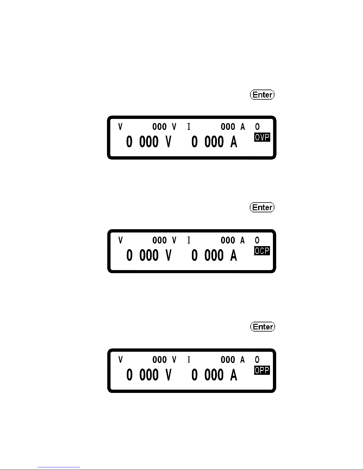
6.1 Over-voltage Protection (OVP)
When the OVP is activated and voltage measured is over the setting point of
protected voltage, system will enter the “ Over Voltage Protect” mode that will
shut off the output and show OVP on the display. Press to reset the
protection mode and deactivate buzzer.
= 36 .
.
= .40
.
FF
6.2 Over-current Protection (OCP)
When the OCP is activated and current measured is over the setting point of
protected current, system will enter the “ Over Current Protect” mode that will
shut off the output and show OCP on the display. Press to reset the
protection mode and deactivate buzzer.
.63=
.
10 .=
.
FF
6.3 Overpower Protection (OPP)
When the OPP is activated and power measured is over the setting point of
protected power, system will enter the “ Over Power Protect” mode that will
shut off the output and display OPP on the screen. Press to reset the
protection mode and deactivate buzzer.
.63=
.
10.=
.
FF
Page 65
56
6.4 Constant Voltage Protection (CV TO CC)
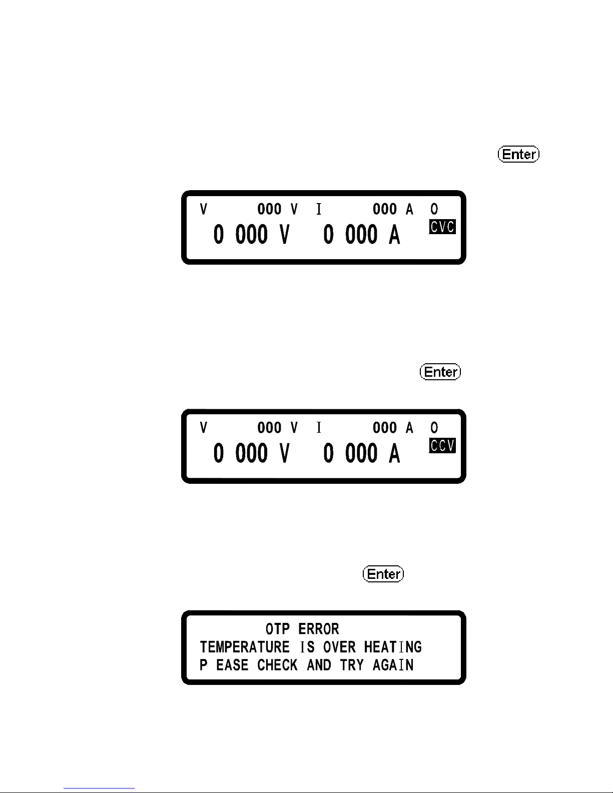
When this function is activated DS3640/DS6024/DS8018/DS10014 will stay in
CV mode. If load changes and forces the system turning from CV to CC
(constant current) mode, system will enter the “ CV TO CC Protect” that will
shut off the output and display the CVC message on the screen. Press
to reset the protection and deactivate buzzer.
10 .=
.
FF.63=
.
6.5 Constant Current Protection (CC TO CV)
When this function is activated DS3640/DS6024/DS8018/DS10014 will stay in
the CC mode. If load forces the measurement turn from CC to CV (constant
voltage) mode, system will enter the “ CC TO CV Protect” that will shut off
output and display CCV message on the screen. Press to reset the
protection and deactivate buzzer.
= 36 .
.
= .
0
1
.
FF
6.6 Over-temperature Protection (OTP)
When machine has detected abnormally high temperature, system will enter the
“ Over Temperature Protect” mode that will shut off output and display the erro
message as shown in the following figure. Press to reset the protection
and deactivate buzzer.
L
!!!!
.
Page 66
57
6.7 Low Voltage Protection (ACD)
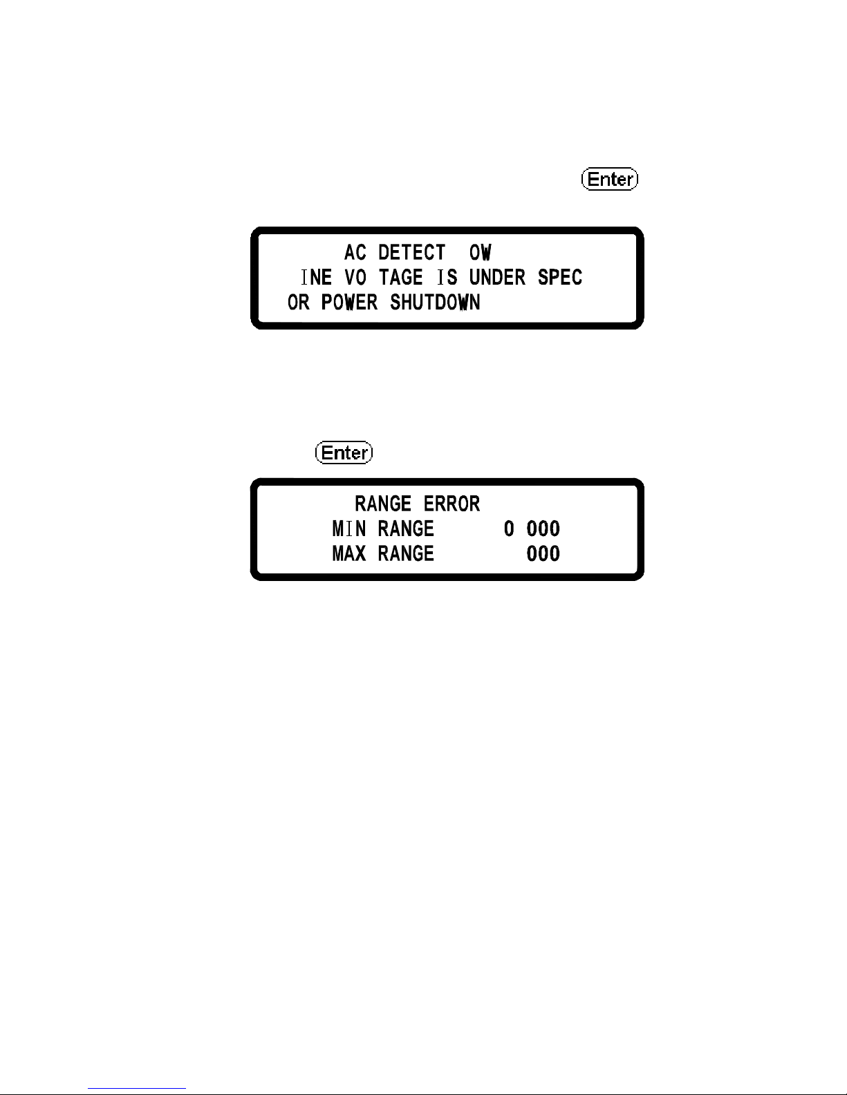
When the machine has detected abnormally low AC power input, system will
enter the “ AC Detect Low Protect” mode that will shut off output and display
the error message shown in the following figure. Press to reset the
protection and deactivate buzzer.
L ! ! ! !
.
.
LL
6.8 Error Input Message
When users enter a voltage or current setting that is beyond the acceptable
range, system will display “ RANGE ERROR” in response and show users the
correct input range. Press to re-enter the voltage/current setting.
!!!!
:
:
.
63 .
Page 67

58
7. Remote Interface communication protocol
The communication protocol includes the MOTECH commands and SCPI
commands.
7.1 Prefaces
The SCPI interface enables users to operate DS3640/DS6024/DS8018/
DS10014 through a computer or terminal that has IEEE-488.2 GPIB or USB
interface equipped. And it allows carrying out remote control and monitoring.
SCPI IEEE-488.2 version supports multi units control capability that allows a
user to control up to 32 DS3640/DS6024/DS8018/DS10014 units.
7.2 Parameters Definition
Type
Valid Arguments
<boolean > " ON" or 1, " OFF" or 0
<NR1 > The data format <NR1> is defined in IEEE-488.2 for
integers. Zero, positive and negative integer numeric
values are valid data.
<NRf >
The data format <NRf> is defined in IEEE-
488.2 for
flexible Numer
ic Representation. Zero, positive and
negative floating-point numeric values a
re some
examples of valid data.
<string > Characters enclosed by single or double quotes
<NL > New line, Hex code is 0x0Ah
<Rtn > Return, Hex code is 0x0Dh
<END > End or identify
Note: All commands shall be ended with the <Rtn> and <NL>. And there
shall be a space between the command and the parameter. For example,
to set the GPIB address of 10 to a DS3640/DS6024/DS8018/DS10014.
The command line is as follows:
ADDR 10<Rtn><NL >
Note: The<NL> and<Rtn> are not presented in the following examples and
command descriptions. However, users shall add them to the end of
each command when doing the coding.
Page 68

59
7.3 The Error/Event List
SCPI interface can offer an error/event list that contains up to 10 errors/events.
We can read the errors/events through the “error?” command in a first-in
first-out manner. Once an error/event is read, the read process will clean it from
the memory. To clean all errors/events from the memory, the “ *CLS”
command can be used.
Error
Description
-000 No error
-001 Command error
-002 Execution error
-003 Query error
-004 Input Range error
-005 Parallel/Series function, Error mode
-006 Parallel/Series function, Multi-Master
-007 Parallel/Series function, No Slave found
-008 Parallel/Series function, Communication with Slave A
error
-009 Parallel/Series function, Communication with Slave B
error
-010 Parallel/Series function, Communication with Slave C
error
-011 Parallel/Series function, Sync. signal error when
output on
-012 Parallel/Series function, Sync. signal error when
output off
Page 69

60
7.4 Compatible Protocol of MOTECH LPS & PPS Product Family
Command Description
ADDRess set the address of the machine
ADDRess? return the address of the machine
BEEP set beep on(1) or off(0)
CLR clear protect status
CURRent set current
CURRent? return current setting
ERRor? return error message
IOUT? current readback
ISET set current
ISET? return current setting
LOCK set rotary and keypad lock on(1) or off(0)
MODEL? return model name
OCP set current protect to off(0) or on(1)
OISET set overcurrent protect level
OISET? return overcurrent value
OPP set power protect to off(0) or on(1)
OPSET set overpower protect level
OPSET? Return overpower value
OUT set output on(1) or off(0)
OVP set voltage protect to off(0) or on(1)
OVSET set overvoltage protect level
OVSET? return overvoltage value
STATUS? return status of the machine
VERsion? return version number
VOLTage set voltage
VOLTage? return voltage setting
VOUT? voltage readback
VSET Set up output voltage
VSET? return voltage setting
Page 70

61
Examples:
Q 1:How to set GPIB address?
ADDR 10 ==>address is 10
Q 2:How to read back GPIB address?
ADDR? ==>return GPIB address
ADDRESS? ==>return GPIB address
Q 3:How to set up buzzer?
BEEP 1 ==>trigger beep to on
BEEP off ==>trigger beep to off
Q 4:How to clear the protecting state?
CLR ==>clear protect status
Q 5:How to read back to error information?
ERR? ==>return error code
Q 6:How to set up voltage?
VSET 10 ==>set voltage to 10V
VOLT 3.3V ==>set voltage to 3.3V
VOLTAGE 45 ==>set voltage to 45V (for DS6024)
Q 7:How to read the voltage setting value?
VSET? ==>return voltage setting
VOLT? ==>return voltage setting
VOLTAGE? ==>return voltage setting
Q 8:How to set up current?
ISET 1.1 ==>set current to 1.1A
CURR 4.3022 ==>set current to 4.3022A
CURRENT 0.250 ==>set current to 250mA
Q 9:How to read the setting value of current?
ISET? ==>return current setting
CURR? ==>return current setting
CURRENT? ==>return current setting
Q 10:How to read the voltage outputting value?
VOUT? ==>return voltage output
Page 71

62
Q 11:How to read the current outputting value?
IOUT? ==>return current output
Q 12:How to lock buttons and the knob controller?
LOCK 1 ==>lock the keypad and knob
LOCK ON ==>lock the keypad and knob
Q 13:How to read the product model number?
MODEL? ==>return machine model name
Q 14:How to set up OVP function?
OVP 1 ==>enable OVP protect
OVP OFF ==>disable OVP protect
Q 15:How to set up OVP voltage value?
OVSET 38 ==>set OVP level to 38 V
Q 16:How to set up OCP function?
OCP 1 ==>enable OCP protect
OCP OFF ==>disable OCP protect
Q 17:How to set up OCP electric current value?
OISET 40 ==>set OCP level to 40 A
Q18:How to set up OPP function?
OPP 1 ==>enable OPP protect
OPP OFF ==>disable OPP protect
Q 19:How to set up OPP power value?
OPSET 1000 ==>set OPP level to 1000 W
Q 20:How to set up output?
OUT 1 ==>output on
OUT OFF ==>output off
Q 21:How to read state value?
STATUS? ==>return status value
Q 22:How to read the firmware version?
VER? ==>return version information
VERSION? ==>return version information
Page 72

63
7.5 SCPI Conformable Information
SCPI is entirely compatible with all IEEE-488.2 and SCPI commands (1995).
Commands are included in SCPI commands (in Vol. 2, 1995).
7.5.1 Common SCPI commands
Command Explanation
*CLS Clear status (include error code)
*IDN? Response:<Manufacturer>, <model>, <serial number>,
<firmware type, & version >
*RCL Recalls settings from memory. Memory numbers from 0
to 9 are valid.
*RST Resets the power supply to its power on state.
*SAV 1. Saves defined parameters
2. Saves current settings to memory. Memory numbers
from 0 to 9 are valid.
Examples:
Q 23:How to store the voltage/current settings to memory devices?
*SAV 5 ==>save current settings to memory location 5
Q 24:How to recall the voltage/current settings from memory devices?
*RCL 3 ==>recall setting from memory location 3
Q 25:How to set up software reset?
*RST
Q 26:How to identify the instrument’s model number?
*IDN?
Q 27:How to clear error message?
*CLS
Page 73

64
7.5.2 SCPI Command subsystem
ABORt
Abort the Output Action
FETCh Fetch Subsystem
:CURRent? Return the fetched output current
:VOLTage? Return the fetched output voltage
MEASure Measure subsystem
:CURRent? Return the measured output current
:VOLTage? Return the measured output voltage
MEMory Memory Subsystem
<NR1 | ? > select or return memory number, range
from 0 ~ 9
:VSET <NRf | ? > set or return voltage:0~36V/0~60V
:ISET <NRf | ? > set or return current:0~40A/0~24A
:SAVE store memory subsystem parameters
OUTput Output Subsystem
<Boolean > enable or disable output action
? return output state
:LIMit
:VOLTage <NRf | ? > set or return voltage limit value
:CURRent <NRf | ? > set or return current limit value
:STATe? Return output mode (CV or CC)
:PROTection
:CLEar Reset latched protection
PROGram Program Subsystem
<NR1 | ? > select or return memory number, range
from 1 ~ 10
Page 74

65
:CLEar clear program n parameters
:ALL clear all program parameters
:NEXT <NR1 | ? > ser or return next prog
ram number (1 ~
10 , 0 for end)
:REPeat <NR1 | ? > set or return repeat times (max.
50000)
:RUN<Boolean | ? > set or query program on/off state
:SAV save program parameters
:STEP < Boolean | ? > set or return step number
:CURRent <NRf | ? > set or return step n current setting
:ONTimet <NRf | ? > set or return step n output time (0.050
~ 20000S)
:VOLTage <NRf | ? > set or return step n voltage setting
:TOTA[l] <NR1 | ? > set or return program n total step
numbers (max. 150)
PROTection Protection Subsystem
? return protect state
:CCCV <Boolean | ? > set or return CC to CV protect state
:CLEar Resets latched protection
:CVCC <Boolean | ? > set or return CV to CC protect state
:OCP <Boolean | ? > set or return over-current protect state
:LEVel <NRf | ? > set or return over-current protect value
:OPP <Boolean | ? > set or return over-power protect state
:LEVel <NRf | ? > set or return over-power protect value
:OVP <Boolean | ? > set or return over-voltage protect state
:LEVel <NRF | ? > set or return over-voltage protect value
PS Parallel/Series Subsystem
:MODE <OFF/0,PARALLEL/1,SERIES/2|? >
Page 75

66
set or return parallel/series mode
:TYPE <MASTER/0,SLAVEA/1,SLAVEB/2,SLAVEC/3|?>
set or return master/slave setting
[SOURce] Source Subsystem
:CURRent <NRf | ? > set or return current level:0~40/0~24A
:PROTection <Boolean | ? >
set or return over-current state
:LEVel <NRf | ? > set or return over-current level
:VOLTage <NRf | ? > set or return voltage level:0~36/0~60V
:PROTection <Boolean | ? >
set or return over-voltage state
:LEVel <NRf | ? >
set or return over-voltage level
SYStem System Subsystem
:BEEP <Boolean | ? > set or return BEEP state
:E5V <Boolean | ? > enable or disable extra 5V output
:ERRor? return system error
:EXTernal<OFF/0,VOLT/1,RES/2 | ? >
set or return external state
:GPIB
:ADDRess <NR1 | ? > set or return GPIB address (1~31)
:IP
:ADDRess <NR1.NR1.NR1.NR1 | ? >
set or return IP address
:CONFig <STATic/0,DHCP/1 | ? >
set or return IP config mode
:KEY
:LOCK <Boolean | ? set or return key lock state
Page 76

67
:LCD
:BL <Boolean | ? > set or return LCD backlight state
:POWer
:CURRent <NRf | ? > set or return user define current level
:STATe <Boolean | ? > set or return user define output state
:TYPE <OFF/0,LAST/1,USER/2 | ? >
set or return power up mode
:VOLTage <NRf | ? > set or return user define voltage level
:RECall
:DEFault recall factory default setting
:REMote <USB/0,GPIB/1,ETHERNET/2 | ? >
set or return remote interface
:SERies? Return series number
TIMER Timer Subsystem
<Boolean > enable or disable timer mode
? return timer state
:HOUR<NR1 | ? > set or return timer hours
:MINute<NR1 | ? > set or return timer minutes
:SECond<NR1 | ? > set or return timer seconds
Page 77

68
Examples:
Q 28:How to cancel all actions?
ABOR
ABORT
Q 29:How to fetch current value?
FETC:CURR?
FETCH:CURRENT?
Q 30:How to fetch voltage value?
FETC:VOLT?
FETCH:VOLTAGE?
Q 31:How to measure current?
MEAS:CURR?
MEASURE:CURRENT?
Q 32:How to measure voltage?
MEAS:VOLT?
MEASURE:VOLTAGE?
Q 33:How to set up and read back the specific memory set?
MEM 1
MEMORY 3
MEM?
MEMORY?
Q 34:How to set up and read back the voltage stored in specific memory
set?
MEM:VSET 10
MEM:VSET?
MEMORY:VSET 20
MEMORY:VSET?
Q 35:How to set up and read back the current stored in specific memory
set?
MEM:ISET 15
MEM:ISET?
MEMORY:ISET 25
Page 78

69
MEMORY:ISET?
Q 36:How to save data to memory set?
MEM:SAVE
MEMORY:SAVE
Q 37:How to set up and cancel output?
OUT ON
OUTPUT 0
Q 38:How to set up and read back the voltage limit?
OUT:LIM:VOLT 30
OUT:LIM:VOLT?
OUTPUT:LIMIT:VOLTAGE 35
OUTPUT:LIMIT:VOLTAGE?
Q 39:How to set up and read back the current limit?
OUT:LIM:CURR 30
OUT:LIM:CURR?
OUTPUT:LIMIT:CURRENT 35
OUTPUT:LIMIT:CURRENT?
Q 40:How to set up and read back the voltage SLEW RATE?
OUT:SR:VOLT 2.4
OUT:SR:VOLT?
OUTPUT:SR:VOLTAGE 0.01
OUTPUT:SR:VOLTAGE?
Q 41:How to set up and read back the current SLEW RATE?
OUT:SR:CURR 2.5
OUT:SR:CURR?
OUTPUT:SR:CURRENT 0.01
OUTPUT:SR:CURRENT?
Q 42:How to read back the output state?
OUT:STAT?
OUTPUT:STATE?
Q 43:How to read back the protection state?
PROT?
Page 79

70
PROTECTION?
Q 44:How to set up and read back the CC to CV protection state?
PROT:CCCV ON
PROT:CCCV?
PROTECTION:CCCV 0
PROTECTION:CCCV?
Q 45:How to set up and read back the CV to CC protection state?
PROT:CVCC ON
PROT:CVCC?
PROTECTION:CVCC 0
PROTECTION:CVCC?
Q 46:How to clear the state of protection?
PROT:CLE
PROTECTION:CLEAR
OUT:PROT:CLE
OUTPUT:PROTECTION:CLEAR
Q 47:How to set up and read back the overcurrent protection state?
PROT:OCP ON
PROT:OCP?
PROTECTION:OCP 0
PROTECTION:OCP?
SOUR:CURR:PROT ON
SOUR:CURR:PROT?
SOURCE:CURRENT:PROTECTION 0
SOURCE:CURRENT:PROTECTION?
Q 48:How to set up and read back the overcurrent protection point?
PROT:OCP:LEV 30
PROT:OCP:LEV?
PROTECTION:OCP:LEVEL 40
PROTECTION:OCP:LEVEL?
SOUR:CURR:PROT:LEV 25
SOUR:CURR:PROT:LEV?
SOURCE:CURRENT:PROTECTION:LEVEL 35
SOURCE:CURRENT:PROTECTION:LEVEL?
Page 80

71
Q 49:How to set up and read back the overpower protection state?
PROT:OPP ON
PROT:OPP?
PROTECTION:OPP 0
PROTECTION:OPP?
Q 50:How to set up and read back the overpower protection point?
PROT:OPP:LEV 30
PROT:OPP:LEV?
PROTECTION:OPP:LEVEL 40
PROTECTION:OPP:LEVEL?
Q 51:How to set up and read back the overvoltage protection state?
PROT:OVP ON
PROT:OVP?
PROTECTION:OVP 0
PROTECTION:OVP?
SOUR:VOLT:PROT ON
SOUR:VOLT:PROT?
SOURCE:VOLTAGE:PROTECTION 0
SOURCE:VOLTAGE:PROTECTION ?
Q 52:How to set up and read back the overvoltage protection point?
PROT:OVP:LEV 30
PROT:OVP:LEV?
PROTECTION:OVP:LEVEL 40
PROTECTION:OVP:LEVEL?
SOUR:VOLT:PROT:LEV 25
SOUR:VOLT:PROT:LEV?
SOURCE:VOLTAGE:PROTECTION:LEVEL 35
SOURCE:VOLTAGE:PROTECTION:LEVEL?
Q 53:How to set up the buzzer?
SYS:BEEP ON
SYSTEM:BEEP 0
Q 54:How to set up the extra 5V voltage output?
SYS:E5V ON
SYSTEM:E5V 0
Page 81

72
Q 55:How to read back error code?
SYS:ERR?
SYSTEM:ERROR?
Q 56:How to set up and read back the external adjustment state?
SYS:EXT VOLT
SYS:EXT?
SYSTEM:EXTERNAL RESISTANCE
SYSTEM:EXTERNAL?
Q 57:How to set up and read back the GPIB address?
SYS:GPIB:ADDR 5
SYS:GPIB:ADDR?
SYSTEM:GPIB:ADDRESS 6
SYSTEM:GPIB:ADDRESS?
Q 58:How to set up and read back the IP address?
SYS:IP:ADDR 192.168.0.208
SYS:IP:ADDR?
SYSTEM:IP:ADDRESS 192.168.10.10
SYSTEM:IP:ADDRESS?
Q 59:How to set up and read back the IP mode?
SYS:IP:CONF DHCP
SYS:IP:CONF?
SYSTEM:IP:CONFIG STATIC
SYSTEM:IP:CONFIG?
Q 60:How to set up and read back the key locking?
SYS:KEY:LOCK ON
SYSTEM:KEY:LOCK?
Q 61:How to set up and read back the LCD backlighting function?
SYS:LCD:BL ON
SYSTEM:LCD:BL?
Q 62:How to set up and read back the booting mode?
SYS:POW:TYPE LAST
SYS:POW:TYPE?
SYS:POWER:TYPE USER
Page 82

73
SYS:POWER:TYPE?
SYSTEM:GPIB:ADDRESS?
Q 63:How to set up and read back the voltage under user-defined booting
mode?
SYS:POW:VOLT 10
SYS:POW:VOLT?
SYSTEM:POWER:VOLTAGE 20
SYSTEM:POWER:VOLTAGE?
Q 64:How to set up and read back the current under user-defined booting
mode?
SYS:POW:CURR 10
SYS:POW:CURR?
SYSTEM:POWER:CURRENT 20
SYSTEM:POWER:CURRENT?
Q 65:How to set up and read back the output state under user-defined
booting mode?
SYS:POW:STAT ON
SYS:POW:STAT?
SYSTEM:POWER:STATE 0
SYSTEM:POWER:STATE?
Q 66:How to recall back default setting?
SYS:REC:DEF
SYSTEM:RECALL:DEFAULT
Q 67:How to set up and read back the communication interface?
SYS:REM GPIB
SYS:REM?
SYSTEM:REMOTE ETHERNET
SYSTEM:REMOTE?
Q 68:How to read back the SERIES NUMBER?
SYS:SER?
SYSTEM:SERIES?
Q 69:How to set up and read back the output voltage?
SOUR:VOLT 30
Page 83

74
SOUR:VOLT?
SOURCE:VOLTAGE 35
SOURCE:VOLTAGE?
Q 70:How to set up and read back the output current?
SOUR:CURR 40
SOUR:CURR?
SOURCE:CURRENT 35
SOURCE:CURRENT?
Q 71:How to set up and read back parallel/series mode?
PS:MODE PARALLEL
PS:MODE?
PS:MODE 2
PS:MODE OFF
Q 72:How to set up and read back master/slave in parallel/series mode?
PS:TYPE MASTER
PS:MODE?
PS:MODE SLAVEB
PS:MODE 3
Q 73:How to set up Program function?
Refer to Sec 5.11 (Programmable capability).
Page 84
75
7.6 State Bit Definition
When “STATE?” command is used, the system will return three (3) bytes in
the order as shown below.
Byte 2 Byte 1 Byte 0
bit 7 ~ bit 0 bit 7 ~ bit 0 bit 7 ~ bit 0
The definition of each bit is described in the following table.
byte 0: bit 7 OVP on/off status
bit 6 OCP on/off status
bit 5 OPP on/off status
bit 4 CC to CV on/off status
bit 3 CV to CC on/off status
bit 2 output on/off status
bit 1 LCD back light on/off status
bit 0 External 5V output on/off status
byte 1: bit 7 OVP occur flag
bit 6 OCP occur flag
bit 5 OPP occur flag
bit 4 CC to CV occur flag
bit 3 CV to CC occur flag
bit 2 AC dectect low occur flag
bit 1 OTP occur flag
bit 0 reserved
byte 2: bit 7 ~ 0 reserved
7.7 LAN Communction
All DS series provide three LAN control modes, including Web
server, Telnet and Sockets. First, enter the first Item “ System Setting”
on the menu to set the interface selection (Remote Control) as Ethernet,
and select IP setting procedure as Static or use DHCP (Dynamic Host
Configuration Protocol). If using static IP, it needs to set up IP address.
After completed, it will be able to use the above LAN control mode
to control the DS series.
Page 85
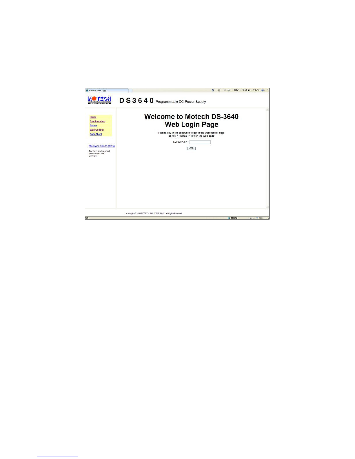
76
7.7.1 Using Web Server
All DS series have built-in Web Server. User can control the DS series
on the computer by using the Web browser. Open Web browser and
input IP address to enter Welcome page.
Enter password (presetted as 123456) to login the main page (Home),
and then click to select the Items on the left side to the other settings or
control page.
7.7.1.1 Main Page (Home)
The main page shows all the basic message and network information.
Page 86
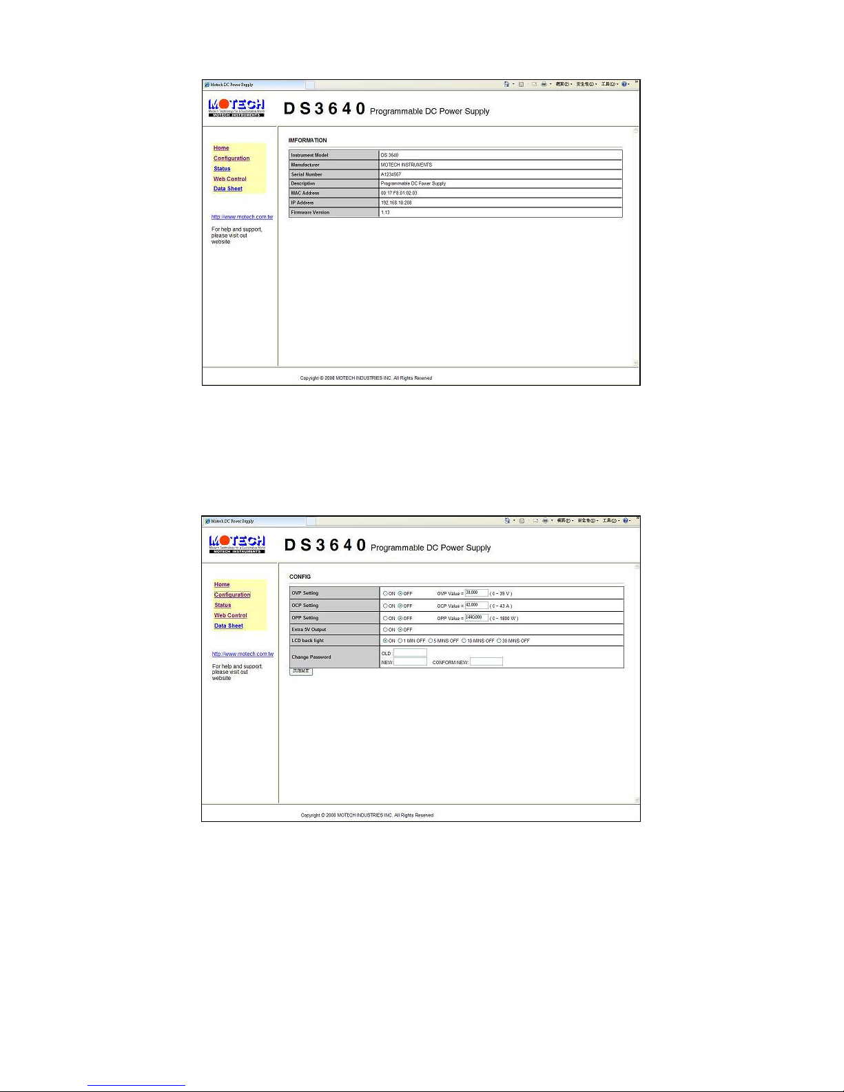
77
7.7.1.2 Setting Page (Configuration)
7.7.1.3 Status of Page (Status)
Display the status of the system. In case of any error codes, please refer
to Sec. 7.3 Error/Event list
Page 87
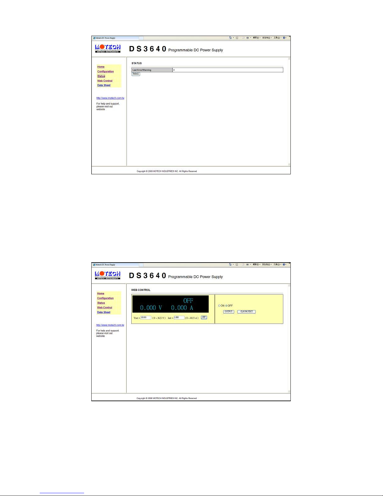
78
7.7.1.4 Web Control
Set up voltage/current and output. In addition, monitoring the
output voltage/current value on line is also allowed (JAVA
support is required.).
7.7.2 Using Telnet
Enter behind the command prompt under MS-DOSTelnet DeviceIP 5024
(IP address of the system is Device IP 5024 is as Telnet port) will into
Page 88
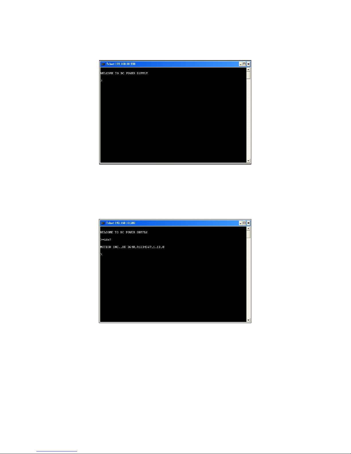
79
Welcome page shown as below
Input SCPI command behind the command prompt to communicate with
the system.
7.7.3 Using Sockets
All DS series using port 5025 to provide the standard function of SCPI
socket. Users can give SCPI command to achieve the purpose of
controlling the systems through users’ program by using the standard
SCPI socket.
Page 89
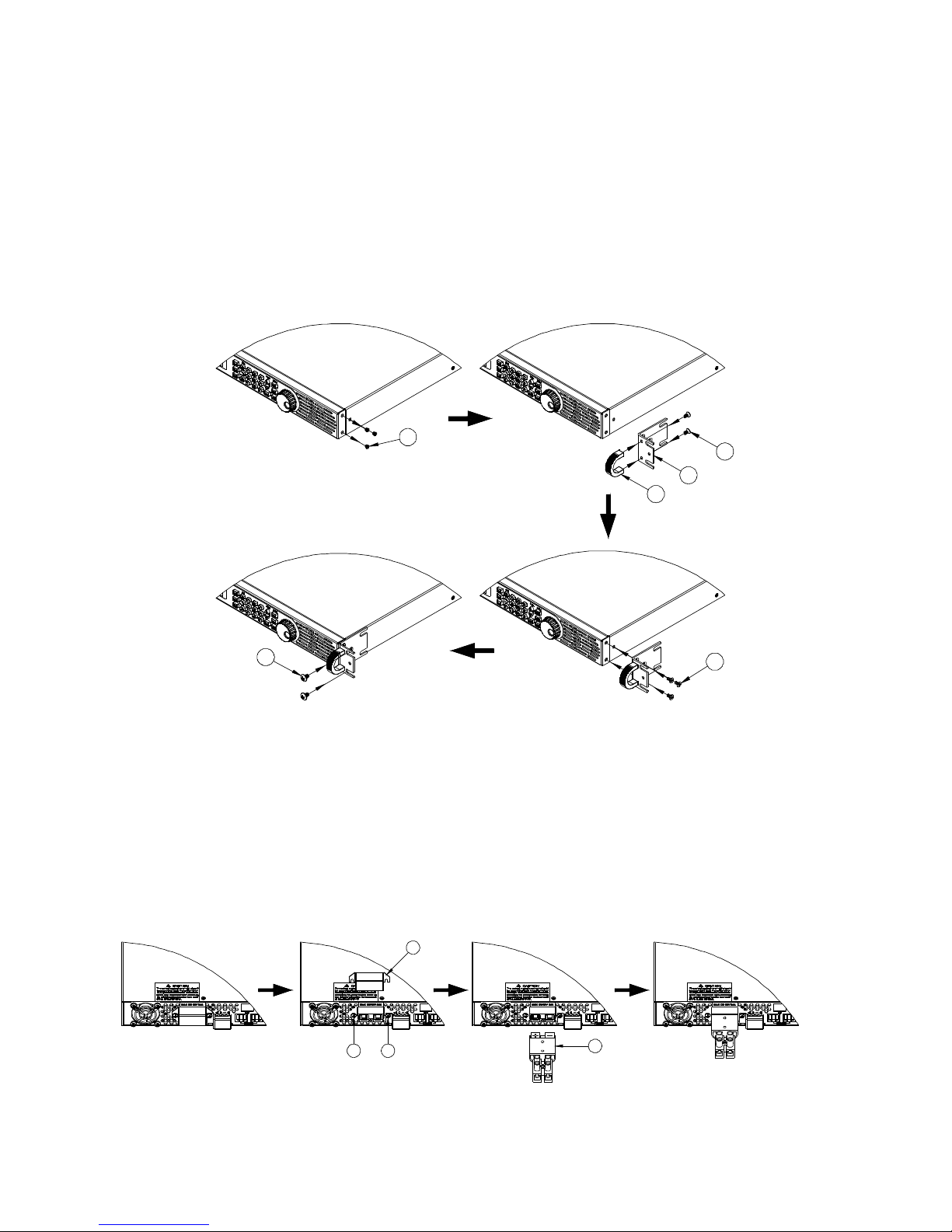
80
8. Assemble Accessories
8.1 Assemble Rack Mount Brackets
The DS3640/DS6024/DS8018/DS10014 is designed to fit in a space of one
rack unit (1U) and can be mounted in a standard 19-inch rack panel or cabinet.
Rack mount brackets shall be assembled before mount in a rack. Refer to the
following figure to assemble the rack mount brackets.
Step 1
Step 3
6
2
3
4
5
Step 2
Step 4
1
8.2 Assembly of Output Protective Shield (DS6024/DS8018/DS10014)
Safety regulation requests protective shield when the output voltage is higher
than 45Vdc. Therefore, there are protective shields for the output connectors
for the DS6024/DS8018/DS10014. Refer to the following figure for the
assembly/disassembly of the output protective shield.
Step 2
2
1
Step 1
1
3
Step 3
8.3 Assembly of Remote Sense Protective Shield
Page 90
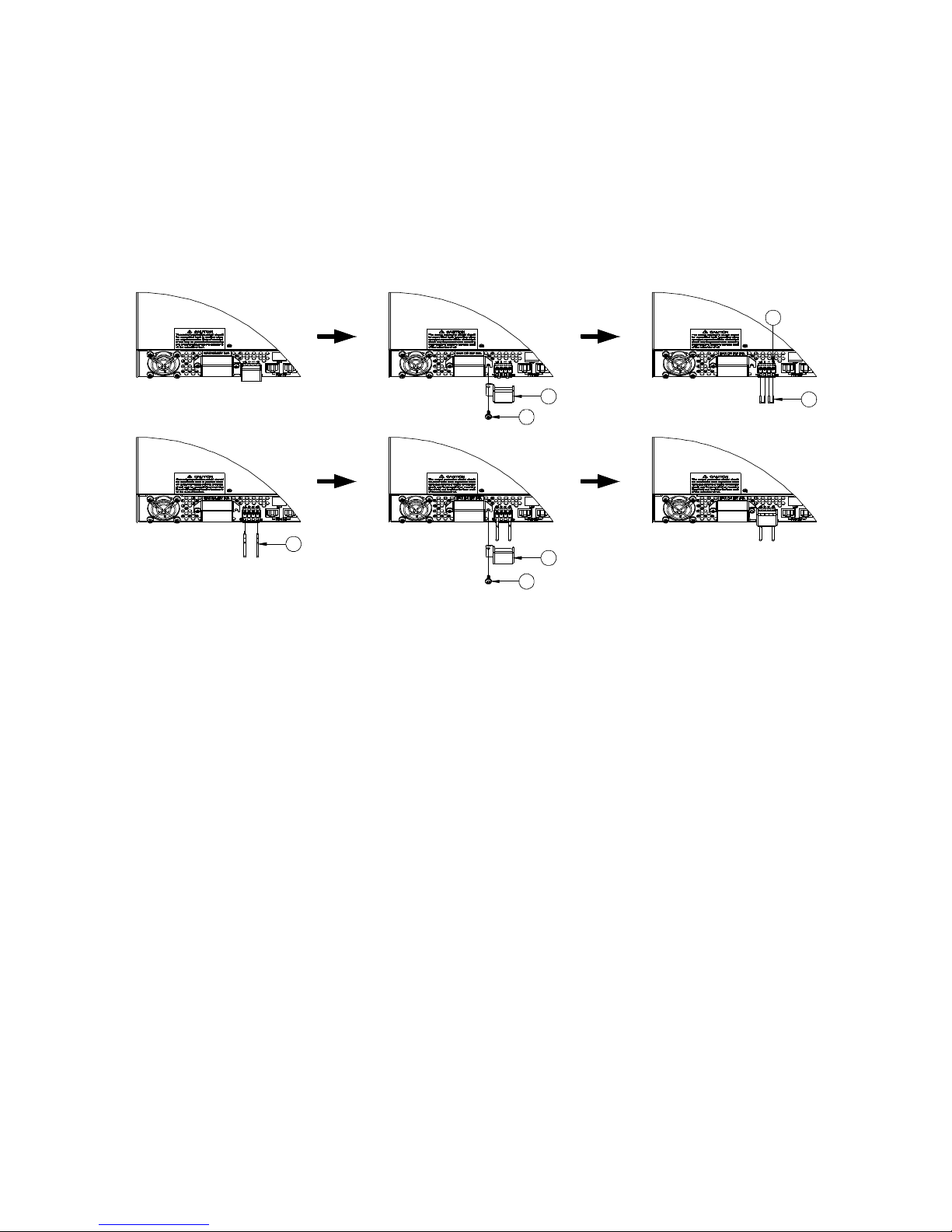
81
(DS6024/DS8018/DS10014)
Safety regulation requests protective shield when the voltage is higher than
45Vdc. Therefore, there are protective shields for the remote sense connectors
for the DS6024/DS8018/DS10014. Refer to the following figure for the
assembly/disassembly of the remote sense protective shield.
3
4
Step 4
5
Step 1
1
2
Step 5
Step 2
7
6
Step 3
Page 91

82
9. Accessories
Product Name:DS3640/DS6024/DS8018/DS10014
Parts List:
Item
Name & Specification Qty Remarks
1. Terminal Block for Rapid Plug
Connector
1
2. Fixing sheet (slice) 2
3. Hand-holding bar 2
4. Operation Manual 1
5. Power Cord 1
6. Screw(M4x8) 10
7. Screw(M5x8) 4
8. Guarantee certificate 1
WARNING:
All parts of this product are safety-
certified that can satisfy wide
applications under the specified specification. Users
should thoroughly
read over this Manual and follow the instruction
s to use them. For
example, when changing side fasteners, users
should pay attention on
the correct information regarding the order, screw amount and
respective lengths, etc., to ensure for a co
rrect installation rather than
making any mistake in assembly that would jeopardize user’s rights
and interests of warranty service.
Editing Version:Ver 1.0
Page 92

Page 93

Page 94

ZOMG-3640ME-2
 Loading...