

Page 1

MoTeC SDL User Manual
Contents
Introduction ........................................................................ 1
Overview ............................................................................. 2
Display ................................................................................................................ 2
Alarms ................................................................................................................. 5
Data Logging ...................................................................................................... 5
Other Functions .................................................................................................. 7
Measurement Inputs ........................................................................................... 8
Auxiliary Outputs .................................................................... ............... ............ 12
Communications Overview ............................................................................... 13
ECU Connection ............................................................................................... 13
Lap Beacon ....................................................................................................... 14
Options ............................................................................................................. 14
Software ............................................................................................................ 14
Updateable Firmware ........................................................................................ 15
Installation ........................................................................ 17
Mounting ........................................................................................................... 17
Display Care ..................................................................................................... 18
Wiring ................................................................................................................ 18
External Buttons ............................................................................................... 19
External Lights .................................................................................................. 20
Thermocouples ................................................................................................. 20
Connecting to a MoTeC ECU ............................................... .................. ............ 20
Sport Dash Manager Software ........................................ 23
Introduction ....................................................................................................... 23
Computer Requirements ................................................................................... 23
Installing Sport Dash Manager .......................................................................... 24
Mouse & Keyboard ........................................................................................... 24
Main Menu .......................... .................. ................................. ............... ............ 24
Toolbar .............................................................................................................. 25
On line / Off line ................................................................................................ 25
Configuration .................................................................................................... 26
Configuration Files ............................................................................................ 26
Changing the Configuration .............................................................................. 27
Versions and Updating ...................................................................................... 28
Channels ........................................................................................................... 29
Conditions Overview ......................................................................................... 33
Checking Operation .......................................................................................... 34
Sensor Zeroing ................................................................................................. 35
Details Editor .................................................................................................... 35
Page 2

Windows Keyboard Use .................................................. 37
Main Menu .......................... .................. ................................. ............... ............ 37
Closing a Window ....... ...................................................... ................. ............... 37
Getting Help ...................................................................................................... 37
Selecting an Item in a Window .......................................................................... 38
Using the Selected Item .................................................................................... 38
Appendices ....................................................................... 42
Appendix A: General Specifications .................................................................. 42
Appendix B: Options Summary ......................................................................... 43
Appendix C: Sport Dash Manager Command Line ........................................... 44
Appendix D: Input Characteristics ..................................................................... 46
Appendix E: Auxiliary Output Characteristics .................................................... 52
Appendix F: CAN Bus Specification .................................................................. 53
Appendix G: ECU to SDL Wiring (RS232) ........................................................ 54
Appendix H: CAN Wiring ................................................................................... 56
Appendix J: USB Wiring .................................................................................... 57
Appendix K: Typical Wiring (with BR2).............................................................. 58
Appendix L: Pin List by Function ....................................................................... 59
Appendix M: Pin List by Pin Number ................................................................. 61
Appendix N: Connector ..................................................................................... 62
Appendix P: Wire Specifications ....................................................................... 63
Appendix Q: Case Dimensions .............................................. ............... ............ 64
© Copyright – Motec Pty Ltd – 2008
The information in this document is subject to change without notice.
While every effort is taken to ensure correctness, no responsibility will be taken for the consequences of any
inaccuracies or omissions in this manual.
Version 1.1, 21 October 2008
Page 3

MoTeC Introduction 1
Introduction
Thank you for purchasing a MoTeC SDL Dash / Logger.
SDL
The MoTeC SDL Dash / Logger is a combined LCD dash unit and high
performance data logger. Note that a ‘display only’ version of the SDL is also
available
This Manual Covers:
• Overview of the SDL capabilities
• Installation
• Overview of the MoTeC SDL and Sport Dash Manager software
Software Information
For detailed information on using the various software programs refer to the
online help supplied with the program.
Other Manuals
Separate Manuals are available for:
• MoTeC Lap Beacon / BR2
• Interpreter Data Analysis Software
Sensor Details
Drawings are available for all MoTeC sensors and can be found on the
MoTeC Resource CD (included with the SDL) or on the MoTeC website at
www.motec.com.au
requirements for each sensor.
. The drawings detail the mounting and wiring
Page 4
2 Overview
Overview
Display
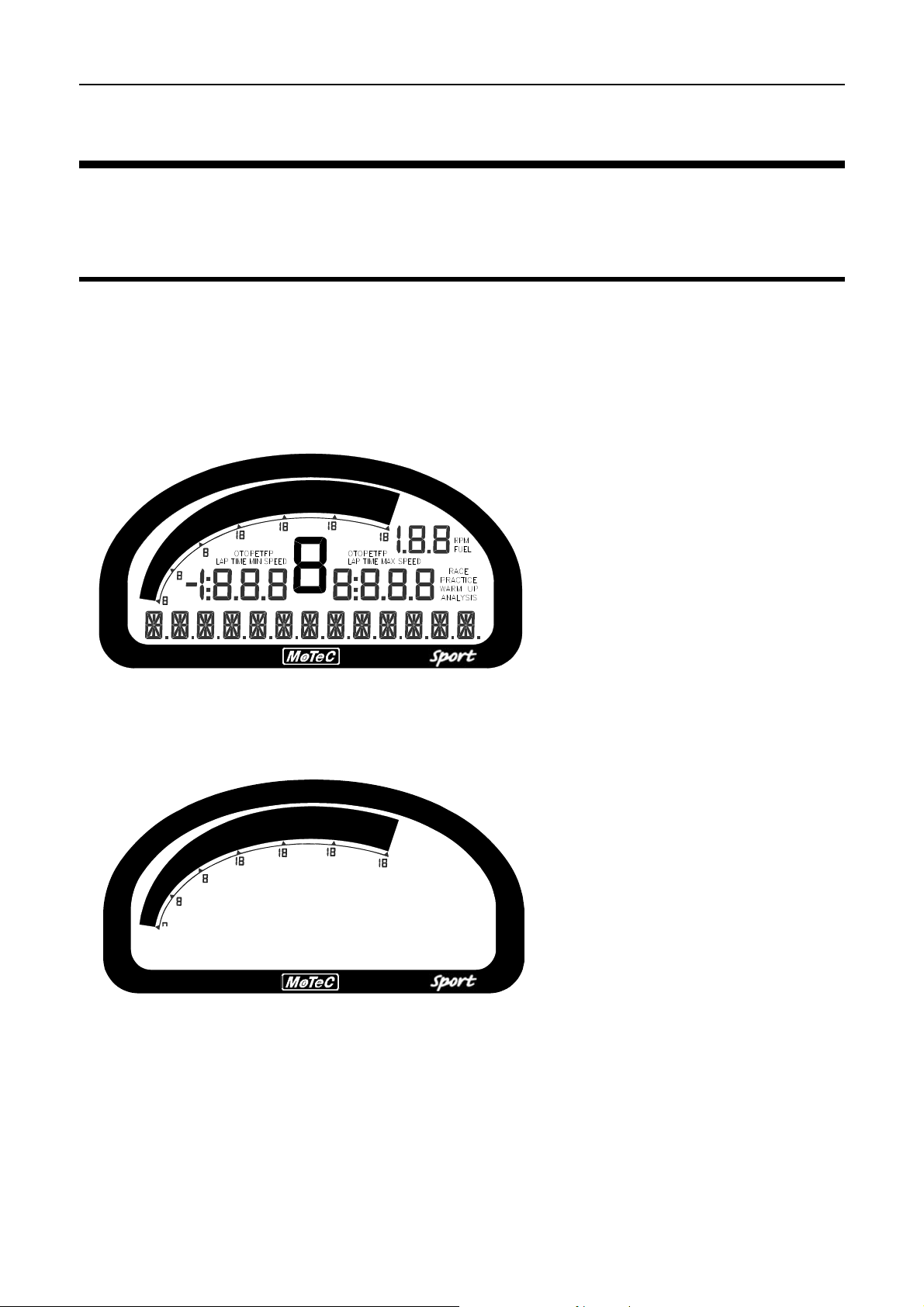
The SDL display is a high contrast, high temperature, custom made LCD
display.
The display contains a Bar Graph, three Numeric Displays, a Centre Numeric
Display and a Bottom Alpha / Numeric Display.
Bar Graph
The 70 segment bar graph has a user definable range and is typically used as
a tacho, however it can be used to display any other value. When used as a
tacho it may be configured for up to 19,000 RPM.
A programmable shift point can be displayed.
Page 5
MoTeC Overview 3
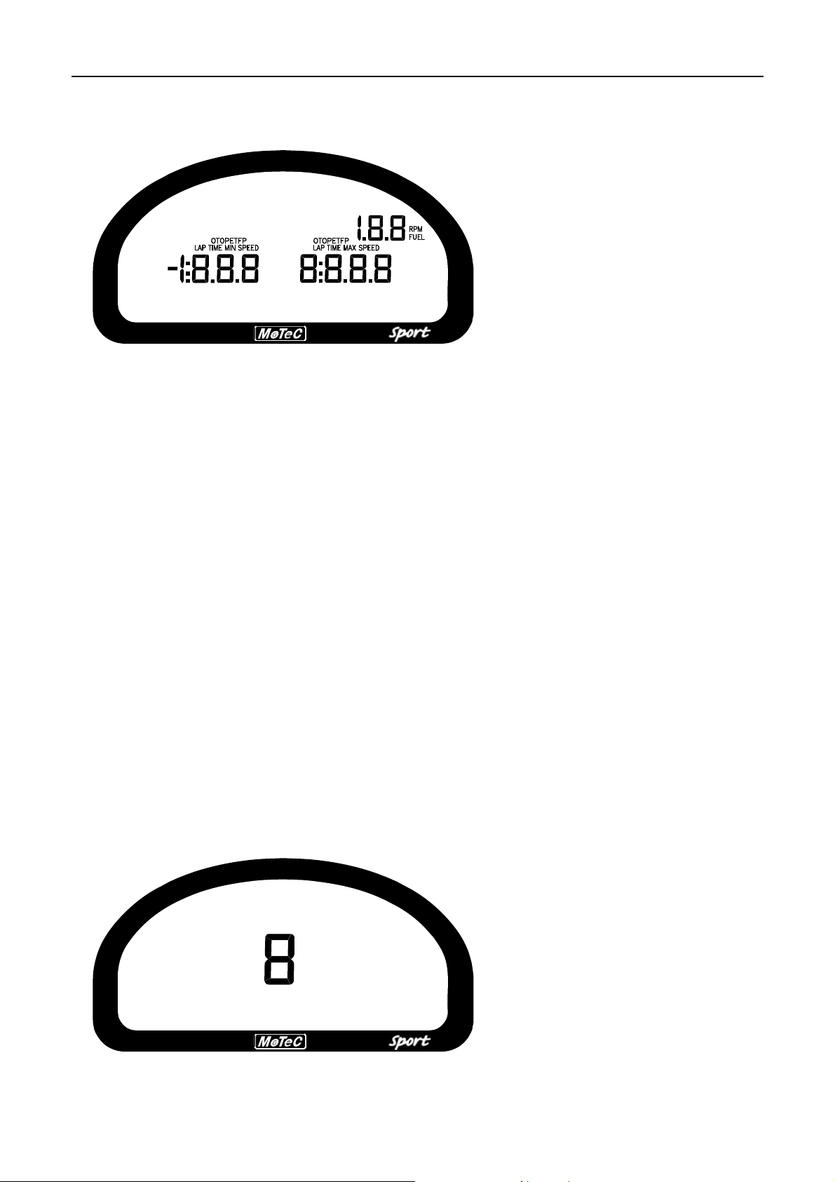
Numeric Displays
The three numeric displays (Left, Right and Top Right) can be programmed to
display any value.
Note that each of the three numeric displays has a different number of digits
and are therefore suited to displaying different values. For example the Top
Right display can only show values up to a maximum of 199 and is therefore
not suitable for displaying Lap Times, but is suitable for displaying many other
values such as Lap Number, Fuel Remaining, Engine Temperature etc.
The numeric displays can show any channel value plus an override value,
shown each time the value is updated. This is useful for values that are
updated periodically, for example Lap Time. The override values are shown
for a programmable period of time, for example a numeric display could
normally show the Running Lap Time (which is continuously updating) then
be overwritten by the Lap Time for 10 seconds each time the Lap Time is
updated.
Enunciators for some of t he common display values are provided above the
numeric displays, eg. ET (Engine Temperature), OP (Oil Pressure).
Centre Numeric Display
Page 6
4 Overview
The Centre Numeric display is incorporated to show the current gear but may
be used for other purposes.
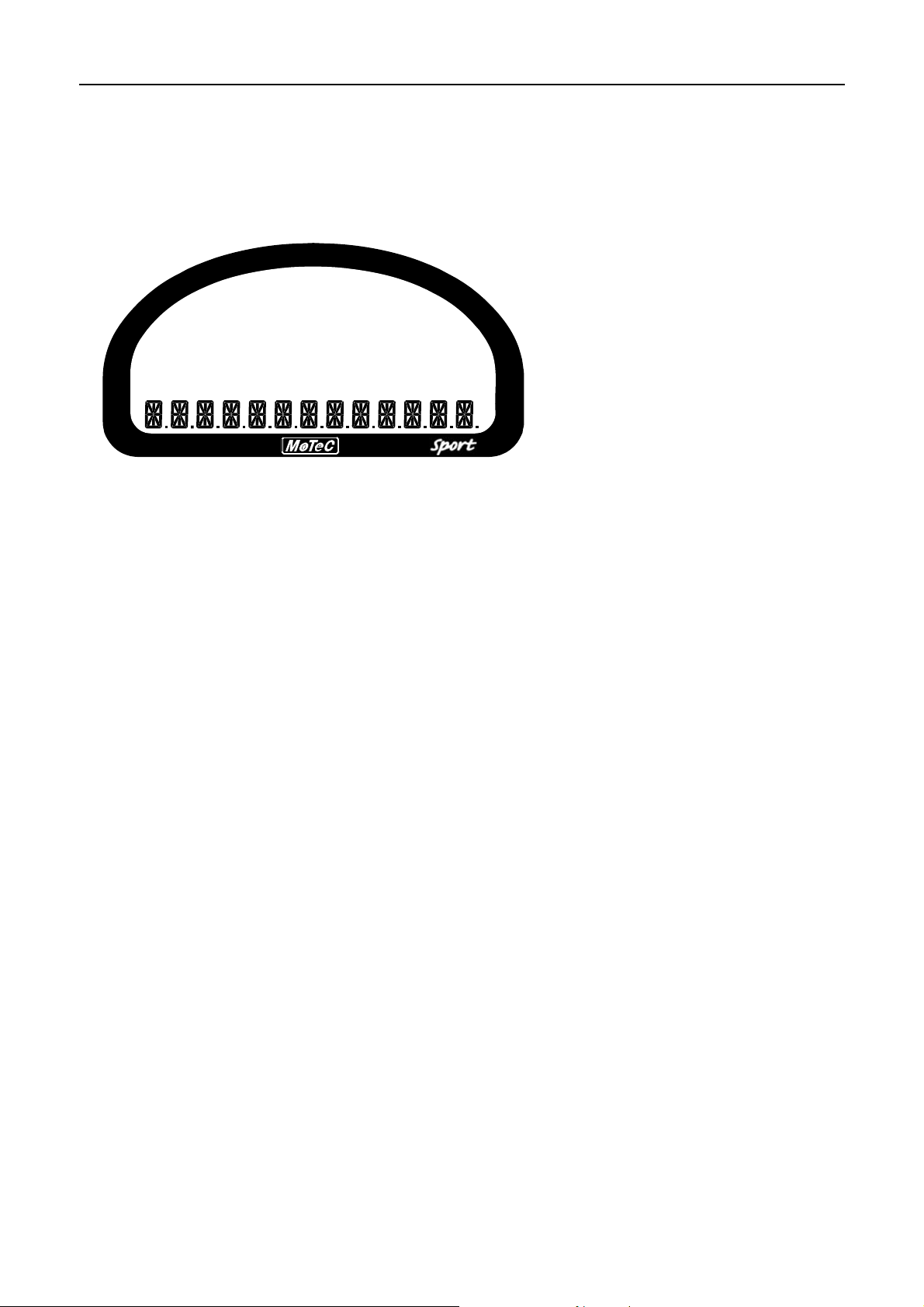
Bottom Display
The 13 digit alpha numeric display can display up to 10 lines of information
that can be scrolled up or down using the external buttons. Each of the 10
lines can display up to 3 channel values at a time.
Additionally the bottom display can show an override value, similar to the
numeric displays.
The bottom display will also show any active alarm messages, which will
override all other values until the alarm is cleared.
Display Formatting
Units
The display units can be changed to suit the driver, for example the driver
may prefer to see the engine temperature in Fahrenheit rather Celsius. This is
independent of the units used for other purposes.
Decimal Places
The number of decimal places can be reduced for display purposes, for
example the engine temperature is measured to 0.1 °C but is better displayed
with no decimal places. This is normally done automatically.
Page 7

MoTeC Overview 5
Alarms
When an alarm is activated a message is shown on the bottom line of the
display, a warning light can also be activated which is recommended to draw
the drivers attention to the display.
The message displayed can be defined and can also include the current
sensor reading or the sensor reading when the alarm was triggered.
The alarms remain active until they are acknowledged, either by a driver
activated switch or automatically after a defined period of time.
The warning alarm limits are fully programmable and may include up to 2
comparisons to ensure that the alarms are only activated at the correct time.
For example, an engine temperature alarm may activate at 95 °C if the
ground speed has been above 50 km/h for 30 seconds. The speed
comparison avoids the alarm showing during a pit stop due to heat soak.
Additionally another comparison could be set at a higher temperature to cover
all other situations.
Data Logging
Data logging allows the sensor readings (or any calculated value) to be stored
in the SDL for later analysis.
Logging Memory
The SDL comes with an optional 8Mbytes log memory enabled. It is also
possible to purchase a ‘display only’ SDL without the memory option enabled.
Data is logged continuously logs data to memory whenever the Start
Condition is true (and the Stop Condition is false).
Page 8

6 Overview
When the logging memory is full the SDL begins to overwrite the oldest data,
which ensures that the most recent data is always available. This is referred
to as cyclic logging.
Power
The SDL power can be turned off at any time without losing the logged data.
The SDL uses FLASH memory which does not require an internal battery to
keep it alive.
Logging Rate
The SDL can store any value at up to 200 times per second, which can be
individually set for each logged item.
The rate at which the values are logged is very important – the value must be
logged fast enough to record all variations in the reading. If the value is
logged too slowly then the readings can be totally meaningless. For example
suspension position normally needs to be logged at 100 times per second or
more.
Note, however, that if a value is logged faster than necessary it will not
improve the accuracy of the logged data, it will just reduce the total logging
time available. For example, the engine temperature only needs to be logged
at once per second.
Logging Time
The maximum logging time is dependent the number of items logged and the
rate at which they are logged. The configuration software will report the
logging time, taking these factors into account.
Logging Rates
The logging Rate may be individually set for each value between 1 to 200
times per second.
Start and Stop Logging Conditions
Two options are provided; the default is to log data while the engine is
running. The condition is to start when Engine RPM >= 200 rpm for 2
seconds. Logging will stop when Engine RPM < 200 rpm for 20 seconds. This
requires that the Engine RPM channel is present in the configuration.
The alternative is to specify start and stop logging conditions to suit the
application. For example logging might start when the vehicle exceeds 50
Page 9

MoTeC Overview 7
km/h, and stop when the engine RPM is below 500 RPM for 10 seconds. Note
that the Start Condition must be true and the Stop Condition must be false
before logging will start.
Retrieving the Logged Data
A laptop or desktop PC is used to unload the logged data from the SDL. The
logged data is then stored on the computer hard disk.
The logged data may be retrieved at very high speed (approximately 2.5
seconds per Mbyte when using USB or 20sec Mbyte when using CAN).
After each unload the user has the option to clear the logging memory.
The unload may be interrupted part way through if necessary by
disconnecting the computer. The partial unload will contain the most recently
logged data and will be stored on the computer hard disk. In this case the
SDL logging memory is not cleared and logging will continue as normal at the
end of the existing data. Next time the logged data is unloaded both the new
data and the previously partly unloaded data will be retrieved.
Track Map Sensor Requirements
In order for the logging analysis software to plot a track map the following
sensors are required and must be logged.
• Lateral G force (inbuilt in the SDL)
• Wheel Speed
• Lap Beacon (from either MoTeC Beacon kit or a switch. Note that the
‘Beacon’ Channel must be logged)
• Longitudinal G force (Optional: See Below)
A Longitudinal G force sensor should be used if the vehicle has only one
wheel speed sensor. This allows the analysis software to eliminate wheel
lockups which is essential when creating or using a track map.
Other Functions
The SDL can perform many other functions and calculations including the
following:
Page 10

8 Overview
Functions:
• Shift Lights – Controls up to 3 staged shift lights.
• Engine Log – Can be used to record engine running times during the
specified condition
Calculations:
The SDL can calculate and display any of the following:
• Lap Time, Running Lap Time, Lap Number.
• Ground Speed, Drive Speed, Lap Distance, Trip Distance, Odometer.
• Lap Time Gain / Loss continuously displays how far behind or ahead the
vehicle is compared to a reference lap.
• Current Gear.
• Minimum Corner Speed, Maximum Straight Speed.
• Fuel Used, Fuel Remaining.
• Two 2D and two 3D Lookup Tables
Measurement Inputs
The SDL measurement inputs can be connected to a wide variety of sensors.
This allows the SDL to measure vehicle parameters such as: Suspension
Movement, Wheels Speeds, Steering Angle, Engine Temperature etc.
Input Types
The SDL has a number of different input types which are designed to suit the
different types of sensors.
The following inputs are available:
• 8 Voltage Inputs
• 4 Temperature Inputs
• 1 Optional Wide Band Air Fuel Ratio Input (Lambda Input)
• 2 Switch Inputs
• 2 Digital Inputs
Page 11

MoTeC Overview 9
• 2 Wheel Speed
Expander Inputs
Additionally one E888 expander may be connected to read from 8 K-type
thermocouples.
Internal Sensors
The SDL also includes internal sensors for G-Force Lateral, G-Force Vertical,
Battery Voltage and SDL Internal Temperature.
Sensors
Different types of sensors are available to suit different types of
measurements.
Sensors convert a physical measurement (e.g. Pressure) into an electrical
signal (e.g. Volts). Different types of sensors generate different types of
electrical signals. For example most temperature sensors convert the
temperature into a variable resistance signal which may be measured by the
SDL Temperature inputs, however most wheel speed sensors generate a
variable frequency signal which must be connected to either a Digital input or
a Speed input.
Calibration
Calibration is the process of converting the electrical value, e.g. Volts into a
number that represents the physical value, e.g. Temperature.
All inputs can be calibrated to suit the connected sensor.
The calibrations can be selected from a number of predefined calibrations
provided by MoTeC, or they can be entered by the user.
Analog Voltage Inputs
The 8 Analog Voltage inputs are normally used to measure the signals from
analog voltage type sensors, i.e. sensors with variable voltage outputs, such
as:
• Rotary or linear potentiometers
• Signal conditioned 3 wire pressure sensors
• Thermocouple amplifiers
• Accelerometers
Page 12

10 Overview
These inputs can also be used to measure two wire variable resistance
sensors if an external pullup resistor is connected from the input to the 5V
sensor supply. Additionally, on/off switch signals may be connected, which
may also require an external pullup resistor.
Measurement Methods
These inputs can be configured to use several measurement methods to suit
the various types of sensors:
• Absolute Voltage: The sensor voltage is independent of the sensor supply
voltage
• Ratiometric Voltage: The sensor voltage is proportional to the 5V sensor
supply voltage
• Variable Resistance: The sensor resistance can be entered directly.
• On/Off : The voltage for on and off can be defined
Input Voltage Range
The measurable input voltage range is 0 to 5.5V on inputs AV1 to 4 and is 0
to 15 Volts on all other AV inputs.
Specifications
For full specifications see Appendix D: Input Characteristics.
Analog Temp Inputs
The 4 Analog Temp inputs are identical to the Analog Voltage inputs, except
that they contain a 1000 ohm resistor which is connected internally from the
input pin to the 5V sensor supply. This allows the Analog Temp inputs to be
used with two wire variable resistance sensors such as:
• Two wire thermistor temperature sensors
• Two wire variable resistance pressure sensors
Some voltage output sensors can also be used if they can drive the 1000 ohm
resistor without causing an error in their reading (eg MoTeC Thermocouple
Amplifier). Additionally, on/off switch signals may be connected.
Measurement Methods
These inputs use the same measurement methods as the Analog Voltage
Inputs.
Page 13

MoTeC Overview 11
Input Voltage Range
The measurable input voltage range is 0 to 15 Volts. This allows selection
from a wide range of sensors.
Specifications
For full specifications see Appendix D: Input Characteristics.
Wide Band Lambda Input
The single high accuracy, fully temperature compensated Wide Band Air Fuel
Ratio measurement input can be used if the Lambda Option is enabled.
This input connects directly to a MoTeC 4 wire Wide Band Lambda Sensor
and is accurate to 1.5% up to 1.2 Lambda under all load and temperature
conditions.
Note that this is the Bosch LSM sensor and not the 5 wire Bosch LSU sensor.
Note that NTK Lambda sensors should be connected to an Analog Voltage
input via the appropriate amplifier.
Switch Inputs
The 2 switch inputs are generally used for the external switches required to
operate the SDL display. They can also be connected to a brake switch or
other switch.
These inputs have a 4700 ohm resistor connected internally from the input pin
to the 5V sensor supply so that a switch can be simply connected between
the input pin and 0 volts.
Specifications
For full specifications see Appendix D: Input Characteristics.
Digital Inputs
The 2 digital inputs are identically to the switch inputs except that they include
the following additional measurement methods:
• Frequency: The frequency of the input signal is measured
• Period: The time between successive pulses is m ea sure d
• Pulse width: The low time of the pulse is measured
• Count: Counts the number of pulses
Page 14

12 Overview
Specifications
For full specifications see Appendix D: Input Characteristics.
Speed Inputs
The 2 Speed Inputs are identical to the Digital Inputs except that they can
also be configured to suit Variable Reluctance (Magnetic) sensors such as
some wheel speed sensors. Because the amplitude of the signal from these
sensors varies with speed of rotation, variable trigger levels are required,
which must vary with the frequency of the input signal.
The Speed Inputs can also be used with Hall Effect type wheel speed
sensors.
• Note also that the Pulse Width measurement method measures the high
time of the pulse rather than the low time as measured by the Digital
Inputs.
Specifications
For full specifications see the Appendices.
Internal Sensors
The SDL includes internal sensors for G force lateral, G force Vertical, battery
voltage and internal temperature.
Expander Thermocouple Inputs
An E888 expander may be connected to the SDL to read the 8 thermocouple
inputs. These are added and calibrated when the CAN comms template “E8xx
Rx EGT” is selected as one of the 6 possible CAN devices.
Auxiliary Outputs
The SDL has 4 Auxiliary Outputs which may be used to control various
vehicle functions such as: Gear Change Lights, Warning Lights, Thermatic
Fan, Gear Box Oil Pump, etc. The outputs are On/Off only and do not support
variable frequency or duty cycle control.
The Auxiliary Outputs switch to ground and can drive up to 0.5 Amps. Devices
that consume more than 0.5 Amps such as motors should be driven via a
relay.
Page 15

MoTeC Overview 13
Communications Overview
The SDL has various communications ports which are used to communicate
with other devices.
USB Communications Port
The USB communications port is used to communicate with a PC. See
Appendix J: USB Wiring for wiring details.
RS232 Communications Port
The RS232 communications port can be connected to an ECU, GPS or
similar device.
CAN Communications Port
The CAN (Control Area Network) communications port can be connected to
other devices with a compatible CAN port. The advantage of CAN is that
many devices can be connected to the CAN bus at once, which allows all
connected devices to communicate with each other, also the CAN port
communicates at very at high speed.
Other MoTeC products that use CAN for intercommunication include the
M800, BR2, PLM and MDD.
Note that these devices communicate at 1Mbit/sec, so any other devices
connected on the CAN bus must also communicate at 1Mbit/sec.
ECU Connection
The SDL can be connected to many Engine Management Systems (ECUs).
This avoids duplication of sensors and allows the SDL to display and log
many ECU parameters.
The ECU may send up to 40 values to the SDL. The update rate of these
values depends on how many values are transmitted, the communications
baud rate and if sent using CAN or RS232. For RS232 the typical update rate
is about 20 times per second and for CAN it is about 50 times per second.
Note that logging the ECU values faster than these rates is unnecessary and
will reduce the total logging time.
Page 16

14 Overview
• Note that if the SDL is connected to a MoTeC M800 ECU the M800
sensors should be calibrated in metric otherwise special scaling will be
required.
Lap Beacon
A Lap Beacon can be connected to the SDL in order to record Lap Times for
display and to provide lap reference information for the data logging analysis
software.
The MoTeC Lap Beacon consists of a Transmit ter which is m ount e d beside
the track and a Receiver which is mounted in the vehicle.
A switch can also be used to generate lap times, although this is significantly
less accurate than a l a p beacon system.
For further details refer to the Lap Beacon manual.
Options
Various options allow the SDL to be upgraded to perform additional functions,
specifically wide band lambda measurement and Pro Analysis.
The options can be enabled at any time by calling your MoTeC dealer,
purchasing the upgrade and then entering the upgrade password.
See Appendix B: Options Summary for details.
Software
The SDL comes with software packages for managing the SDL and analysing
the logged data. All software required is available on the CD provided, or can
be downloaded from the internet. Go to www.motec.com.au
links to “Software”.
and follow the
The software must be run on a laptop or desktop computer running Windows
98/2000/XP.
The following software programs are provided:
Page 17

MoTeC Overview 15
SDL Sport Dash Manager
MoTeC Sport Dash Manager is used for configuration, testing, retrieving the
logged data and for general management of the SDL.
An overview of Sport Dash Manager is included later in this manual.
Sport Dash Manager communica tes with the SDL via a USB cable. See
Appendix J: USB Wiring for wiring details.
Interpreter
Interpreter is used to analyse the logged data, this is covered in a separate
manual.
BR2Config
This program is used to configure the BR2 beacon receiver via a CAN
connection. BR2 configuration is covered in the BR2 Manual.
Updateable Firmware
The SDL control software (firmware) is field updatable so that new software
features can be used as they become available.
Page 18

Page 19

MoTeC Installation 17
Installation
Mounting
Mounting Dimensions
Refer to the product dimensions in the Appendices.
Attachment
Use washers between the unit and the mounting panel to ensure that the unit
is mounted only at the mounting points (to avoid twisting the case). The SDL
has three threaded mounting posts.
Do not over tighten the mounting screws (to avoid twisting the case).
Vibration isolation may be desirable if the vehicle vibrates severely.
Orientation
For best contrast, the display should be viewed at approx imately 20 degrees
above normal, however the SDL will give good contrast between 0 and 40
degrees. Display reflections should also be considered when determining the
mounting angle.
Note that for accurate readings from the inbuilt vertical G sensor the SDL
should be mounted as close to vertical as possible.
20°
Connector Access
Mount so that the connector may be easily accessed.
Page 20

18 Installation
Display Care
Take care when cleaning the display, use a soft cloth to avoid scratching the
display and avoid aggressive solvents.
Wiring
Pin Connection Details
The SDL pin connection list appears at the back of this manual.
Wire
Use 22# Tefzel wire (Mil Spec M22759/16-22) (5 amps max at 100 °C)
Note that the Tefzel wire is difficult to strip unless the correct stripping tool is
used. Be careful not to nick the wires as this may result in wire failure or poor
crimping.
Some sensor connectors may not be available with 22# terminals, in which
case doubling the wire over gives the equivalent of an 18# wire, which is
suitable for many of the common sensor terminals.
For full wire specifications see Appendix P: Wire Specifications.
Connector
The SDL uses a 37 pin Auto Sport connector, see Appendix N: Connector for
full details.
To ensure that the connector is sealed plug unused holes with filler plugs. A
heat shrink boot may also be used if desired.
Crimping
Ensure that the correct crimping tool is used for all contacts to ensure a
reliable connection.
The correct mil spec crimping to ol must be used for the SDL crimp pins. See
Appendix N: Connector for details.
• Note that the Crimp Contacts are type 22D which is needed to set the
crimp tool correctly.
Page 21

MoTeC Installation 19
Power Wiring
Power the SDL via a separate switch and a 5 Amp fuse. The separate switch
is recommended so that the computer can communicate with the SDL without
needing to turn the rest of the vehicle power on.
Ground Wiring
Ground the SDL to a good ground. The ground should have a direct
connection to the vehicle battery.
USB Wiring
See Appendix J: USB Wiring for USB wiring details.
CAN Bus Wiring
Refer to Appendix H: CAN Wiring for details.
Sensor Wiring
MoTeC can supply wiring details for all sensors.
External Buttons
A number of external buttons are required for various functions of the SDL.
Typically these buttons are used for:
• Display Next Line
• Alarm Acknowledge
• Lap Number Reset
• Fuel Used Reset (can also be done by holding the alarm acknowledge
button for 2 seconds)
These buttons are normally wired to the SDL Switch Input pins, but may also
be wired to the Digital or Analog Inputs, if the Switch Inputs are occupied.
Note that it is possible to configure the ADL to use the Alarm Acknowledge
button to reset the Lap Number and Fuel Remaining by holding it for a period
of time. This reduces the number of buttons required.
The buttons should be wired between an SDL input and SDL 0V pins.
Page 22

20 Installation
Note that if wired to an Analog Voltage input an external pull-up resistor must
be connected between the input pin and the 5V sensor supply.
External Lights
All lights including the Shift Lights & Warning Lights must be wired externally.
This allows a choice of lights and allows the lights to be placed in the optimum
position.
The MoTeC Shift Light Module (SLM) can be used for this purpose, otherwise
LEDs or LED arrays can be used.
SLM
The SLM includes 8 LEDs that can be programmed to any colour and can be
used for both warning lights and multiple shift lights plus many other
functions.
The SLM is connected to the SDL via the CAN bus so it does not occupy any
of the auxiliary outputs.
LEDs
LEDs may be wired to any of the four Auxiliary Outputs.
The LEDs must be wired between one of the Auxiliary Outputs and battery
positive and must include a current limiting resistor.
Thermocouples
Thermocouples must be wired to the SDL via a thermocouple amplifier.
The MoTeC Thermocouple Amplifier (TCA) may be used with K Type
thermocouples and may be connected to either the Analog Voltage or Analog
Temperature inputs of the SDL.
Connecting to a MoTeC ECU
An ECU may be connected to the SDL which will make information in the
ECU available to the SDL for display or logging or any other purpose.
MoTeC M400/M600/M800/M880 ECUs may be connected via CAN or via
RS232.
Page 23

MoTeC Installation 21
The MoTeC M4, M48 & M8 ECUs must be connected via RS232.
Connection via RS232
The telemetry feature of the MoTeC ECU is used to send data to the SDL via
an RS232 connection.
See Appendix G: ECU to SDL Wiring (RS232) for wiring details.
ECU Setup
The ECU ‘Telemetry Set’ and ‘Telemetry Baud Rate’ should be selected to
suit an RS232 communications template supported by the SDL.
SDL Setup
Setup for the SDL is done in the ‘Inputs | Communications’ setup screen.
Select a communications template that matches the ECU type and ECU
telemetry set.
In the displayed channel list, check those channels that you wish to receive in
the SDL
Interruption of the Data
Note that when using RS232, the data flow to the SDL will be interrupted
while a computer is connected to the ECU and will not resume for up to 10
seconds after the computer has been unplugged. During this period any value
that comes from the ECU, such as RPM or Engine Temperature will not be
updated and will normally be displayed as zero. On later versions of the ECU
software the 10 second delay is reduced to 1 second.
Connection via CAN
The SDL and ECU must be connected on the same CAN bus.
See Appendix H: CAN Wiring for wiring details.
ECU Setup
Set the ‘CAN Data Set’ to a set supported by the SDL (normally set 1).
The ‘CAN Address’ must also be set. Normal value for SDL is 1520. This is a
decimal value that corresponds to a hexadecimal value of 0x5F0 in the SDL.
Page 24

22 Installation
SDL Setup
Setup for the SDL is done in the ‘Inputs | Communications’ setup screen.
Select a communications template that matches the ECU type and ECU set.
In the displayed channel list, check those channels that you wish to receive in
the SDL.
ECU Sensor Calibrations
Metric Calibration of the sensors should be used in the ECU otherwise special
scaling is required in the SDL communications setup.
Page 25

MoTeC Sport Dash Manager Software 23
Sport Dash Manager Software
Introduction
The following is an overview of the main concepts of the Sport Dash Manager
software. More detailed information is available from the online help provided
with Sport Dash Manager. Online help is not currently available (Version
1.1.0.49) but will be available at a later stage.
The Sport Dash Manager software is used for:
• Editing the configuration files
• Sending configuration files to the SDL
• Retrieving the logged data from the SDL
• Testing the SDL
• Enabling SDL options
• Upgrading the SDL software version
• Changing event, venue and vehicle details
Computer Requirements
The Personal Computer (PC) must be an IBM PC compatible running
Windows 98/2000/XP.
Recommended Minimum Specifications
Pentium III, 64Mb RAM, USB1.0 or Parallel Port
USB Port or Printer Port
The PC must have a USB1.0 or compatible USB port or a Printer port.
The USB port is the recommended connection method because it is much
faster however if necessary a MoTeC CAN Cable may be used instead which
should be connected to the printer port.
Page 26

24 Sport Dash Manager Software
Installing Sport Dash Manager
From a CD-ROM
Place the CD-ROM into the CD drive of the pc.
A new window will appear. This can be navigated in the same way as a web
page.
If it does not appear, click on the Windows Start button and select Run. Type
‘D:\index.htm’
Click on the button marked ‘Software Archive’.
Select the version of Sport Dash Manager (or other software) that you wish to
install and click on the name.
When the dialog appears asking you to ‘Open’ or ‘Save’ the selected file,
choose ‘Open’ and then follow the setup program instructions.
From the Internet
Go to the MoTeC web site at www.motec.com.au and select Software
Updates then Current Release Software. Click on one of the SDL Sport Dash
Manager link to start the down load and choose to save the file to a location
where it can be easily located after downloading (such as the desktop). After
downloading double click on the file to start the installation process.
Mouse & Keyboard
The Sport Dash Manager Software may be operated using the keyboard or a
mouse.
On many Notebook PCs the pointing device (mouse substitute) is difficult to
use and in many cases it is much easier and faster to use the keyboard. For
details on using the keyboard refer to the topic on Windows Keyboard Use
later in this manual.
Main Menu
Page 27
MoTeC Sport Dash Manager Software 25
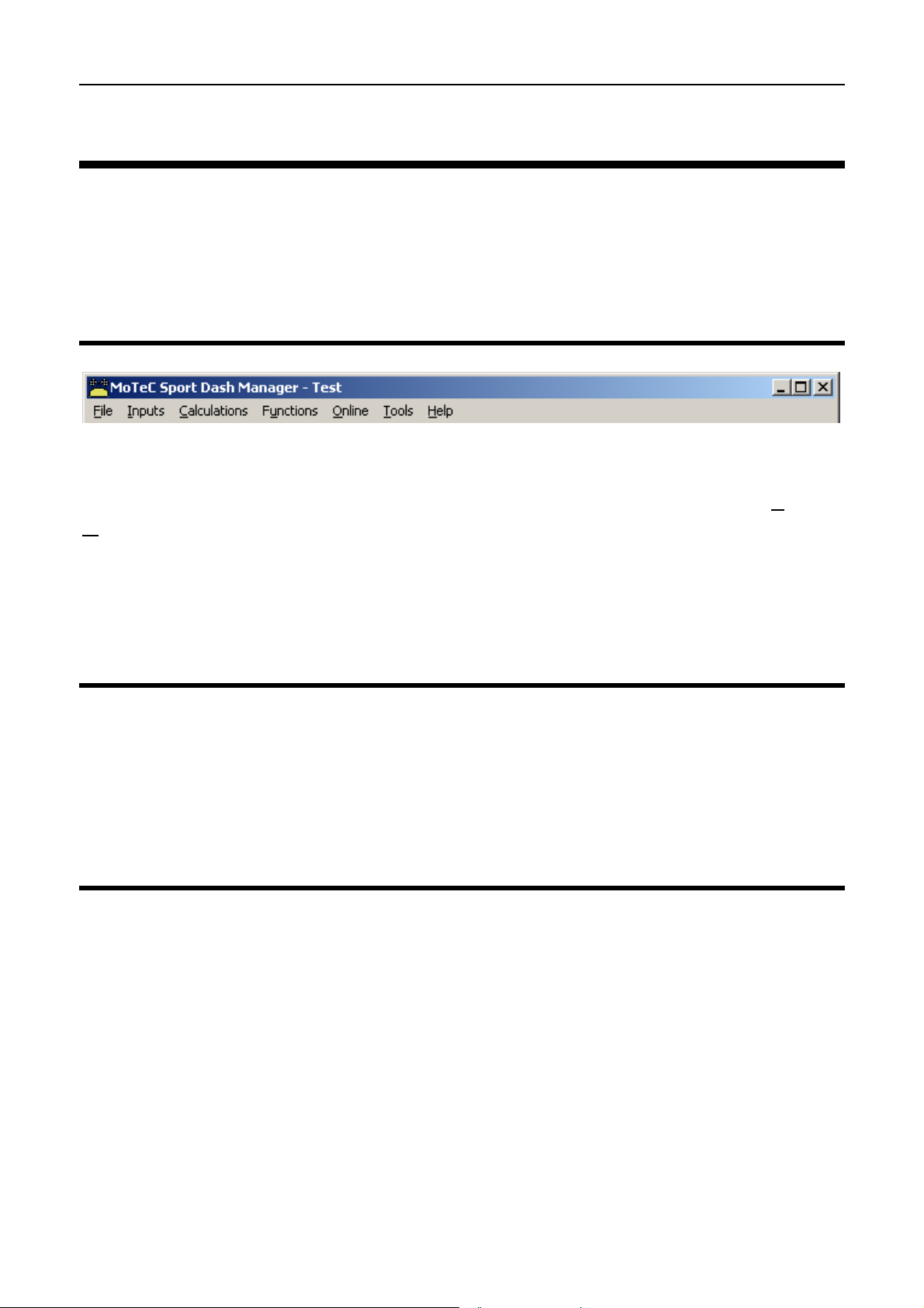
The main menu is used to access all of the features of the Sport Dash
Manager software. Click the mouse on one of the menu items or press the Alt
key together with the underlined letter, for example press Alt + F to select the
File menu.
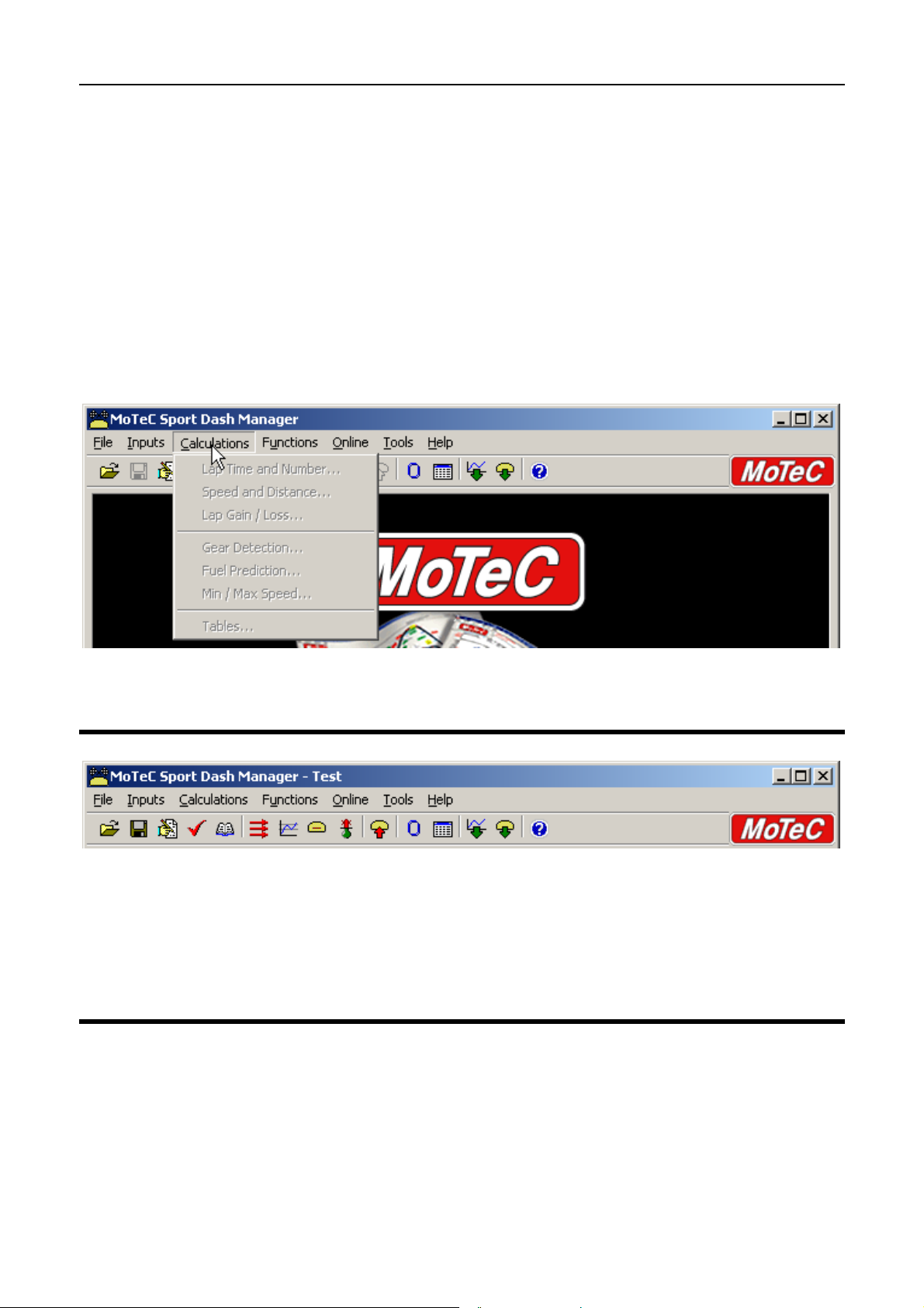
Unavailable Menu Items
When Sport Dash Manager is started the items related to changing the
configuration will be unavailable, this is because a configuration file has not
been selected.
Unavailable items appear grey as shown below.
Toolbar
The Tool Bar provides an alternative way of activating some of the commonly
used items on the main menu. To find out what each item does hold the
mouse pointer over the button of interest until a hint appears.
On line / Off line
All changes to the SDL configuration are performed ‘Off Line’, i.e. without the
PC communicating with the SDL. Once the configuration changes have been
made and saved to a file, they can be sent to the SDL which is an ‘On line’
process, i.e. the PC is communicating with the SDL.
Many other functions are also performed ‘On line’, for example, Get Logged
Data, Zero Sensors, Monitor Active channels etc.
Page 28

26 Sport Dash Manager Software
To consolidate the Online concept, all on line activities are placed in the
‘Online’ Menu item. All other menu items perform Off Line activit ies.
Configuration
The configuration of the SDL determines exactly how it operates.
The strength of the SDL lies in its flexibility of configuration. All aspects of the
SDL can be configured including, which sensor is connected to which input,
the calibration of each sensor, what to display and where to display it, what to
log and how fast to log it, tacho range, warning alarms, multi stage shift lights,
etc, etc.
Configuration Files
The SDL configurations are stored in files on the PC hard disk and can be
sent to the SDL at any time.
When changing the configuration, changes are only made to the file on the
PC. The file must be sent to the SDL before the changes take affect.
Creating a New Configuration File
A new configuration file can be created by selecting File | New from the main
menu, this will create a new configuration based on one of a number of
predefined templates.
After a new configuration has been defined, it should be saved with a
meaningful name by selecting File | Save from the main menu, the file may
then be sent to the SDL by selecting Online | Send Configuration from the
main menu.
Alternatively a new file can be created by loading an existing configuration file
and saving it to a new file by selecting File | Save As from the main menu.
Opening an Existing File
Before an existing configuration file can be modified or sent to the SDL it must
first be opened.
To open a configuration file select File | Open from the main menu and select
the desired file.
Page 29

MoTeC Sport Dash Manager Software 27
Note that the most recently used files appear at the bottom of the File menu,
which is often the easiest way to open a recently used file.
Sending the Configuration to the SDL
The currently open configuration file can be sent to the SDL by selecting
Online | Send Configuration from the main menu.
When a configuration file is sent to the SDL any changes are automatically
saved to the file.
Retrieving the Configuration from the SDL
The configuration can be retrieved from the SDL if ne cessary by selecting
Online | Get Configuration from the ‘Online’ menu. However this is not
normally necessary unless the original file is not available on the PC.
Backups
Whenever a file is saved, the previous contents of the file are saved in the
‘Save Backups’ directory. The total number of files is limited to 100.
When a file is sent to the SDL the existing SDL data is retrieved and stored in
the ‘From Dash Backups’ directory, this is in case the data in the SDL needs
to be restored. The total number of files is limited to 10.
File Management
The configuration files may be Renamed, Deleted, sent to a Memory stick etc,
by clicking the right mouse button on the desired file when the Open File
screen is displayed.
Changing the Configuration
Once an existing configuration file has been opened, or a new one created,
the various parts of the configuration may be modified by choosing the
appropriate items from the main menu. The configuration setup it ems are
accessed from the main menu items: Inputs, Calculations and Functions.
Configuration Sequence
The configuration is best setup in the following order:
1. Inputs (Input Pins & Communications)
Page 30

28 Sport Dash Manager Software
2. Calculations (Lap Time, Fuel Prediction etc)
3. Functions (Logging, Display, Alarms, Auxiliary Outputs etc)
This simplifies the setup procedure by ensuring that the required channels are
available for the functions that use them.
• Note that channels cannot be used until they have been generated by an
input, calculation or function.
Versions and Updating
Updating
The software inside the SDL can be updated by the user at any time to take
advantage of the latest features offered by MoTeC.
To update the SDL software version select Online | Upgrade Dash Version
from the Sport Dash Manager main menu.
Matching Versions
The version of software inside the SDL must match the version of Sport Dash
Manager software on the PC. If the versions do not match, Sport Dash
Manager will show a warning when it attempts to communicate with the SDL.
To check the version of Sport Dash Manager select Help | About MoTeC Sport
Dash Manager from the main menu.
To view the SDL firmware version, power up the SDL – the version is
displayed on the bottom line of the display for 2 seconds.
Configuration File Version
After the SDL version has been upgraded the configuration file in the SDL
must also be updated to match the new version. The display will show a
warning until a new configuration has been sent to the SDL.
Note that there is an option to automatically upgrade the configuration file in
the SDL when performing an upgrade. This eliminates the necessity to
manually upgrade the file and then sending it. (see Converting Older Version
Files)
Page 31

MoTeC Sport Dash Manager Software 29
r
A
A
Channels
Channels are used to convey information between the various systems of the
SDL. For example an input pin may feed a channel called ‘Engine
Temperature’, this channel may then be used by any other system, such as
the Display or Data Logging systems.
Channel Connection Example
Sensors
nalog
Inputs
Speed
Inputs
ECU
RS232
Comms
Data
Logging
System
Display
System
Alarm
System
Logging
Memory
LCD
Display
Gear
Detection
Auxiliary
Outputs
Fuel Pressure
Oil Pressure
Wheel Speed Front
Wheel Speed Rea
Engine RPM
Channels
Engine Temperature
larm Warning Light
Gear
Warning
Light
Page 32

30 Sport Dash Manager Software
Channel List
MoTeC has defined an extensive list of channels. All systems within the SDL
that generate values must choose to feed into one of these channels.
General Purpose Channels
Since the use of all channels can not be predetermined, a number of general
purpose channels have been included for o ccasions when a suitable
predefined channel is not available.
These channels may be required when measuring an uncommon value, or
when a general purpose function needs to generate a special output channel,
for example a 3D table may generate an output channel to control a valve of
some sort, in which case a general purpose channel may be used and
renamed appropriately.
Channel Usage
The SDL channel scheme allows complete flexibility in channel usage, as any
available channel can be used by any other function, i.e. any channel can be
logged, displayed, used in alarms, used as an input to the user definable
tables, etc.
Channel Properties
For each channel the following properties have been defined, some of which
may be modified by the user.
Note that it is only possible to modify channels that are already present in the
configuration.
Properties that may be modified by the user:
• Name
• Abbreviation
• Units (eg. Celsius, Fahrenheit etc)
Fixed Details
• Measurement Type (Temperature etc)
• Resolution (eg. 0.1 °C for Engine Temperature)
• Suitable Logging rates
Page 33

MoTeC Sport Dash Manager Software 31
• Suitable Display filtering
• Minimum and Max Range
Predefining these properties makes the channels easy to use throughout the
rest of the software, for example knowing the measurement type allows the
channels to be displayed in any units suitable for that type, with automatic
conversion between the units. For example all temperature channels can be
displayed in Celsius, Fahrenheit or Kelvin.
Channel Names & Abbreviations
The channels names may be changed if necessary. However name changes
should be limited to name preferences rather than redefining the purpose of
the channel, except for the general purpose channels which may be renamed
to suit the current use.
Channel Units
The units for a channel can be selected from a predefined list, for example the
Engine Temperature channel may have units of Celsius, Fahrenheit or Kelvin.
Conversion between units is automatically handled by the software.
Note that the units are used for display purposes only. This means t hat the
units can be changed at any time with out affecting the calibration of the
channel.
Channel Resolution
The resolution of all channels is fixed, for exam ple the resolution of the
Engine Temperature channel is fixed at 0.1 °C.
Fixed channel resolutions ensure that the unit conversion system works
properly and that channel comparisons can be performed correctly.
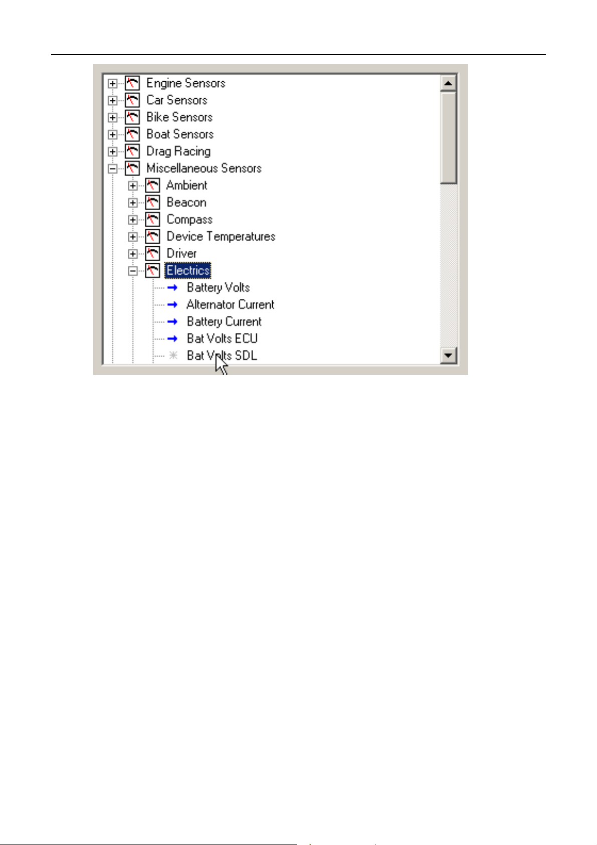
Selecting Channels
There are two methods of selecting channels, either the Category Method or
the Search Method.
Category Method
This method divides all the channels into categories and sub categories, so
that the list can be narrowed down to a small list of channels. For example,
the ‘Engine Sensors / Cooling’ category shows a list of channels associated
with the cooling system of the engine.
Page 34

32 Sport Dash Manager Software
When selecting a channel from the complete list of channels, it is usually
easiest to use the category selection method, for example when assigning a
channel to an input pin.
To expand a category click on the + sign next to the category name.
Page 35

MoTeC Sport Dash Manager Software 33
Search Method
This method lists all channels in alphabetical order and allows a channel to be
found either by typing the first few letters of any word in the channel name, or
by scrolling through the list.
Note that the words may be typed out of order so that ‘Engine Oil
Temperature’ could be found by typing "temp eng oil" or "oil t eng" or "e o t”
This method is most useful when selecting a channel from the available
channels. For example, if ‘Engine Temperature’ has been assigned to an
input pin, it can be easily located in the Search list, since this list normally only
contains 50 to 100 items.
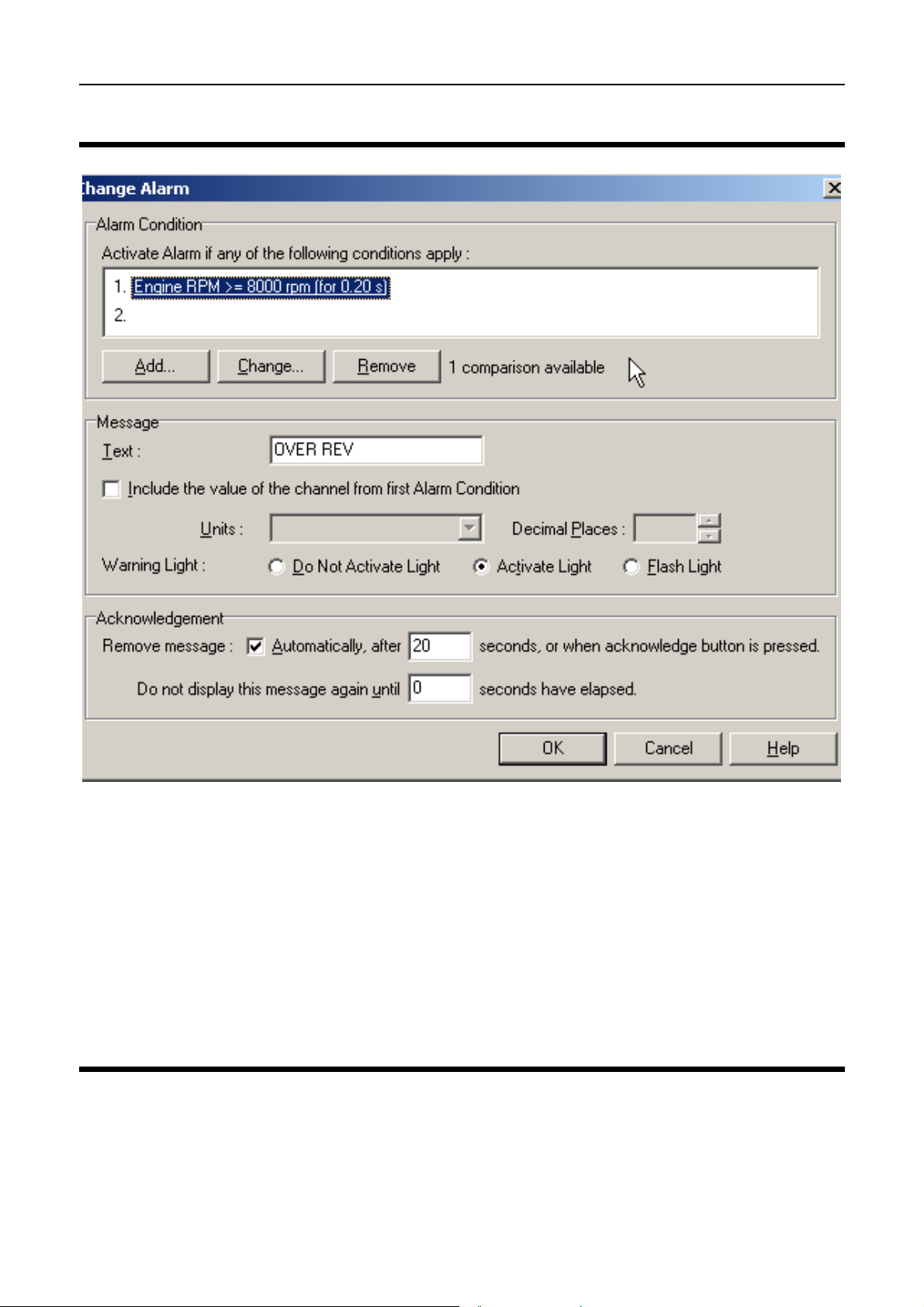
Conditions Overview
Conditions are used extensively throughout the software to define a true /
false condition based on comparing one or more channels to a value.
Conditions can be performed using 2 comparisons.
Conditions are used to define features such as when to start logging, or when
to activate an alarm.
For example an Engine Oil Pressure alarm may read as: Activate the alarm
when: Engine Oil Pressure < 200 kPa for 1 second AND Engine RPM > 1500
Page 36

34 Sport Dash Manager Software
RPM for 2 seconds. Note tha t a second alarm could be defined which would
cover the range from 500 to 1500 RPM, and which might read as: Engine Oil
Pressure < 50 kPa for 1 second AND Engine RPM > 500 RPM for 5 seconds.
The following shows an example of an Engine Oil Pressure alarm condition.
Checking Operation
Monitor Channels
The currently active channels can be monitored to allow checking of the
operation of all functions and measurements.
To monitor the active channels select Online | Monitor Channels from the
main menu.
Oscilloscope Screen
Any channel may also be shown on an oscilloscope sty le screen by pressing
the Utilities | Oscilloscope button on the Monitor Channels screen.
Tests
A number of tests are provided to check the operation of the SDL, such as the
Analogue Input and Auxiliary Output Tests. The Auxiliary Output test is very
useful for checking wiring and operation of shift lights for example. The
Analogue Input test is very useful when checking sensor wiring.
To run one of the tests select the appropriate test from the Online menu.
Page 37

MoTeC Sport Dash Manager Software 35
Sensor Zeroing
Some sensors require regular zeroing, for example Steering Angle,
Suspension Position, Ride Heights, G Force Sensors & Throttle Position.
Sport Dash Manager provides a screen to allow easy zeroing of all these
sensors.
To zero the sensors select Online | Zero Sensors from the main menu.
Details Editor
The Details Editor allows details about the Event, Venue, & Vehicle to be
entered.
This data is attached to the logged data file for later reference.
Some of this data is also attached to the configuration to determine the
operation of some functions, for example, the Fuel Tank Capacity is used to
determine Fuel Remaining, if used.
To change the details select File | Edit Details from the main menu.
Page 38

Page 39
MoTeC Windows Keyboard Use 37
Windows Keyboard Use
This section gives details on how to use the keyboard with Windows
applications.
Main Menu
The Main Menu can be acce ssed by holding down the Alt key then pressing
the key corresponding to the underlined letter in the menu name, followed by
the underlined letter of the item in the drop down menu. Eg Alt F, N for F
N
ew.
ile
Alternatively press and release the Alt key then select the desired menu item
using the arrow keys, then press enter to activate it.
Closing a Window
Enter = OK or Close (Only works when the OK or Cancel button has a bold
line around it)
Esc = Cancel or Close
Getting Help
To get help on the current screen or screen item press the F1 key, or press
Alt + H if the screen has a Help button.
To access the main help system select Help from the Main Menu.
Page 40
38 Windows Keyboard Use
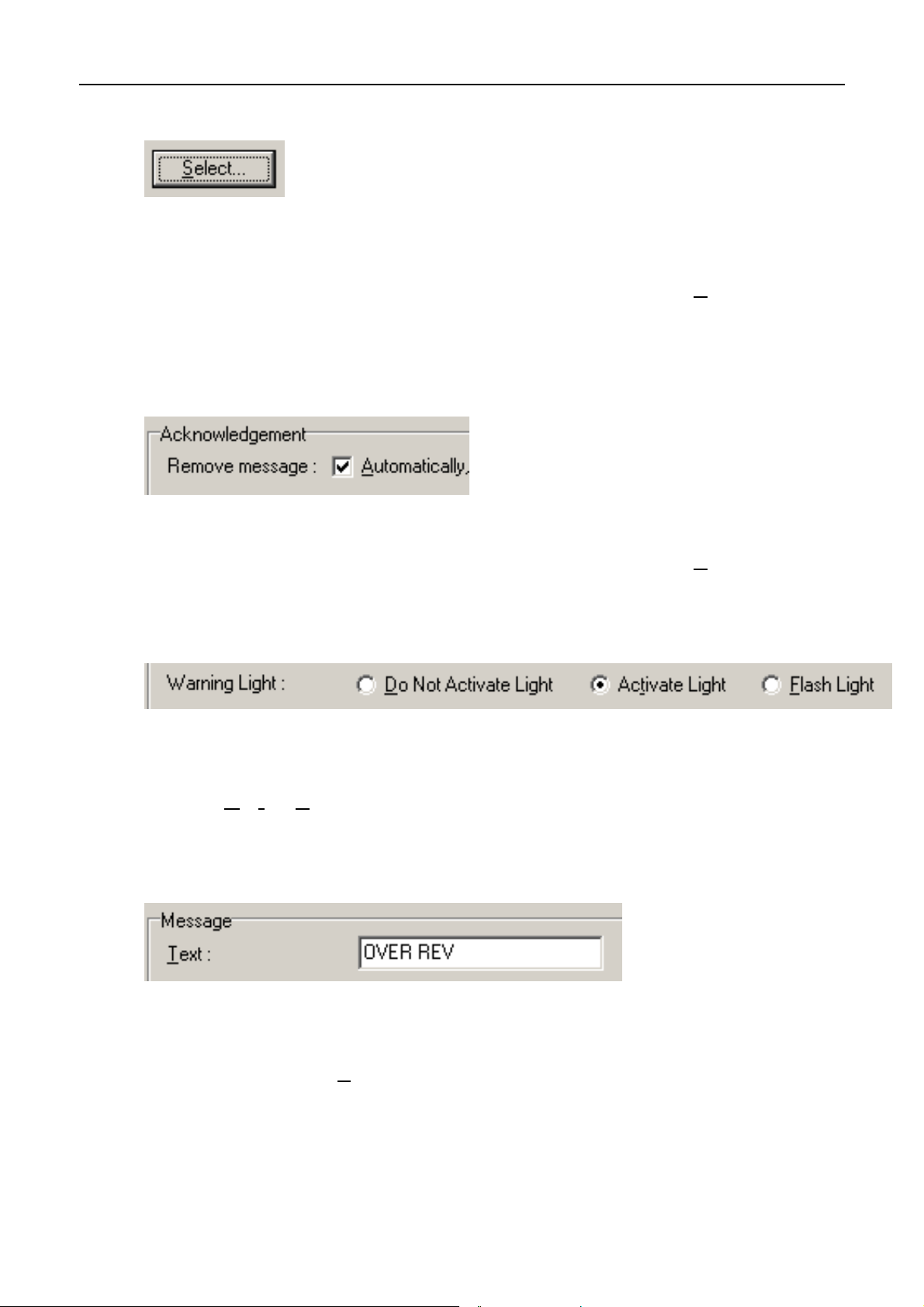
Selecting an Item in a Window
To access the various it ems in a window hold down the Alt key and press the
key corresponding to the underlined letter of the item of interest, for example
to select the ‘Flash Light’ item press Alt F
Alternatively the Tab key may be used to progress from one item to the next
(use Shift Tab to move backwards). The selected control is usually indicated
by a dotted line around it, or by highlighting the text or item selected within the
control.
Using the Selected Item
The method of using the selected item (or control) depends on what type of
control it is. The common controls are detailed below:
Page 41
MoTeC Windows Keyboard Use 39
Button
Buttons are generally used to show another screen or perform a
particular function.
Hold down the Alt key then press the underlined Letter ( S
navigate to the button using the Tab key then press the Enter key or
the Space Bar.
), or
Check Box
A check box is used to tick on or off a particular option.
Hold down the Alt key then press the underlined Letter ( A
navigate to the Check Box using the Tab key then press the Space Bar.
), or
Radio Buttons
Radio buttons are used to select an item from a group of options.
Hold down the Alt key then press the underlined Letter of the desired
option ( D
Tab key then use the arrow keys to select the desired item.
, t or F), or navigate to the Radio Buttons group using the
Edit
An edit control is used to enter a value or text.
Hold down the Alt key then press the underlined Letter of the text
above the edit box (T
type in the new value or text. Use the Backspace key or Del ete key to
remove unwanted characters
) or navigate to the button using the Tab key then
Page 42

40 Windows Keyboard Use
Drop down List
A drop down list is used to select from a number of items, but only t he
selected item is shown until a new item needs to be selected.
Hold down the Alt key then press the underlined Letter of the text
above the list ( L
select the desired item using the Arrow keys, Press the Enter key to
close the list.
) or navigate to the button using the Tab key then
Tabs
Tabs are used to select the different tab pages of a screen.
To select the next tab hold down the Ctrl key then press the Tab key.
To select the previous tab hold down the Ctrl key and Shift keys then
press the Tab key.
Tree View
A Tree View is used to select items from a hierarchical list
Up Arrow = Move the cursor up (selects the item above)
Down Arrow = Move the cursor down (selects the item below)
Right Arrow = Expand (Expandable branches indicated by a +)
Left Arrow = Collapse (Collapsible branches indicated by a -)
Page 43
MoTeC Windows Keyboard Use 41
Page 44

42 Appendices
Appendices
Appendix A: General Specifications
Physical
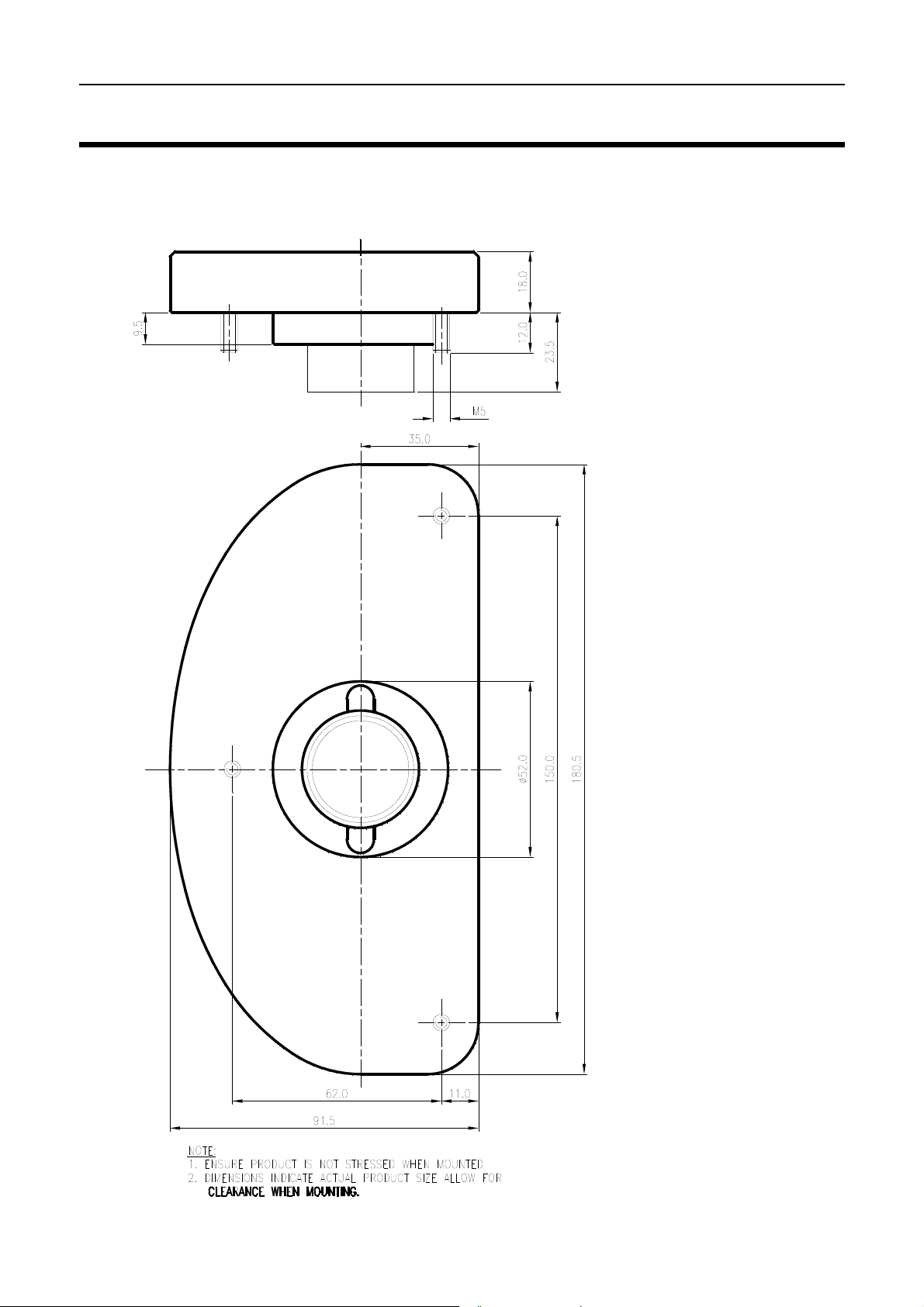
Case Size SDL: 180.5 x 91.5 x 18.0 mm (7.1 x 3.6 x 0.7 inches)
Weight 385 grams (0.85 lb)
Power Supply
Operating Voltage: 7 to 22 Volts DC
Operating Current: 0.15 Amps Typical (excluding sensor currents)
Reverse Battery Protection
Battery Transient Protection
Operating Temperature
Internal Temperature Range -10 to 80°C
Ambient Temperature Range -10 to 70°C typical
Sensor Supply Current
5V Sensor Supply : 0.2 Amps Max
8V Sensor Supply : 0.3 Amps Max
Internal Sensors
G Force Lateral
G Force Vertical
Battery Voltage
Dash Temperature
Page 45

MoTeC Appendices 43
Appendix B: Options Summary
The following options are available:
Pro Analysis Option
Advanced Analysis features in the Interpreter software, including:
• multiple graph overlays
• time variance between 2 laps
• statistical zoom on sections of data
• suspension analysis
• user math expressions
• track map section times
• track statistics
• lap maps
• XY graphs
Lambda Option
1 Wide Band Lambda (Air fuel ratio) measurement input.
Logging
Enables 8Mb of log memory
Page 46

44 Appendices
Appendix C: Sport Dash Manager Command
Line
Usage:
sportdash.exe -c[connection] -d -x -l -e -t -s [config file name]
[config file name]
(Optional)
Fully qualified path to the configuration file.
(eg "c:\motec\dash\config\SDL\bathurst.u11" )
Note: the path must included the file extension (eg .u11)
Options :
Each of the following options can be given as "/[character]" or "-[character]".
They are shown here as "-[character]".
-c[Connection Name]
(Optional)
Select a preconfigured connection by name as configured in the dash
connections dialog.
(eg -c"Primary CAN Connection").
Note: There must not be a space between the c and the connection name.
-d
(Optional)
Causes the debug console to be displayed.
Only available for debug builds.
-x
(Optional)
Causes the app to terminate when one the following tasks has been
performed.
Tasks :
One or more of the following may be specified.
-l
(Optional)
Page 47

MoTeC Appendices 45
Perform a “Get Logged Data” operation.
-e
(Optional)
Perform a “Get Engine Log” operation.
-t
(Optional)
Perform a “ Get Tell-tale Values” operation.
-p
(Optional)
Perform a “Print Summary” operation.
Note: The config file must be specified using a fully qualified path including
the file extension.
(eg -p "c:\motec\dash\config\SDL\bathurst.u11")
Note: There must be a space between -p and config name.
-s
(Optional)
Perform a “Send Configuration” operation.
Note: The config file must be specified using a fully qualified path including
the file extension.
(eg -s "c:\motec\dash\config\SDL\bathurst. u11" )
Note: There must be a space between -s and config name.
-u
(Optional)
Perform an “Upgrade Dash Version” operation.
Page 48

46 Appendices
Appendix D: Input Characteristics
Analog Voltage Inputs
Suitable for: Potentiometers, Voltage output sensors & Variable resistance
sensors with a pullup resistor
Measurement Voltage Range:
Inputs 1 to 4: 0 to 5.5 V
Inputs 5 to 8: 0 to 15.3 V
• Note that voltages outside this range may affect the readings on
other inputs.
Input Resistance: 100k ohms to 0V
Resolution:
Inputs 1 to 4: 1.35 mV
Inputs 5 to 8: 3.74 mV
Measurement Methods: Ratiometric, Absolute, Variable Resistance, Off/On
Update Rate (Inputs 1 to 4): 1000 times / second (for anti-aliasing)
Update Rate (Other inputs): 500 times / second (for anti-aliasing)
st
Filter: 150Hz 1
order
Calibration Accuracy
Gain (Ratiometric operation) 0.05% max
Gain (Absolute operation) 0.15% max
Offset ± 6 mV max
Linearity ± 6 mV max
Temperature Stability 60 ppm/°C max
Calibration Schedule 12 Months
Analog Temp Inputs
Suitable for: 2 wire variable resistance sensors and some voltage output
sensors.
Page 49

MoTeC Appendices 47
Measurement Voltage Range: 0 to 15 V
• Note that voltages outside this range may affect the readings on other
inputs.
Input Resistance: 1000 ohms pullup to 5V sensor supply + 100k to 0V
Resolution: 3.74 mV
Measurement Methods: Ratiometric, Absolute, Variable Resistance, Off/On
Update Rate: 500 times / second
st
Filter: 150Hz 1
order
Calibration Accuracy
Gain (Ratiometric operation) 0.05% max
Gain (Absolute operation) 0.15% max
Offset ± 6 mV max
Linearity ± 6 mV max
Temperature Stability 60 ppm/°C max
Calibration Schedule 12 Months
Lambda Input
Type: Wide Band MoTeC
Measurement Range: 0.75 to 1.50 Lambda (or 0 to 1V)
Accuracy: 1.5 % up to 1.20 Lambda
Update Rate: 100 times / second
Switch Inputs
Suitable for: Switch to 0V, or Off / On Voltage signal
Pullup Resistor: 4700 ohms to 5V
Voltage Range: 0 to 15V
Positive Trigger Threshold: 3.5 V max
Negative Threshold: 1.0 V min
Hysteresis: 0.5 V Min
Measurement Methods: Off/ On only
Page 50

48 Appendices
Filter Time Constant: 22usec
Digital Inputs
Suitable for: Switch to 0V, Logic signal & open collector device (eg Hall
Switch)
Pullup Resistor: 4700 ohms to 5V
Voltage Range: 0 to 15V
Positive Trigger Threshold: 3.5 V max
Negative Threshold: 1.0 V min
Hysteresis: 0.5 V Min
Update Rate: 100 times / second
Filter Time Constant: 22usec
Digital Input Measurement Methods
Frequency
Resolution 0.1 Hz
Maximum Frequency: 3200 Hz
Rising Edge Triggered
Period 1 usec
Measures period between rising edges
Resolution: 1 usec
Maximum: 32 msec
Period 100 usec
Measures period between rising edges
Resolution: 100 usec
Maximum: 3.2 sec
Pulse Width 1 usec
Measures pulse low time
Resolution: 1 usec
Page 51

MoTeC Appendices 49
Maximum: 32 msec
Pulse Width 100 usec
Measures pulse low time
Resolution: 100 usec
Maximum: 3.2 sec
Speed Inputs
Can be used in two modes: Hall or Magnetic.
In Hall mode a 4700 ohm pullup resistor is connected to 5V and the trigger
levels are fixed.
In Magnetic mode the pullup resistor is disengaged and the trigger levels can
be varied depending on the input frequency.
Update Rate: 100 times / second
Filter Time Constant: 25usec
Speed Input Measurement Methods
Frequency
Resolution 0.1 Hz
Maximum Frequency: 3200 Hz
Falling Edge Triggered
Period 1 usec
Measures period between falling edges
Resolution: 1 usec
Maximum: 32 msec
Period 100 usec
Measures period between falling edges
Resolution: 100 usec
Maximum: 3.2 sec
Page 52

50 Appendices
Pulse Width 1 usec
Measures pulse high time
Resolution: 1 usec
Maximum: 32 msec
Pulse Width 100 usec
Measures pulse high time
Resolution: 100 usec
Maximum: 3.2 sec
Speed Input Modes
HALL Mode
Suitable for switch to 0V, Logic signal or open collector device (eg Hall
Switch)
Pullup Resistor: 4700 ohms to 5V
Voltage Range: 0 to 15V
Positive Trigger Threshold: 3.0 V max
Negative Threshold: 2.8 V min
Hysteresis: 0.19 V Min
MAGNETIC Mode
Suitable for: Two wire magnetic sensor (Variable reluctance sensor)
Input Resistance: 100k ohms to ground (No Pullup)
Voltage Range: -100V to +100V
Programmable trigger levels
Analog Input Sampling
The following specifies the order in which the Analog input channels are
sampled and the time between samples.
Inter channel period is 14usec, except that for every 8 channels there is a
60usec gap.
Page 53

MoTeC Appendices 51
Sampling alternates between Group1 and Group2 and is scheduled every
1.000msec
Group1 Group2
AV1 AV1
AV2 AV2
AV3 AV3
AV4 AV4
AV5
AV6
AV7
AV8
Internal SDL Temp
Internal Battery Voltage
Internal Ref/2 AD2
Internal Ref/2 AD3
AT1 LA1
AV9 Internal 0V AD2
AT2
AV10 Internal 0V AD3
AT3 Internal Abs Ref 4V5
Internal Ref AD2
AT4 Internal Ref/2 AD1
Internal Ref AD3
Page 54

52 Appendices
Appendix E: Auxiliary Output Characteristics
Output Type: Open Collector (Drives to ground) with weak pullup (10k ohms)
to battery positive.
Control is by On/Off condition only, the Auxiliary outputs do not support
variable frequency or duty cycle control.
Current: 0.5 Amp max, current limited & thermal overload protected
Output Clamp: 50V Flyback Clamp (No Clamp Diode to supply).
Page 55

MoTeC Appendices 53
Appendix F: CAN Bus Specification
CAN Bus
Data Rate: 1Mbit/sec
Terminating impedance and data cable impedance: 100 ohms: dictated by the
PC communications cable (CAN cable)
Maximum length: 16 m (including the CAN Cable if present).
Page 56
54 Appendices
Appendix G: ECU to SDL Wiring (RS232)
The following details the methods for connecting the various MoTeC ECUs to
the SDL via RS232. In all cases this is done using the serial data stream
generated by the Telemetry function of each ECU.
In the case of the M800, M880 and M4e the SDL may be directly wired to the
ECU because these ECUs use RS232 interface levels. On the M48, M4 (pre
M4e) and the M8 a Computer Interface Module (CIM) or a PCI cable is
required to convert the signals to RS232.
M800 / M880
9 pin PC
Connector
(if used)
2
3
5
B17 / 40
B18 / 31
B14 / 13
34
M800 / M880
SDL
ECU
Note that the data to the SDL will be interrupted while a PC is connected
(DOS software only)
Note that the 9 pin connector is not used if using the Windows Calibration
software.
Note that data may be sent to the SDL via the CAN bus as an alternative to
the serial connection.
M4e
9 Pin PC
Connector
2
3
5
34
22
23
21
SDL
M4e ECU
Note that Older M4 ECUs require a different connection method
Note that the data to the SDL will be interrupted while a PC is connected.
Page 57

MoTeC Appendices 55
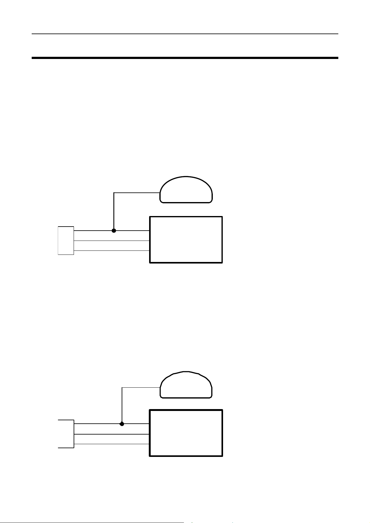
M48, M4 (pre M4e) a nd M8
The M48 & M8 and M4 (pre M4e) require the use of a CIM module or a PCI
Cable to convert the logic level signals used by these ECU’s into RS232
levels.
Using a CIM Module
34
12
CIM
PC Connector
Refer to the CIM module drawing for full wiring details.
Note that the data to the SDL will be interrupted while a PC is connected.
M4 / M48 / M8
SDL
ECU
Using a PCI Cable - Direct Connection
2
PCI Cable
(PC Interface Cable)
To connect a PC to the ECU disconnect the Computer Interface Cable from
the SDL and attach it to the PC.
34
SDL
M4 / M48 / M8
ECU
Page 58

56 Appendices
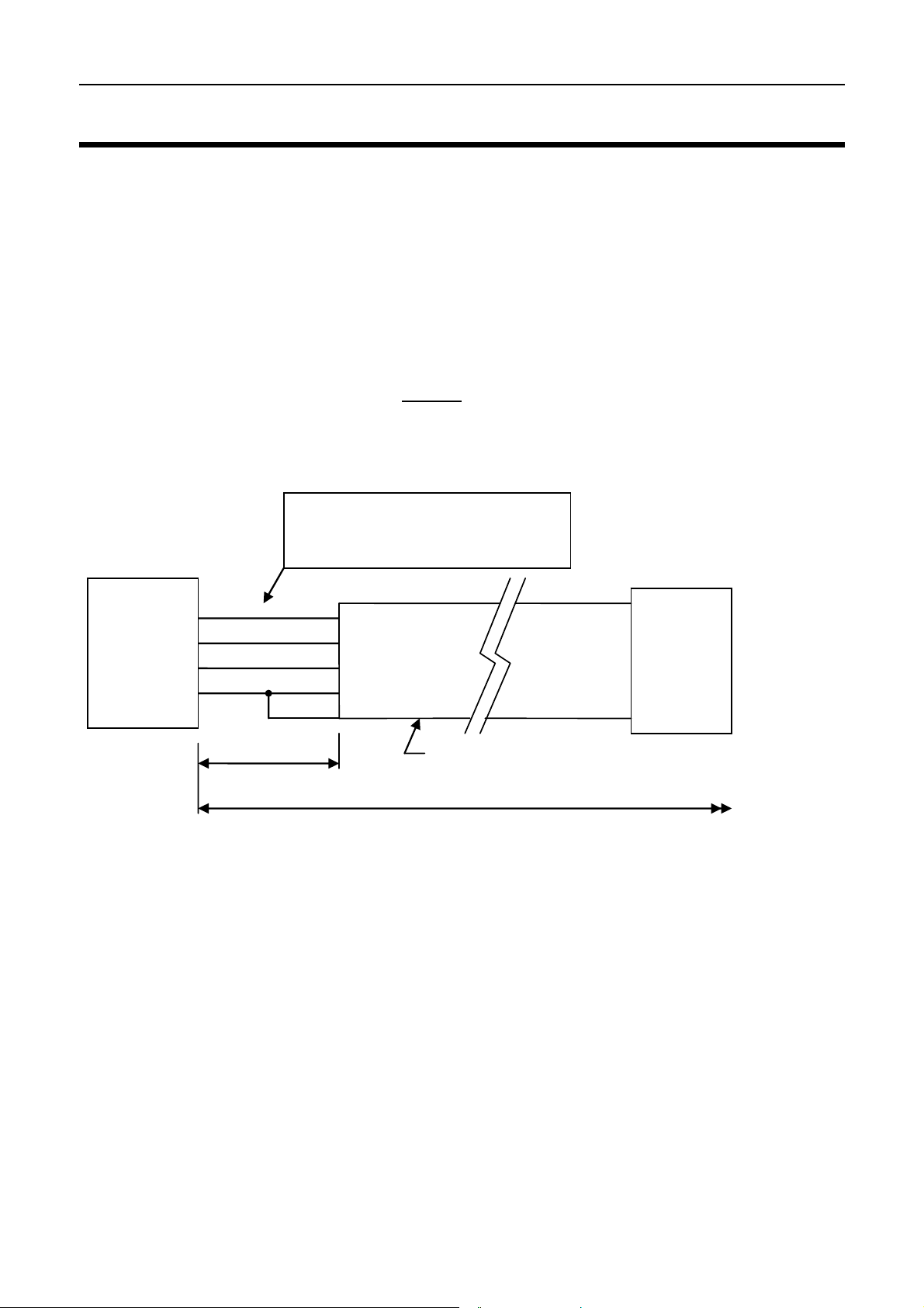
Appendix H: CAN Wiring
The CAN bus should consist of a twisted pair trunk with 100R (0.25Watt)
terminating resistors at each end of the trunk.
The preferred cable for the trunk is 100R Data Cable but twisted 22# Tefzel is
usually OK.
The maximum length of the bus is 16m (50ft)
CAN Devices (such as MoTeC SDL, BR2 etc) may be connected to the trunk
with up to 500mm (20in) of twisted wire.
Note that the “CAN Cable Connector” is not normally used since the SDL
uses USB for communications.
100R Terminating
Resi stors at each
end of the CAN Bus
CAN-HI
CAN-LO
100R
CAN-LO
CAN-HI
CAN Device
eg BR2
These wires must be Twisted
Minimum one twist per 50mm (2in)
500mm
<< CAN Bus >>
500mm
Max
CAN-LO
CAN-HI
CAN Device
eg M800
CAN-HI
CAN Device
eg SDL
CAN-LO
Max
CAN Cable
Connector
5
4
3
1
CAN-LO
CAN-HI
500mm Max
0V
8V
100R
Page 59
MoTeC Appendices 57
Appendix J: USB Wiring
The USB connection should be made by wiring a USB cable to the SDL main
connector as shown below:
The USB cable should have a type B socket so that a standard USB A to B
cable can be used to connect between it and the PC. MoTeC can provide a
suitable cable (these are not commonly available).
Note that the maximum length from ADL to the PC is 5m (16ft) when using a
normal USB cable. This can be extended in steps of 5m (16ft) up to a
maximum of 25m (80ft) by using Active
Wiring Details:
It is recommended that the USB
wires are reterminated to 22#
Tefzel to avoid wire breakage
SDL
USB extender cables or hubs.
USB B Type
Socket
USB-VCC
USB-DM
USB-DP
USB-GND
10
24
25
9
50mm (2in) Max
Maximum length 5m (16ft) including the cable to the PC
Red
White
Green
Black
Shield
Must be USB certified cable
Note: When inserting the pins into the Autosport connector check that all the
pins are latched correctly by pulling on each wire – it is very easy for a pin not
to latch correctly which will give an intermittent connection.
Page 60

58 Appendices
Appendix K: Typical Wiring (with BR2)
The wiring below shows typical wiring for BR2 on CAN plus USB for PC
connection.
For more detail on the CAN Bus wiring refer to Appendix H: CAN Wiring.
For more details on USB wiring refer to Appendix J: USB Wiring.
USB B
BR2
Ground
SwOut
Power
CAN-LO CAN-LO
CAN-HI CAN-HI
1
2
3
4
5
37
13
35
36
0V
8V
SDL
USB-VCC
USB-GND
USB-DM
USB-DP
10
24
25
9
Red
White
Green
Black
Shield
Type
Socket
CAN-HI
CAN-LO
100R
See the CAN Bus
Wiring Specification
for more detail
CAN Device
eg M800
ECU
Any Other
CAN Device
100R
See the USB
Wiring
Specification
for more detail
Page 61

MoTeC Appendices 59
Appendix L: Pin List by Function
Pin Name Function
Battery Power
4 BAT- Battery Negative
3 BAT+ Battery Positive
Analog Volt Inputs
15 AV1 Analog Voltage Input 1
16 AV2 Analog Voltage Input 2
17 AV3 Analog Voltage Input 3
18 AV4 Analog Voltage Input 4
1 AV5 Analog Voltage Input 5
2 AV6 Analog Voltage Input 6
19 AV7 Analog Voltage Input 7
20 AV8 Analog Voltage Input 8
Analog Temp Inputs
21 AT1 Analog Temp Input 1
22 AT2 Analog Temp Input 2
31 AT3 Analog Temp Input 3
32 AT4 Analog Temp Input 4
Lambda Input
29 LA- Lambda Input Negative
30 LA+ Lambda Input Positive
Switch Inputs
11 SW1 Switch Input 1
12 SW2 Switch Input 2
Digital Inputs
27 DIG1 Digital Input 1
28 DIG2 Digital Input 2
Speed Inputs
23 SPD1 Speed Input 1
26 SPD2 Speed Input 2
Page 62

60 Appendices
Auxiliary Outputs
5 AUX1 Auxiliary Output 1
6 AUX2 Auxiliary Output 2
7 AUX3 Auxiliary Output 3
8 AUX4 Auxiliary Output
8V Sensor
13 8V Sensor 8V
5V Analog Sensor
14 5V Sensor 5V Analog Volt & Analog Temp
0V Analog Sensor
37 0V Sensor 0V Analog Volt & Analog Temp
CAN Interface
35 CAN-LO CAN-LO
36 CAN-HI CAN-HI
USB
9 USB-GND USB Ground (Black + Shield)
10 USB-VCC USB Power (Red)
24 USB-DM USB Data Minus (White)
25 USB-DP USB Data Plus (Green)
RS232
33 TX RS232 Output
34 RX RS232 Input
Page 63

MoTeC Appendices 61
Appendix M: Pin List by Pin Number
Pin Name Function
1 AV5 Analog Voltage Input 5
2 AV6 Analog Voltage Input 6
3 BAT+ Battery Positive
4 BAT- Battery Negative
5 AUX1 Auxiliary Output 1
6 AUX2 Auxiliary Output 2
7 AUX3 Auxiliary Output 3
8 AUX4 Auxiliary Output 4
9 USB-GND USB Ground (Black + Shield)
10 USB-VCC USB Power (Red)
11 SW1 Switch Input 1
12 SW2 Switch Input 2
13 8V Sensor 8V
14 5V Sensor 5V
15 AV1 Analog Voltage Input 1
16 AV2 Analog Voltage Input 2
17 AV3 Analog Voltage Input 3
18 AV4 Analog Voltage Input 4
19 AV7 Analog Voltage Input 7
20 AV8 Analog Voltage Input 8
21 AT1 Analog Temp Input 1
22 AT2 Analog Temp Input 2
23 SPD1 Speed Input 1
24 USB-DM USB Data Minus (White)
25 USB-DP USB Data Plus (Green)
26 SPD2 Speed Input 2
27 DIG1 Digital Input 1
28 DIG2 Digital Input 2
29 LA1- Lambda Input Negative
30 LA1+ Lambda Input Positive
31 AT3 Analog Temp Input 3
32 AT4 Analog Temp Input 4
33 TX RS232 Output
34 RX RS232 Input
35 CAN-LO CAN Lo
36 CAN-HI CAN Hi
37 0V Sensor
Page 64

62 Appendices
Appendix N: Connector
SDL Mating Connector
37 way Deutsch: AS6-14-35SN
Wire
Wire to suit connector: 22# Tefzel, Mil Spec : M22759/16-22
Crimp Tool
Crimp Tool : M22520/2-01
Positioner for Crimp Tool : M22520/2-07
• Note that the Crimp Contacts are type 22D (needed to set the crimp tool
correctly)
Wire Stripping Tool
The following tool is recommended
Ideal Industries 45-2133 stripping tool with LB1195 wire stop.
Heatshrink Boots
Straight: Raychem 202K142, Hellerman 155-42-G
Right Angle: Raychem 222K142, Hellerman : 1155-4-G
Page 65

MoTeC Appendices 63
Appendix P: Wire Specifications
M22759/16 Wire Ratings (For Various Wire Gauges)
Insulation Material : Tefzel
Conductor : Tin Plated Copper
Voltage Rating : 600 V
Maximum Temperature : 150 °C
Wire
Gauge
(AWG)
22 0.38 5 0.045 14
20 0.61 6 0.028 8.5
18 0.96 9 0.018 5.5
16 1.2 12 0.014 4.3
14 1.9 18 0.009 2.7
12 3.0 24 0.006 1.8
Cross
Sectional
Area (mm
2
)
Max Current
at 100 °C
Ambient
(Amps)
Resistance
( ohm / m )
Resistance
( ohm / 1000 ft )
Wire Stripping Tool
The following tool is recommended
Ideal Industries 45-2133 stripping tool with LB1195 wire stop.
Page 66
64 Appendices
Appendix Q: Case Dimensions
SDL
Page 67

MoTeC Notes 65
Page 68

66 Notes
Page 69

MoTeC Notes 67
Page 70

68 Notes
 Loading...