

Page 1
PWC Plug-In ECU Kit
•Yamaha FX-SHO, FZS/FZR
•Kawasaki Ultra 250X,260X
•Sea-Doo RXP/RXPX/RXT
•Hydrospace S4
INSTALLATION MANUA L
Page 2

MoTeC PWC Plug-In ECU Manual
Copyright 2010 – MoTeC Pty Ltd
The information in this document is subject to change without notice.
While every effort is taken to ensure correctness, no responsibility will be taken for the
consequences of any inaccuracies or omissions in this manual.
PN 63036 V 4.1, November 2010
Page 3

ii PWC Plug-In ECU Manual
Contents
Quick Start Guide .................................................................... v
Installation ............................................................................................. v
Data Logging ........................................................................................ v
Expanding the System ..........................................................................vi
More Information...................................................................................vi
Introduction .............................................................................. 1
Features ................................................................................................ 1
System Overview .................................................................................. 2
Yamaha Installation ................................................................. 3
System .................................................................................................. 3
Installation ............................................................................................. 4
Optional Installation - Cooling Kit ............................................... 4
PWC Operational Differences .............................................................. 5
ECU Operation ........................................................................... 5
Drive by Wire Throttle ................................................................. 5
Instrument Cluster Operation ..................................................... 5
Cooling ....................................................................................... 6
Power Control Strategy .............................................................. 6
Security ....................................................................................... 7
Kawasaki Installation .............................................................. 8
System .................................................................................................. 8
Installation ............................................................................................. 8
PWC Operational Differences ............................................................ 11
ECU Operation ......................................................................... 11
Instrument Cluster Operation ................................................... 11
Cooling ..................................................................................... 11
Power Control Strategy ............................................................ 12
Security ..................................................................................... 12
Idle Stepper Motor Setting (V3.52P or later) ............................ 12
Sea-Doo 2004-2009 Installation ............................................ 14
System ................................................................................................ 14
Page 4

MoTeC PWC Plug-In ECU Manual iii
Installation ........................................................................................... 15
Configuration File ..................................................................... 16
PWC Operational Differences ............................................................ 17
ECU Operation ......................................................................... 17
Instrument Cluster Operation ................................................... 17
Power Control Strategy ............................................................ 18
Security ..................................................................................... 18
Idle Stepper Motor Setting (V3.52P or later) ............................ 18
Fuel Pump current .................................................................... 19
Sea-Doo 2010 Installation ..................................................... 20
System ................................................................................................ 20
Installation ........................................................................................... 21
Configuration File ..................................................................... 23
PWC Operational Differences ............................................................ 24
ECU Operation ......................................................................... 24
STC-SX Device ........................................................................ 24
iBR Brake System Operation ................................................... 24
Instrument Cluster Operation ................................................... 24
Power Control and Engine Start Strategy ................................ 25
Connecting to a PC with MoTeC UTC cable ............................ 25
Hydrospace S4 Installation ................................................... 26
System ................................................................................................ 26
Installation ........................................................................................... 27
Configuration File ..................................................................... 28
PWC Operational Differences ............................................................ 28
Instrument Cluster Operation ................................................... 28
Power Control Strategy ............................................................ 28
Launch Mode Button ................................................................ 29
Software Installation .............................................................. 30
ECU Manager Software (V3.52P or later) .......................................... 30
Connecting the ECU to a PC.................................................... 31
i2 Data Analysis Software ................................................................... 31
Data Logging .......................................................................... 32
Change the Logging Settings ............................................................. 33
Page 5

iv PWC Plug-In ECU Manual
Options to Expand the System ............................................. 35
GPS .................................................................................................... 35
Upgrades ............................................................................................ 35
Appendices ............................................................................ 37
Specifications ...................................................................................... 37
Yamaha .............................................................................................. 38
Connectors ............................................................................... 38
Pin List by Function .................................................................. 39
Calibration and Wiring Notes.................................................... 43
Kawasaki ............................................................................................ 46
Connectors ............................................................................... 46
Pin List by Function .................................................................. 47
Calibration and Wiring Notes.................................................... 50
Output Test Function ................................................................ 52
Sea-Doo 2004-2009 ........................................................................... 53
Connectors ............................................................................... 53
Pin List by Function .................................................................. 54
Calibration and Wiring Notes.................................................... 58
Sea-Doo 2010 ..................................................................................... 61
Connectors ............................................................................... 61
Pin List by Function .................................................................. 62
Calibration and Wiring Notes.................................................... 66
Hydrospace S4 ................................................................................... 68
Connectors ............................................................................... 68
Pin List by Function .................................................................. 69
Calibration and Wiring Notes.................................................... 72
Lambda Sensor Installation ................................................................ 74
Base Maps .......................................................................................... 77
Glossary .............................................................................................. 78
How to Get More Information ............................................................. 80
Page 6

MoTeC Quick Start Guide
icons to indicate information
as a complete replacement kit including
direct power gain.
ensure that your M400 Marine ECU has the
) and that a
you fit the
may not power up,
may not start, or may permanently damage the ignition coils.
Detailed installation instructions can be found in the section relevant for your
................................
................................
..............................
................................
................................
To take full advantage of the possibilities of the system, data logging can
valuable knowledge about the performance and reliability of
for a free
Quick Start Guide
v
Throughout this manual we use the following
valid for a particular PWC:
Yamaha
Kawasaki
Sea-Doo
Hydrospace S4
Installation
The PWC Plug-In ECUs are supplied
a Base Map to provide a tune for the craft that will result in
Warning:
Your dealer must
correct firmware loaded (currently V3.52P or later
suitable configuration file (Base Map) is loaded, before
kit to your PWC.
Failure to do this may result in a PWC which
PWC.
You should read:
• Yamaha Installation ................................
• Kawasaki Installation ................................
• Sea-Doo 2004-2009 Installation ................................
• Sea-Doo 2010 Installation ................................
• Hydrospace S4 Installation ................................
only
................... 3
................. 8
14
....... 20
...... 26
Data Logging
provide you with
the engine and craft.
Note: The PWC Plug-In ECU systems provide data logging
Page 7

vi Quick Start Guide
evaluation period of the first 8 hours engine running time. After this evaluation
period data logging is available as an Upgrade.
This manual will explain how to obtain the logged data from your PWC.
You should read:
• Software Installation ................................................................................ 30
• Data Logging ........................................................................................... 32
Expanding the System
To get even more out of your PWC, you will find information in this manual on
how you can expand your system.
You should read:
• Options to Expand the System ................................................................ 35
• Appendices .............................................................................................. 37
More Information
If you would like to explore more in depth information for your installation, you
will find tips and links for further reading in the last appendix.
You should read:
• How to Get More Information .................................................................. 80
Page 8

MoTeC Introduction 1
Introduction
The PWC Plug-In ECUs are direct replacements for factory ECUs on a select
number of popular PWC models. They are based around the M400 Marine
ECU.
Note: ECUs (Engine Control Units) are often referred to as Ignition Systems.
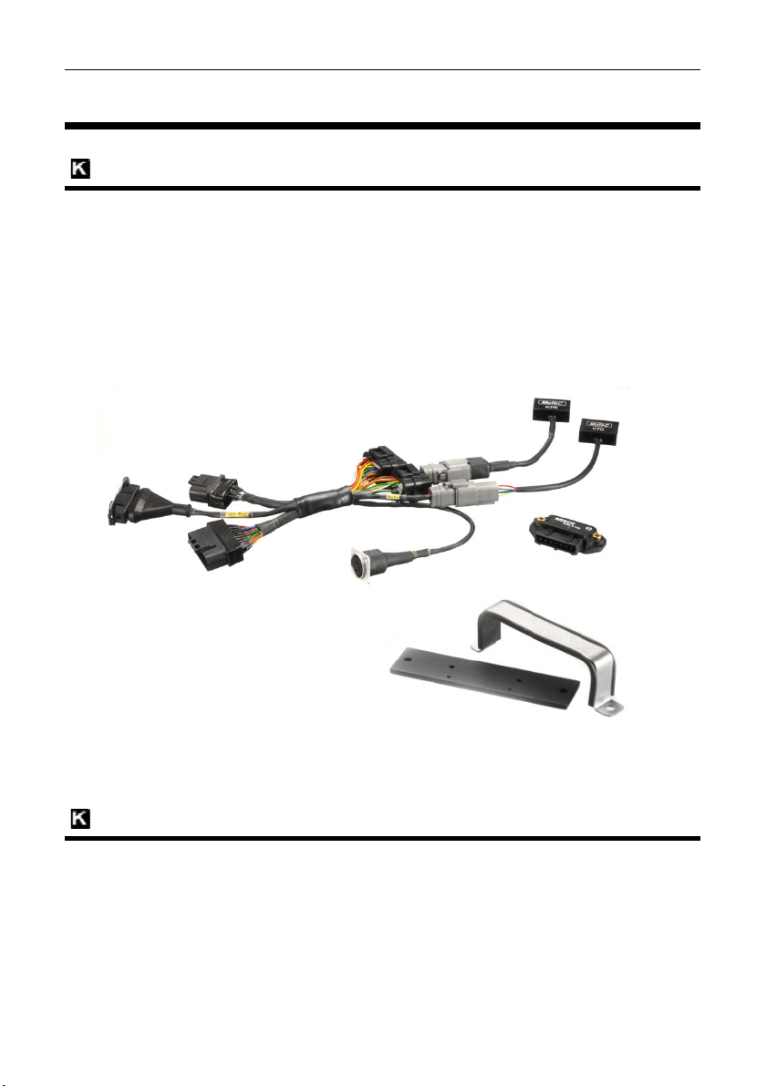
Complete with a wiring loom and mounting brackets, PWC Plug-Ins are
convenient and cost effective to install because they eliminate the need to
rewire the PWC. They simply plug into the factory wiring harness using the
original sensors, fuel system and factory dash.
Features
The M400 Marine ECU comes with a range of features as standard and
several options available as upgrades to customise and grow your system.
These additional features are activated through a simple password acquired
from MoTeC, at any time when you need it. See Upgrades.
Engine Tuning Features
• Windows based ECU Manager tuning software with user definable screen
layouts.
• Individual cylinder tuning of both fuel delivery and ignition timing.
• Selectable channels for table axes.
• Fully configurable axis points on all tables.
• Free access to wideband Lambda and data logging for initial tuning.
Available for the first 8 hours engine running time.
• Possibility to communicate directly with OEM dash.
• Suitable for engines requiring the latest complex control functions, such
as drive by wire throttle control.
• Capable of all other modern control functions, such as:
o Launch control
o Overrun boost enhancement (anti-lag)
o Boost control
o Nitrous injection
• Fully configurable sensor inputs including custom calibrations.
• Configurable receiving and transmitting data via the CAN bus.
• Capable of receiving data from multiple Lambda measurement devices
via CAN.
Page 9

2 Introduction
crank trigger
in digital oscilloscope
Internal data logging (500 kB) with fast download via CAN
data analysis software
loom and required devices.
, including all brackets and fasteners to install the ECU
• Integrated advanced diagnostics, including injector and
diagnostics.
• Switchable between multiple configurations.
• Ref/Sync capture displayed on the built-
Data Acquisition
•
• Three engine histogram logs including a tell-tale log.
• State of the art i2 Standard or i2 Pro
Compatibility
Yamaha WaveRunner FX SHO, FZR and FZS.
Kawasaki Ultra 250X and 260X Jet Ski.
Sea-Doo RXP, RXP-X, RXT, and RXT-X
Hydrospace S4
Required Accessories
UTC (only required to connect the ECU to a laptop).
System Overview
MoTeC
.
.
.
Each system is tailored to the specific PWC and consists of
• M400 Marine ECU.
• Installation Set, including adaptor
• Mounting Set
and peripheral devices.
Page 10
MoTeC Yamaha Installation
In ECU is available with the M800
Yamaha Installation
System
ECU
• M400 Marine ECU
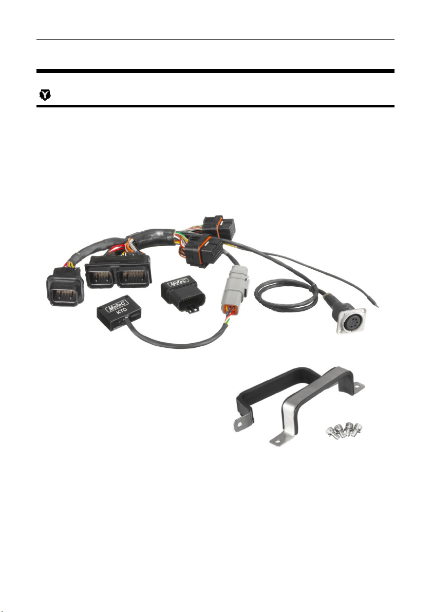
Installation Set
• 1 x Adaptor Loom
• 1 x KTC (K-Line to CAN module)
• 1 x Immobiliser Bypass
3
Mounting Set
• 2 x ECU mounting brackets
• 4 x mounting bolts
• 1 x rubber backing pad
On request the Yamaha PWC PlugECU.
Marine
Page 11
4 Yamaha Installation
lectrical
rubber insert under the M400 and
with the existing bolt holes in the plastic
tied to a suitable anchoring position.
Immobiliser Bypass which replaces
ders the PWC permanently unlocked.
, simply unplug the Yamaha Immobiliser and
mmobiliser
e right front si
engine power
the cooling
can be run f
nit to the engine. Cooling kits can be purchased from PWC parts suppliers
R&D Cooling Kit
performance.com/newProducts/yamaha/fzr.asp
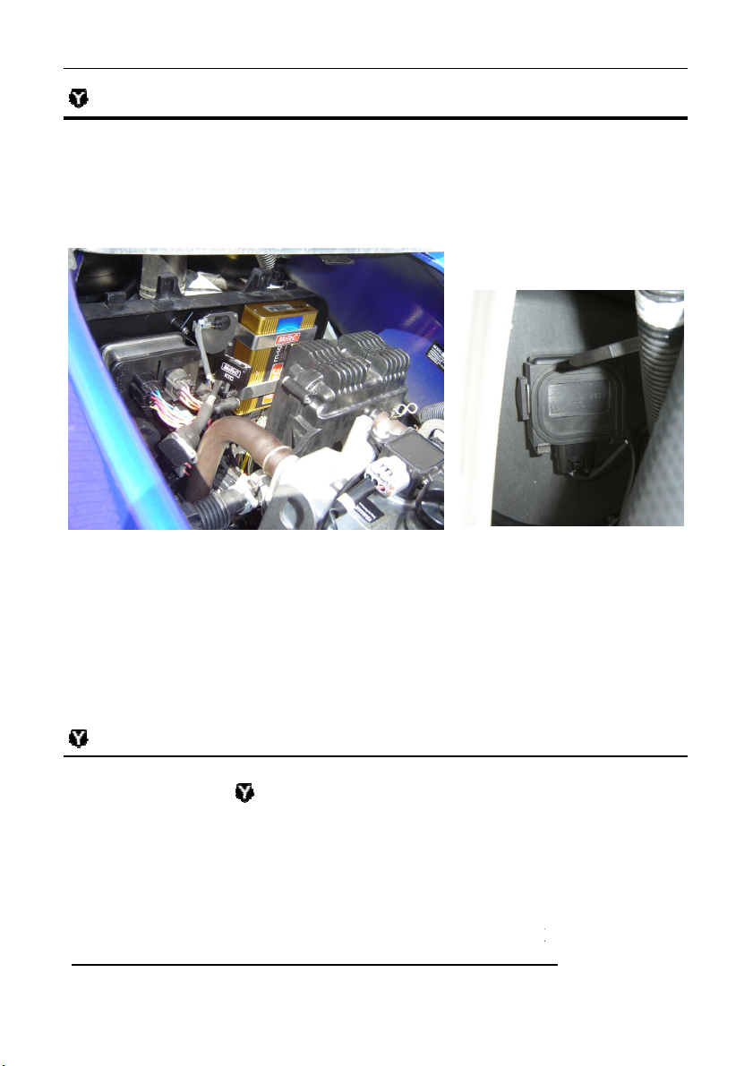
Installation
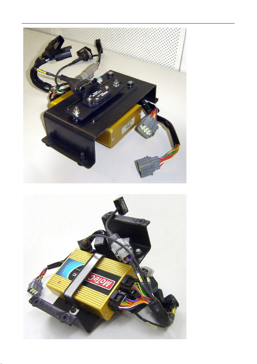
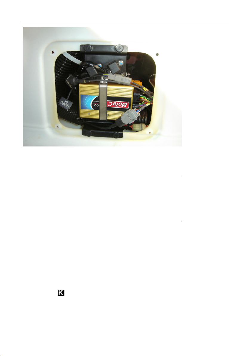
ECU and KTC
The M400 Marine ECU replaces the factory ECU in the e
located behind the engine. Place a
the ECU mounting brackets
bulkhead. The KTC device can be zip-
Immobiliser Bypass
The Yamaha Installation Set includes the
the original Yamaha Immobiliser and ren
To install the Immobiliser Bypass
plug the MoTeC Immobiliser Bypass into the loom. The I
behind the front storage compartment bulkhead, on th
hull.
MoTeC
box which is
allign
is located
de of the
Optional Installation - Cooling Kit
When a MoTeC Plug-In ECU is fitted, the increased
in over-heating (See Cooling).
Removing the standard engine thermostat will improve
The thermostat is located at the rear of the cylinder head.
To further assist engine cooling, extra cooling lines
u
such as R&D and Riva.
Acceptable results have been reported using
(http://www.rd-
rom the jet
# 660-18001.
)
could result
slightly.
Page 12
MoTeC Yamaha Installation
the standard OEM operation.
some operational differences
ECU engine control functionality is the same as the
are possible, with the
All Yamaha WaveRunner models are fitted with a Drive by Wire
is a safety related device. If it is not functioning
onic Throttle settings in the ECU. Incorrect
can potentially be dangerous and result in serious injury.
instrument cluster
Line to CAN) data
, and then transmits K
custom data set are
dash alarms and rev limits
Dash alarm
These alarms and rev limits are similar to the factory settings.
PWC Operational Differences
5
The PWC Plug-In ECU closely mimics
MoTeC would like to draw your attention to
when a PWC Plug-In ECU is installed.
ECU Operation
The M400 Marine
standard factory ECU; all normal operations of the PWC
exception of No Wake Mode and Cruise Control.
Drive by Wire Throttle
(Electronic Throttle). This
correctly contact your MoTeC dealer for further advice.
Warning:
Never alter any of the Electr
operation
Instrument Cluster Operation
The M400 Marine ECU will control the Yamaha
the original factory dash operation.
The ECU controls the dash via the KTC (KKTC receives CAN messages from the ECU
messages to the instrument cluster.
The fixed CAN address and the CAN messages
in the Base Map and should not be changed.
To prevent engine damage the following
provided:
Sensor Value
Engine Temperature
approx. 88 °C (190 F)
yes
However,
throttle
s and mimic
adaptor; the
-Line
provided
are
Rev Limit
3300 rpm
Muffler Temperature
Oil Pressure None yes
Note:
96 °C (205 F)
yes
None
4500 rpm
Page 13

6 Yamaha Installation
In ECU is fitted the engine power is increased. T
n its supply of
It is important to check if the cooling system is working adequately. The
If your engine overheats the dash alarm will come on and the revs will be
emperature monitors on the Yamaha.
front right side of the
is used to control the dashboard alerts and RPM limiter
the rear right side of
engine temperature
. When the engine
uses full throttle for extended periods, the engine tuner can adjust two
compensation tables to reduce engine temperature. The fuel mixture can be
can be retarded
The logged data will be useful to check the engine temperature. See
l installation of a cooling kit will help with engine cooling.
Yamaha WaveRunner uses an Immobiliser and Start Button to
. If the Immobiliser is unlocked, pressing the Start Button on
In ECU bypasses the Immobiliser
follows the same strateg
longer than 30
seconds, the M400 Marine ECU turns off its own power. Power is not re
utton is pressed again for an engine start.
ustments to the M400 Marine ECU
Manager software, an ECU reset may be required. In this case, power is
removed from the ECU and the CAN connection to the PC software is
utton for a short time until the
ne has cranked, or for a longer time if you want the engine running.
Cooling
MoTeC
When a PWC Plugstandard Yamaha cooling system might not be sufficient i
to the engine and over-heating can occur.
maximum engine temperature should be 88 °C (190 F).
limited to 3300 rpm.
Note: There are three separate engine t
The engine temperature switch, mounted on the
block,
temperature of this switch is 88 °C and is not adjustable.
The engine temperature sensor, mounted on
will reduce the drive-by-wire throttle when
105 °C.
A further precaution is controlled by the Full Throttle Timer
enriched using Fuel Comp 1 table and the ignition timing
using Ignition Comp 2 table.
Tip:
Data Logging on how to access the logged data.
The optiona
Power Control Strategy
he
water
engine
. The alarm
the block,
exceeds
The standard
power up the craft
the left handlebar will start and run the engine.
The installation of the PWC Plugthe PWC permanently unlocked. Otherwise it
some provisions:
• If the engine is not started or is stopped for a period
applied until the Start b
• When making tuning adj
halted. To re-connect, press the Start B
engi
using ECU
rendering
y with
-
Page 14

MoTeC Yamaha Installation
establish and you may continue with
If the ECU needs to be powered for longer than 30 seconds without the
logging
he ECU power should be controlled externally.
Adaptor
power relay.
round wires from the M400 pins B14, B15 or B16 for this
(see Appendices for
When finished, this wire should be lifted from ground to return to normal
power control operation, so the ECU has control of the power relay. Failure to
The standard Yamaha Immobiliser system uses a Key Fob transmitter to
Lock/Unlock the PWC. If the immobiliser is locked, the Start button will not
ser Bypass device
, for example by
power relay.
The CAN connection should retuning adjustments.
Power-up Adaptor Wire
7
engine running, for example when downloading large
adjustments, t
For this purpose, a separate wire is available from the
Connect this wire to ground via a switch, to turn on the ECU
Note: Do not use g
earth. Use either pins A10 or A11 or a chassis ground.
Pin List by Function)
do so will cause the battery to go flat.
Security
crank the engine, thus preventing operation.
When the PWC Plug-In ECU is installed an Immobili
renders the craft permanently unlocked.
It is important to secure the craft when not in use
the Immobiliser Bypass.
files or making
Loom.
removing
Page 15
8 Kawasaki Installation
In ECU is available with the M800
ECU on the ECU mounting
bracket which is located behind the front bulkhead in the front storage
he stainless steel clamp over the M400 and align with
tied to a suitable anchoring position.
Kawasaki Installation
System
ECU
• M400 Marine ECU
Installation Set
• 1 x Adaptor Loom
• 1 x KTC (K-Line to CAN module)
• 1 x KPE (Pulse Extender)
• 1 x Bosch Ignition Module 200
MoTeC
Mounting Set
• 1 x ECU mounting bracket
• Mounting bolts and screws
• 1 x Ignition Mounting Plate
On request the Kawasaki PWC PlugMarine ECU.
Installation
The M400 Marine ECU replaces the factory
compartment. Place t
the existing bolt holes in the plastic bulkhead.
The KTC and KPE devices can be zip-
Page 16
MoTeC Kawasaki Installation 9
Page 17
10 Kawasaki Installation
generates significant heat and requires the use of
dielectric grease between the module and mounting plate to ensure proper
heat transfer. Firm fixing of the mounting bolts is also necessary for proper
placed on the underside of
the M400 mounting bolts, behind the ECU mounting bracket. Nylock nuts are
Due to the extra weight of the combined assembly there are 4 extra mounting
factory plastic support bracket back into the
These bolts take the place of the plastic push lock clips that are used by
To test if all outputs are correctly wired to the relevant injectors and coils, the
ftware has an output test function available. If you would like
to use this function in a Kawasaki installation refer to the notes in the
The Ignition Module is fitted to the Ignition Mounting Plate.
Note: This module
heat transfer.
The mounted module/plate assembly is
MoTeC
then used to secure the ignition assembly.
bolts and nuts supplied to bolt the
ski.
Kawasaki.
Output Test Function
ECU Manager so
Appendices ( Output Test Function).
Page 18
MoTeC Kawasaki Installation
In ECU closely mimics the standard OEM operation. However,
MoTeC would like to draw your attention to some operational differences
ECU engine control functionality is the same as the
are possible, with the
ment cluster
Line to CAN) data
, and then transmits K
custom data set are
To prevent engine damage the following dash alarms and rev limits are
Dash alarm
These alarms and rev limits are similar to the factory settings.
In ECU is fitted the engine power is increased. The
cooling system might not be sufficient and
If the engine overheats a relevant dash alarm will come on and the rev
PWC Operational Differences
The PWC Plug-
when a PWC Plug-In ECU is installed.
ECU Operation
The M400 Marine
standard factory ECU; all normal operations of the PWC
exception of Learner Key Mode.
Instrument Cluster Operation
11
The M400 Marine ECU will control the Kawasaki instru
mimic the original factory dash operation.
The ECU controls the dash via the KTC (KKTC receives CAN messages from the ECU
messages to the instrument cluster.
The fixed CAN address and the CAN messages
in the Base Map and should not be changed.
provided:
Sensor Value
Oil Temperature
Water Temperature
Intercooler Temperature
Oil Pressure No Oil Pressure
Note:
155 °C (311 F)
118 °C (244 F)
160 °C (320 F)
and RPM > 3000
Yes
Yes
Yes
Yes
Cooling
When a PWC Plugstandard Kawasaki oil and water
engine over-heating can occur.
be limited to prevent engine damage.
s and
adaptor; the
-Line
provided
Rev Limit
3300 rpm
3300 rpm
None
3300 rpm
s will
Page 19

12 Kawasaki Installation
both oil and engine
Ignition K
tion K
pressing the Start Button on the left handlebar will start and run the engine.
ses the I
follows the same strategy with some
15
M400 Marine ECU turns off its own power. Power is not re
400 Marine ECU via the PC
ECU Manager software, an ECU reset may be required.
In this case, power is removed from the ECU and the CAN connection to
gnition
establish and you may
ey which is paired with the
immobiliser function
for example by r
There are two almost identical devices plugged into the loom, a KTC
Idle Stepper Motor Setting (V3.52P or l
In ECU the initial idle RPM may be
This is because the stock ECU ‘parks’ the stepper motor in an open position
epper down to a
MoTeC
Tip: The logged data will be useful to check
See Data Logging on how to access the logged data.
Power Control Strategy
The standard Kawasaki JT1500F (Ultra 250/260x) uses an
an immobiliser function to power up the craft. If the Igni
The installation of the PWC Plug-In ECU solution still u
but without the immobiliser function. It
provisions:
• If the engine is not started, or stopped for longer than
the Start Button is pressed again for an engine start.
• If tuning adjustments are being made to the M
connection using
the PC software is halted. To re-connect, remove the I
then re-insert. The CAN connection should recontinue with tuning adjustments
Security
The Ultra 250X/260X uses an encoded Ignition K
factory ECU.
The PWC Plug-In installation does not include the
important to secure the craft when not in use
KPE device from the wiring harness.
Note:
device and a KPE device.
temperatures.
ey with
ey is inserted,
gnition Key
seconds, the
-applied until
Key and
. It is
emoving the
On a new installation of the PWC Plugvery high when the engine is first started.
when the Ignition Key is removed, and then closes the st
‘start’ position when the Key is inserted.
ater)
Page 20

MoTeC Kawasaki Installation 13
MoTeC ECUs control the idle stepper motor without reference to its initial
position when the Jet Ski is powered up. The stepper may still be parked in
the open position upon the first start , resulting in high idle RPM.
There are two strategies which reduce this condition:
1 – Preset the idle stepper before removing the stock ECU.
As the stock ECU repositions the idle stepper to a parked position when
stopped, it can help if the idle stepper motor is unplugged before the Key is
removed. To do this the engine should be running in the water at a stable idle
speed, with the engine at normal operating temperature. Unplug the stepper
motor plug which is located on the throttle body, and then remove the Key.
With the stepper in its normal operating position the PWC Plug-In ECU can
now be installed, and the stepper motor plugged in prior to running the
engine. This procedure need only be followed once, as the M400 ECU does
not park the stepper motor when the key is removed.
2 – Make temporary changes to the idle control settings to
close the idle stepper.
After initial installation of the Plug-in Adaptor Loom it may be necessary to
make temporary changes to the idle control settings until stable conditions are
achieved. The best option for a new installation is to make the stepper close a
little each time the engine is started.Then the standard idle control settings
may be re-set for further use.
• In Functions | Idle Control | Setup, set the ‘Activate RPM’ to 5000.
• In Functions | Idle Control | Initial Position, set all values to -50.
If you have -50 set for the initial position and after about 6 starts the engine is
still idling fast, the answer may be the idle air bypass in the throttle body (very
difficult to adjust).
Once a good starting idle has been achieved, re-set the control values:
• In Functions | Idle Control | Setup, set the ‘Activate RPM’ to 2400.
• In Functions | Idle Control | Initial Position, set all values to 0.
Page 21

14 Sea-Doo 2004 – 2009 Installation
In ECU is available with the M800
Sea-Doo 2004-2009 Installation
System
ECU
• M400 Marine ECU
Installation Set
• 1 x Adaptor Loom
• 1 x STC-S (Sea-Doo Serial to CAN module)
• 1 x DMCF (Sea-Doo Dual Mag Converter)
• 1 x IGN4 Ignition Module
MoTeC
Mounting Set
• 1 x Sea-Doo ECU Mounting Plate
• 2 x ECU mounting brackets
• 3 x Anti-vibration mounts
• Mounting bolts and screws
• 1 x Rubber backing pad.
On request the Sea-Doo PWC PlugECU.
Marine
Page 22
MoTeC Sea-Doo 2004 – 2009 Installation
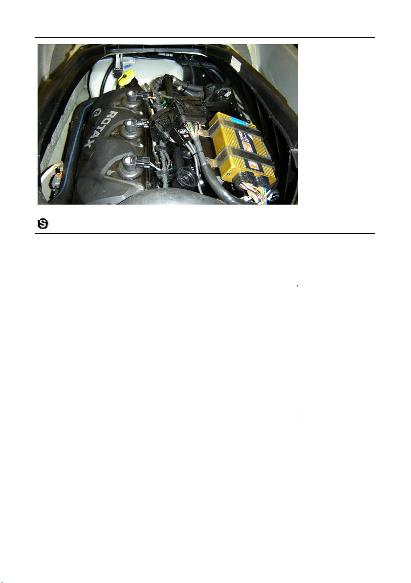
The M400 Marine ECU replaces the factory ECU on top of the engine.
nti
vibration mounts using
the M400 Marine
s
the adaptor loom harness between the M400 ECU and the
onnectors are labelled A and B and are keyed so
lock on the plug
will not slide shut, then the plug is fitted into the wrong connector.
on normally all supplied devices must be connected:
S device plugged into 6 pin socket labelled ‘STC’
IGN4 device plugged into 6 pin socket labelled ‘COIL’ and 4 pin
F device plugged into 12 pin socket labelled ‘DMC’.
the M400 Marine
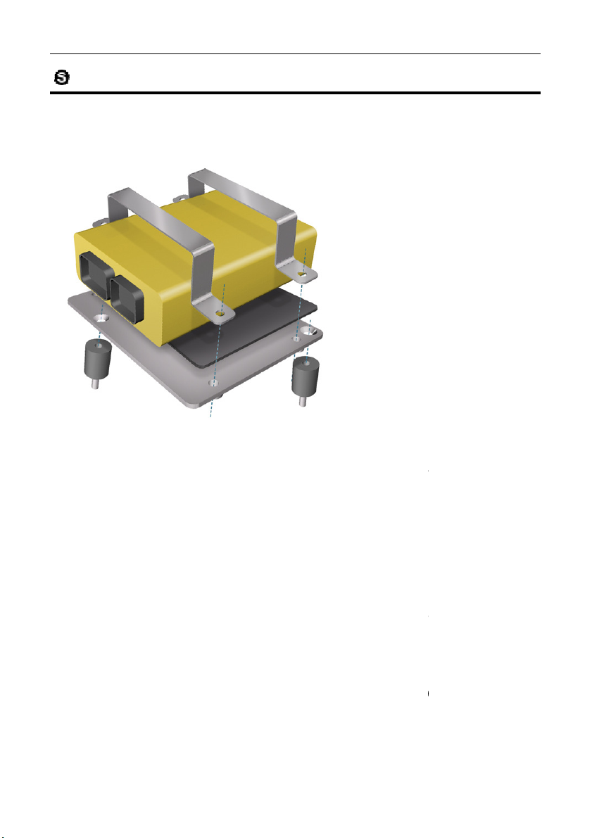
Installation
Remove the factory ECU (four M6 bolts) and screw three a
mounts into three of the mounting holes (see picture).
Screw the Sea-Doo ECU mounting plate to the antiLoctite 243 and M6x10 stainless steel countersunk screws.
Then, place the rubber backing pad on the plate and secure
ECU with the Mounting brackets using four M6x16 stainless
and four M6 stainless steel spring washers.
Finally, connect
factory wiring harness.
Note – the Sea-Doo c
that only the correct plug can be inserted. If the slide-
For the ECU to functi
• STC-
•
socket labelled ‘IGN’.
• DMC-
15
-vibration
teel cap screws
These devices can all be secured by zip-ties.
Page 23
16 Sea-Doo 2004 – 2009 Installation
in ECU is compatible with all RXP, RXPX, RXT, and
RXTX models from 2004 to 2009. However there are numerous harness
2009 mode
different M400 configuration files (Base Maps). If the incorrect
configuration file is loaded, the PWC may operate incorrectly or have limited
The three configuration file versions are designated 2004, 2006
2004 Configuration files match original ECU part numbers:
ginal ECU part numbers
rt numbers
Doo functions including dashboard alerts, the Sea
In ECU requires M400 firmware version 3.52P or higher.
Configuration File
The Sea-Doo PWC Plug-
MoTeC
differences between 2004-2005, 2006, and 2007requires
dashboard functions.
•
420664942, 420664947.
• 2006 Configuration files match ori
420664946
• 2007 Configuration files match original ECU pa
420665789, 420665861
To mimic all original SeaDoo PWC Plug-
ls. Each of these
and 2007.
:
: 420665785,
-
Page 24
MoTeC Sea-Doo 2004 – 2009 Installation
In ECU closely mimics the standard OEM operation. However,
to draw your attention to some operational differences
The M400 Marine ECU engine control functionality is the same as the
standard factory ECU; all normal operations of the PWC are possible, with the
Instrument cluster and mimic
to CAN) data adaptor; the
messages from the ECU, and then transmits
custom data set are provided
prevent engine damage the following dash alarms and rev limits are
These alarms and rev limits are similar to the factory settings.
PWC Operational Differences
The PWC PlugMoTeC would like
when a PWC Plug-In ECU is installed.
ECU Operation
exception of Learner Key Mode and Knock Sensing.
Instrument Cluster Operation
The M400 Marine ECU will control the Sea-Doo
the original factory dash operation.
The ECU controls the dash via the STC (Serial
STC receives serial RS232
messages to the instrument cluster.
The serial RS232 transmit settings and the CAN
in the Base Map and should not be changed.
To
provided:
17
CAN
Sensor Value Dash Alarm
Fuel Tank Level < 10% capacity Yes
Battery Voltage <11.6 V or >15.2 V Yes
Engine
Temperature
Exhaust
Temperature
Oil Pressure No Oil Pressure
Note:
110°C Yes
110°C Yes
Yes
and RPM > 3300
Rev Limit
None
None
4000 rpm
4000 rpm
4000 rpm
Page 25

18 Sea-Doo 2004 – 2009 Installation
Ignition Lanyard with an
immobiliser function to power up the craft. If the Ignition Lanyard is inserted,
pressing the Start/Stop Button on the left handlebar will start and stop the
In ECU solution still uses the
Lanyard but without the immobiliser function. It follows the same strategy as
Power is continuously applied to the ECU while the Lanyard is connected.
Tuning adjustments, log downloads, and ECU configuration file
stopped for longer than 4 seconds, the
M400 Marine ECU sounds the warning beeper in repeated bursts of 4
he Ignition Lanyard.
use an encoded Ignition Lanyard which
In installation does not include the immobiliser function
for example by
or later
the PWC shows stalling behaviour when the throttle is closed suddenly, it
may help to reset the throttle stop screw for a higher base idle RPM setting.
proof cover and is very
. The screw can be very carefully
risk of breakage), and replaced with an M5
%) in the Sensors list, or press ‘V’
Wind in the stop screw until the throttle position reads just over zero.
Power Control Strategy
The standard Sea-Doo RXP, RXP-X and RXT use an
engine.
The installation of the PWC Plug-
the 2007 model Sea-Doo crafts:
•
may all be performed without interruption.
• If the engine is not started, or is
short pulses.
• Power is removed from the ECU only by removing t
Security
The Sea-Doo RXP, RXP-X and RXT
is paired with the factory ECU.
MoTeC
Ignition
downloads
The PWC Plugimportant to secure the craft when not in use
IGN4 device from the wiring harness.
removing the
Idle Stepper Motor Setting (V3.52P
If
The standard throttle stop screw has a tampersecurely glued to the throttle body with loctite
removed (warning M5 lock nut.
To reset a newly installed stop screw
• Connect to the ECU Manager program on a PC.
• Observe the Throttle Position (TP
for the Sensor View screen.
•
• Wind back until exactly zero is shown.
set screw with
. It is
)
Page 26

MoTeC Sea-Doo 2004 – 2009 Installation
to achieve 1850 RPM idle on the ski
TP HI and TP LO settings should not be changed, regardless of where
stock fuel pump draws a small amount of current, the situation may
arise with higher fuel pressures or alternate pumps where the current draw is
If this occurs a reduction in fuel pressure may be evident when t
If the fuel pressure is raised with the stock fuel pump it may be necessary to
add an external Fuel Pump Relay to the loom, to accommodate higher pump
is fitted with a higher current draw, again
it may be necessary necessary to add an external Fuel Pump Relay to the
To set the new idle stop position
• Wind in the stop screw an additional 1.5 turns.
• Altered this setting as required
the water, once the engine has been warmed up.
Note:
the stop screw is positioned.
Fuel Pump current
While the
more than the Adaptor Loom is designed for.
senses over-current and stops fuel pump operation.
current.
Alternatively, if a replacement pump
loom, to accommodate higher pump current.
19
in
he ECU
Page 27
20 Sea-Doo 2010 Installation
In ECU is available with the M800
Sea-Doo 2010 Installation
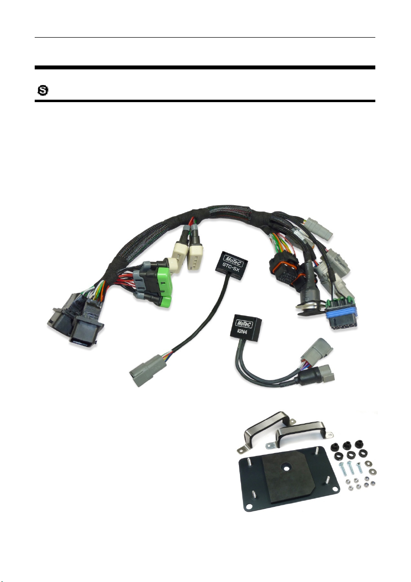
System
ECU
• M400 Marine ECU
Installation Set
• 1 x Adaptor Loom
• 1 x STC-SX (Sea-Doo 2010 Serial to CAN module)
• 1 x IGN4 Ignition Module
MoTeC
Mounting Set
• 1 x Sea-Doo 2010 ECU Mounting Plate
• 2 x ECU mounting brackets
• 3 x Anti-vibration mounts
• Mounting bolts and screws
• 1 x Rubber backing pad.
On request the Sea-Doo PWC PlugECU.
Marine
Page 28
MoTeC Sea-Doo 2010 Installation
es the factory ECU on top of the engine.
assemble the
Installation
The M400 Marine ECU replac
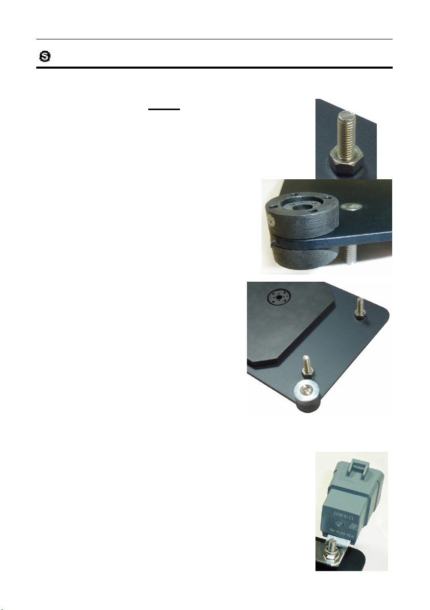
Remove the factory ECU (three T25 Torx screws) and presupplied mounting plate before the M400 ECU is fitted:
• Screw 4 supplied M6 Stainless nuts on the studs
protruding from the top of the mounting plate.
These serve as captive spacers. (see right)
• Invert the plate and ensure that the 3
rubber rings are seated on the rubber
bushes which are fed from the top side
of the plate. (see picture at right)
• Place the plate with rubber inserts
over the plastic mounting bracket
on the PWC.
• Firmly screw 2 x 6mm cap screws
with washers in the lower 2
positions, and 1 x countersunk
screw without washer in the central
position. Do not over tighten.
• Ensure that the rubber mat with
hole is mounted over the centre
countersunk screw.
• Fit the waterproof relay to the top right screw post
which protrudes from the mounting plate.
• Fit the M400 ECU and place the 2 stainless steel
brackets onto the 4 screw posts, after first fitting
the rubber trim strips to the underside of the
brackets.
• Secure the brackets (and relay) with 4 x M6
washers and 4 x M6 Nylock nuts.
21
Page 29

22 Sea-Doo 2010 Installation
first, Plug B into the stock wiring
Ensure that all supplied devices are connected: M400, STC
These devices can all be secured by zip
the M400 ECU MUST have
firmware version 3.52P or later loaded
BEFORE this Adaptor Loom is powered
d the firmware you
should unplug the IGN4 device and remove
all three of the injector/ignition fuses ( #7, 8,
and 9) from Fuse Box 1, and THEN load the
the M400 ECU should have the
relevant start file installed before the IGN4
ice and Injector/Ignition fuses are re
• Now plug in the Adaptor Loom –
harness, then Plug A.
• Next plug the M400 ECU into the Adaptor Loom.
•
IGN4, Relay.
Warning –
MoTeC
-SX,
-ties.
up. If you have not loade
3.52P firmware.
Warning –
dev
installed.
-
Page 30

MoTeC Sea-Doo 2010 Installation
in ECU is compatible with all RX
2009 models in that they use a
different stock ECU which includes Electronic Throttle Control (Drive
and also offer Brake and Suspension options on varying models. Both the
and the 2010 Adaptor Looms
2009 Adaptor Looms.
Configuration files match original ECU part numbers:
Doo functions including dashboard alerts, the Sea
In ECU requires M400 firmware version 3.52P or higher.
Configuration File
23
The Sea-Doo 2010 PWC Plugfrom 2010. These models differ from 2004-
ECU and the harness connector are different
are not interchangeable with the 2004-
• 2010
420664942, 420664947.
To mimic all original SeaDoo PWC Plug-
TX models
-by-Wire)
-
Page 31

24 Sea-Doo 2010 Installation
In ECU closely mimics the standard OEM operation. However,
MoTeC would like to draw your attention to some operational differences
less complex than
only one mode is supported. The handlebar Mode
This craft depends heavily upon CAN bus communication for correct
operation. Both the Instrument Cluster and Brake System (see below) use
transmits and receives
Data Set 1.
as Brake System or Instrument
If for any reason these systems do not operate correctly, the configuration file
BR system works in conjunction with the Brake Lever, ECU and
Instrument Cluster to determine how the brake will operate. The interaction is
Custom Data Set
BR unit is not satisfied with data received from the othe
components, the Instrument Cluster will illuminate the red IBR warning light
must be shut down and restarted before the
IBR system will be fully functional: Remove the Lanyard, wait 10
start the engine.
trument cluster and mimic
to CAN) data adaptor; the
re
PWC Operational Differences
The PWC Plug-
when a PWC Plug-In ECU is installed.
ECU Operation
MoTeC
The M400 Marine ECU engine control functionality is
standard factory ECU;
switching does not operate as in the stock craft.
STC-SX Device
CAN data for critical decisions. The M400 ECU
relevant data via the STC-SX device using Custom
account should this table be changed
Cluster malfunction may result.
and the STC-SX device should be checked first.
iBR Brake System Operation
The i
complex and not user-adjustable. On no account should
1 be changed as Brake system malfunction may result.
If for any reason the i
and the brake system will no longer operate.
In this situation the craft
the
On no
r
seconds, then re-install the Lanyard and re-
Instrument Cluster Operation
The M400 Marine ECU will control the Sea-Doo Ins
the original factory dash operation.
The ECU controls the dash via the STC-SX (Serial
STC-SX receives CAN messages from the ECU, and then
messages to the instrument cluster.
-transmits CAN
Page 32

MoTeC Sea-Doo 2010 Installation
custom data set are provided
set in the dashboard.
The M400 provides relevant information (engine temperature, etc.) and the
shboard raises alarms when required. For this reason all dash alarms will
Strategy
use an Ignition Lanyard with an
A cumbersome start procedure is
required where the Start Button must be pressed before the Lanyard is
beep indicates that the Jet Ski will start.
In ECU solution does not have these requirements. Once the
d is inserted, the Start/Stop button will work at any time. No double
Power is continuously applied to the ECU while the Lanyard is connected.
ds, and ECU configuration file downloads
by removing the Ignition Lanyard.
The Lanyard
ing the engine.
UTC cable
SX device which communicates with
the M400 Marine ECU via CAN at 500kBits/Sec. To connect the system to a
PC using a MoTeC UTC cable requires that the ECU Manager
Launch the ECU Manager program with the PWC powered off.
pulldown, select 500 kbit, and press
The main screen will now show ‘CAN data rate: 500k’ in the lower left
most MoTeC devices uses 1mBit/s as the default CAN speed,
25
The CAN transmit settings and the CAN
Base Map and should not be changed.
The dash alarms are not user-adjustable – they are pre-
da
operate identically to the stock ECU.
Power Control and Engine Start
The standard Sea-Doo 2010 models
immobiliser function to power up the craft.
inserted, then a doubleThe PWC Plug-
Lanyar
beep indication is given by the dash.
Power control follows a different strategy:
•
Tuning adjustments, log downloa
may all be performed without interruption.
• Power is removed from the ECU only
• There is no automated power-down function.
always be removed immediately after stopp
in the
-
should
Connecting to a PC with MoTeC
The Sea-Doo 2010 models use an STC-
PC software
has the CAN communications speed set to 500kBit/S:
•
• On the menu bar select Tools / Options.
• Click on the Communication tab.
• Click on the CAN data rate
•
side.
• Turn on the PWC and proceed.
Note –
whereas many OEM devices use 500kbit/s.
OK.
Page 33

26 Hydrospace S4 Installation
In ECU is available with the M800
Hydrospace S4 Installation
System
ECU
• M400 Marine ECU
Installation Set
• 1 x Adaptor Loom
• 1 x Bosch Ignition Module 200
MoTeC
Mounting Set
• 1 x ECU mounting bracket
• Mounting bolts and screws
• 1 x Rubber backing pad.
• 1 x Mounting plate drill template
On request the Hydrospace PWC PlugMarine ECU.
Page 34

MoTeC Hydrospace S4 Installation 27
Installation
The M400 Marine ECU replaces the factory ECU on a mounting plate beside
the engine.
Remove the factory ECU (3 x M4 bolts) and drill 6 holes into the existing
mounting plate using the mounting plate template. The template is supplied
on a 1:1 scale and can also be downloaded from motec.com.au (CDS13044-A
Hydrospace S4 Mounting Plate Template).
Fit the supplied Ignition Module to the mounting plate.
Note: This module generates significant heat and requires the use of
dielectric grease between the module and mounting plate to ensure proper
heat transfer. Firm fixing of the mounting bolts is also necessary for proper
heat transfer.
Then, place the rubber backing pad on the plate and secure the M400 Marine
ECU with the Mounting bracket using two M6x16 stainless steel cap screws
and two M6 Nylock nuts.
Finally, connect the adaptor loom harness between the M400 ECU and the
factory wiring harness.
The entire assembly can now be lowered into position beside the engine, and
fixed into place with two M6 lock nuts.
Page 35

28 Hydrospace S4 Installation MoTeC
Configuration File
The Hydrospace S4 PWC Plug-in ECU is compatible with all known versions
of the S4 model. The stock S4 model can be operated with numerous boost
levels. A number of configuration files are available with different ECU boost
control strategies, See Base Maps
PWC Operational Differences
The M400 Marine ECU engine control functionality is the same as the
standard factory ECU; all normal operations of the PWC are possible.
MoTeC has added a launch control function using the blue button on the left
side handlebar (see Launch Mode Button). Once optimised by the tuner this
allows for precise and powerful launch performance.
Instrument Cluster Operation
The standard Hydrospace does not include an instrument cluster, MoTeC has
added provision in the Adaptor Loom for an SLM (Shift Light Module). This
can be controlled from the M400 and offers many advantages. It includes
LMA - Launch Mode Assist –, a visual alert system to optimise launch
performance in a racing environment. The supplied Configuration files have
this feature already included.
Power Control Strategy
The Hydrospace S4 uses an ignition lanyard which powers up the craft. With
the lanyard inserted, pressing the start button on the left side handlebar will
start the engine, and either pressing the red button or removing the lanyard
will stop the engine.
Note: the lanyard should always be removed when the engine is stopped to
avoid flattening the battery.
Page 36

MoTeC Hydrospace S4 Installation 29
Launch Mode Button
The existing left handlebar includes an unused blue push button which
MoTeC has designated for Launch Mode. Full throttle can be applied prior to
a race start to build up turbo boost, whilst limiting RPM to 2250. When the
blue button is released, full power is delivered very quickly resulting in rapid
acceleration.
The original blue button is wired through a temperature switch. This switch is
mounted in the exhaust manifold prior to the turbo and will trip at 70 °C,which
would disable the Launch Mode function. This is impractical for race
conditions.
To ensure that Launch Mode is available at all times, install a bypass plug to
short circuit the two pins of the temperature switch connector (same
connector as a Bosch injector).
Page 37

30 Software Installation MoTeC
Software Installation
PC Recommendations
MoTeC recommends a dedicated laptop for your PWC car with the following
specifications:
• 32 bit operating system: Windows XP, Vista or Windows7
• Screen size: 1024 x 768
• Processor speed: 1-2 GHz Pentium
• 2 GB RAM
• 256 MB graphics card
• 2 USB ports
• Ethernet port
Most current laptops will meet the specifications above and this will ensure all
MoTeC software will run on it.
ECU Manager Software (V3.52P or later)
To install ECU Manager Software
• Go to the MoTeC website at www.motec.com and navigate to
downloads/software/latestreleases
- OR -
Locate the Manager software on the MoTeC Resource Disc.
• Save the selected file in your preferred location (for example desktop).
• When downloading is finished, double click on the file and select run.
• Follow the instructions on the InstallShield Wizard.
• To start the program after installation, click on the new Manager icon
on the desktop or click Start > All Programs > MoTeC > M400 M600
M800.
Updating ECU Manager Software
Software updates are made available to give access to the latest features.
Download the latest software version from the website and follow the software
installation instructions to update to the new version.
Page 38

MoTeC Software Installation 31
Connecting the ECU to a PC
The PC communicates with the ECU via the CAN bus and connects to the
USB port on the PC.
This requires a MoTeC UTC (USB to CAN) device. The UTC plugs into the
CAN connector provided on the adaptor loom (5 pin connector) and includes a
standard USB cable to connect to the PC.
Note: Seadoo 2010 models have on-board CAN operating at 500kBit/Sec. To
communicate with a PC the ECU Manager Software must be set to the same
speed (see page 25 for details).
i2 Data Analysis Software
i2 data analysis software is used to analyse the logged data that has been
recorded by the ECU. A combination of graphs, gauges and reports can be
analysed simultaneously. The i2 environment can be customised to specific
user requirements.
The software can be downloaded for free from the website.
To install the i2 software
• Go to the MoTeC website at www.motec.com and navigate to
downloads/software/latestreleases
- OR -
Locate the software on the MoTeC Resource Disc.
• Save the selected file in your preferred location (for example desktop).
• When downloading is finished, double click on the file and select run.
• Follow the instructions on the InstallShield Wizard.
• To start the program after installation, click on the new i2 icon on the
desktop or click Start > All Programs > MoTeC > i2 Standard.
There are two levels of analysis functionality available; i2 Standard which is
included, and i2 Pro which requires the optional Pro Analysis upgrade.
See Upgrades for more information.
Page 39

32 Data Logging MoTeC
Data Logging
To take full advantage of the possibilities of the system, data logging can
provide you with valuable knowledge about the performance and reliability of
the engine and craft. The PWC Plug-In ECU systems have the data logging
option enabled for a free evaluation period of the first 8 hours of engine
running time. After this, the Data Logging upgrade is required. See Upgrades.
In the Base Map, a logging configuration is supplied. This configuration will
log diagnostic channels needed for trouble shooting and will allow for 5 to 15
minutes of logging.
To download the log file
Ensure you have ECU Manager software installed.
The M400 Marine ECU must stay powered while downloading the data. In
most instances the log file can be downloaded within the normal ECU shut
down period. However, for very large files it might be necessary to
manually power up the ECU. See the relevant Power Control Strategy
section for more information.
1. Connect the ECU to the PC. See Connecting the ECU to a PC.
2. Open ECU Manager software.
3. On the Utilities menu, click Get Logged Data.
4. Click Yes to confirm you would like to clear the logging memory.
5. Click OK when prompted for vehicle details.
6. The next screen contains three tabs: Events, Venue and Vehicle.
The details on the events tab are essential; the other two tabs are
optional.
Tip: It is good practice to fill in all relevant details as this will be your
reference to the circumstances under which this file was recorded
when you refer to this file in the future,
7. Enter a Vehicle ID to identify your PWC.
Important:
There are two files created; one with extension .ldx and one with extension
.ld. The .ldx file is smaller than 1 KB (<1000 B), while the .ld file is much
larger. If you would like somebody else to look at your log file, please make
sure you provide the .ld file.
The default location for the files is C:MoTeC/Logged Data.
Tip: The log files are named using a time stamp. When selecting the log files
using i2 (see next section), all details you have entered will be listed. This is
often the easiest way to select the required file.
Page 40

MoTeC Data Logging 33
To select the log file - using i2
Ensure you have i2 data analysis software installed.
1. Open i2 Data analysis software and open a Circuit project.
2. Double click on the file you would like to view.
All details you entered when downloading the logged data will be
listed in the middle window.
Tip: To get started with using i2 to analyse your own logged data,
there are extensive help files included in the software. You can also
download seminar notes on the use of i2 from the MoTeC website.
See How to Get More Information.
To send a log file by email
1. On the File menu, click Open Log File.
2. Right click on the file you would like to send.
Note: This file must be open, indicated with a green tick on the file
icon.
3. Click Copy, open your email recipient (e.g. MS Outlook) and paste the
file into the email
- OR -
Click Send To and then click Mail Recipient.
Change the Logging Settings
The provided logging configuration in the Base Map will provide 5 to 15
minutes of logging. If you would like to increase this time, you need to reduce
the number of channels logged, or reduce the logging rate for the logged
channels.
To change the logging configuration
See the relevant Power Control Strategy section to ensure the M400
Marine ECU stays powered while downloading the data.
1. Connect the ECU to the PC. See Connecting the ECU to a PC.
2. Open ECU Manager software.
3. On the File menu, click Save As and choose a new file name.
This will save the changes you are going to make in a new file and
prevent accidentally overwriting the standard Base Map.
Tip: It is good practice to add an incrementing number to the file
name to keep track of the files you are creating.
4. On the File menu, click Edit Comments.
Tip: Filling in comments will help to identify the file when you refer to
it in the future.
Page 41

34 Data Logging MoTeC
5. On the Adjust menu, click Data Logging Setup.
6. Click Engine Sensors and select the sensor you would like to
change.
7. To include the sensor in the logging, enter a value for the Samples
per Second at which you would like to log this sensor
- ORTo exclude the sensor from the logging, enter 0 for the Samples per
Second.
As you are changing the settings a new logging time will be
calculated. This is shown in the bar under the logging parameters.
8. Press N to browse through all the pages with the other available
logging settings until finished.
A maximum of 64 items can be selected for logging.
9. On the File menu, click Save.
10. On the File menu, click Send File to ECU.
Tips:
• While changing the logging settings, actual logging will be disabled until
you disconnect the ECU from the PC. To guarantee that logging will
resume MoTeC suggests that after you have finalised your logging
settings in ECU Manager you select another table, for example a fuel or
spark map. For a quick way to do this, press F5 to display the fuel map.
• Ensure that a maximum of 64 channels are selected for logging.
If more channels are selected, only the first 64 selected channels are
logged.
Page 42

MoTeC Options to Expand the System 35
Options to Expand the System
GPS
The M400 Marine ECU can receive GPS data via RS232 communication,
which allows wiring MoTeC's 5 Hz GPS-G1 (#41300) direct into the ECU's
existing RS232 receive port. This GPS feature is an extremely useful addition
for PWCs because conventional speed detection methods are inaccurate.
The following GPS based channels are available: Speed, Time, Longitude,
Latitude, Altitude, Satellites, Quality, HDOP (Range Error).
For wiring information see the relevant calibration notes in the appendices.
To configure the GPS in ECU Manager software
1. On the Adjust menu, click General Setup.
2. Click Communications and then RS232 Telemetry Setup.
3. Enter Telemetry Baud Rate 19201.
4. Enter Telemetry Data Set 0 to turn the dataset Off.
Upgrades
The M400 Marine ECU comes with a range of features as standard and
several options available as upgrades to customise and grow your system.
These additional features are activated through a simple password acquired
from your MoTeC dealer, at any time when you need it.
Data Logging
To take full advantage of the possibilities of the system, data logging can
provide you with valuable knowledge about the performance and reliability of
the engine and craft.
The PWC Plug-In ECU systems have the data logging option enabled for a
free evaluation period of the first 8 hours of engine running time. After this, the
Data Logging Upgrade is required which allows recording of all ECU data to
the 500 kB internal logging memory.
Wideband Lambda
Additional tuning of all PWC Plug-In ECU installations is best performed with
a Lambda sensor.
The PWC Plug-In ECU systems have the Lambda option enabled for a free
evaluation period of the first 8 hours of engine running time. After this, the
Page 43

36 Options to Expand the System MoTeC
Lambda Upgrade is required which allows the use of a single on-board
wideband Lambda controller for NTK UEGO or Bosch LSU sensors.
PWC exhaust systems use a cooling water jacket to surround the exhaust
manifold and some of the exhaust muffler and associated tubing. The exhaust
gases pass through a water canister which can charge the exhaust manifold
with water vapour. This water vapour can drastically shorten the life-span of
Lambda sensors, sometimes to less than one hour.
Important: We do not advise the fitting of Lambda sensors unless you are
prepared to replace them frequently.
For wiring information see the relevant Pin List in the appendices.
Suitable mounting positions for Lambda sensors are shown in the appendix
Lambda Sensor Installation.
Pro Analysis
This upgrade provides access to advanced i2 Pro data analysis software with
multiple graph overlays, X-Y plots, advanced maths functions, synchronised
video (manual alignment), and flexible layouts to accommodate virtually any
user preference. Requires the Data Logging upgrade.
You can try the i2 Pro software by downloading it from the website
www.motec.com.au and use the included demo file.
Page 44

MoTeC Appendices 37
Appendices
Specifications
Outputs
• 4 x Injector outputs—high or low ohm
• 4 x Ignition outputs
• 8 x Auxiliary outputs—for functions such as camshaft control, drive by
wire throttle, boost control, nitrous injection, idle speed stepper motor and
many more.
Inputs
• 8 x Analogue voltage inputs—fully configurable including custom
calibrations, e.g. to use for:
o jet outlet pressure
o jet intake pressure
o steering position
o lateral G force
• 6 x Analogue temperature inputs— fully configurable including custom
calibrations, e.g. to use for:
o multiple configuration maps
o extra air temperature
o extra water temperatures
o exhaust temperature
• 1 x Wideband Lambda input—for Lambda measurement and control.
• 4 x Digital/speed inputs—for use with OEM factory speed paddle wheel
and function activation e.g. launch control, anti lag and dual RPM limit.
Communications
• 1 x CAN
• 1 x RS232— e.g. to use with GPS
The 5 Hz MoTeC GPS-G1 can be wired direct to the M400 Marine ECU
for logging of accurate speed and position.
Physical
• Case size 147 x 105 x 40 mm
• Weight 900 gram
• 1 x 34 pin and 1 x 26 pin waterproof connector with gold plated contacts.
Page 45

38 Appendices
Do not refer to the pin numbers moulded into the back of the Yamaha
connectors as some of the numbers are repeated on each connector.
Yamaha
Connectors
M400 Marine ECU Connector
Looking into the connector on the ECU
Yamaha Factory Connector
MoTeC
Looking into the connector on the ECU
Note:
Page 46

MoTeC Appendices
12 V Switched (ECU
Optional: Lambda
Optional: 8 V to SKM Module
5 V Sensor Supply
0 V Sensor Supply
8 V to CAN Connector
5 V Sensor Supply
Optional: Lambda
0 V for CAN and KTC devices
Injector Cylinder 1
Injector Cylinder 2
Injector Cylinder 4
Injector Cylinder 3
Not Available in M400
Not Available in M400
in M400,M600
Not Available in M400,M600
Optional: Available for Knock
Knock Window
Ignition Cylinder 1
Ignition Cylinder 2
Pin List by Function
M400 Pin Yamaha Pin Function
Power
39
VBAT A26 R1, R13, R19, P7,
P21, K6
GND A10 S10, S15, S18, R20 ECU Earth
GND A11 S10, S15, S18, R20 ECU Earth
8V ENG A12 not used
5V ENG A02 R18, R23, R24
Power
0V ENG B16 R14, R15, R8, R9
8V AUX A13 C3
5V AUX A09 P25, P26, B11 via
4K7
0V AUX B15 not used
0V COMM B14 C1, K1
Output
Inj1 A19 S6
Inj2 A20 S7
Inj3 A21 S31
Power
Ground
Relay)
Heater Supply
, Optional: GPS
, Optional: GPS
Sensor or GPS
Inj4 A22 S32
Inj5 A27 not used
Inj6 A28 not used
Inj7 A29 not used Not Available
Inj8 A30 not used
Ign1 A03 S33
Ign2 A04 S34
Module SKM -
Page 47

40 Appendices MoTeC
M400 Pin Yamaha Pin Function
Ign3 A05 S8 Ignition Cylinder 4
Ign4 A06 S9 Ignition Cylinder 3
Ign5 A07 not used Not Available in M400
Ign6 A08 not used Not Available in M400
1
Aux1
Aux2 1 A01 S26 Drive By Wire Motor +
Aux3 1 A23 S29 Fuel Pump Relay
Aux4 1 A24 P20 ECU Relay
Aux5 A31 not used Optional: Lambda Sensor Heater
Aux6 1 A32 S28 ETV Relay
Aux7 A33 not used
Aux8 1 A34 Not an output – table is used for
A18 R26 Drive By Wire Motor -
External Power-up Wire
Control
Oil Pressure Dashboard Alarm
indication.
Inputs
Ref B01 P8 Ref Sensor (Magnetic)
Sync B02 P3 Sync Sensor (Hall)
AT1 2 B03 P15 Air Temperature
AT2 2 B04 P23 Engine Temperature
2,5
AT3
B05 P13 Muffler Water Temperature
AT4 2 B06 S27 Oil Pressure Switch
AT5 2 B07 S12 Engine Temperature Switch
3,5
AT6
B19 P18 Reverse Switch
AV1 A14 R16 Throttle Position
AV2 A15 R17 Throttle Position 2
AV3 A16 R10 Throttle Position Driver 2
AV4 A17 R11 Throttle Position Driver
AV5 5 A25 P17 Steering Lock Pressure Sensor
Page 48

MoTeC Appendices 41
M400 Pin Yamaha Pin Function
AV6 2 B20 P16 Manifold Pressure Sensor
AV7 5 B21 P19 Handlebar Switch
5
AV8
B22 S11 Handlebar Switch
DIG1 B08 Speed 4
DIG2 5 B09 S2 Handlebar Switch
DIG3 1 B10 S20 Ignition Switch
DIG4 B11 P5, A9 via 4K7 Tip over Switch
La1S B25 not used Optional: Available for Lambda
Sensor
La1P B26 not used Optional: Available for Lambda
Sensor
La2S B12 not used Optional: Available for Knock
Module SKM - Knock Signal
La2P B13 not used
Communications
RS232-TX B17 P24 Handlebar Switch
RS232-RX B18 not used Optional: Available for GPS
Receive Data
CAN-LO B24 C4, K4 CAN line to KTC dash adaptor
CAN-HI B23 C5, K5 CAN line to KTC dash adaptor
0V COMM B14 C1, K1 0 V for CAN and KTC devices
Additional Yamaha Loom Pins
Unused S01, S03, S04, S05,
S13, S14, S16, S17,
S19, S21, S22, S23,
S24, S25, S30
Unused R02, R03, R04,
R05, R06, R07,
R12, R22, R25
4
Page 49

42 Appendices MoTeC
M400 Pin Yamaha Pin Function
Unused P02, P04, P06,
P09, P10, P11,
P12, P14, P22
K-Line (K2) R21 K-Line to KTC adaptor pin K2
Knock P1 Optionally: Available for Knock
Module SKM - Knock Input
1 – 5: See Calibration and Wiring Notes
Page 50

MoTeC Appendices
with the function and
Parameters
Output Mode 0
PWM/Switched 1
Output Mode 0
Frequency 10
Minimum Duty Cycle 0
Maximum Duty Cycle 100
Hysteresis 0
PWM/Switched 0
Output Mode 0
Frequency
Minimum Duty Cycle 0
Maximum Duty Cycle 100
Hysteresis 0
Logic Polarity 1
Calibration and Wiring Notes
Note 1 – Calibration Functions
The following pins are calibrated in the Base Maps
parameters as mentioned in the table.
43
M400 Pin Yamaha Pin Function
Aux1 A18 R26 5: Drive by wire
Aux2 A01 S26 0: Off
Aux3 A23 S29 101: Fuel Pump Delay 2.0
Polarity 0
Aux4
Aux6
Aux8 A34 3: Aux Table
A24
A32
P20
S28
3: Aux Table
Polarity 0
Polarity 0
10
DIG3 B10 S20 8: Ignition Switch
Delay 0.0
Latch 0
Page 51

44 Appendices
For the following pins the calibration table is available in the provided
Reverse Switch and Dual RPM Limit
include a Rev Limiting function which is activated
this switch malfunctions,
rpm may be
the wiring and fitment
onnector P18 to pin B19 on the
Input Functions
approx
AT6 should
disable the Dual RPM Limit function
Function
Note 2 – Calibration Tables
Maps.
M400 Pin Yamaha Pin Function
AT1 B03 P15 Air Temperature
AT2 B04 P23 Engine Temperature
AT3 B05 P13 Muffler Water Temperature
AT4 B06 S27 Oil Pressure Switch
AT5 B07 S12 Engine Temperature Switch
AV6 B20 P16 Manifold Pressure Sensor
MoTeC
Base
Note 3 - AT6
The Yamaha Base Maps
when the Reverse Switch is engaged on the craft. If
or if the switch is not installed, the Dual RPM limit of 4000
permanently engaged.
If your ski appears to limit revs at 4000 rpm, first check
of the Reverse Switch and then check the operation.
The Reverse Switch is wired via harness c
M400 Marine ECU.
In ECU Manager software, this appears in Digital
(AT6).
To check the Reverse Switch operation
1. On the View menu, click Raw Input Values.
2. Click the AT tab and check the AT6 value.
For normal operation (non-reverse), AT6 should be
0.03 volts. When the reverse switch is engaged,
approximately 4.95 volts.
If this is not the case, you can
the Base Map.
To disable the Dual RPM Limit
1. On the Adjust menu, click Digital Input Functions.
2. Click Sw In 6 (AT6) - Dual RPM and then click
3. Enter 0 (zero).
4. Press R to restart the ECU, or power cycle the ECU.
as Sw In 6
imately
be
from
.
Page 52

MoTeC Appendices
The PWC speed sensor is wired directly to the dashboard. To acquire this
information, a separate wire is required from the factory harness to M400
includes a speed
For more accurate speed measurements, MoTeC recommends the use of a
into the EC
essential for PWC
operation. These wires can be allocated to other functions as required.
Note 4 - Speed
Marine ECU pin Dig1 (B8). The supplied Base Map
calibration which can be enabled if this sensor is wired.
GPS system.
MoTeC's 5 Hz GPS-G1 (#41300) can be wired directly
receive port.
GPS wiring
M400 Pin GPS Pin Function
0V AUX B15 1
Bat –
RS232-RX B18 2 RS232 GPS Data
N/C 3
5V AUX
5V ENG
A09
A02
4 5 V
Note 5 – Available Wiring
These pins are wired into the adaptor loom, but are not
45
U's RS232
M400 Pin Yamaha Pin
AT6 B19 P18
AV5 A25 P17
AV7 B21 P19
AV8 B22 S11
DIG2 B09 S2
Page 53

46 Appendices
Kawasaki
Connectors
M400 Marine ECU Connector
Looking into the connector on the ECU
Kawasaki Factory Connector
MoTeC
Looking at front of the connectors
Page 54

MoTeC Appendices
V Switched (System Relay)
Optional: Lambda heater supply
Optional: 8 V to SKM Module
Optional: GPS Power
Optional: GPS Power
ensor
0 V for CAN and KTC devices
Not Available in M400,M600
Not Available in M400,M600
Optional: Available for Knock Module
Coil 1 Trigger to BIM200 Module
Coil 2 Trigger to BIM200 Module
Pin List by Function
M400 Pin Kawasaki Pin Function
Power
VBAT A26 K17,D06 12
GND A10 J05,C04 ECU Earth
GND A11 J14,F01 ECU Earth
8V ENG A12 not used
5V ENG A02 K09,F08 5 V Sensor Supply,
0V ENG B16 K05,K15,K32 0 V Sensor Supply
8V AUX A13 E03 8 V to CAN Connector
5V AUX A09 not used 5 V Sensor Supply,
0V AUX B15 not used Optional: Lambda S
0V COMM B14 D01,E01
Outputs
Inj1 A19 J08 Injector Cylinder 1
47
or GPS Ground
Inj2 A20 J17 Injector Cylinder 2
Inj3 A21 J13 Injector Cylinder 4
Inj4 A22 J04 Injector Cylinder 3
Inj5 A27 not used Not Available in M400
Inj6 A28 not used Not Available in M400
Inj7 A29 not used
Inj8 A30 not used
Ign1 A03 C07
Ign2 A04 C02
Ign3 A05 not used
Ign4 A06 not used
SKM - Knock Window
Page 55

48 Appendices MoTeC
M400 Pin Kawasaki Pin Function
Ign5 A07 not used Not Available in M400
Ign6 A08 not used Not Available in M400
1
Aux1
Aux2 1 A01 J06 Main (ECU) Relay
Aux3 1 A23 F04 System Relay via KPE Device
Aux4 1 A24 J15 Fuel Pump Relay
Aux5 1 A31 K01 Idle Stepper Motor
Aux6 1 A32 K18 used for Idle Stepper Motor
Aux7 1 A33 K02 used for Idle Stepper Motor
Aux8 1 A34 K19 used for Idle Stepper Motor
Inputs
Ref B01 K22 Ref Sensor (Magnetic)
Sync B02 K07 Sync Sensor (Hall)
2
AT1
AT2 1 B04 K20 Engine Stop Button
AT3 2 B05 K03 Oil Pressure Switch
AT4 B06 not used
AT5 B07 not used
AT6 B19 not used
AV1 A14 K30 Throttle Position
AV2 2 A15 K23 Manifold Pressure Sensor
A18 not used Optional: Lambda Sensor Heater Control
B03 K28 Air Temperature
AV3 2 A16 K11,F07 Engine Temperature
AV4 2 A17 K13,F06 Oil Temperature
AV5 2 A25 K08,F05 Intercooler Water Temperature
AV6 B20 not used
AV7 B21 not used
AV8 B22 not used
DIG1 B08 K26 Tip over Switch
DIG2 B09 K21 Steering Lock Switch
Page 56

MoTeC Appendices 49
M400 Pin Kawasaki Pin Function
DIG3 B10 not used
DIG4 B11 not used
La1S B25 not used Optional: Available for Lambda Sensor
La1P B26 not used Optional: Available for Lambda Sensor
La2S B12 not used Optional: Available for Knock Module
SKM - Knock Signal
La2P B13 not used
Communications
RS232-TX B17 not used
RS232-RX B18 not used Optional: Available for GPS Receive Data
CAN-LO B24 D04,E04 CAN line to KTC dash adaptor
CAN-HI B23 D05,E05 CAN line to KTC dash adaptor
0V COMM B14 D01,E01 0 V for CAN and KTC devices
Additional Kawasaki Loom Pins
J01,J03,J07,J1
Unused
Unused
J09 BIM200 Module drive for Coil 1 C06
J16 BIM200 Module drive for Coil 2 C01
J02 System Relay Drive from KPE F03
J11 Key trigger to KPE F02
K-Line K2 K29 K-Line to KTC adaptor pin D02
1-3: See Calibration and Wiring Notes
0,J12,J18
K04,K06,K10,
K12,K14,K16,
K24,K25,K27,
K31,K33,K34
3
Page 57

50 Appendices
with the function and
Parameters
On Time 20
0
Mode 0
On Time 15
Polarity 0
Output Mode 0
Delay 2.0
Polarity 0
Output Mode 0
Max Step Rate 200
Polarity 0
Logic Polarity
Low RPM Limit 100
RPM Rise Rate 0
Ignition Retard 30
Calibration and Wiring Notes
Note 1 – Calibration Functions
The following pins are calibrated in the Base Maps
parameters as mentioned in the table.
MoTeC
M400 Pin Kawasaki Pin Function
Aux1 A18 not used 9: Lambda Heater
Aux2 A01 J06 118: Power Hold
Aux3 A23 F04 118: Power Hold
Aux4 A24 J15 101: Fuel Pump
Aux5 A31 K01 8: Idle Stepper
Aux6 A32 K18 0: Off
Aux7 A33 K02 0: Off
Aux8 A34 K19 0: Off
AT2 B04 K20 4: Dual RPM limit
DIG1 B08 K26 29: Monitor
Polarity
Output
0
Page 58

MoTeC Appendices
For the following pins the calibration table is available in the provided
Intercooler Water Temperature
For accurate speed measurements, MoTeC recommends the use of a GPS
into the ECU
Note 2 – Calibration Tables
Maps.
M400 Pin Kawasaki Pin Function
AT1 B03 K28 Air Temperature
AT3 B05 K03 Oil Pressure Switch
AV2 A15 K23 Manifold Pressure Sensor
AV3 A16 K11, F07 Engine Temperature
AV4 A17 K13, F06 Oil Temperature
51
Base
AV5 A25 K08, F05
Note 3 – Speed
system.
MoTeC's 5 Hz GPS-G1 (#41300) can be wired directly
receive port.
GPS wiring
M400 Pin GPS Pin Function
0V AUX B15 1
RS232-RX B18 2 RS232 GPS Data
N/C 3
5V AUX
5V ENG
A09
A02
4 5 V
Bat –
's RS232
Page 59

52 Appendices
To test if all outputs are correctly wired to the relevant injectors and coils, the
you would like to use this function in a Kawasaki installation
control pins must be physically grounded, by removing them from the M400
de of the plug until it clicks
pin locking plate from Connector A (white plastic inserts
range 20AWG), and A24
from the rear of the connector using firm pressure.
dual white tabs on the top side of the plug until it clicks
the outputs,
re
Output Test Function
MoTeC
ECU Manager software has an output test function available
menu, click Test Outputs).
If
ECU plugs and jumping to ground.
1. Unplug the M400 ECU connectors.
2. Press the single white tab on the undersi
to unlock the
in the plug),
3. Extract pins A01 (white 18AWG), A23 (o
(yellow 20AWG)
4. Press the
lock the pin locking plate,
5. Re-insert the ECU plugs into the M400.
6. When ready to power up the ECU and test
three wires to ground.
Once testing is completed, reverse the above procedure to
wires into the M400 connector.
(on the Utilities
, three relay
to
jumper all
-insert the three
Page 60

MoTeC Appendices
Sea-Doo 2004-2009
Connectors
M400 Marine ECU Connector
Looking into the connector on the ECU
Sea-Doo Factory Connectors
RXP/ RXPX/ RXT A Connector (top view)
53
RXP/ RXPX/ RXT B Connector (top view)
Looking into the plugs on the adapter loom
Page 61

54 Appendices
V Switched (System Relay)
Optional: Lambda Heater Supply
V to SKM Module
V to CAN Connector
Optional: Lambda Sensor or GPS
0 V for CAN and STC devices
Not Available in M400
Not Available in M400
Not Available in M400, M600
Pin List by Function
M400 Pin Sea-Doo Pin Function
Power
VBAT A26 B11,F06,K01 12
GND A10 B1,B2,B20,B32,
C05
GND A11 B22,B35,B39,B
41
8V ENG A12 not used Optional: 8
5V ENG A02 A39,A40 5 V Sensor Supply
0V ENG B16 A19, A20, A21,
A23, A25, A26,
A27, A28, K12
8V AUX A13 E03 8
5V AUX A09 not used 5 V Sensor Supply
0V AUX B15 not used
0V
COMM
Outputs
Inj1 A19 A15 Injector Cylinder 1
Inj2 A20 A33 Injector Cylinder 2
Inj3 A21 A14 Injector Cylinder 3
Inj4 A22 not used
Inj5 A27 not used
Inj6 A28 not used
Inj7 A29 not used
B14 E01,F01
ECU Earth
ECU Earth
Optional: GPS Power
0 V Sensor Supply
Optional: GPS Power
Ground
MoTeC
Page 62

MoTeC Appendices 55
M400 Pin Sea-Doo Pin Function
Inj8 A30 not used Not Available in M400, M600.
Optional: Available for Knock Module
SKM - Knock Window
Ign1 A03 D01 Coil 1 Trigger to IGN4 Module
Ign2 A04 D02 Coil 2 Trigger to IGN4 Module
Ign3 A05 D03 Coil 3 Trigger to IGN4 Module
Ign4 A06 not used
Ign5 A07 not used Not Available in M400
Ign6 A08 not used Not Available in M400
1
Aux1
Aux2
Aux3
Aux4
Aux5
Aux6
Aux7
Aux8
1
1
1
1
1
1
1
A18 not used Optional: Lambda Sensor Heater
Control
A01 B29 Fuel Pump
A23 A13,B18 Oil Shutoff Valve (2004) , not used
(2006), Buzzer (2007)
A24 B31 Starter Solenoid
A31 A36 Idle Stepper Motor
A32 A35 used for Idle Stepper Motor
A33 A38 used for Idle Stepper Motor
A34 A37 used for Idle Stepper Motor
Inputs
Ref B01 A05 Ref Sensor (Magnetic)
Sync B02 A34 Sync Sensor (Hall)
2
AT1
AT2
AT3
AT4
2
2
2
B03 A07 Air Temperature
B04 A11 Engine Temperature
B05 A10 Exhaust Water Temp Sensor
B06 B34,A31 Crankcase Pressure Switch (2004),
not used (2006), VTS Trim Level
(2007)
2
AT5
B07 A06 Oil Pressure Switch
Page 63

56 Appendices MoTeC
M400 Pin Sea-Doo Pin Function
1
AT6
2
AV1
2
AV2
2
AV3
2
AV4
AV5 A25 not used
AV6 B20 not used
AV7 B21 not used
AV8 B22 not used
1
DIG1
1
DIG2
1
DIG3
1
DIG4
La1S B25 not used Optional: Available for Lambda
La1P B26 not used Optional: Available for Lambda
La2S B12 not used Optional: Available for Knock Module
La2P B13 not used
Communications
RS232-TX B17 F03 Serial line to STC dash adaptor F03
RS232-RX B18 not used Optional: Available for GPS Receive
CAN-LO B24 E04 Used only for CAN Comms to PC
CAN-HI B23 E05 Used only for CAN Comms to PC
0V COMM B14 E01,F01 0 V for CAN and STC devices
B19 B19 Start/Stop Button
A14 A24 Throttle Position
A15 A12 Manifold Pressure Sensor
A16 B08,K06 External Water Temperature (2007)
A17 B13 Fuel Tank Level (2007)
B08 K08 Speed via DMCF Device K08
B09 B09 Tip over Switch
B10 B07,B30 VTS Trim Up Button (2007)
B11 B23,B33 VTS Trim Down Button (2007)
Sensor
Sensor
SKM - Knock Signal
Data
@1000 kbit/s
@1000 kbit/s
Page 64

MoTeC Appendices 57
M400 Pin Sea-Doo Pin Function
Additional Sea-Doo Loom Pins
Unused A02, A03, A04,
A08, A16, A17,
A18, A22, A30,
A32
Unused B03, B04, B05,
B10, B12, B14,
B15, B16, B21,
B25, B36, B37,
B40
Coil 2 A01 Coil2 Drive from IGN4 Module C02
Coil 3 A29 Coil3 Drive from IGN4 Module C03
Coil 1 A41 Coil1 Drive from IGN4 Module C01
Knock
Sensor
Water
Speed
ECU
Power
Relay
Lanyard B26 Lanyard Sense - not used as Lanyard
Dash CAN
Hi
A09 Optional: Knock Sensor signal to SKM
B06 Water Speed Signal to DMCF K05
B17 Relay Drive - not used as Lanyard
B27 STC CAN to Dash @250 kbit/s F04
Knock Module
(2007)
controls ECU power
controls ECU power
Dash CAN
Lo
DESS
Immo
K-Line B24 K-Line - not used
1-3: See Calibration and Wiring Notes
B28 STC CAN to Dash @250 kbit/s F05
B38 DESS Comms - not used
Page 65

58 Appendices
with the function and
Parameters
Polarity 0
Output Mode 0
PWM/Switched 0
Output Mode 0
Polarity 0
Frequency 200
Minimum Duty Cycle 0
Maximum Duty Cycle 100
Hysteresis 0
Hold Time 0
Delay to On Time 0.0
Include Diag Errors 0
Logic Polarity 0
Output Mode 0
Power Hold 0
On Alert 1
Selection 40
Logic Polarity 0
Output Mode 0
Flash Rate 0.0
Max Step Rate 200
Polarity 0
Calibration and Wiring Notes
Note 1 – Calibration Functions
The following pins are calibrated in the Base Maps
parameters as mentioned in the table.
MoTeC
M400 Pin Sea-Doo Pin Function
Aux1 A18 not used 9: Lambda Heater
Aux2 A01 B29 101: Fuel Pump Delay 3.0
Aux3 A23 A13,B18 (2004)
3: Aux Table
Aux3 A23 A13,B18 (2006)
0: Off
Aux3 A23 A13,B18 (2007)
107: Driver
Warning
Aux4 A24 B31 115: Status
Aux5 A31 A36 8: Idle Stepper
Aux6 A32 A35 0: Off
Aux7 A33 A38 0: Off
Flash 0
Page 66

MoTeC Appendices
Parameters
Polarity 1
Measurement Type 3
Calibration 1116
Active Edge 0
Window 0
Noise Increment 0
Noise Limit 0
Logic Polarity 0
Polarity 0
Polarity 0
For the following pins the calibration table is available in the provided
Crankcase Pressure Switch
External Water Temperature
59
M400 Pin Sea-Doo Pin Function
Aux8 A34 A37 0: Off
AT6 B19 B19 31: Start/Stop
Switch
DIG1 B08 K08 1: Speed Measure
DIG2 B09 B09 8: Ignition Switch
DIG3 B10 B07,B30 29: Monitor
DIG4 B11 B23,B33 29: Monitor
Note 2 – Calibration Tables
Maps.
Noise
Delay 1.0
Latch 0
Base
M400 Pin Sea-Doo Pin Function
AT1 B03 A07 Air Temperature
AT2 B04 A11 Engine Temperature
AT3 B05 A10 Exhaust Water Temp Sensor
AT4 B06 B34,A31 (2004)
(2007) VTS Trim Level
AT5 B07 A06 Oil Pressure Switch
AV1 A14 A24 Throttle Position
AV2 A15 A12 Manifold Pressure Sensor
AV3 A16 B08,K06 (2007)
AV4 A17 B13 (2007) Fuel Tank Level
Page 67

60 Appendices
For accurate speed measurements, MoTeC recommends the use of a GPS
into the ECU
Water Speed
can be reconfigured
etup Custom Data Sets
and then click
box.
OK
oo dashboards show a maximum speed of 70 MPH or 113 km/h.
Doo
Note 3 – Speed
system.
MoTeC's 5 Hz GPS-G1 (#41300) can be wired directly
receive port.
GPS wiring
M400 Pin GPS Pin Function
0V AUX B15 1
Bat –
RS232-RX B18 2 RS232 GPS Data
N/C 3
5V AUX
5V ENG
A09
A02
4 5 V
GPS Speed Display on dashes.
Late model Sea-Doo crafts (2007+) transmit the
ECU to the dash (Custom Dataset 1, Item 4).
With a GPS Receiver connected, this dash display
GPS Speed display.
MoTeC
's RS232
from the M400
as a
To setup the display for GPS Speed
1. On the Adjust menu, click General Setup
2. Click Communications and then click S
3. Select Item 4 – Left Ground Speed (LG Spd)
Change.
4. Select the Show Non-Sensor Channels check
5. Enter GPS Speed in the Search Text box and click
6. Click OK to leave the Custom Data Set screen.
7. Save the altered configuration with a new name.
Note: Sea-D
This limitation is unaltered with the installation of the Sea-
.
Adaptor Loom.
.
Page 68

MoTeC Appendices
Sea-Doo 2010
Connectors
M400 Marine ECU Connector
Looking into the connector on the ECU
Sea-Doo Factory Connectors
RXTX 2010 A Connector (top view)
RXTX 2010 B Connector (top view)
Looking into the plugs on the adapter loom
61
Page 69

62 Appendices
12 V Switched (System Relay)
Lambda Heater Supply
, IGN4 Earth
, Fuel Pump Relay Earth
Optional: 8 V to SKM Module
V to CAN Connector
Lambda Sensor Ground
0 V for CAN and STC devices
Not Available in M400
M400
Not Available in M400, M600
Not Available in M400,
Optional: Available for Knock Module
Knock Window
Pin List by Function
M400 Pin Sea-Doo Pin Function
Power
VBAT A26 B-M4, S06, L05
GND A10 B-F2, B-L1, B-
M2, C05
GND A11 B-M3, R85,R87 ECU Earth
8V ENG A12 not used
5V ENG A02 A-K4, A-B4, B-
J3, B-K1
0V ENG B16 B-K3, B-H3, B-
B3, A-A2, A-C4,
A-D4, A-H2, AJ2, A-K2, A-J3,
A-J4
8V AUX A13 E03 8
5V AUX A09 A-F4 5 V Sensor Supply
0V AUX B15 L01
0V
COMM
Outputs
Inj1 A19 A-B3 Injector Cylinder 1
Inj2 A20 A-K1 Injector Cylinder 2
Inj3 A21 A-J1 Injector Cylinder 3
Inj4 A22 not used
Inj5 A27 not used
Inj6 A28 not used Not Available in
Inj7 A29 not used
Inj8 A30 not used
B14 A-G2, E01,S01
ECU Earth
5 V Sensor Supply
Optional: GPS Power
0 V Sensor Supply
MoTeC
M600.
SKM -
Page 70

MoTeC Appendices 63
M400 Pin Sea-Doo Pin Function
Ign1 A03 D03 Coil 1 Trigger to IGN4 Module
Ign2 A04 D02 Coil 2 Trigger to IGN4 Module
Ign3 A05 D01 Coil 3 Trigger to IGN4 Module
Ign4 A06 not used
Ign5 A07 not used Not Available in M400
Ign6 A08 not used Not Available in M400
1
Aux1
Aux2
Aux3
Aux4
Aux5
Aux6
Aux7
Aux8
1
1
1
1
A18 A-L2 Throttle Motor (-)
A01 A-L1 Throttle Motor (+)
A23 B-E4, B-H2 System Relay Drive
A24 B-L4 Starter Solenoid
A31 L04 Lambda Heater Control
A32 R86 Fuel Pump Relay
A33 not used
A34 not used
Inputs
Ref B01 A-H1 Ref Sensor (Magnetic)
Sync B02 A-E2 Sync Sensor (Hall)
2
AT1
AT2
AT3
AT4
AT5
AT6
AV1
AV2
AV3
AV4
2
2
2
1
2
2
2
2
B03 A-H3 Air Temperature
B04 A-A1 Engine Temperature
B05 A-H4 Exhaust Water Temp Sensor
B06 Not used
B07 A-E3 Oil Pressure Switch
B19 B-D1 Start/Stop Button
A14 A-F3 Throttle Position
A15 A-G4 Manifold Pressure Sensor
A16 A-K3 Throttle Position 2
A17 B-A3 Throttle Lever
AV5 A25 B-E1 Throttle Lever 2
Page 71

64 Appendices MoTeC
M400 Pin Sea-Doo Pin Function
AV6 B20 not used
AV7 B21 not used
AV8 B22 not used
1
DIG1
1
DIG2
1
DIG3
1
DIG4
La1S B25 L02 Lambda Sensor Sense Voltage
La1P B26 L08 Lambda Sensor Pump Current
La2S B12 not used Optional: Available for Knock Module
La2P B13 not used
Communications
RS232-TX B17 not used
RS232-RX B18 not used Optional: Available for GPS Receive
CAN-LO B24 E04, S04, B-C2 CAN Comms @500 kbit/s
CAN-HI B23 E05, S05, B-C1 CAN Comms @500 kbit/s
0V COMM B14 A-G2, E01,S01 0 V for CAN and STC devices
B08 not used
B09 A-G1 Tip over Switch
B10 not used
B11 B-H1 OTAS Switch
SKM - Knock Signal
Data
Additional Sea-Doo Loom Pins
Unused A-A3,A-A4,A-B1,A-B2,A-C1,A-C2,A-
D1,A-D2,A-D3,A-E1,A-E4,A-F1,A-F2,AG3,A-L3,A-L4,A-M3
Unused B-A1,B-A4,B-B1,B-B4,B-C3,B-C4,B-
D2,B-D3,B-D4,B-E2,B-E3,B-F1,B-F3,BF4,B-G1,B-G2,B-G3,B-G4,B-H4,B-J1,BJ2,B-J4,B-K2,B-K4,B-L2,B-L3
Coil 1 A-M4 Coil1 Drive from IGN4 Module C03
Coil 2 A-M2 Coil2 Drive from IGN4 Module C02
Page 72

MoTeC Appendices 65
M400 Pin Sea-Doo Pin Function
Coil 3 A-M1 Coil3 Drive from IGN4 Module C01
Knock
Sensor
Fuel
Pump
Relay
ECU
Power
Relay
Lanyard B-E4 Lanyard Sense - not used as Lanyard
DESS
Immo
K-Line B-A2 K-Line - not used
1-3: See Calibration and Wiring Notes
A-C3 Optional: Knock Sensor signal to SKM
Knock Module
B-M1 Output of Fuel Pump Relay
B-H2 Relay Drive - not used as Lanyard
controls ECU power
controls ECU power
B-B2 DESS Comms - not used
Page 73

66 Appendices
with the function and
Parameters
Selection 40
Logic Polarity 0
Output Mode 0
Flash Rate 0.0
Lambda Sensor 1
Polarity 1
Output Mode 1
Polarity 1
Stop Delay 0.2
Lo Level 5.2
Hi Level 5.3
For the following pins the calibration table is available in the provided
Calibration and Wiring Notes
Note 1 – Calibration Functions
The following pins are calibrated in the Base Maps
parameters as mentioned in the table.
MoTeC
M400 Pin Sea-Doo Pin Function
Aux1 A18 A-L2 5: Drive by Wire
Aux2 A01 A-L1 0: Off
Aux3 A23 B-E4, B-H2 0: Off
Aux4 A24 B-L4 115: Status
Flash 0
Aux5 A31 L04 9: Lambda Heater
Aux6 A32 R86 101: Fuel Pump Delay 3.0
Aux7 A33 0: Off
Aux8 A34 0: Off
AT6 B19 B-D1 31: Start/Stop
Switch
Setup -
Setup -
Note 2 – Calibration Tables
Maps.
M400 Pin Sea-Doo Pin Function
AT1 B03 A-H3 Air Temperature
AT2 B04 A-A1 Engine Temperature
Base
Page 74

MoTeC Appendices
oo 2010 models incorporate GPS speed within the stock dash. This is
available to the M400 on the CAN communications bus and compares in
AT3 B05 A-H4 Exhaust Water Temp Sensor
AT5 B07 A-E3 Oil Pressure Switch
AV1 A14 A-F3 Throttle Position
AV2 A15 A-G4 Manifold Pressure Sensor
AV3 A16 A-K3 Throttle Position 2
AV4 A17 B-A3 Throttle Lever
AV5 A25 B-E1 Throttle Lever 2
Note 3 – Speed
Sea-D
accuracy to MoTeC’s own GPS devices.
67
Page 75

68 Appendices MoTeC
Hydrospace S4
Connectors
M400 Marine ECU Connector
Looking into the connector on the ECU
Hydrospace Factory Connector
Looking into the connector on the ECU.
Page 76

MoTeC Appendices 69
Pin List by Function
M400 Pin Hydro S4 Pin Function
Power
VBAT A26 C08,C09 12 V Switched (System Relay), Lambda
Heater Supply
GND A10 C02,D04 ECU Earth, Ignition Module Earth
GND A11 C21 ECU Earth
8V ENG A12 not used Optional: 8 V to SKM Module
5V ENG A02 C30 5 V Sensor Supply, Optional: GPS Power
0V ENG B16 G01,M01 0 V Sensor Supply
8V AUX A13 E03 8 V to CAN Connector
5V AUX A09 not used 5 V Sensor Supply, Optional: GPS Power
0V AUX B15 C06 0 V Sensor Supply
0V COMM B14 E01,F01 0 V for CAN and SLM devices
Outputs
Inj1 A19 C31 Injector Cylinder 1
Inj2 A20 C32 Injector Cylinder 2
Inj3 A21 not used Injector Cylinder 4
Inj4 A22 not used Injector Cylinder 3
Inj5 A27 not used Not Available in M400
Inj6 A28 not used Not Available in M400
Inj7 A29 not used Not Available in M400,M600
Inj8 A30 not used Not Available in M400,M600
Optional: Available for Knock Module
SKM - Knock Window
Ign1 A03 D07 Coil 1 Trigger to BIM200 Module
Ign2 A04 D02 Coil 2 Trigger to BIM200 Module
Ign3 A05 not used
Ign4 A06 not used
Page 77

70 Appendices MoTeC
M400 Pin Hydro S4 Pin Function
Ign5 A07 not used Not Available in M400
Ign6 A08 not used Not Available in M400
1
Aux1
Aux2 1 A01 C33 Pop-Off Valve
Aux3 1 A23 C26 Main (ECU) Relay
Aux4 1 A24 C29 Wastegate Solenoid
Aux5 1 A31 C34 Fuel Pump Relay
Aux6 A32 not used
Aux7 A33 not used
Aux8 A34 not used
Inputs
Ref B01 C15 Ref Sensor (Magnetic)
Sync B02 C23 Sync Sensor (Hall)
2
AT1
AT2 2 B04 C13 Engine Temperature
AT3 1 B05 C19 Temp Switch via Blue Handlebar Button
AT4 1 B06 C08 via diode Lanyard Connected / Red Button
AT5 B07 M02 Optional: available for ancillary function
AT6 B19 M03 Optional: available for ancillary function
AV1 2 A14 C12 Throttle Position
AV2 2 A15 C11 Manifold Pressure Sensor
A18 G04 Lambda Sensor Heater Control
B03 C20 Air Temperature
AV3 A16 not used
AV4 A17 not used
AV5 A25 not used
AV6 B20 not used
AV7 B21 not used
AV8 B22 not used
DIG1 B08 not used
DIG2 B09 not used
Page 78

MoTeC Appendices 71
M400 Pin Hydro S4 Pin Function
DIG3 B10 not used
DIG4 B11 not used
La1S B25 G02 Lambda Sensor Vs
La1P B26 G08 Lambda Sensor Ip
La2S B12 not used Optional: Available for Knock Module
SKM - Knock Signal
La2P B13 not used
Communications
RS232-TX B17 not used
RS232-RX B18 not used Optional: Available for GPS Receive Data
CAN-LO B24 E04,F02 CAN line to SLM Shift Light Module
CAN-HI B23 E05,F03 CAN line to SLM Shift Light Module
0V COMM B14 E01,F01 0 V for CAN and SLM devices
Additional Hydrospace Loom Pins
C03,C04,C05,
C16,C17,C18,
C22,C24,C25,
Unused
C01 BIM200 Module drive for Coil 1 D06
C10 BIM200 Module drive for Coil 2 D01
C07 Spare 0 V Signal lead (not used)
1-3: See Calibration and Wiring Notes
C27,C28
3
Page 79

72 Appendices MoTeC
Calibration and Wiring Notes
Note 1 – Calibration Functions
The following pins are calibrated in the Base Maps with the function and
parameters as mentioned in the table.
M400 Pin Hydro S4 Pin Function Parameters
Aux1 A18 G04 9: Lambda Heater Lambda Sensor 1
Aux2 A01 C33 3: Aux Table PWM/Switched 0
Output Mode 0
Polarity 0
Frequency 10
Minimum Duty Cycle 0
Maximum Duty Cycle 100
Hysteresis 0
Aux3 A23 C26 3: Aux Table PWM/Switched 1
Output Mode 0
Polarity 0
Frequency 10
Minimum Duty Cycle 0
Maximum Duty Cycle 100
Hysteresis 0
Aux4 A24 C29 1: Boost Control Frequency 50
Polarity 0
Output Mode 0
Aux5 A31 C34 101: Fuel Pump Delay 0.5
Polarity 0
Output Mode 0
Aux6 A32 0: Off
Aux7 A33 0: Off
Aux8 A34 0: Off
AT3 B05 C19 4: Dual RPM limit
Logic Polarity 0
Low RPM Limit 2400
RPM Rise Rate 0
Ignition Retard 26
Page 80

MoTeC Appendices 73
AT4 B06 C08 via diode 10: Brake
Logic Polarity 1
Source 0
Channel 1
Lo Level 5.1
Hi Level 5.2
Note 2 – Calibration Tables
For the following pins the calibration table is available in the provided Base
Maps.
M400 Pin Hydro S4 Pin Function
AT1 B03 C20 Air Temperature
AT2 B04 C13 Engine Temperature
AV1 A14 C12 Throttle Position
AV2 A15 C11 Manifold Pressure Sensor
Note 3 – Speed
For accurate speed measurements, MoTeC recommends the use of a GPS
system.
MoTeC's 5 Hz GPS-G1 (#41300) can be wired directly into the ECU's RS232
receive port.
GPS wiring
M400 Pin GPS Pin Function
0V AUX B15 1
Bat –
RS232-RX B18 2 RS232 GPS Data
N/C 3
5V AUX
5V ENG
A09
A02
4 5 V
Page 81

74 Appendices
PWC exhaust systems use a cooling water jacket to surround the exhaust
manifold and some of the exhaust muffler and associated tubing. The exhaust
es pass through a water canister which can charge the exhaust manifold
his water vapour can drastically shorten the lifespan of
s unless you are
exhaust manifold.
inboard side of exhaust
Lambda Sensor Installation
gas
with water vapour. T
Lambda sensors, sometimes to less than one hour.
Important: We do not advise the fitting of lambda sensor
prepared to replace them frequently.
Yamaha Lambda Sensor
Suitable sensor mounting position is towards the rear of the
MoTeC
Kawasaki Lambda Sensor
Suitable sensor mounting position is on the
casting on circular flat.
elbow
Page 82

MoTeC Appendices
t rear of exhaust manifold, next to water
2009 only)
t the VTS Trim level from the M
can be reconfigured
y useful feedback whilst
f Lambda is on Aim, the bar graph will be
An Aim error of 0.10 will move the bar to the top or bottom of the
Base Map
Setup Custom Data Sets
and then click
box.
and
oo 2010 models.
Sea-Doo Lambda Sensor (all model years)
Suitable sensor mounting position is a
fitting.
75
Lambda Aim Error Display (Sea-Doo 2007-
Sea-Doo models from 2007-2009 transmi
ECU to the dash (Custom Dataset 1, Item 3).
With the Lambda sensor installed, this dash display
Lambda Aim Error display. This will provide ver
tuning.
The display can be set up, so that i
centred.
gauge.
This function uses the IGN5 table which is included in the
To setup the display for Lambda aim error
1. On the Adjust menu, click General Setup.
2. Click Communications and then
3. Select Item 3 – Trim Level (VTSLev)
4. Select the Show Non-Sensor Channels check
5. Enter Ign Out5 Duty Cycle in the Search Text box
6. Click OK to leave the Custom Data Sets screen.
7. Save the altered configuration file with a new name.
Note – this function is not possible with Sea-D
400
as a
.
.
Change.
click OK.
Page 83

76 Appendices MoTeC
Hydrospace S4 Lambda Sensor
The standard exhaust manifold casting is fitted with a Lambda mounting
position.
Page 84

MoTeC Appendices 77
Base Maps
These are available from the MoTeC website at
www.motec.com/pwcplugin/basemaps.
Page 85

78 Appendices MoTeC
Glossary
MoTeC Devices
ACL Advanced Central Logger
ADL2 Advanced Dash Logger - second generation
ADL3 Advanced Dash Logger - third generation
BR2 Beacon Receiver
BTX Beacon Transmitter
CIM Computer Interface Module
CLS Central Logging System
DBW4 Drive By Wire expander
E816 Input/Output Expander
E888 Input/Output Expander
i2 MoTeC data analysis software, standard version
i2 Pro MoTeC data analysis software, professional version
IEX Ignition Expander
LTC Lambda to CAN module
LTCD Lambda to CAN Dual module
M2R ECU dedicated to run 2 rotor engines
M4 ECU for engines with up to 4 cylinders or up to 2 rotors
M400 ECU for modern engines with up to 4 cylinders or up to 2 rotors
M48 ECU for engines with up to 8 cylinders and 2 rotors
M600 ECU for modern engines with up to 6 cylinders or up to 3 rotors
M800 ECU for modern engines with up to 12 cylinders or up to 4
rotors
M880 ECU for modern engines with up to 12 cylinders or up to 4
rotors
MDC Mitsubishi Diff Controller
MDD Mini Digital Display
MLS ECU dedicated to run Chevrolet LS1 and Lexus/Toyota V8s
PCI cable PC Interface cable
PDM15 Power Distribution Module with 15 outputs
PDM16 Power Distribution Module with 16 outputs
PDM30 Power Distribution Module with 30 outputs
Page 86

MoTeC Appendices 79
PDM32 Power Distribution Module with 32 outputs
PLM Professional Lambda Meter
Plug-In ECU ECU for direct replacement of a factory ECU
RTC Real Time Clock
SDC Subaru Diff Controller
SDL Sport Dash Logger
SGA Strain Gauge Amplifier
SLM Shift Light Module
SUU Software Update Unit
TCM Traction Control Module
VIM Versatile Input Module
Other
Calibration The process of converting an electrical value into a physical
CAN Controller Area Network - communication protocol
CDI Capacitive Discharge Ignition
ECU Engine Control Unit
GPS Global Positioning System
MAF Mass Air Flow
MAP Manifold Absolute Pressure
PID Proportional, Integral and Derivative gain
PWM Pulse Width Modulated.
RPM Revolutions Per Minute
RS232 Recommended Standard 232, communication protocol
RX Receive
TDC Top Dead Centre
TX Transmit
value e.g. Volts into kilometres per hour
Page 87

80 Appendices MoTeC
How to Get More Information
A good place to start is the website at www.motec.com
In the Product area of the website you will find information on engine
management, data acquisition and Lambda measurement.
In the Downloads area of the website you will find:
• Manuals including the general M400 ECU Manual.
• Latest software where you can download i2 Standard data analysis
software, or a trial version of the i2 Pro version.
• Seminar notes from the training seminars MoTeC runs on ECU installation
and tuning and i2 data analysis software.
Forums
Also on the MoTeC website you will find a Forum with a thread dedicated to
PWCs.
Another useful forum is greenhulk.net/forums
Page 88

MoTeC Notes 81
Page 89

82 Notes MoTeC
Page 90

MoTeC Notes 83
Page 91

84 Notes MoTeC
 Loading...