

Motec MVCD1000-x, MVCD1001-x, MC7180N, MD3071A, MD3071A-V Installation Instructions Manual
Mobile Vicinity Scout (MVS)
Installation instructions

2
Mobile Vicinity Scout (MVS)
Installation instructions
IA_MVS-EN
05.2018
Rev. 02
Original instruction
Manufacturer:
Motec GmbH
Oberweyerer Straße 21
65589 Hadamar-Steinbach
GERMANY
Phone: +49 6433 9145-0
Fax: +49 6433 9145-45
motec.info@ametek.com
www.motec-cameras.com
© Copyright 2018 by Motec GmbH
Subject to change without notice.
The document is protected by copyright. It supports the user in the safe and efficient use of the product.
Reprints, translations and reproductions in whatsoever form, including extracts, require written consent from the publisher.

3
Table of contents
1 About these instructions ................................................................................................................................. 7
1.1 Contact .................................................................................................................................................................... 7
1.2 Design features ....................................................................................................................................................... 7
1.3 Target group for these instructions ........................................................................................................................ 7
1.4 Other applicable documents .................................................................................................................................. 8
1.5 Declaration of conformity ....................................................................................................................................... 8
1.6 Guarantee ............................................................................................................................................................... 8
2 Safety ............................................................................................................................................................. 9
2.1 Introduction ............................................................................................................................................................ 9
2.2 Intended use ........................................................................................................................................................... 9
2.3 Non-intended use ................................................................................................................................................... 9
2.4 Predictable misuse .................................................................................................................................................. 9
2.5 Remaining risks ..................................................................................................................................................... 10
2.6 Display of warnings ............................................................................................................................................... 10
2.7 Safety and warning labels on the system components ........................................................................................ 11
2.8 Obligations of operator and target group ............................................................................................................ 11
2.9 Wear personal protective gear ............................................................................................................................. 11
3 System description ........................................................................................................................................ 12
3.1 Package contents .................................................................................................................................................. 13
3.1.1 MVS system .................................................................................................................................................. 13
3.1.2 Service kit ...................................................................................................................................................... 13
3.2 Type signs ............................................................................................................................................................. 14
3.3 Technical Data ...................................................................................................................................................... 14
3.4 Components .......................................................................................................................................................... 14
3.4.1 Video control unit ......................................................................................................................................... 14
3.4.2 Camera .......................................................................................................................................................... 14
3.4.3 Monitor ......................................................................................................................................................... 15
3.4.4 Operator control unit .................................................................................................................................... 15
4 Installation .................................................................................................................................................... 16
4.1 Selecting the best possible installation location .................................................................................................. 16
4.2 Installation of the MVCD control unit ................................................................................................................... 17
4.3 Installation of monitor .......................................................................................................................................... 17
4.4 Laying cables ......................................................................................................................................................... 17
4.4.1 Preparing for laying....................................................................................................................................... 17
4.4.2 Laying cables ................................................................................................................................................. 17
4.5 Electrical connections ........................................................................................................................................... 18
4.5.1 Power supply ................................................................................................................................................ 18
4.5.2 Cameras ........................................................................................................................................................ 18
4.5.3 Monitor ......................................................................................................................................................... 18
4.5.4 MBE1000 operator control unit .................................................................................................................... 18
4.5.5 Control leads/CAN bus connector ................................................................................................................ 18
4.5.6 Connection digram ....................................................................................................................................... 19
5 Operation ..................................................................................................................................................... 20

4
5.1 Switching on the system ....................................................................................................................................... 20
5.1.1 Menu overview ............................................................................................................................................. 21

5
6 Getting started .............................................................................................................................................. 22
6.1 Language selection ............................................................................................................................................... 22
6.2 Basic set 270° or 360° ........................................................................................................................................... 22
6.3 Basic setting of the image mode .......................................................................................................................... 23
6.4 Stitching or Blending basic setting ........................................................................................................................ 23
6.5 Calibration............................................................................................................................................................. 24
6.5.1 Basic setting Calibration marker size ............................................................................................................ 24
6.5.2 Laying out the calibration markers ............................................................................................................... 24
6.5.3 Aligning the 360° system .............................................................................................................................. 25
6.5.4 Aligning the 270° system .............................................................................................................................. 25
6.5.5 Check the position of the calibration markers ............................................................................................. 26
6.5.6 Enter the effective dimensions ..................................................................................................................... 26
6.5.7 Requirements for the calibration ................................................................................................................. 27
6.5.8 Semi-automatic calibration .......................................................................................................................... 27
6.6 Saving the settings ................................................................................................................................................ 28
7 Advanced features ........................................................................................................................................ 29
7.1 Blending zones ...................................................................................................................................................... 29
7.1.1 Stitching ........................................................................................................................................................ 29
7.1.2 Blending ........................................................................................................................................................ 30
7.2 Manual calibration ................................................................................................................................................ 31
7.3 Control lines .......................................................................................................................................................... 33
7.3.1 Introduction .................................................................................................................................................. 33
7.3.2 Requirements ............................................................................................................................................... 33
7.3.3 Configuration ................................................................................................................................................ 34
7.4 Static overlays ....................................................................................................................................................... 35
7.4.1 Introduction .................................................................................................................................................. 35
7.4.2 Configuration ................................................................................................................................................ 35
7.4.3 Delete Overlays ............................................................................................................................................. 37
7.5 Adjusting the vehicle image contour .................................................................................................................... 38
7.5.1 Configuration ................................................................................................................................................ 38
7.5.2 Creating a customised vehicle image ........................................................................................................... 39
7.6 Connecting ultrasonic sensors .............................................................................................................................. 42
7.6.1 Introduction .................................................................................................................................................. 42
7.6.2 Connection and configuration ...................................................................................................................... 43
7.6.3 Configuration ................................................................................................................................................ 43
7.6.4 Editing/deleting sensors ............................................................................................................................... 44
7.6.5 Overlays ........................................................................................................................................................ 45
8 Operating mode ............................................................................................................................................ 46
9 Fault fixing .................................................................................................................................................... 47
9.1 Hardware .............................................................................................................................................................. 47
9.2 Malfunctions during the initial start-up ............................................................................................................... 48
9.3 Malfunctions during operation ............................................................................................................................. 49
9.4 Ultrasonic sensors ................................................................................................................................................. 51
10 Maintenance ................................................................................................................................................. 52
10.1 Cleaning the monitor ............................................................................................................................................ 52
10.2 Cleaning the camera lenses .................................................................................................................................. 52
11 Disposal and environmental protection ......................................................................................................... 52

6
11.1 Disposal of packaging ........................................................................................................................................... 52
11.2 Disposal of the products ....................................................................................................................................... 52
12 Index ............................................................................................................................................................ 53

7
1 About these instructions
Thank you for your confidence in Motec products!
• We develop and manufacture our products with the
greatest of care.
• Our products are constantly being developed; Motec
GmbH reserves the right to make changes to system
components without prior notification.
• If operated in terms with the product’s intended use,
these installation instructions help you to use the
product safely.
• These installation instructions apply only to the product
indicated on the cover sheet.
• We reserve the right to make changes to these
installation instructions based on technical
advancements.
• These installation instructions are part of the scope of
delivery.
• These installation instructions are valid starting from
the date of transport to final disposal. Compliance is
mandatory.
• Therefore, always keep the instalation instructions in a
legible condition and store it in the cockpit. Pass on the
document if you sell the product.
• The operating company must ensure that the
installation instructions are read and understood by all
persons before starting to work on the product.
• The chapter on safety gives an overview about all the
important aspects of safety to ensure optimum
protection of personnel and safe, trouble-free operation
of the product.
• The manufacturer cannot be held liable for damage
resulting from non-compliance with these installation
instructions.
• For all questions on set-up guidelines and interface
documentation, please contact the vehicle
manufacturer directly.
1.1 Contact
If you have any questions about the product, its
commissioning or operation or if the products does not
meet your expectations, please do not hesitate to contact
us.
Motec GmbH
Service
Oberweyerer Str. 21
65589 Hadamar-Steinbach
GERMANY
Phone:
+49 6433 9145-9888
Fax:
+49 6433 9145-9877
E-mail:
motec.service@ametek.com
Internet:
www.motec-cameras.com
1.2 Design features
Various elements of the operating instructions have fixed
design features.
Text
Normal body text
•
Bullet points
1.
Steps
This is the general hazard symbol.
It warns of hazards to life or potential injury.
PLEASE NOTE
The words PLEASE NOTE indicate further information
on the device or its use.
1.3 Target group for these instructions
These installation instructions are aimed at the personnel
of the manufacturers or personnel trained by the
manufacturer and charged with the installation of the
product.
The installation and electrical connection must always be
carried out by appropriately qualified personnel!

8
1.4 Other applicable documents
Compliance with the following applicable documentation
is mandatory:
• Setup guidelines and applicable standards.
• Technical specifications of the vehicle and setup
manufacturer.
• Datasheets and operating instructions for system
components.
• Motec System Bus (MSB 2.0) specification for systems
with CAN communication to the vehicle.
1.5 Declaration of conformity
• As the initial vendor within Europe, we have conducted
an evaluation of conformity for our products in
accordance with EU directives and legal regulations
based on the requirements of the relevant "harmonised
standards".
• You will find the CE mark on the product and also on
the accompanying product documentation.
• We will be happy to provide you with a separate EC
Declaration of Conformity upon request.
1.6 Guarantee
• Please report any guarantee claims to your supplier or
service partner immediately after you discover the fault
or error.
• The guarantee shall be invalidated in all cases in which
no liability claims can be asserted.
• If the system is used improperly or incorrectly, no
liability can be accepted for any damage caused.
• In case of use outside the EU, the user is required to
comply with relevant national requirements.
• If modifications are made to the device, compliance
with the requirements of conformity is no longer
ensured and the warranty becomes void.
• No liability is accepted for damage or malfunctions
which are caused as described below:
• Failure to comply with the instructions.
• Unauthorised modifications to the system.
• Operating errors.
• Failure to carry out maintenance.
• The system must only be repaired, maintained and
configured by qualified personnel in conjunction with
Motec.
• In the event of a fault, contact the supplier or service
partner immediately if it cannot be remedied.
• The information, diagrams and descriptions in these
instructions cannot be used to derive requests to
modify existing supplied systems and components.
• The information in these instructions describes the
characteristics of the product without guaranteeing
them.
• The information, data and instructions set out in these
instructions was up-to-date at the time of printing.
• If using external components such as on-board sat-nav
systems or multi-functional displays, liability claims are
invalidated.
• Motec accepts no liability for different page ratios,
vehicle-related restrictions and related display formats.
For more information, please consult the relevant
operating and installation instructions.

9
2 Safety
2.1 Introduction
This chapter gives an overview of all important safety
aspects to protect personnel, for safe and trouble-free use
of the product from installation through to disposal.
• Failure to comply with the instructions and safety
instructions set out in this manual can lead to
significant risks of personal injury or damage to the
product.
• The product has been designed based on the state-ofthe-art and recognised technical safety guidelines and
standards. The product is safe to use.
2.2 Intended use
• The Motec MVS System is a driver assistance system
can only be operated with a its system limits.
• The device provides the driver with a 270°/360° allround view from a bird's-eye perspective. Images
provided by the wide angle cameras that are installed
on both sides, the front and rear of the
vehicle/machinery capture the surroundings.
In order to obtain the desired images, the MVS System
must be installed and operated compliant with these
operating instructions.
The driver/operator shall be responsible for the safe
operation of the vehicle at all times. This obligation
applies in particular if personnel remain in the danger
zone of the vehicle/machinery.
2.3 Non-intended use
Any use of other than that described in the
Chapter"Intended use" on page 9and any use beyond that
shall be deemed non-intended.
• The manufacturer accepts no liability for damage
caused as a result. The risk is borne solely by the
user/operating company.
• It is prohibited to change the system in any shape or
form.
• It is prohibited to operate the system by bypassing the
safety devices.
• It is prohibited to use components which are defect and
therefore jeopardise the safety of the system!
• The Motec MVS is not suitable for the protection of
persons in the sense of the applicable standards and
guidelines for machines and vehicles (Machinery
Directive 2006/42 / EU, DIN EN ISO 13849 and ISO
26262).
2.4 Predictable misuse
The following points describe predictable misuse of the
product:
• Work or operation carried out by unskilled or
insufficiently skilled personnel.
• Improper installation.
• Failure to comply with operational data and
maintenance intervals.
• Operation without or with damaged components, which
are intended for the safety of the persons and the
system.
10
2.5 Remaining risks
Folge
Remaining risks can occur under the following
circumstances:
• If the system is not used as intended, if the system is
modified or altered improperly.
• If the system is operated improperly by untrained or
unskilled personnel.
• If the system is cleaned, serviced or maintained
improperly and/or if non-compliant with scheduled
service intervals.
The following remaining risks should also be taken into
consideration:
• Electrical current during installation or cleaning can
lead to injury or death. Work on the electrical system
must only be carried out by qualified electricians while
the system is disconnected!
• Working in close quarters poses the risk of bumps and
crush injuries and cuts from sharp corners and edges.
• Improper handling can damage the bodywork,
components or cables.
• Welding work may not be carried out on tank
components!
• Failure to comply with the installation guidelines and
technical specifications of the vehicle and
manufacturer.
• Tree branches or other objects above the cameras are
not recorded! In this case, the use of the rear-view
mirrors or the assistance of a banksman is mandatory!
• The higher an object from the ground, the more this
object is displayed on the monitor as bending outward.
This representation, which is not true to scale, must be
taken into account by the driver.
• The display in the monitor is true to scale only on the
footprint of the vehicle and only in the undistorted
mode.
• The image quality decreases with corresponding
environmental conditions: In this case, a banksman
must be available during the manoeuvring of the
vehicle.
• However, the reality may slightly deviate from this
composed image. Objects outside the image cones are
not captured.
2.6 Display of warnings
In these instructions, warnings are shown in the form of
warning pictograms. The warnings must be observed in
order to avoid accidents, injury or damage to property.
The warnings are introduced by keywords which express
the extent of the risk.
The following key words and symbols are used within these
instructions.
This is the general hazard symbol.
It warns of hazards to life or potential injury.
DANGER
The keyword DANGER is used for an immediate risk.
Failure to observe will lead to serious injury or death.
WARNING
The keyword WARNING is used for a potential risk.
Failure to observe could lead to serious injury or death.
CAUTION
The keyword CAUTION is used for a potential risk.
Failure to observe could lead to minor to moderate
injuries.
CAREFUL
The keyword CAREFUL indicates possible damage to
property. Failure to observe could lead to damage to the
product.

11
2.7 Safety and warning labels on the system
components
Information and symbols, such as safety labels and signs,
attached to the system components must be observed.
These safety labels and signs must not be removed and
must be kept in legible at all times.
2.8 Obligations of operator and target group
• Never operate or continue to operate system
components with safety-relevant faults.
• Prior to their use, check all system components for
obvious damage and observe their functions in order to
detect potential faults.
• Defects that are detrimental to safety must be rectified
before the system is placed in operation again.
Otherwise, the system must not be used!
• The correct installation and proper operation of the
system must be monitored by the operating company.
• The operator must ensure that the installer, the
electrician and the user have read and understood the
instructions.
• The operator and user are therefore responsible for
ensuring correct use of the system.
• Prior to driving, the driver must proceed with a visual
inspection and a functional test before using the
system.
• Before the installation of the system components and
during their operation, compliance with the applicable
manufacturer's information and safety instructions of
the vehicle is mandatory.
• When using the system, compliance with the
recommended installation guidelines and
manufacturer's interface documentation is mandatory.
2.9 Wear personal protective gear
• When working on the system components or on the
vehicle, the necessary personal protective equipment
must be worn.
• Failure to wear personal protective gear can lead to
serious injury or death.
• Make sure that there are no unauthorised personnel in
the hazardous area.
• For further information, the operator provides the
current, locally relevant guidelines for the occupational
safety and accident prevention.
12
3 System description
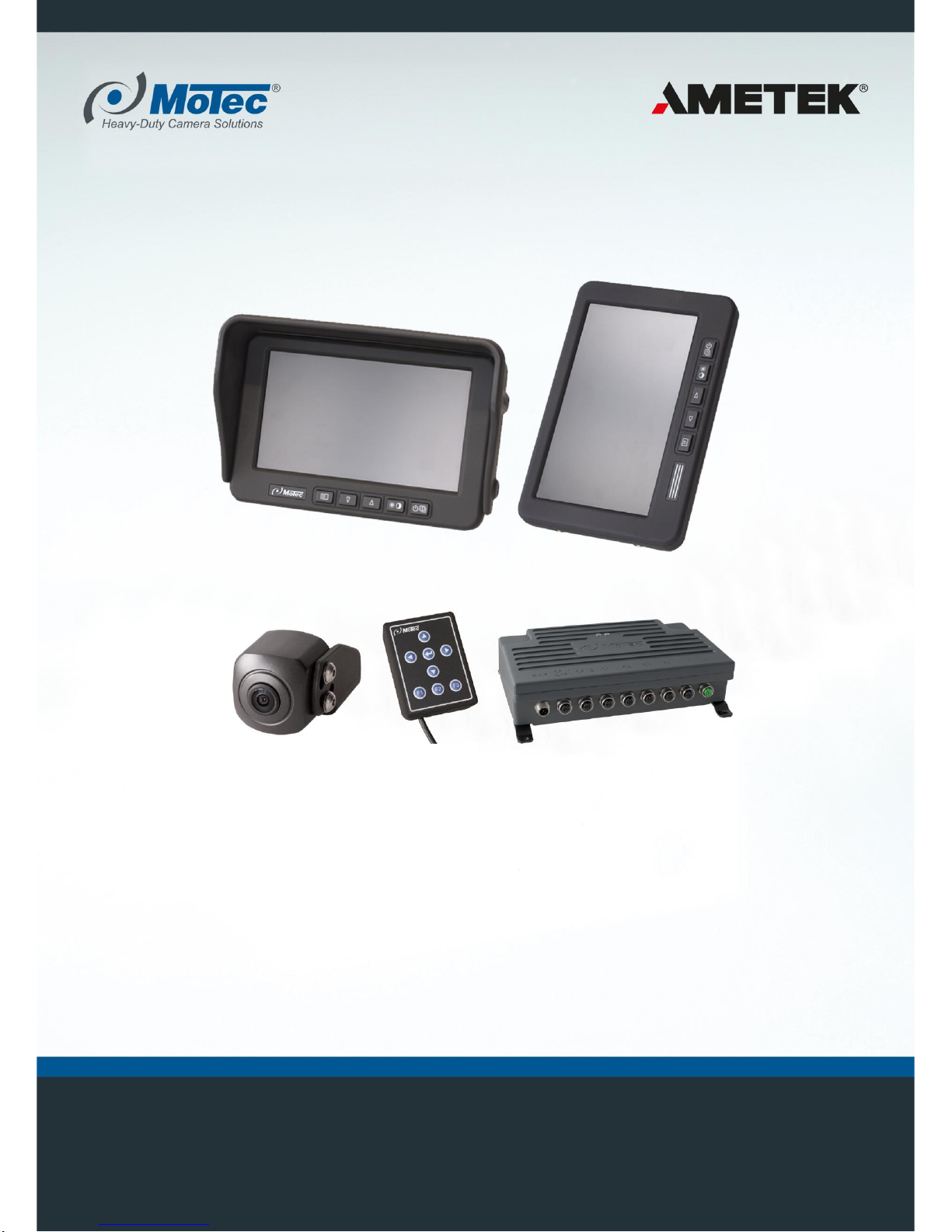
The Mobile Vicinity Scout (MVS) is a camera system
designed especially for utility vehicles. It provides the driver
with a clear, seamless 270° or 360° view around his
vehicle.
The MVS system is used for heavy-duty and commercial
vehicles, which are utilised in the construction industry,
municipal transport and goods traffic, agricultural industry
and logistics.
Fig. 1: Top view (example)
Camera system
The system generates one image of one vehicle side,
using 3 cameras (270° system) or 4 cameras (360°
system). These individual images are processed to
generate a top view. The top view provides a seamless
panoramic view around the area close to the vehicle. This
view increases the safety during manoeuvring.
• During calibration, the system crops the displayed
image to the area near the vehicle.
• Objects in the detection area of the cameras and within
the calibration range are displayed.
• Inserting a customer-specific vehicle image to ensure a
display that is accurate to the contour of the vehicle.
• Display of individual static overlays for the
representation of danger areas, swivel ranges or
support points.
• The open interfaces allow a comprehensive integration
into the vehicle's electronic system and interconnection
with currently installed systems.
Additional camera in the 270° system
An additional camera (e.g., a rear-view camera) can be
connected to the 270° system. The camera image can be
selected via the control inputs or the CAN bus.
Additional sensors
As an option, up to 12 ultrasonic sensors can be connected
to the system in conjunction with the optional MVCU1300-1
control unit.
Objects detected by the ultrasonic sensors are displayed
as coloured dynamic overlays in the top view.
A (pre) warning of objects outside the field of view of the
cameras is possible via the ultrasonic sensors if the
detection range of the ultrasonic sensors is greater than
the calibration range of the cameras shown.

13
3.1 Package contents
1. Verify that all listed components are available for your
system according to the following tables.
2. Based on the information provided on the type plates of
the components, ensure that the type of the
components matches the applicable operating
instructions.
3. Check whether the corresponding operating
instructions or data sheets are available for all
components.
4. Verify all components before use and check for obvious
defects.
5. Report any damage or other defects immediately to
your supplier/service partner.
3.1.1 MVS system
MVS scope of delivery
Component
360°
270°
Video control unit
MVCD1000-x / MVCD1001-x
1x
1x
Wide angle camera
MC7180N
4x
3x
Heavy-duty monitor
MD3071A-V
1x1)
1x1)
Heavy-duty monitor
MD3071A
—
1x
MK723 connection cable
Power supply
1x
1x
MK772 connection cable
Control lead (for MVCD1000-x)
1x
1x
MK798 connection cable
CAN cable (for MVCD1001-x)
1x
1x
MK722 connection cable
Monitor
1x
1x
Connection cable MKS
Camera
4x
3x
1) optional, either MD3071A-V or MD3071A.
PLEASE NOTE
The connection cables are available in different lengths.
The applicable length must be specified when ordering
the system.
3.1.2 Service kit
Delivery scope of Service kit
Component
Quantity
Operator control unit
MBE1000
1x
Ethernet cable
MK773
1x
Calibration targets 1.5 x
1.5 m
PF400, set includes
8 calibration targets
1x
Y-cable CAN-Bus
Only for configuration of the
system if optional ultrasonic
sensors are connected
1x (optional)
PLEASE NOTE
The service kit is only required for the initial start-up and
configuring the MVS system.
The service kit can be used to configure multiple MVS
systems.

14
3.2 Type signs
Fig. 2: System components type sign (example)
1 Match code
2 Article number
3 Serial number
4 Power supply
5 Power consumption
6 Manufacturer’s
address
7 CE mark
8 FCC approval
9 ECE test mark with
approval number
The type signs on the system components correspond to
the example shown above. All information and symbols are
not always available.
Fig. 3: Cable ifentification (example)
1 Match code
2 Article number
3 Batch identification (week of production/year)
A shrink tube is used to attach the cable identification to
ensure, it cannot be lost.
3.3 Technical Data
PLEASE NOTE
For detailed information on the technical data of the
components, please refer to the relevant data sheets.
To download the data sheets of the components go to
http://www.motec-cameras.com/.
3.4 Components
3.4.1 Video control unit
Fig. 4: MVCD1000-x / MVCD1001-x
The video control unit processes the images delivered by
the cameras to a 360° or 270° panoramic view.
The video control unit is available in two versions
depending on the vehicle connection:
MVCD1000-x
Digital control signals are used to connect to the vehicle.
MVCD1001-x
A CAN bus is used to connect to the vehicle.
3.4.2 Camera
Fig. 5: MC7180N
The MC7180N wide angle camera is used for the
270°/360° bird’s eye view system.
The 180° view angle and the small design enable
adaptation to very different vehicle and visibility situations.
•
270° systems use three cameras.
•
360° systems use four cameras.
The cameras are connected to the video control unit via the
MKS cable and are supplied with voltage by the video
control unit.
15
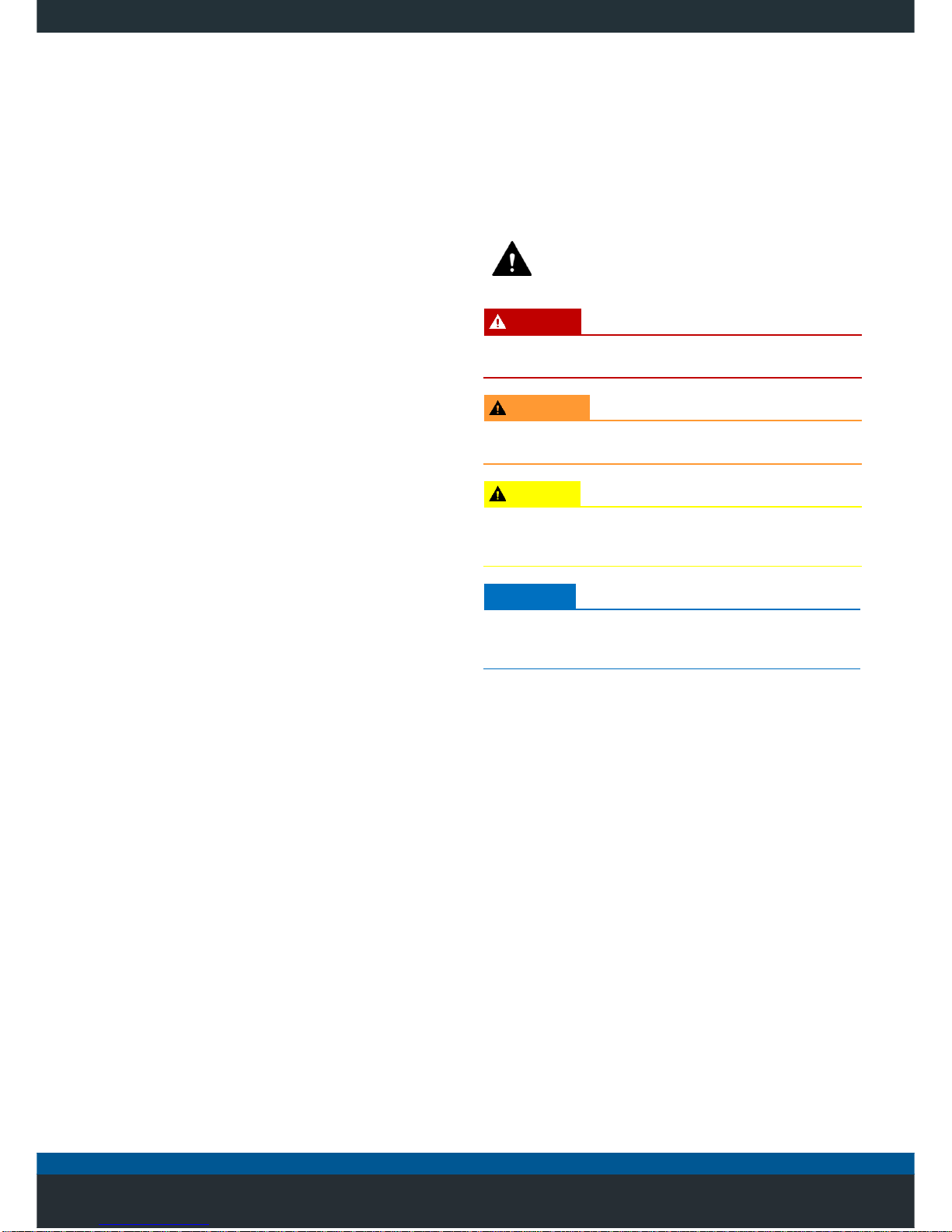
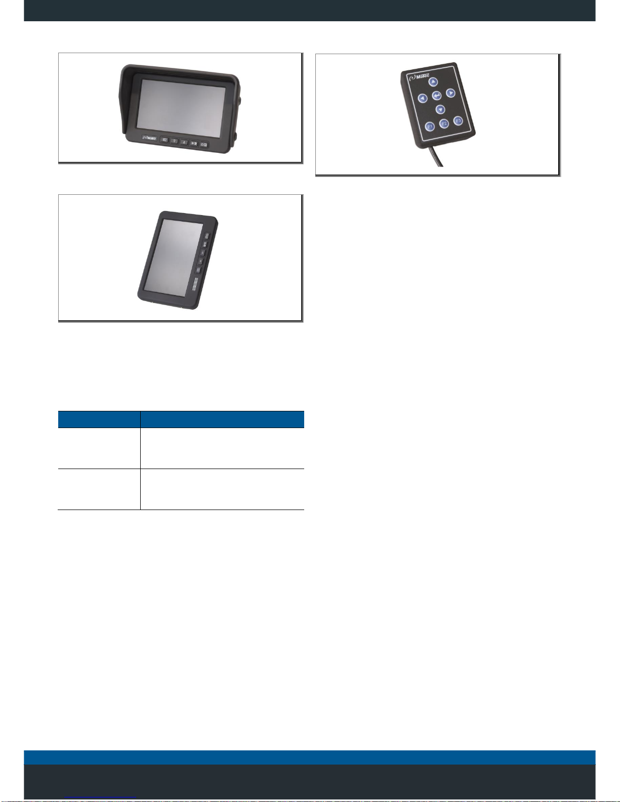
3.4.3 Monitor
Fig. 6: MD3071A
Fig. 7: MD3071A-V
The 7'' monitor displays the image calculated by the video
control unit.
Depending on the system configuration, the monitor is
available in two models:
System
Monitor
360° or 270°
system
MD3071A-V
Vertical monitor alignment (portrait
format)
270° system
MD3071A
Horizontal monitor alignment
(landscape format)
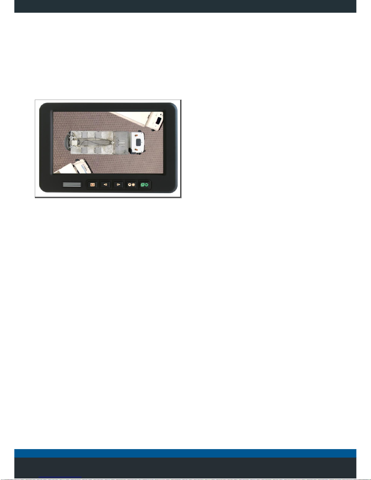
3.4.4 Operator control unit
Fig. 8: MBE1000 operator control unit
The MBE1000 operator control unit is only required for the
initial start-up and configuring the MVS system.
The operator control unit is connected to the CAN 2 port of
the video control unit.
16
4 Installation
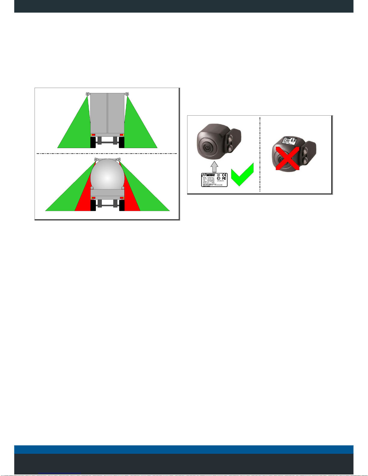
4.1 Selecting the best possible installation
location
Due to the large number of possible vehicle dimensions
and designs, observation of the general notes on the
optimal positioning is highly recommended.
Fig. 9: Camera positions and blind spots
• Keep in mind that convex panels or added
structures may restrict the view.
• In this case, the area immediately next to the
vehicle will not be captured completely, see red
zones Fig. 9.
• Within the context of legal and technical options, it
is possible to use brackets in order to mount the
cameras in order to enlarge the viewing field.
Also observe the following instructions for selecting the
mounting position:
• Position the cameras as high as possible and in the
centre of the relevant side of the vehicle after the
calibration.
• In the case of vehicles which are subject to
authorisation for the transport on public roads,
when the camera protrudes beyond the outer
contour of the vehicle: Mount the cameras at a
minimum height of 2 meters
• When installing the cameras, ensure the type plate
points downwards of the vehicle.
Fig. 10: Type plate position
• Cameras that project the vehicle's contour must be
protected with suitable safety bar or cover.
• Align the cameras in order to ensure that the image
of the vehicle boundaries is captured. The area
around the vehicle must be recorded properly and
the field of view must overlap at least 3 metres.
• Avoid installation positions where add-on
components restrict the view of the road.
• Avoid installation positions subject to excessive
vibrations.
• Never install the cameras on movable attachments.
• Avoid installation positions subject to an increased
risk of contamination.

17
4.2 Installation of the MVCD control unit
• Select an installation location that is not subject to
excessive vibrations.
• Do not install the unit next to a heat source.
• If installed externally, avoid areas subject to an
increased risk of contamination.
• Ensure all plug connectors are easily accessible.
• Use the standard safety socket covers, included as a
standard, and plug them into outlets that are not being
used.
4.3 Installation of monitor
• Always install the monitor outside of the effective area
of the air bags and head impact zone; otherwise there
is a risk of severe injuries.
• Avoid installation positions that restrict the direct view.
• If possible, select an installation position that allows the
driver a direct view from the front and at the same time
provides unobstructed access to all controls.
• Ensure the mounting area is vibration-free.
• If making vehicle-specific brackets, ensure the stability
of the support and the mount is adequate.
4.4 Laying cables
CAREFUL
Damage to the vehicle’s body!
Improper and unsuitable drilling holes can damage the
bodywork and cables.
• Only drill in places without cable runs.
• ensure to protect drill holes with corrosion protection.
CAREFUL
Damage to cables!
Cables can be damaged by mechanical devices or
chemicals.
• Never paint the cable or bring in contact with solvents
of any kind.
• Never install cables near a heat source.
• Compliance with installation instructions is
mandatory.
Since the installation of the cables depends on the
respective vehicle, only general information on cable
routing can be provided.
If in doubt, consult with the vehicle manufacturer to
determine the best possible route.
4.4.1 Preparing for laying
In order to install the cables, you must drill cable glands at
this step and install cable ducts or cable conduits to protect
the cables.
1. Pilot-drill each cable feed-through and then drill the
hole to the required diameter.
2. Deburr all cable feed-through.
3. Drill holes for cable ducts.
4. Install cable ducts or cable conduits.
4.4.2 Laying cables
1. Use cable ties to secure cables and to minimize
mechanical stress
2. If the cables are too long install the cables in loops,
taking into account the minimum installation radii.
 Loading...