

Page 1

MoTeC USA GPS
Part # M GPS BL
Available in 10 Hz or 20 Hz.
USER MANUAL Version 1.4
Page 2

MoTeC USA GPS
Copyright – Motec Systems USA – 2008
The information in this document is subject to change without notice.
While every effort is taken to ensure correctness, no responsibility will be taken for the consequences
of any inaccuracies or omissions in this manual.
15 August, 2008
Page 3

MoTeC USA GPS 2
Contents
Introduction.........................................................3
Warm Up Time ............................................................................ 3
Status LEDs ................................................................................ 4
20 Hz Update Option................................................................... 4
RS-232 Serial Output .................................................................. 4
Speed Output Pulse .................................................................... 5
Speed Ready Output................................................................... 5
Variable Voltage Option .............................................................. 5
Installation...........................................................6
GPS Receiver ............................................................................. 6
Antenna....................................................................................... 6
Loss of Signal.............................................................................. 7
Connection .................................................................................. 7
Connection to ADL2 / SDL / ACL ................................................ 8
Connection to M400 / M600 / M800 ............................................ 9
Connection to ADL ...................................................................... 9
“i2” Analysis Math............................................10
Appendix ...........................................................12
GPS Engine Specifications ....................................................... 12
Power Supply ............................................................................ 12
Operating Temperature............................................................. 12
Physical..................................................................................... 13
Connection ................................................................................13
Page 4
MoTeC USA GPS 3
Introduction
Thank you for purchasing a MoTeC USA GPS receiver. This user’s
guide was written to help you understand how the MoTeC USA GPS
(Global Positioning System) device works. Please read it thoroughly.
Installation is very important, and understanding how GPS works will
help you get the most from this sensor.
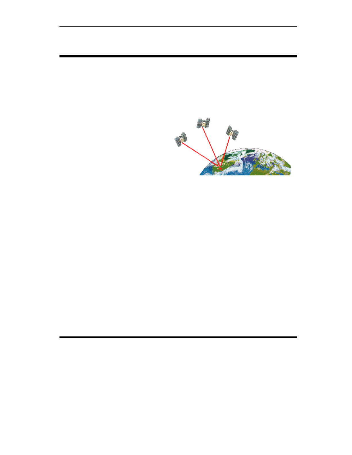
The GPS device uses an
antenna on top of the vehicle to
track satellites in orbit around
earth. It takes a minimum of
three satellites to identify your
position on earth, and a fourth to
calculate accurate timing.
Satellites are constantly moving, and a satellite which the antenna sees
at the start of the race might not be visible 60 minutes later. Satellites
used in the GPS solution are dynamically added or dropped based on
signal quality. Ideally you should have 8 or more satellites being
tracked in order to get good results. Anything under 6 satellites is poor.
With more satellites, there is more information to correctly identify your
position with less error. So it’s easy to see the importance of your
antenna having a clear line of sight to the satellites in the sky.
The system is a 12 channel receiver, but two of the tracked
satellites are special geostationary SBAS which provide DGPS
(differential GPS) via WAAS correction. Therefore the maximum
reported satellites in the data will be 10. Differential GPS uses those
additional satellites to more accurately calculate your position.
Positional accuracy goes from 3 meters to under 1 meter with
Differential GPS.
Warm Up Time
When the GPS receiver is first powered, it will start searching for
satellites to lock onto. This process takes time. It will take longer the
first time you power up at a new location from where you had previously
turned it off. Normal “cold” start up times, meaning being in a new area
from the previous location, can be anywhere from 2 to 10 minutes.
Subsequent “warm” start up times at the same location normally takes
30 seconds to 2 minutes. If you are outside of North American, expect
the very first time to take up to 30 minutes.
Page 5

MoTeC USA GPS 4
Status LEDs
There are 4 LEDs on the front face of the unit
labeled as follows:
• POWER (red): Unit has power.
• GPS (yellow): GPS signals have been
acquired and calculated data is being
sent out.
• DIFF (yellow): SBAS differential satellite available.
• DGPS (green): Differential corrections are active, resulting in
improved data. This is the light you really want to see on.
There are only two required lights for operation, one is POWER and the
other GPS. The DIFF and DGPS lights indicate increased accuracy of
the data. With differential correction, you will get the most accurate
data. Therefore best operation is achieved with these lights on.
20 Hz Update Option
This option allows the following four channels to update at a true
20 Hz rate:
• GPS Latitude
• GPS Longitude
• GPS Speed
• GPS Heading
It’s best to buy this option at the time of purchase. If you buy it
afterwards, the unit must be sent to MoTeC for updating.
RS-232 Serial Output
Standard NMEA-0183 message strings GPGGA and GPRMC are
sent out by default at a baud rate of 57,600. The baud rate and type of
messages can be changed by sending the unit back to MoTeC.
Page 6

MoTeC USA GPS 5
Speed Output Pulse
This output is for devices that can’t accept a RS-232 serial input.
It provides a 0-5 volt square wave output which can be fed into a digital
input on any MoTeC product. The frequency output calibration in
different speed units is:
94 Hz per 1 m/s
940 Hz per 36 km/h
1933 Hz per 46 mph
1.0638 cm per pulse
Speed Ready Output
The speed ready output pin is pulled high to 5v when the speed
signal is good, and low to 0v when there is not enough data for accurate
speed information. The speed output pulse incorporates this speed
ready signal to prevent the speed output from floating around to
erroneous values when the vehicle is stopped.
Variable Voltage Option
You can choose at the time of order to replace the speed output
pulse with a variable voltage output. The speed range should be
specified when ordering.
Page 7

MoTeC USA Installation 6
Installation
GPS Receiver
The enclosure is made from 6061 Aluminum alloy. It should be
mounted in a safe location, away from electrical noise and vibration.
We recommend hook & loop or double sided foam tape. Maximum
operating temperature is 70°C or 158°F.
Antenna
The location of the antenna is VERY important. It should be
mounted such that it can have a clear view of the sky out to 5 degrees
above the horizon. Poor mounting locations will have a large negative
impact on the calculated data.
Normally the best location would be on top of the race car. For
motorcycles, the top rear fairing works well. On a closed-wheel race
car the best choice is the roof. For best performance, do not place the
antenna under the front or rear window. For open-wheeled cars, on top
of the roll hoop, or just in front of the cockpit works best.
The antenna has a magnet base to hold itself onto a metal
surface. Any extra antenna wire can be zip tied in a back and forth
bundle. Do not form a coil with the extra wire or wrap it around
anything.
• GPS signals are easily blocked by electrical noise. Keep the
antenna 12” away from any electrical device. It should also be
more than 6” from any other antennas such as car-to-pit voice
radios, telemetry and other GPS antennas.
• Keep the antenna outside any of any metal or carbon fiber
enclosed space, as these materials will block satellite signals.
Plastic, duct tape as well as fabric convertible tops are
generally ok.
• The antenna should be kept flat or parallel to the ground. If
mounted on a slope then the ability to receive signals will
decrease. Keep this in mind when mounting on a motorcycle
as the bike leans from corner to corner.
Page 8

MoTeC USA Installation 7
• Try to keep the antenna mounted on the centerline of the
vehicle. As with normal wheel speeds, during cornering the
speed of the inner side of the chassis is less than the speed of
the outer side of the chassis.
• If you use double sided tape or hook & loop, when removing
please be careful not to remove the bottom sticker from the
antenna. This sticker has a metal film that help reject false
signals and shield it from noise.
Loss of Signal
As mentioned earlier, the antenna must see as many satellites as
possible. The antenna should have a clear view of the sky, ideally a
clear line of sight to the sky down to 5 degrees above the horizon. If
part of the sky is blocked by a building, tree or bridge then the GPS unit
will loose track of those satellites being blocked. When this happens, a
reacquisition will take place which can take some length of time. Loss
of signal can occur when driving under bridges. The size of the bridge
and satellite location (time of day) has an impact on the acquisition of
satellites. You should always log your satellite count to be aware of
what the antenna saw while traveling around the race track.
Connection
The mating connector is a yellow band AS 610-35SA.
Some early units have the red band AS 610-35SN.
• pin 1 – 12 volt supply, 6 to 18 volts allowed
• pin 2 – Ground,
•
pin 3 – Speed Ground,
• pin 4 – Speed Pulse, connects to digital input
• pin 5 – Speed Ready Signal
• pin 6 – N/C
• pin 7 – N/C
• pin 8 – N/C
•
pin 9 – Serial Ground,
• pin 10 – N/C
• pin 11 – RS-232 Tx, serial data out
• pin 12 – N/C
• pin 13 – RS-232 Rx, usually not required
not 0v but ground or battery negative
optional, internally connected to Ground
optional, internally connected to Ground
Page 9

MoTeC USA Installation 8
Setup for ADL2 / SDL / ACL
For ADL2, SDL or ACL use, please select the template “GPS Standard RMC GGA” listed under the communications RS-232. Verify
57,600 for the baud rate. You’ll be able to log the following channels of
information:
Recommended Logging Rates
Update Option: 10 Hz 20 Hz
• GPS Latitude 20 Hz 50 Hz
• GPS Longitude 20 Hz 50 Hz
• GPS Speed 20 Hz 50 Hz
• GPS Heading 20 Hz 50 Hz
• GPS Date 1 Hz 1 Hz
• GPS Time 10 Hz 10 Hz
• GPS Sats Used 10 Hz 10 Hz
• GPS Altitude 10 Hz 10 Hz
For the 10 Hz update rate, channels should be logged at 20 Hz even
though they only update at 10 Hz. This will help minimize the time delay
between when the data arrives to the logging device through the serial
stream and the moment the values are logged. For the 20 Hz option,
those channels which update at 20 Hz should be logged at 50 Hz. GPS
Date should only be logged at 1 Hz. See the table above.
You can optionally hook up the speed output pulse to a digital
input or speed input set to hall effect with a custom calibration. The
speed output pulse should be logged at 50 Hz. Use a general purpose
channel with 1 dps and rename it to “Speed Pulse”. The calibration
table will contain 2 rows as follows:
0 Hz = 0.0 mph
1933 Hz = 46.0 mph
Page 10

MoTeC USA Installation 9
Setup for M400 / M600 / M800
Wire the speed output pulse into a digital input on the ECU. For the
calibration number, use one of the following:
9400 for km/h
15128 for mph
The maximum speed which can be measured on the ECU through the
digital input is 675 km/h or 420 mph.
Setup for ADL
The ADL does not offer full 32bit logging of GPS positional data. This
limitation prevents the ability to do positional track mapping. Under the
communications setup, select the template “GPS for ADL - RMC
GGA”. You’ll be able to log the following channels of information:
Recommended Logging Rates
Update Option: 10 Hz 20 Hz
• GPS Speed 10 Hz 20 Hz
• GPS Heading 10 Hz 20 Hz
• GPS Altitude 10 Hz 10 Hz
• GPS Sats Used 10 Hz 10 Hz
• Fix Status (Obsolete) 10 Hz 10 Hz
• Year, Month, Day 1 Hz 1 Hz
• Minutes, Sec 10 Hz 10 Hz
• Hundredths of Sec 10 Hz 10 Hz
Channels should be logged at their default rate or the rate at which they
update.
You can optionally hook up the speed output pulse to a digital
input or speed input set to hall effect with a custom calibration. The
speed output pulse should be logged at 50 Hz. Use a general purpose
channel with 1 dps and rename it to “Speed Pulse”. The calibration
table will contain 2 rows as follows:
0 Hz = 0 mph
1933 Hz = 46 mph
Page 11

MoTeC USA Analysis 10
“i2” Analysis Math
GPS data will have an inherent time lag. The sequence of delays
are from receiving real-time satellite signals, processing them, sending
the data into the logger and the logger logging them. MoTeC’s “i2” has
a built-in “Corrected GPS” function found under the “Tools” pull down
menu. This function should only be used with data originating from a
ADL2, SDL or ACL.
Actual shift may vary. You can use either the Auto function, or
manually adjust the time delay. The 10 Hz unit typically has a delay of
approximately 130 msec. The 20 Hz unit typically has a delay of
approximately 110 msec.
Page 12

MoTeC USA Analysis 11
The speed output pulse or variable voltage output should not be
included in the “Corrected GPS” calculations. It will require a separate
time shift function. In “i2” add the following math expression for your
speed pulse channel:
For the Motec ADL, the built in “Corrected GPS” function can not
be used. All channels streaming through the RS-232 interface should
have separate math expressions similar to the above, with a -0.13
second time shift. For the 20 Hz, -0.11 should be used on those
channels. The speed output pulse and speed ready output will have a
time shift of -0.25 seconds.
Page 13

MoTeC USA Appendix 12
Appendix
GPS Engine Specifications
12-channel GPS engine.
Horizontal accuracy < 1 meter at 95%
Update rate of 10 Hz or 20 Hz optional.
Screw on SMA antenna connector.
57600 kbit/s baud rate, other rates available upon request.
NMEA standard $GPGGA and $GPRMC data, other messages
available upon request.
Digital output pulse: 0-5v with 50% duty cycle
94 Hz per 1 m/s
940 Hz per 36 km/h
1933 Hz per 46 mph
1.0638 cm per pulse
(can be connected to inputs which have a 12v pull up
resistor but output will still be 0-5v square wave)
Power Supply
Operating Voltage: 6 to 18 Volts DC
Operating Current: 0.380 Amps at 12 Volts
Operating Temperature
Ambient Temperature Range: -22°F to 158°F / -30°C to 70°C
Housing Material: Anodized 6061 Aluminum
Page 14

MoTeC USA Appendix 13
Physical
Case Size: 3.95” x 2.7” x 0.9” (excluding connectors)
100 mm x 69 mm x 23 mm (excluding connectors)
Weight: 164 grams without antenna
Connection
The mating connector is a yellow band AS 610-35SA.
(Some early units have the red band AS 610-35SN)
• pin 1 – 12 volt supply, 6 to 18 volts allowed
• pin 2 – Ground, not 0v but ground or negative battery
• pin 3 – Speed Ground, optional, internally connected to Ground
• pin 4 – Speed Pulse, connects to digital input
• pin 5 – Speed Ready Signal
• pin 6 – N/C
• pin 7 – N/C
• pin 8 – N/C
• pin 9 – Serial Ground, optional, internally connected to Ground
• pin 10 – N/C
• pin 11 – RS-232 Tx, serial data out,
For ADL or ADL2 connect to pin 79
For SDL connect to pin 34
For ACL connect to pin 15 or pin 20
• pin 12 – N/C
• pin 13 – RS-232 Rx, usually not required
Page 15

MoTeC Notes 14
 Loading...