

Page 1
MoTeC SKM and OKM User Manual
Contents
Introduction ................................................................................ 2
Getting Started ........................................................................... 4
Installation .................................................................................. 5
SKM ......................................................................................................... 5
OKM ......................................................................................................... 5
Configuration ............................................................................. 6
Knock Detection....................................................................................... 6
Knock Module Configuration ................................................................... 8
Operation .................................................................................. 23
Appendices .............................................................................. 24
Appendix 1 SKM Internal Dip Switch Settings ....................................... 24
Appendix 2 SKM Connector, Pin Out and Wiring .................................. 26
Appendix 3 SKM Tuning Loom #61114 ................................................. 27
Appendix 4 Gold Wave Settings ............................................................ 29
Appendix 5 Detonation Explained ......................................................... 31
ESD - Antistatic
All necessary antistatic precautions must be taken while handling circuit
boards.
Copyright© 2008 – MoTeC Pty Ltd
The information in this document is subject to change without notice.
While every effort is taken to ensure correctness, no responsibility will be taken for the
consequences of any inaccuracies or omissions in this manual.
Version 1.0, 24 October 2008
Page 2

2 Introduction
Introduction
MoTeC’s Knock Modules provide individual cylinder closed loop knock
control, allowing tuners to safely optimise high performance ignition maps.
There is a standalone module compatible with all 'hundred series' ECUs and a
version specifically designed to mount onto an M800 Plug-In ECU. Both
modules work in conjunction with MoTeC’s ECU Manager software (v3.5 and
up)
Standalone Knock Module (SKM)
This module is housed in a robust aluminium casing that can be mounted as
required in any vehicle. It is wired between the ECU and the knock sensor.
Onboard Knock Module (OKM)
This module is fitted onto the board of an M800 Plug-In ECU prior to delivery
and linked to the knock sensor. M800 Plug-In ECUs are available for selected
vehicles. Please check our website at www.motec.com.au
for details.
Basic Specifications
SKM OKM
Inputs
Outputs
Physical
y Knock sensor input
y Knock window input
y Power supply 8 V
y Knock sensor out
y Audio
y Case size 38 x 90 x 25 mm
excluding connector
y Weight 100 grams
y 1 x 13 pin Autosport
connector
y Audio
y Fitted onto a M800 Plug-In
ECU
Page 3

MoTeC Introduction 3
Other information
Compatibility
Related
software
Accessories
SKM OKM
y ‘hundred series’ ECUs;
M400, M600, M800 and
M880
y All knock sensors
y ECU Manager software
v3.5 and up
(software version 2.3
enables monitor only)
y i2 Data Analysis
y Gold Wave Audio
Analysis Software (for
frequency analysis only)
y Stereo headphones
y Knock sensor
y SKM tuning loom #61114
(optional)
y M800 Plug-In ECUs
y ECU Manager software
v3.5 and up
(software version 2.3
enables monitor only)
y i2 Data Analysis
y Gold Wave Audio
Analysis Software (for
frequency analysis only)
y Stereo headphones
Page 4

4 Getting Started
Getting Started
The Knock Modules have no stand-alone Manager software.
All knock control configuration is done through MoTeC's ECU Manager
software (version 3.5 or up). This can be downloaded from the MoTeC
website at www.motec.com
can be found in the ECU User Manual
For frequency analysis MoTeC recommends Gold Wave Audio Analysis
Software. A trial version can be downloaded from www.goldwave.com
PC requirements
• Operating System: Windows XP and up
• Audio and USB input
• Sound card capable of simultaneously recording and playing.
Alternatively, an external soundcard or third party device can be used.
. Further information on ECU Manager software
Page 5
MoTeC Installation 5
Installation
SKM
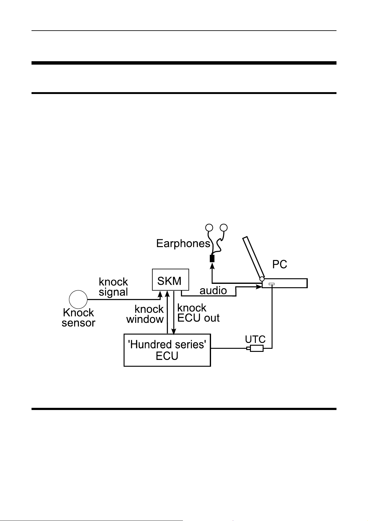
The SKM is connected between the OEM fitted knock sensor and a 'hundred
series' ECU – M400, M600, M800 or M880.
The SKM knock signal output must be connected to the ECU via an available
analogue voltage input, preferable a Lambda sense input. The Lambda sense
input has a slightly higher resolution.
To send the gated window signal to the knock module connect a spare
injector or ignition output on the M800 or M880 ECU to the SKM input. On the
M400 and M600, injector 8 output must be used.
Alternatively the SKM Tuning loom can be used (available separately)
See appendix 2 and 3 for detailed wiring instructions
OKM
The OKM is fitted directly onto the board of an M800 Plug-In ECU.
Most M800 Plug-In ECUs fitted with an OKM are pre-configured to analogue
voltage input AV5 and ignition output 6. WRX9/10 boards use lambda 1 sense
input rather than AV5.
Page 6
6 Configuration
Configuration
When suffering detonation, each engine/chassis combination and associated
accessory package resonates at different frequencies. To configure an
electronic knock control system, the exact combination of engine, engine
mount, exhaust system, alternator and starter etc. must have been fitted.
A reliable electronic knock control system requires detecting knock accurately
and differentiating knock from normal engine noise.
MoTeC’s knock modules use the vehicle’s original, factory-fitted knock
sensors to detect detonation, improving this detection by reducing the
influence of background engine noise using a combination of data gating and
frequency filtering.
The engine sound energy during engine operation will vary for different
frequencies in the spectrum. The knock sound energy will be more prominent
at certain frequencies.
A competent tuner needs to carry out a frequency analysis to determine the
frequency where the difference of the engine sound with and without
detonation is most clear to detect. The centre frequency settings of the Knock
Module must match this frequency.
The Knock Control system in the ECU can then be configured to adjust the
ignition according to measured knock levels.
Knock Detection
Knock Sensor
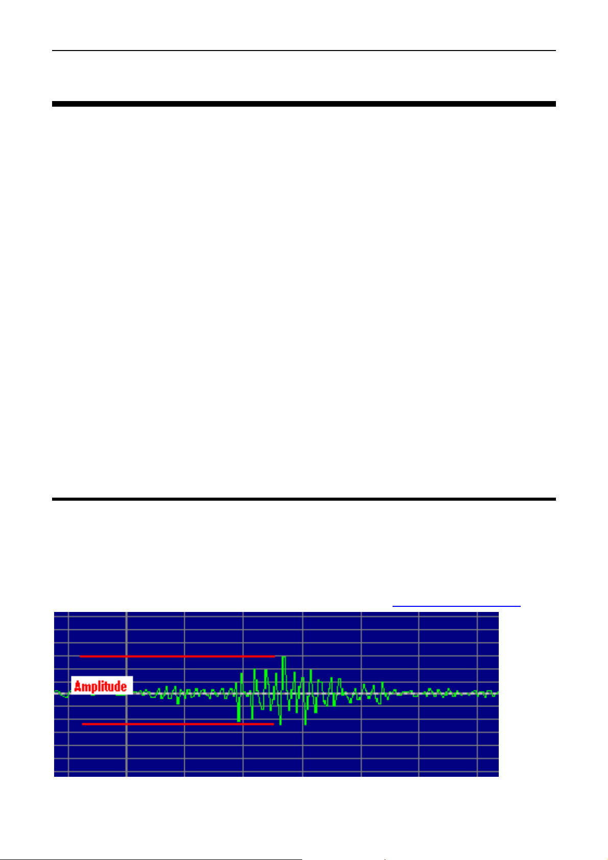
The knock sensor measures the engine vibrations and turns this into an AC
waveform output.
The next figure shows a zoomed in view of typical knock sensor signal
(captured using Gold Wave Audio Analysis Software www.goldwave.com
).
Audio signal output from a knock sensor
Page 7
MoTeC Configuration 7
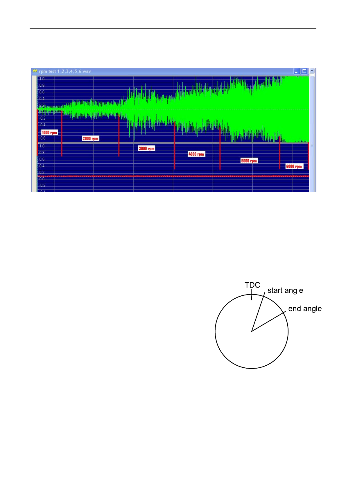
With increasing engine RPM, the higher engine vibrations will result in an
increase in the amplitude of the knock sensor signal. A race engine operating
at high RPM will show high amplitudes making it difficult to detect knock.
Knock sensor signal with increased engine RPM
Knock Modules
The SKM/OKM modules improve knock detection by reducing the influence of
background engine noise using a combination of data gating and frequency
filtering.
Data Gating
The knock window is the period in the
combustion cycle during which knock is likely
to occur, normally between 10 and 50 degrees
after TDC (top dead centre). The ECU sends a
knock window signal to the Knock Module to
mark the start and end angle in the engine
cycle.
The SKM/OKM will measure the knock sensor
signal during this window and sends the
information to the ECU. The ECU uses the
measurement to calculate the knock
percentage for each cylinder of the engine.
Knock window
Frequency Filtering
To correctly identify knock, the SKM switches must be set to match the
theoretical best centre frequency. The centre frequency in the SKM/OKM is
normally set to the frequency of the engine that shows the greatest energy
difference between normal engine operation and active detonation.
Page 8
8 Configuration
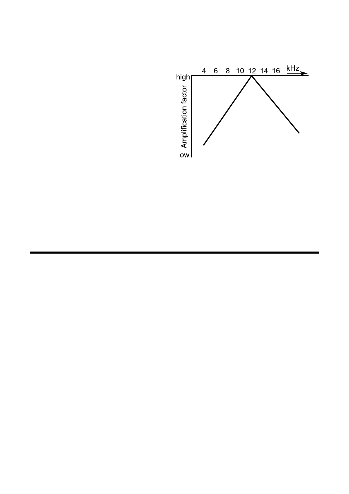
The knock module filters and amplifies the signal transmitted from the knock
sensor based on the centre frequency. Signals of the selected centre
frequency pass the frequency filter
amplified, while signals in other
frequencies will be reduced. The
further away from the centre
frequency, the more the signal will
be reduced. Filtering will reduce the
influence of background engine
noise resulting in improved knock
detection.
The figure shows frequency based
amplification with the centre
frequency set to 12 kHz.
Frequency based amplification
Gain Factor
A gain factor is only required for knock sensors with very low output levels.
The gain factor can be chosen to multiply the raw knock output signal, prior to
frequency filtering. It is also possible to set a gain factor from ECU Manager
software.
Knock Module Configuration
The configuration of the Knock Modules consists of two stages:
Stage 1: Carrying out a frequency analysis of the knock sensor signal to
determine the centre frequency and knock module settings. This needs to be
done by a competent tuner, as incorrect operation can easily result in severe
engine damage
Stage 2: Tuning the knock control system
Note: The OKM settings are preconfigured to suit the standard vehicle. It only
requires the second configuration stage to tune the knock system. If the
vehicle is modified significantly, contact an authorised MoTeC dealer for
further advice.
Before carrying out any stage of the configuration the vehicle needs to be
prepared by setting up the ECU for knock measuring and data logging using
ECU Manager software.
Page 9

MoTeC Configuration 9
Preparation
Configuring the Knock Window
y On the Adjust menu select injector/ignition output functions
y Select injector/ignition out [#]
Select injector or ignition output the SKM//OKM is wired to.
Note: For M400/M600 Inj8 must be used.
y Select Function
y Type Function value 122 (Knock Window)
y Press ESC
y Select Parameters
Start Ref
0: knock window measured after ignition point
1: knock window measured after TDC
Typical value 1
Start Angle
The starting angle of the knock window in the engine cycle where the
knock sensor signal is recorded
Unit: degrees
Typical value 10
Slow End Angle
The end angle of the knock window in the engine cycle when
operating at slow engine RPM (up to 1000 RPM)
Unit: degrees
Typical value 40
Fast End Angle
The end angle of the knock window in the engine cycle when
operating at fast engine RPM (RPM as specified in RPM Limit)
Unit: degrees
Typical value 50
Polarity
0: output high for 0% duty
1: output low for 0% duty
Value 0 is required for SKM/OKM
Page 10

10 Configuration
Configuring the channel Knock Voltage
y On the Adjust menu click Sensor Setup
y Click Input Setup…
this will open the Input Pins Setup screen
y Click the Other tab
y Select Knock Voltage (Knock V)
y Click Change
y In the Input Source list click AV[#] or Lambda[#] (Select the
input the SKM//OKM is wired to)
y In the Calibration area select Predefined and in the list click
#31 Volts(V); x1 (5.000V=5.000V)
Knock Gain Table
y On the Adjust menu click Functions
y Click Knock Control
y Click Gain
This table compensates any sensitivity differences of the sensor to
particular cylinders.
The Knock Gain table should be used in conjunction with the Knock
Offset table to level out any differences between the individual
cylinders.
Typical starting value: 1.00
Note: The values in this table must be non-zero to show any Knock
Percentage values.
Data Logging Setup
Each cylinder's knock input should be logged at 50 Hz or greater.
• On the Adjust menu click Data Logging Setup
• Click Knock Levels
• Select Knock Limit and type 10
• Select Knock 1 and type 50 (or greater)
• Continue the last step for all remaining cylinders in firing order
Follow the same procedure to log other useful channels.
Recommended channels are:
y Knock Retard Short Term for each cylinder
y Knock Retard Long Term for each cylinder
y Individual Ignition Advance channels - to evaluate the
performance of the control system during calibration tuning.
Page 11

MoTeC Configuration 11
Frequency Analysis
A competent tuner with the right equipment can measure and analyse the
knock frequency for the specific engine and associated hardware by
comparing the sound of the engine with and without detonation. Frequency
analysis will determine the theoretical best centre frequency. This is the
frequency where the difference of the engine sound with and without
detonation is most clear to detect.
Surprisingly minor changes to the engine hardware will affect the frequency of
the detonation “ring” throughout the structure. So frequency settings that suit
one car may not be suitable for another car of the identical model but with
slight modifications.
Warning
Knock frequency analysis is a specialised job, to be carried out
by experienced technicians. Incorrect operation can easily cause
severe engine damage.
Setup
1. Using the SKM tuning loom, connect an audio lead to the line in or
microphone in port on the PC.
The PC must be able to record sounds through a line in port and
simultaneously play it to the headphone jack, so the operator can
listen and monitor the engine while recording.
Note: If your computer does not have the ability to record and listen
at the same time an alternative method should be used to listen to the
engine e.g. an external sound card or third party device.
2. Configure the PC to play sound only from the left channel. The right
channel is the knock window signal sent from the ECU.
Tip: You can make an adapter plug for the headphones that joins the
sound from the left and right channel.
3. Connect audio headphones to the PC.
Tip: To block out external engine and car noise, bud type ear phones
with high quality ear muffs used over top can be used.
4. To perform frequency analysis on the recorded audio file requires
dedicated software.
In this document Gold Wave software is used in all examples.
See Appendix 4 Gold Wave Settings
Page 12

12 Configuration
Test
1. Ensure the engine is at normal operating temperature.
2. Run the engine and listen for any irregularities in engine vibrations
like internal component noise.
3. If all sounds normal bring the engine under some load and carefully
introduce light detonation.
Tip: To introduce detonation at as light a load as possible, use a low
octane fuel.
4. Proceed with extreme caution and note where detonation can be
introduced. Return to no detonation.
5. Open a new file in Gold Wave and record the data while running the
engine from a normal operating situation to a situation with detonation
at a similar engine speed.
6. Shut down the engine.
Analysis
1. Configure the Gold Wave Software so that the sound recording can
be viewed on a spectrogram (see appendix 4).
2. Play back the Gold Wave audio file.
The Y-axis on the spectrograms chart is the frequency range, the Xaxis is the playback time.
The colours on the chart represent the energy of the recorded sound.
The key to the colours is underneath the X-axis.
3. Look at the spectrogram chart, while listening for detonation. The
colour in the spectrogram changes at the moment detonation occurs.
4. The colour change occurs at the knock frequency, but there are often
reflections of the detonation at other frequencies.
5. Determine the frequency where the difference of the engine sound
with and without detonation is most clear to detect. This will be the
centre frequency setting.
Page 13

MoTeC Configuration 13
Examples
The following examples show how to interpret the data and choose the centre
frequency.
Example 1
In the next spectrogram, increased energy levels show consistently at
8 kHz. The noise at this frequency is constant even when the engine is not
detonating, therefore we can assume that this is normal engine
background noise. Detonation, introduced via an ignition timing adjustment
in the ECU, can be seen at the 3.5 second mark. Here extra energy levels
are seen throughout all frequencies.
To determine which frequency has the best ratio between little background
noise energy and high detonation intensity compare the areas with and
without detonation.
In the example, at 5 kHz there is little background noise and a touch of
yellow (high energy) at the detonation point. The highest detonation
energy is at 8 kHz, however the background noise is also high here.
To help selecting the best centre frequency, experiment with different
settings while downloading the log files from the ECU. Analyse the log files
using i2 data analysis software.
The log files will show the individual cylinder knock channels. They are
represented as a percentage. The absolute value is at this moment not
relevant.
Important is a low background noise level and a high actual knock
signal.
The log file with a setting of 8 kHz might equal background noise levels of
approximately 60% and mild knock shows peaks of 90%.
A log file with a setting of 5 kHz might equal background noise levels of
approx 25% and mild knock showing peaks of 70%.
Therefore a centre frequency setting of 5 kHz would in this example likely
be the best.
Note: The centre frequency will affect the overall level of the knock voltage
channel.
Page 14

14 Configuration
Frequency spectrogram in GoldWave
Page 15

MoTeC Configuration 15
Example 2
The Mitsubishi Evolution Lancer series has a narrowband knock sensor
that transmits a signal different to wideband knock sensors.
The voltage amplitude is high compared to signals from wideband sensors
for the same level of engine noise, so overall energy levels will be high.
The next spectrogram shows a signal from a narrowband knock sensor. It
shows severe detonation at the 2 seconds mark (yellow energy spikes).
The background noise and detonation is concentrated on one frequency,
in this case13 kHz.
Mitsubishi Evolution Lancer: knock frequency analysis
With an example setting of 13 kHz, the log file from the ECU might show
background noise level at 50%- 70% and mild knock showing peaks of
90%. This makes it difficult to detect severe detonation, so an SKM/OKM
centre frequency setting of 13 kHz would be inappropriate.
The detonation energy is high enough to reflect through other frequencies.
For example at 7 kHz, there is less background noise and still relatively
high detonation intensity.
With a setting of 7KHZ the log file from the ECU might show background
noise level at 30-40% and mild knock at 60%. With this setting larger
detonation events can be measured with appropriate action taken as a
result. This would therefore be a better choice for the correct setting.
Page 16

16 Configuration
Log file from ECU with a centre frequency setting of 13 kHz
Log file from ECU with a centre frequency setting of 7 kHz
This example highlights the complexity involved in determining knock and
appropriate centre frequency settings for each application.
Page 17

MoTeC Configuration 17
Example 3
The car from the previous example has been converted to rally
specifications. This involved fitting a roll cage, larger exhaust etc. Other
than a restrictor the engine remains unchanged.
The knock sensor signal is now concentrated on 12 kHz rather than
13 kHz and the characteristics are different.
In this case a centre frequency of 6 kHz may be more appropriate.
Mitsubishi Evolution Lancer r a lly spec: knock frequency analy si s
Centre Frequency Setting
After the knock frequency has been assessed and a centre frequency chosen
the Knock Module must be setup accordingly.
For instructions on changing the SKM switch settings, see appendix 1.
Note: The OKM settings are preconfigured to suit the standard vehicle.
However, should adjustment be required because the vehicle is modified
significantly, contact an authorised MoTeC dealer for further advice.
Page 18

18 Configuration
Tuning Knock Control System
Note: The following tuning is a specialised job, to be carried out
by experienced technicians. Incorrect operation can easily cause
severe engine damage.
The knock control system will retard the ignition timing depending on the level
of knock. There is an instantaneous setting to reduce the knock levels
immediately and a long term retard setting to prevent knock re-occurring.
i2 data showing the instantaneous (short) and long term retard effect on knock levels
Page 19

MoTeC Configuration 19
The knock control settings are adjusted in ECU Manager software.
• On the Adjust menu click Functions
• Click Knock Control
• Click Setup to enter Knock Control and set the following parameters
Activate Throttle Pos
Specifies the throttle position which must be exceeded to activate
knock control
0: Disabled - knock control always active
Unit: Percentage (%)
Activate Full Throttle Time
Knock control will only activate when the full throttle timer exceeds
this value.
0: Off – Ignore full throttle timer
Units: seconds
Maximum RPM
Knock control is disabled once Engine RPM exceeds this value.
Useful when background noise becomes excessive and clear knock
detection is no longer possible.
Normally set to 50 RPM below the RPM limit as engines running on
the RPM limit may knock intermittently.
Mode
0: Individual cylinder knock control
1: Global knock control. All cylinders will be retarded equally.
Usually set to 0.
If set to 1 the control system will retard all cylinders, regardless of the
cylinder on which the knock was measured.
Error Retard
Specifies the amount of permanent retard that will be applied to all
cylinders if the knock sensor goes into error as defined by the
diagnostic levels in the input setup.
Unit: Degrees
Warning Trigger
Specifies the level above the Knock Target Threshold (value from
Knock Table) which, if exceeded will cause a warning to be
generated.
Page 20

20 Configuration
Note: Requires the Driver Warning Alarm function to be configured on
an auxiliary output.
Note: The knock warning is included in Status Group 3.
Unit: Percentage (%)
Retard Gain (Instantaneous Term)
Defines the amount of retard applied for each percent over the Knock
Target Threshold (value from Knock Table).
Unit: Degrees/Percent
e.g.: Retard gain = 0.5 and knock= 20% over the Knock Target
Threshold would result in 10 degrees ignition retard
Advance Rate
Rate at which ignition retard is advanced back to normal.
Unit: Degrees/Second
e.g.: Advance rate = 2 would result in the ignition to advance back at
a rate of 2 degrees per second.
Retard Limit
Maximum amount of retard from the current ignition timing (from
Ignition Table)
Unit: Degrees
e.g.: Retard Limit = 10 and current ignition timing = 25 degrees BTDC
then the Instantaneous term trim aspect of the Knock Control
Function can retard to 15 degrees BTDC.
Retard Rate Long term
Amount of long term retard applied per second for each degree of
instantaneous term trim retard applied.
Unit: Degrees/Second/Degree
e.g.: Retard Rate Long Term = 0.200 and currently active
Instantaneous Term trim = 8 degrees, then 1.6 degrees/second long
term trim is also applied.
Advance Rate Long Term
Long term rate at which ignition is advanced back to normal.
Unit: Degrees/Second
e.g.: Advance Rate Long Term = 0.050 would result in the ignition to
advance back at a rate of 1 degree in 20 seconds.
Retard Limit Long Term
Maximum amount of long term retard the Knock Control function can
remove from the current ignition timing (from Ignition Table)
Page 21

MoTeC Configuration 21
This is added to the value in Retard Limit for the Instantaneous term
trim.
Unit: Degrees
e.g.: Retard Limit = 10, Retard Limit Long Term = 6 and
current ignition timing = 25 degrees BTDC then the Knock Control
Function can retard to 25 – (10+6) = 9 degrees.
• When all parameter settings are completed, click ESC
• Click Knock Table to enter the Knock Table window
This table sets the Knock Target Threshold (or Knock Limit) for the
Knock Control function.
The ignition will not be retarded unless the measured knock value of
any of the cylinders exceeds the Knock Target Threshold value.
To determine Knock Target Threshold values, run the engine in a non
knocking condition with safe ignition timing. Operate the engine fully
loaded through all RPM levels and note the background noise levels
in the cylinders knock percentage channels.
The Knock Table is configured with RPM as X-axis. As a starting
point, values are to be entered at 5 to 10% above background noise
levels.
• When all Knock Table settings are completed, click ESC
• Click Gain to enter the Knock Gain Table
This table compensates any sensitivity difference of the sensor to
particular cylinders.
The Knock Gain table should be used in conjunction with the Knock
Offset table to level out any differences between the individual
cylinders.
Typical starting value: 1.00
Note: The values in this table must be non-zero to show any Knock
Percentage values.
• When all Gain settings are completed, click ESC
• Click Offset to enter the Knock Offset Table
This table compensates for any offset differences of the sensor to
particular cylinders.
The Knock Offset table should be used in conjunction with the Knock
Gain table to level out any differences between the individual
cylinders.
Typical starting value: 0
Page 22

22 Configuration
Knock Tuning Tips
y Set both Retard Limit and Retard Limit Long Term to 0 degrees.
y Listen for detonation while running the engine.
y Introduce light detonation very carefully and log the knock
percentages.
y Estimate the Ignition Retard required preventing this level of knock
continuing.
y Adjust the Instantaneous Term trim parameters:
Start with values which will cause too much retard.
Work your way back until an appropriate strategy for the type of
engine is found.
y To start, work with Instantaneous Term trim only
y Add the Long Term trim parameters later if required.
Page 23

MoTeC Operation 23
Operation
Once the Knock Control System is tuned, it can be used for continuous
monitoring.
The configuration will generally not need any adjustment. Only major changes
in engine (exhaust, cams, pistons etc) and transmission might require a new
centre frequency setting.
In this case, the vehicle should be returned to the dealer for a new frequency
analysis.
Page 24

24 Appendices
Appendices
Appendix 1 SKM Internal Dip Switch Settings
Dip switches are used to set the gain factor, centre frequency and the
differential mode switch.
To access the switches, remove the 4 lid locating screws. Hold the device as
shown in the photo to see the various switch identification codes.
SKM Dip Switches
Switch down toward the circuit board = on
Switch up away from circuit board = off
Page 25

MoTeC Appendices 25
Differential Mode Switch
DM Function
off normal knock sensor connection (default)
on differential sensors
Gain Switches
G2 G1 G0 Gain
On on on 2 (default)
On on off 4
On off on 8
On off off 16
Off on on 16
off on off 32
off off on 64
off off off 128
Knock Centre Frequency Switches
F3 F2 F1 F0 Frequency
off on on on 5 kHz
off on off on 6 kHz
off on off off 7 kHz
off off on on 8 kHz
on off off on 9 kHz
on on on on 10 kHz (default)
on on off on 12 kHz
on on off off 14 kHz
on off on on 16 kHz
Page 26

26 Appendices
Appendix 2 SKM Connector, Pin Out and
Wiring
Connector
Autosport 13 pin
Mating connector #65041
SKM Connect to
Pin Function Device/connector Input
1 Select 0
2 Select 1
any available AV input,
3
Knock ECU
Out
M400/M600/M800/M800
preferable a Lambda
sense input
4
Knock Audio
Out
5 Audio Ground 3.5 mm stereo connector ring (ground)
6 Sensor 1 Input knock sensor signal
7 Sensor 2 Input
8 Sensor 3 Input
9 Sensor 4 Input
10 Shield knock sensor shield
Knock
11
Window
3.5 mm stereo connector tip (left channel)
M400/M600 injector8 only
M800/M880
3.5 mm stereo connector
any spare ignition or
injector output
via 100 KΩ resistor to
ring
(right channel)
12 8 V M400/M600/M800/M880 8 V
13 Ground M400/M600/M800/M880 ground
Page 27

MoTeC Appendices 27
Appendix 3 SKM Tuning Loom #61114
Optionally the SKM Tuning Loom can be used for wiring.
• Length of the ECU and knock sensor leads is 600 mm
• Length of the audio lead is 1850 mm
Connector 1: Stereo plug
Pin Function
Base Audio Ground
Connect to stereo headphones
Middle right channel Knock Window
Tip left channel Knock Audio Out
Connector 2: DTM 2 pin
Mating connector #68051
Pin Function Connect to knock sensor
1 Shield Shield
2 Knock Signal Signal
Connector 3: DTM 4 pin
Mating connector #68054
Pin Function Connect to M400/M600/M800/M880
1 Ground Ground
2
Knock ECU
Out
Knock
3
Window
4 8 V 8 V
Any available AV input, preferable a Lambda sense
input
Any spare ignition or injector output
Note: on M400/M600 injector8 only
Page 28

28 Appendices
Page 29

MoTeC Appendices 29
Appendix 4 Gold Wave Settings
To set up the side display as a Spectrogram for analysing frequency of
sounds:
On the Options menu click Control Properties (keyboard shortcut F11)
In the Left Visual box, select Spectrogram <GoldWave*>
Page 30

30 Appendices
On the Tool menu click Control
Right click in the screen to open the menu and select Spectrogram
<GoldWave*>
Click Properties to configure the spectrogram.
Choose Fixed frequency range and set range to From (Hz) 3000 To (Hz)
18000
Choose Show Axis
Page 31

MoTeC Appendices 31
Appendix 5 Detonation Explained
Detonation (also called "spark knock") is an erratic form of combustion that
can cause catastrophic engine failure. Detonation occurs when excessive
heat and pressure in the combustion chamber causes the air/fuel mixture to
self ignite. This produces a sudden rise in cylinder pressure accompanied by
a sharp metallic pinging or knocking noise. The hammer-like shock waves
created by detonation subject the head gasket, piston, rings, spark plug and
rod bearings to severe overloading. Mild or occasional detonation can occur in
almost any engine and normally causes no harm. But prolonged or heavy
detonation can be very damaging.
Detonation is the result of an amplification of pressure waves, such as sound
waves, occurring during the combustion process when the piston is near top
dead centre (TDC). The actual "knocking" or "ringing" sound of detonation is
due to pressure waves pounding against the insides of the combustion
chamber and the piston top. It is not due to 'colliding flame fronts' or 'flame
fronts hitting the piston or combustion chamber walls.'
Normal Combustion
This is the burning of a fuel and air mixture charge in the combustion
chamber. It should burn in a steady, even fashion across the chamber,
originating at the spark plug and progressing across the chamber in a three
dimensional fashion. Similar to the ripples spreading out when a pebble is
thrown into a pond with a glass smooth surface, the flame front should
progress in an orderly fashion. The burn moves all the way across the
chamber and quenches (i.e.: cools) against the walls and the piston crown.
The burn should be complete with no, or very little, remaining unburnt fuel-air
mixture. Note that the mixture does not "explode" but burns in an orderly
fashion.
During combustion, the location of peak pressure (LPP) can be measured
with an in-cylinder pressure transducer. When the spark is fired at optimum
timing the burn is initiated at the spark plug and will progress evenly through
the chamber to reach peak pressure shortly after top dead centre depending
on the chamber design and the burn rate. Ideally, the LPP should occur
between 12 and 15 degrees after top dead centre.
Page 32

32 Appendices
Combustion chamber at TDC
Abnormal Combustion – Detonation
If conditions for combustion are not ideal, detonation can occur. This usually
happens first at points of amplification of the pressure waves.
For example at the edges of the piston
crown where reflecting pressure waves
from the piston or combustion chamber
walls can constructively recombine – this
causes very high local pressures. If the
speed at which this pressure build-up to
detonation occurs is greater than the
speed at which the mixture burns, the
pressure waves from both the initial
ignition at the spark plug and the
pressure waves coming from the
problem spots can set off immediate
explosions in the remaining air/fuel
mixture, rather than smooth combustion.
The remaining fuel in the end gas simply
lacks sufficient octane rating to withstand
this combination of heat and pressure.
Combustion Pressure with detonation
Page 33

MoTeC Appendices 33
Detonation causes a very large, very rapid, pressure spike of very short
duration in the combustion chamber. The pressure trace of the combustion
chamber process would show the normal burn as a steady pressure rise, and
then all of a sudden a very sharp spike when the detonation occurred. The
pressure spike creates a force on the combustion chamber causing the
structure of the engine to ring or resonate (much as if it were hit by a
hammer). Resonance, which is characteristic of combustion detonation,
occurs between 4 to 12 kHz resulting in the audible pinging. This noise or
vibration is what the knock sensor detects.
Detonation Indicators
The best indication of detonation is the pinging sound that cars, particularly
old models (pre 1980) make at low speeds and under load. It is very difficult to
hear the sound in the well insulated luxury interiors of today's cars. An
unmuffled engine running straight pipes or a Rally Car racing on a gravel road
can easily mask the sound.
In some cases, the engine may smoke but more often the driver is not aware
detonation is occurring.
Typical results of detonation are broken piston ring lands, broken spark plug
porcelains or broken ground electrodes. However these signs are usually not
spotted externally.
It is also difficult to detect detonation while an engine is running in a remote
and insulated dyno test cell.
To help hear detonation a very elementary technique often proves successful:
run a copper pipe bolted flat to the side of the engine block into the control
room, place a funnel at the end to amplify the sound through the pipe and
listen. This allows the operator to hear all mechanical noises within the engine
and helps to identify detonation should it occur.
Also commonly used for knock detection are electronic amplifiers.
These devices either connect directly to a knock sensor or use an alligator clip
placed on the engine block. The engine sounds are amplified and filtered and
then routed to the operator via headphones.
Detonation Failures
Detonation causes three main types of failure:
1. Mechanical damage (broken ring lands, hammered big end bearings)
The high impact nature of the pressure spike can also cause
fractures; it can break the spark plug electrodes, the porcelain around
the plug, cause a clean fracture of the ring land and in severe cases
can actually cause fracture of valves-intake or exhaust.
2. Abrasion (pitting of the piston crown).
The sandblasted appearance to the top of the piston near the
perimeter the piston is typical if detonation occurs. Examined with a
Page 34

34 Appendices
microscope the small holes are not unlike those found in Swiss
cheese. The detonation actually mechanically erodes material out of
the piston. Typically the sandblasted look can be expected in the part
of the chamber most distant from the spark plug.
3. Overheating (scuffed piston skirts due to excess heat input or high
coolant temperatures).
Because the pressure spike is very severe and of very short duration,
it can actually shock away the boundary layer of gas that surrounds
the piston. Normal combustion temperatures exceed 900 deg Celsius.
An aluminium piston, subjected directly to that temperature, would
melt.
Under normal combustion it does not melt because of its thermal
inertia and because of a boundary layer of air fuel mixture a few
molecules thick next to the piston top. This thin layer isolates the
piston from the flame and causes the flame to be quenched as it
approaches this relatively cold material. This protects the piston and
chamber from absorbing the heat of the combustion.
However, under extreme conditions the shock wave from the
detonation spike can cause the boundary layer to breakdown. Since
pressure waves created during detonation can sweep away these
unburned boundary layers of air-fuel mixture they leave parts of the
piston top and combustion chamber exposed to the flame front. This,
in turn, causes an immediate rise in the temperature of these parts,
often leading to direct failure or at least to engine overheating.
Detonation Causes
The potential for detonation is influenced by chamber design elements
including: shape, size, geometry, plug location, compression ratio, engine
timing, mixture temperature, cylinder pressure and fuel octane rating. Too
much spark advance ignites the mixture too soon, increasing the pressure
resulting in spontaneously combustion.
Preventing Detonation
With the engine configuration set, detonation can be reduced by
y reducing ignition timing
y reducing air/fuel intake temperature (i.e. making the mixture richer
or using a larger intercooler)
y Reducing Coolant Temperature
y Using a fuel with a higher octane rating
Page 35

MoTeC Notes 35
Page 36

36 Notes
 Loading...