

Page 1
GPS-G1
GPS- G1(T)
User Manual
Page 2

MoTeC GPS- G1 User Manual
Contents
Using the GPS .......................................................................... 1
Description ............................................................................................ 1
Mounting ............................................................................................... 1
Electrical Connections .......................................................................... 2
GPS Configuration ................................................................................ 2
Data Logger Configuration ................................................................... 3
GPS Operation ..................................................................................... 3
Data Analysis ........................................................................................ 4
Specifications .......................................................................... 5
Copyright © 2009 – MoTeC Pty Ltd
The information in this document is subject to change without notice.
While every effort is taken to ensure correctn e s s, no responsibility will be taken for the
consequences of any inaccuracies or omissions in this manual.
V 2.0, 3 February 2009
Page 3

MoTeC Using the GPS 1
Using the GPS
Description
The GPS-G1 is a 5 Hz GPS that is suitable for the high dynamics of motor
sport applications and is compatible with Motec ADL2, SDL & ACL logging
devices.
The standard GPS-G1 unit operates at a baud rate of 19200, while the GPSG1(T) version operates at a baud rate of 38400.
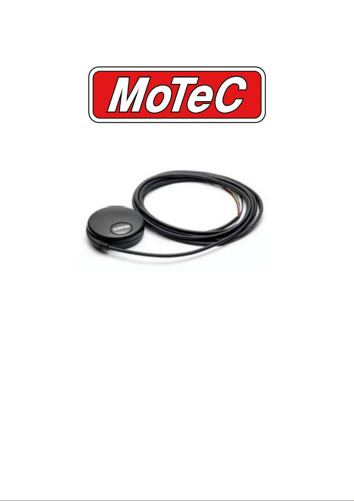
The GPS-G1 consists of a GPS unit with a built in antenna.
The units provide speed and position information, as well as altitude, heading,
date, time and GPS statistics.
The speed information can be used for display and logging purposes avoiding
the need for wheel speed sensors.
The position information can be used in the i2 data analysis software to create
track maps and to show and compare the driven lines.
Throughout this manual both the standard GPS-G1 version and the GPS-
G1(T) version will be referred to as GPS-G1 except where details specific to a
particular model are discussed.
Mounting
The GPS unit has an integrated antenna and should be mounted on an
external horizontal surface that has a clear view of the sky.
The unit should be mounted away from sources of interference including
other antennas.
If mounting on a non metallic surface it may be necessary to add a metallic
ground plane under the unit to improve the signal level. The ground plane
should be at least 150 mm (6 in) square and may be made of aluminium or
steel.
The unit has a magnetic mounting base and includes an M3 thread in the
centre.
Page 4

2 Using the GPS
Electrical Connections
The GPS unit sends data to the logging device via an RS232 serial
connection.
The wiring between the GPS connector and the logging device should be as
short as possible, preferably less than 1 m (3 ft)
The following table shows how to wire the GPS unit to a number of MoTeC
logging devices.
GPS
Pin
1
2
3
4
Note that the ADL2 and SDL logging devices only have one serial connection
therefore if an ECU is to be connected then it must be connected via CAN
(Note that not all ECUs have a CAN connection)
GPS
Name
Bat - Bat - 7 4 Bat- from VIM
TX RX 79 34 15
RX Not Used
5V 5V 18 etc 14 Requires 5V
Logging
Device
Name
ADL2 SDL ACL
from VIM
GPS Configuration
The GPS comes preconfigured from MoTeC to suit MoTeC's data loggers.
Page 5

MoTeC Using the GPS 3
Data Logger Configuration
Software Version
The Data Logger must be running the following software version (or higher)
SDL Version 1.3 or higher
ADL2 Version 4.4 or higher
ACL Version 1.1 or higher
Setup Requirements
• In the communications setup
o Select RS232 in the list then select GPS - Standard RMC GGA
template
o Change the baud rate to 19200 for GPS-G1
Change the baud rate to 38400 for GPS-G1(T)
• In the logging setup
o The following channels must be logged:
GPS Latitude, GPS Longitude, GPS Speed.
The other GPS channels are optional.
o The Logging Rate for all GPS channels should be set to 20 Hz
(even though the GPS is 5 Hz)
GPS Operation
In normal use the GPS unit should start operating within 15 to 45 seconds of
power up, however during first start-up or if the GPS has been moved to a
new location it may take up to 5 minutes before it gains satellite lock and
starts transmitting data.
To check that the GPS is operating correctly check the number of satellites
being received using the logging device Manager software.
The GPS requires a minimum of 4 satellites to function however normally the
GPS should see at least 7 satellites. If the GPS sees more satellites it will
improve accuracy and minimise satellite drop out.
Loss of signal may occur when the satellites are obscured by trees, buildings
or a bridge. The GPS will take a second or two to recover from this situation.
Page 6

4 Using the GPS
Data Analysis
GPS data analysis requires i2 data analysis software version 1.02 or higher.
All GPS channels (speed, heading, altitude etc) can be used in the usual way
including plotting on a graph etc.
The GPS position data (latitude and longitude) can also be used for the
following:
• To plot the actual path travelled on a GPS Track component.
o On the Add menu select GPS Track.
• To generate the conventional track map
o On Tools menu select Track Editor
o Select Generate Track and then GPS method.
• To plot the path travelled over a Google Earth image. (i2 Pro feature only)
o On the File menu select Google Earth Export.
Page 7

MoTeC Specifications 5
Specifications
Electrical
Power Supply Voltage 4.0 to 5.5 V
Power Supply Current 65 mA
Connections
Mating Connector Deutsch DTM06-4S
Pin Name Description
1 Bat - Connect to Battery Negative on the logging device
2 TX Connect to RX pin on logging device
3 RX Don't connect (This pin is only used for programming)
4 5V Connect to 5 V sensor supply on the logging device
Data
Output Type RS232
Output Levels 0 V / 5 V (nominal)
Baud Rate GPS-G1 19200 (MoTeC default)
Baud Rate GPS-G1(T) 38400
NMEA Sentences RMC, GGA (MoTeC default)
Physical
Antenna Built into GPS unit
Size 61 mm diameter x 19.5 mm (2.4" diameter x 0.77")
Weight 170 g (6.0 oz)
Cable length 4.5 m (15 ft)
Operating Temp -30 °C to +80 °C (-22 F to 176 F)
Mounting Magnetic base + M3 centre thread
GPS Performance
Update Rate 5 Hz
Satellite Channels 12
Reacquisition Time < 2 secs
Hot Start Time 15 seconds
Warm Start Time 45 seconds
Cold Start Time 5 minutes
Dynamics >4G
 Loading...