

Page 1

MoTeC E888/816 Manual
Contents
Introduction........................................................................ 1
Overview............................................................................. 2
Inputs.................................................................................. 3
Input Pin Configuration (ADL) .............................................................................4
Outputs............................................................................... 7
Output Configuration...........................................................................................7
E8xx Diagnostic Information.......................................... 11
Test Analogue Inputs........................................................................................12
Test Auxiliary Outputs.......................................................................................12
Communications.............................................................. 14
CAN..................................................................................................................14
Firmware Upgrades...........................................................................................14
Appendices....................................................................... 15
Appendix A: General Specifications..................................................................15
Appendix B: Input Characteristics.....................................................................16
Appendix C: Output Characteristics..................................................................18
Appendix D: CAN Wiring – Multiple Device.......................................................19
Appendix E: E8xx to ADL Wiring.......................................................................20
Appendix F: E8xx to M800 Wiring.....................................................................21
Appendix G: E888 Pin List by Pin Number........................................................22
Appendix H: E816 Pin List by Pin Number................................... .....................23
Appendix I: E816 Connector.............................................................................24
© Copyright 2005 – Motec Pty Ltd
The information in this document is subject to change without notice.
While every effort is taken to ensure correctness, no responsibility will be taken for the consequences of any
inaccuracies or omissions in this manual.
16 December, 2005
Page 2

Page 3

MoTeC Introduction 1
Introduction
This manual describes the functions and specifications of the E888/E816
expander modules and their configuration for use with a MoTeC ADL. These
devices offer additional inputs and outputs into the ADL v ia a CAN connection.
ECU Manager software is currently being developed that will allow the M800
family of ECUs to read information from the E888/816.
This manual includes information on connecting a single expander unit to an
ADL or ADL2. The ADL2 along with the ADL2 Dash Manager software has
been designed to easily allow the connection of a second expander.
It is possible to connect a second expander unit to an ADL and a third or even
fourth unit to an ADL2 – please contact your MoTeC dealer for details in these
situations.
The SDL is capable of reading data from 8 thermocouples when connected to
an E888. It cannot read analog voltage inputs.
Page 4
2 Overview
Overview
The E888 has the following inputs and outputs:
• 8 Analog voltage inputs (AV 1-8)
• 8 Thermocouple inputs (TC 1-8)
• 2 Cold junction compensation thermistor inputs (CJC 1-2)
• 4 Digital inputs (DIG 1-4)
• 2 Switch inputs (DIG 5-6)
• 8 PWM outputs (Aux 1-8)
The E816 has the following inputs and outputs:
• 16 Analog voltage inputs (AV 1-16)
• 2 Thermistor inputs (CJC1-2)
• 4 Digital inputs (DIG 1-4)
• 2 Switch inputs (DIG 5-6)
• 8 PWM outputs (Aux 1-8)
The E888 uses the two part 60 pin connector also used by the M400, M600
and M800 ECUs.
The E816 uses a 66 pin Autosport connector, the same as that used by the
M880 ECU.
Page 5

MoTeC Inputs 3
Inputs
E888 Thermocouple Inputs (TC1 – TC8)
The E888 has eight calibrated and compensated type K (-200 to 1250ºC)
thermocouple inputs. Thermocouple inputs are calibrated during production.
Note that the thermocouples numbered TC1 – TC8 correspond to pins AV9 –
AV16 in the Dash Manager Input pins setup.
Cold Junction compensations are performed using external sensors or the
E888 internal temperature sensor, according to the following rules:
• If only one of the two external cold junction compensation sensors (CJC1
or CJC2) is present then that sensor is used for compensations on all
thermocouple inputs.
• If both of the two external cold junction compensation sensors are present
then sensor CJC1 is used for compensations on TC1 to TC4, and sensor
CJC2 is used for compensations on TC5 to TC8.
• If neither of the two external cold junction compensation sensors are
present then the internal temperature sensor is used for compensations on
all thermocouple inputs.
Cold Junction Compensation Inputs (CJC1 and
CJC2)
The cold junction compensation inputs are used to measure thermistor (2 wire
temperature sensor) temperatures for thermocouple input compensation. If the
thermocouple inputs are not in use, or when using the E816, these inputs may
be used as general purpose temperature inputs.
CJC1/2 inputs have internal 1K pull-ups, and are calibrated to use Bosch 0 280
130 023/026 sensors to read from -30ºC to 150ºC.
Analog Voltage Inputs (AV1 – AV8 or AV1 – AV16)
The E888 has eight 0-5V analog voltage inputs (AV1 to AV8), while the E816
has sixteen inputs (AV1 to AV16). These are suitable for Potentiometers,
voltage output sensors and variable resistance (temperature) sensors (these
require an external pull-up resistor to 5V).
Page 6

4 Inputs
Digital Inputs (DIG1 – DIG 4)
DIG1 to DIG4 may be used to measure frequency. The frequency
measurement range is approximately 1Hz to 5000Hz. Digital inputs should be
pulled to ground as the inputs have an internal 2K7 to 12V pull-up resistor.
Note: Digital Inputs 1 – 4 can only be calibrated to measure frequency. If they
are used as On/Off switches, then the status information is available in the
CAN template ‘Expander Diagnostics’ – see below
Switch Inputs (DIG5 – 6)
These can be used to measure and On/Off style switch. The switches should
be wired so that the E8xx input is pulled to ground when the switch is activated.
Note: Digital inputs 5 and 6 are not included in the Input Pins setup. Instead
they are included in the CAN template ‘Expander Diagnostics’ – see below.
Input Pin Configuration (ADL)
Sensors connected to the E8xx inputs can be configured in the same way as
those connected directly to the ADL. This requires that the ADL is upgraded to
version 3.1 or later.
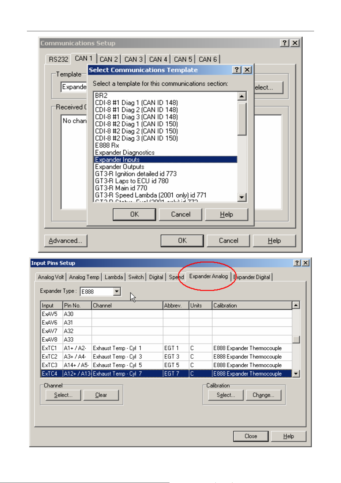
In Dash Manager, go to ‘Inputs – Communications’ and select an empty CAN
tab. Click on ‘Select’ and choose ‘Expander Inputs’ from the list.
Tabs for Expander Analog Volt and Expander Digital input pin configuration
can be found under the Dash Manager menu item ‘Inputs – Input Pins’.
The Expander type can be selected from the drop down list. The list of inputs
will then show the input name and pin numbers for that particular expander.
The 16 Analogue Volt and 4 Digital Inputs can now be configured the same
way as other ADL inputs by Selecting a channel and then assigning a
calibration. See the ADL Manual for more details on configuring sensor inputs.
Page 7
MoTeC Inputs 5
Page 8
6 Inputs
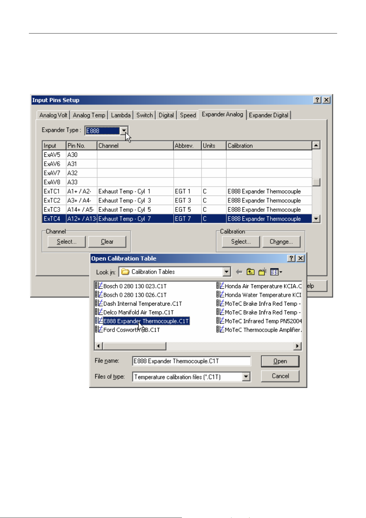
E888 Thermocouples
Thermocouple inputs 1 – 8 correspond to Expander Analog inputs ExTC1 to
ExTC8. The calibration used for these inputs is “E888 Expander
Thermocouple” and can be found in the ‘Select Calibration’ list.
Page 9

MoTeC Outputs 7
Outputs
Both the E888 and E816 include 8 Auxiliary Outputs that are individually
controllable for frequency and duty cycle. They are known as PWM – Pulse
Width Modulated – outputs.
The outputs are in two groups (odd and even) with different characteristics as
follows:
Duty cycle for PWM1/3/5/7 is adjustable from 0 to 100% in 255 steps.
Frequency for PWM1/3/5/7is adjustable from 8Hz to 5kHz.
Duty cycle for PWM2/4/6/8 is adjustable from 0 to 100% in 20 steps.
Frequency for PWM2/4/6/8 is adjustable from 1Hz to 100Hz.
The PWM outputs each have high and low side drivers. A duty cycle sent to the
E888 is the low duty cycle ie:
• an output with 100% duty cycle is pulled low
• an output with 0% duty cycle is pulled high
If the frequency for an output is set to 0, then the output is turned on/off
according to the following rules:
• For a duty cycle of 0%, the output is off (ie: pulled high)
• For a duty cycle greater than 0%, the output is on (ie: pulled low)
All outputs are disabled until the first CAN message is received.
Outputs are disabled after no CAN messages have been received for one
second.
Output Configuration
Auxiliary Devices connected to the E8xx outputs can be configured in the same
way as those connected directly to the ADL. This requires that the ADL is
upgraded to version 3.1 or later.
In Dash Manager go to ‘Inputs – Communications’ and select an empty CAN
tab. Click on ‘Select’ and choose ‘Expander Outputs’ from the list.
Page 10

8 Outputs
Page 11

MoTeC Outputs 9
The tab for Expander Output configuration can be found under the Dash
Manager menu item ‘Functions – Auxiliary Outputs’.
Page 12

10 Outputs
The E8xx outputs can now be configured the same way as the ADL Auxiliary
outputs by select ing an output and then setting the control channels and
parameters.
Ie: Outputs can be on/off, controlled by frequency, duty cycle or a combination
of frequency and duty cycle. Note that appropriate control channels will need to
be generated for these functions. See the ADL Manual for more details on
configuring outputs.
Page 13

MoTeC E8xx Diagnostic Information 11
E8xx Diagnostic Information
Additional status information is available from the E8xx along with the state of
the 2 Switch Inputs and the temperatures measured on the 2 thermistor inputs.
This information can be accessed by selecting an additional CAN template in
the Dash Manager communications setup.
Go to ‘Inputs – Communications’ and click on a blank CAN tab. Then ‘Select’
the template “Expander Diagnostics”.
Page 14

12 E8xx Diagnostic Information
Test Analogue Inputs
It is possible to view the current ‘live’ voltages on the expander’s analogue
inputs using a PC connected to the E8xx via an ADL. In Dash Manager select
the menu item ‘Online – Test – Analogue Inputs’. Then click on the tab
‘Expander Analog’. This is very useful for testing wiring and sensors, and even
determining which sensors are connected to which inputs.
Test Auxiliary Outputs
Similar to the ‘Test Analog Inputs’ function, this screen allows the Auxiliary
Outputs to be tested. In Dash Manager select the menu item ‘Online – Test –
Auxiliary Outputs’ then cl ick on the tab ‘Expander Outputs’.
To test an output select the desired output from the list then enter a suitable
Duty Cycle and Frequency then click the Start button.
Page 15

MoTeC E8xx Diagnostic Information 13
100% duty cycle corresponds to the output fully On (Low Voltage), 0% duty
cycle corresponds to the output fully Off (High Voltage). The frequency should
be chosen to suit the device.
Page 16

14 Communications
Communications
CAN
The CAN bus is used for PC communications during testing, calibration and
firmware upgrades, and for communicating to the ADL or M800.
The following data is transmitted by the E888/E816 at 200Hz:
• Thermocouple temperatures
• Analog input voltages
• Digital input frequencies
The following data is transmitted by the E888/E816 at 50Hz:
• Cold junction compensation temperatures
• Digital input states
• Output driver faults
• Internal temperature
• Internal voltages (-5v, 8vAux, 5vAux, Vbat, 4.5v)
• E888 status flags
• E888 firmware version
The following data is received by the E888/E816 from the ADL:
• PWM outputs frequency and duty cycle
• PWM outputs disable
Firmware Upgrades
At times MoTeC may release Firmware upgrades for the E8xx Expander units.
Upgrades are performed over the CAN bus using the Dashsend utility with a
MoTeC CAN cable.
The Dash Manager installation adds an icon to the Start menu to perform the
E888 firmware upgrade.
See the item under ‘Start – Programs – MoTeC – E888 and E816 Expander
Page 17

MoTeC Appendices 15
Appendices
Appendix A: General Specifications
Physical and Environmental
Case Size 99 x 105mm x 40mm
Weight E888 310g
E816 320g
Temperature Range -10 to 70°C
Power Supply
Operating Voltage 9 – 22V DC
Operating Current 150mA (excluding sensor currents and outputs)
Protection Battery transient protection
Reverse battery protection via external fuse
CAN Communications
CAN bus speed 1Mbit/s
No CAN terminating resistor onboard
Page 18

16 Appendices
Appendix B: Input Characteristics
K-Type thermocouple Inputs (E888)
Range -200 to 1250°C
Resolution 1°C
Accuracy (excluding cold junction errors):
• E888 case temperature 25°C, +/- 2°C Typical
• E888 case temperature -10 to 70°C, +/- 4°C + 2% measured
temperature
Filtering Oversampled for anti-aliasing
Update rate on CAN 100Hz (CAN address 0x0F0 or 0x0F8)
50Hz (CAN address 0x0F4 or 0x0FC)
Analog Voltage Inputs
Range 0 to 5V
Resolution 4.89mV (10bit conversion)
Input Resistance 100Kohms to 0V
Filtering Oversampled for anti-aliasing
Update rate on CAN 200Hz (CAN address 0x0F0 or 0x0F8)
50Hz (CAN address 0x0F4 or 0x0FC)
Internal Cold Junction Compensation sensor-
Resolution 1°C
Accuracy
• E8XX case temperature 25°C, +/- 2°C
• E8XX case temperature -10 to 70°C, +/- 4°C
External Cold Junction Compensation Inputs (Bosch
0 280 130 023/026)-
Range -30 to 150°C
Page 19

MoTeC Appendices 17
Resolution 1°C
Accuracy -10 to 70degC measured temperature, +/- 1°C + Sensor accuracy
Digital Inputs (Schmitt Trigger)
Pullup resistor 2700 ohms to 5V
Voltage range 0 to 15V
Positive trigger threshold 3.5V max
Negative trigger threshold 1.0V min
Hysteresis 0.5V min
Freq Range (for inputs 1-4) 1Hz to 6kHz
Freq Resolution (for inputs 1-4) 0.1Hz
Minimum Pulse Width 0.05mS
Update rate on CAN 200Hz (CAN address 0x0F0 or 0x0F8)
50Hz (CAN address 0x0F4 or 0x0FC)
Page 20

18 Appendices
Appendix C: Output Characteristics
Outputs
Current per output when using the given number of outputs:
• 1 Output 3.2A
• 2 Outputs 2.3A
• 4 Outputs 1.6A
• 8 Outputs 1.1A
Duty cycle resolution (high speed outputs) 255 steps (0-100%)
Frequency Range(high speed outputs) 8Hz to 5kHz
Duty cycle resolution (low speed outputs) 20 steps (0-100%)
Frequency Range (low speed outputs) 1Hz to 100Hz
Page 21

MoTeC Appendices 19
Appendix D: CAN Wiring – Multiple Device
The CAN bus should consist of a twisted pair trunk with 100R (0.25Watt)
terminating resistors at each end of the trunk.
The preferred cable for the trunk is 100R Data Cable but twisted 22# Tefzel is
usually OK.
The maximum length of the bus is 16m (50ft) including the MoTeC CAN Cable
(PC to CAN Bus Communications Cable)
CAN Devices (such as MoTeC ADL, BR2 etc) may be connected to the trunk
with up to 500mm (20in) of twisted wire.
The connector for the CAN Communications Cable may also be connected to
the trunk with up to 500mm (20in) of twisted wire and should be within 500mm
of one end of the trunk. If desired two CAN Cable connectors may be used so
that the MoTeC CAN Cable may be connected to either side of the vehicle.
Both connectors must be within 500mm of each end of the trunk.
100R Terminating
Resistors at each
end of the CAN Bus
CAN-HI
CAN-LO
100R
CAN-LO
CAN-HI
CAN Device
eg BR2
These w ires must be Tw ist ed
Minimum one twist per 50mm (2in)
500mm
<< CAN Bus >>
500mm
Max
CAN-LO
CAN-LO
CAN-HI
CAN Device
eg M800
CAN-HI
CAN Device
eg ADL
Max
CAN Cable
Connector
5
4
3
1
CAN-LO
CAN-HI
500mm Max
0V
8V
100R
Short CAN Bus
If the CAN Bus is less than 2m (7ft) long then a single termination resistor may
be used. The resistor should be placed at the opposite end of the CAN Bus to
the CAN Cable connector.
Page 22

20 Appendices
Appendix E: E8xx to ADL Wiring
E8xx
Ground
Power
CAN-LO CAN-LO
CAN-HI CAN-HI
See pin list
See pin list
B24 / 47
B23 / 54
Bat -
Bat +
7
8
73 or 75
74 or 76
Bat Bat +
ADL
0V
8V
71
72
CAN Cable
Connector
1
0V
2
3
8V
4
CAN-LO
5
CAN-HI
CAN-HI
CAN-LO
100R
See the CAN Bus
Wiring Specification
Any Other
CAN Device
Any Other
CAN Device
100R
for more Detail
E8xx Power and Ground Wiring
E888
E816
Additional Power and Ground pins are provided to simplify wiring and to meet
the current requirements of any devices connected to the PWM outputs.
Bat + Bat -
A17, B8, B9 A10, A11, B15, B16
28, 29, 30, 37, 38, 39 13, 14, 15, 19, 20, 21, 22
As a general principle, if no outputs are being used, then wiring one power and
one ground pin is sufficient. If the expander outputs are used, then all power
and ground pins should be wired up.
Page 23

MoTeC Appendices 21
Appendix F: E8xx to M800 Wiring
Note that this also applies to the M400, M600 and M880 ECUs.
E8xx
Ground
See pin list
Bat -
Bat +
ECU
CAN Cable
Connector
Power
CAN-LO CAN-LO
CAN-HI CAN-HI
CAN-HI
CAN-LO
100R
See pin list
B24 / 47
B23 / 54
See the CAN Bus
Wiring Specification
for more Detail
B24 / 47
B23 / 48
Any Other
CAN Device
E8xx Power and Ground Wiring
Bat + Bat -
71
0V
72
8V
Any Other
CAN Device
1
0V
2
3
8V
4
CAN-LO
5
CAN-HI
100R
E888
E816
A17, B8, B9 A10, A11, B15, B16
28, 29, 30, 37, 38, 39 13, 14, 15, 19, 20, 21, 22
Additional Power and Ground pins are provided to simplify and to meet the
current requirements of any devices connected to the PWM outputs.
As a general principle, if no outputs are being used, then wiring one power and
one ground pin is sufficient. If the expander outputs are used, then all power
and ground pins should be wired up.
Page 24

22 Appendices
Appendix G: E888 Pin List by Pin Number
The E888 uses a 34 + 26 pin connector pair with the following pin-out:
Pin Function Pin Function
A1 TC1+ B1 PWM1
A2 TC1- B2 PWM2
A3 TC2+ B3 PWM3
A4 TC2- B4 PWM4
A5 TC3- B5 PWM5
A6 CJC1 B6 PWM6
A7 CJC2 B7 PWM7
A8 B8 BATTERY +
A9 B9 BATTERY +
A10 BATTERY- B10 DIG2
A11 BATTERY- B11 DIG1
A12 TC4+ B12 DIG5
A13 TC4- B13 PWM8
A14 TC3+ B14 0V COMMS
A15 0V B15 BATTERYA16 8V B16 BATTERYA17 BATTERY+ B17
A18 TC5+ B18 DIG4
A19 TC5- B19 DIG3
A20 TC6+ B20 5V
A21 TC6- B21 0V
A22 AV1 B22 8V
A23 AV2 B23 CAN HI
A24 AV3 B24 CAN LO
A25 AV4 B25 DIG6
A26 TC7+ B26
A27 TC7-
A28 TC8+
A29 TC8-
A30 AV5
A31 AV6
A32 AV7
A33 AV8
A34 5V
Page 25

MoTeC Appendices 23
Appendix H: E816 Pin List by Pin Number
The E816 uses a 66 pin autosport connector with the following pin-out:
Pin Function
(E816B)
1 34 PWM8
2 PWM7 35 CJC1
3 PWM6 36 8V
4 37 BATTERY+
5 AV11 38 BATTERY+
6 AV10 39 BATTERY+
7 PWM5 40
8 41 DIGITAL IN 5
9 AV9 42 DIGITAL IN 6
10 43
11 AV12 44 AV14
12 0V COMMS 45 8V
13 BATTERY- 46 5V
14 BATTERY- 47 CAN LO
15 BATTERY- 48
16 PWM4 49 PWM3
17 CJC2 50
18 0V 51
19 BATTERY- 52 AV15
20 BATTERY- 53 5V
21 BATTERY- 54 CAN HI
22 BATTERY- 55
23 DIGITAL IN 1 56 PWM2
24 DIGITAL IN 2 57 AV16
25 58 AV1
26 AV13 59 AV2
27 0V 60 AV3
28 BATTERY+ 61 PWM1
29 BATTERY+ 62 AV4
30 BATTERY+ 63 AV5
31 64 AV6
32 DIGITAL IN 3 65 AV7
33 DIGITAL IN 4
Pin Function
(E816B)
66 AV8
Page 26

24 Appendices
Appendix I: E816 Connector
Mating Connector
Deutsch : AS6-18-35SN
Wire
Wire to suit connector : 22# Tefzel, Mil Spec : M22759/16-22
Crimp Tool
Crimp Tool : M22520/2-01
Positioner for Crimp Tool : M22520/2-07
• Note that the Crim p Cont acts are type 22D (this is needed to set the crimp
tool correctly)
Wire Stripping Tool
The following tool is recommended
Ideal Industries 45-2133 stripping tool with LB1195 wire stop.
Heatshrink Boots
Straight : Racychem 202K153, Hellermann 156-42-G
Right Angle : Racychem 222K153, Hellermann : 1156-4-G
Page 27

MoTeC Notes 25
Page 28

26 Notes
Page 29

MoTeC Notes 27
Page 30

28 Notes
 Loading...