

Page 1
ADR
- Configuration and Functionality
USER MANUAL
Page 2

ADR Functionality User Manual Installation
Contents
Installation ................................................................................................................................................................. 3
Dimensions ............................................................................................................................................................... 3
Configuration ............................................................................................................................................................. 4
Connection to the ADR .............................................................................................................................................. 4
Password Support ..................................................................................................................................................... 5
Device Configuration ................................................................................................................................................. 5
Device Configuration Buttons ................................................................................................................................ 6
General Tab .......................................................................................................................................................... 6
Events Tab ............................................................................................................................................................ 7
Communications Tab ............................................................................................................................................. 8
LEDs Tab ............................................................................................................................................................... 9
Firmware Upgrades .................................................................................................................................................. 10
Managing Events ..................................................................................................................................................... 11
Download Logged Events ........................................................................................................................................ 11
Regenerate Logged Events from the Image File....................................................................................................... 11
Erase logged events ................................................................................................................................................ 11
ADR Functional Reference ........................................................................................................................................ 12
LEDs ........................................................................................................................................................................ 12
Orientation .............................................................................................................................................................. 13
Event Triggering ...................................................................................................................................................... 14
Event Triggering Methods ................................................................................................................................... 14
Event Logging .......................................................................................................................................................... 16
GPS and Timekeeping .............................................................................................................................................. 17
Power ...................................................................................................................................................................... 18
Supercapacitor Charging ..................................................................................................................................... 18
Power Loss Handling ........................................................................................................................................... 18
USB Power ......................................................................................................................................................... 18
External 5V Power Supply ................................................................................................................................... 18
CAN Bus .................................................................................................................................................................. 19
Transmit Messaging ............................................................................................................................................ 19
Receive Messaging ............................................................................................................................................. 20
Faults ....................................................................................................................................................................... 21
Importing Events into MoTeC I2 Pro ......................................................................................................................... 22
Specifications .......................................................................................................................................................... 23
MoTeC — Published: 11 February 2014 Page 1
Page 3

ADR Functionality User Manual Installation
Communications ..................................................................................................................................................... 23
Connectors .............................................................................................................................................................. 23
Physical construction and dimensions ..................................................................................................................... 23
Power ...................................................................................................................................................................... 23
Operational .............................................................................................................................................................. 23
Connector and Pinout ............................................................................................................................................... 24
MoTeC — Published: 11 February 2014 Page 2
Page 4
ADR Functionality User Manual Installation
Installation
Mounting to a suitable surface is critical for reliable ADR operation and useful accident data. Install in accordance with
the following notes.
Note:
The ADR must be mounted with each side parallel to one of the 3 primary axes of the vehicle. There are 24 possible
mounting orientations. See the Orientation section on page 13 for more detail.
• It is recommended that the ADR is securely mounted on a rigid structural member, close to the driver’s seat.
Avoid mounting to sheet metal bodywork or other vibrating surfaces.
• The mounting location should allow the LEDs to be easily seen by the race crew, officials and emergency
personnel.
Dimensions
Figure 1 – Dimensions and mounting
MoTeC — Published: 11 February 2014 Page 3
Page 5
ADR Functionality User Manual Configuration
Configuration
The ADR Manager application is used to configure the ADR, upgrade the firmware, and carry out event management
activities such as downloading and erasing data.
Connection to the ADR
ADR Manager connects to a powered ADR unit over the CAN bus. The connection can be made through a MoTeC
UTC (USB to CAN), or through a MoTeC Ethernet connected logger or ECU wired on the same CAN bus as an ADR.
MoTeC Ethernet devices include ACL, ADL3, CDL3, SDL3, C185, C125 and M1 ECUs.
Note: To allow a connection through a MoTeC Ethernet device, the UTC connection setting accessed
via the Tools > Options menu must be disabled.
If the ADR being connected has a password set, the password prompt is displayed. The correct password must be
entered before any other operations can be performed.
When an ADR is connected, a summary of the logged events is listed as shown in figure 2. The connection status and
ADR serial number are shown in the ADR Manager Status bar.
Connection
status
Figure 2 – Example ADR Manager window on connection to an ADR
Serial
number
MoTeC — Published: 11 February 2014 Page 4
Page 6
ADR Functionality User Manual Configuration
Password Support
An ADR unit can be password protected to prevent unauthorised access to all ADR features (configuration, upgrading
and event management).
Note:
A password can only be set on an ADR that does not have an existing password. If you want to change a password,
first clear it and then set a new password.
To set a password:
1. Select Device > Set Password menu option.
2. Enter the new password as directed.
To clear a password:
1. Select Device > Clear Password menu option.
Device Configuration
To configure the ADR:
1. Select the Device > Edit Configuration menu option.
Initially the Device Configuration window displays the configuration retrieved from the connected ADR. The
configuration may then be edited or loaded from disk.
Figure 3 – Example Device Configuration window
Note:
Viewing, editing, saving or loading a configuration from disk is all performed via the Device Configuration window.
2. Use the information that follows to perform the required configuration activities.
MoTeC — Published: 11 February 2014 Page 5
Page 7

ADR Functionality User Manual Configuration
Device Configuration Buttons
The Load, Save, Send and Close buttons are used to perform the following functions:
Load Load an existing configuration to the ADR Manager from disk.
Save Save the current configuration in the ADR Manager. This does not apply the configuration to the
ADR.
Send Apply the configuration to the ADR. The ADR configuration remains unchanged until another
configuration is sent.
Close Closes the Device Configuration window.
General Tab
See Figure 3, the function of the parameters on the General tab is as follows.
Identity/Name Optional name for the ADR.
Mounting Orientation The orientation of the installed ADR must be specified. This allows the
accelerometer readings to be correctly aligned to the vehicle. See the Orientation
section on page 13 for more detail.
Supercapacitor
Recharge/Recharge Rate
The rate determines how fast the super capacitor is charged. The maximum rate
(100%) is recommended for most applications.
The higher the charge rate, the quicker the supercapacitor reaches full charge.
See the Power section on page 18 for more detail.
MoTeC — Published: 11 February 2014 Page 6
Page 8
ADR Functionality User Manual Configuration
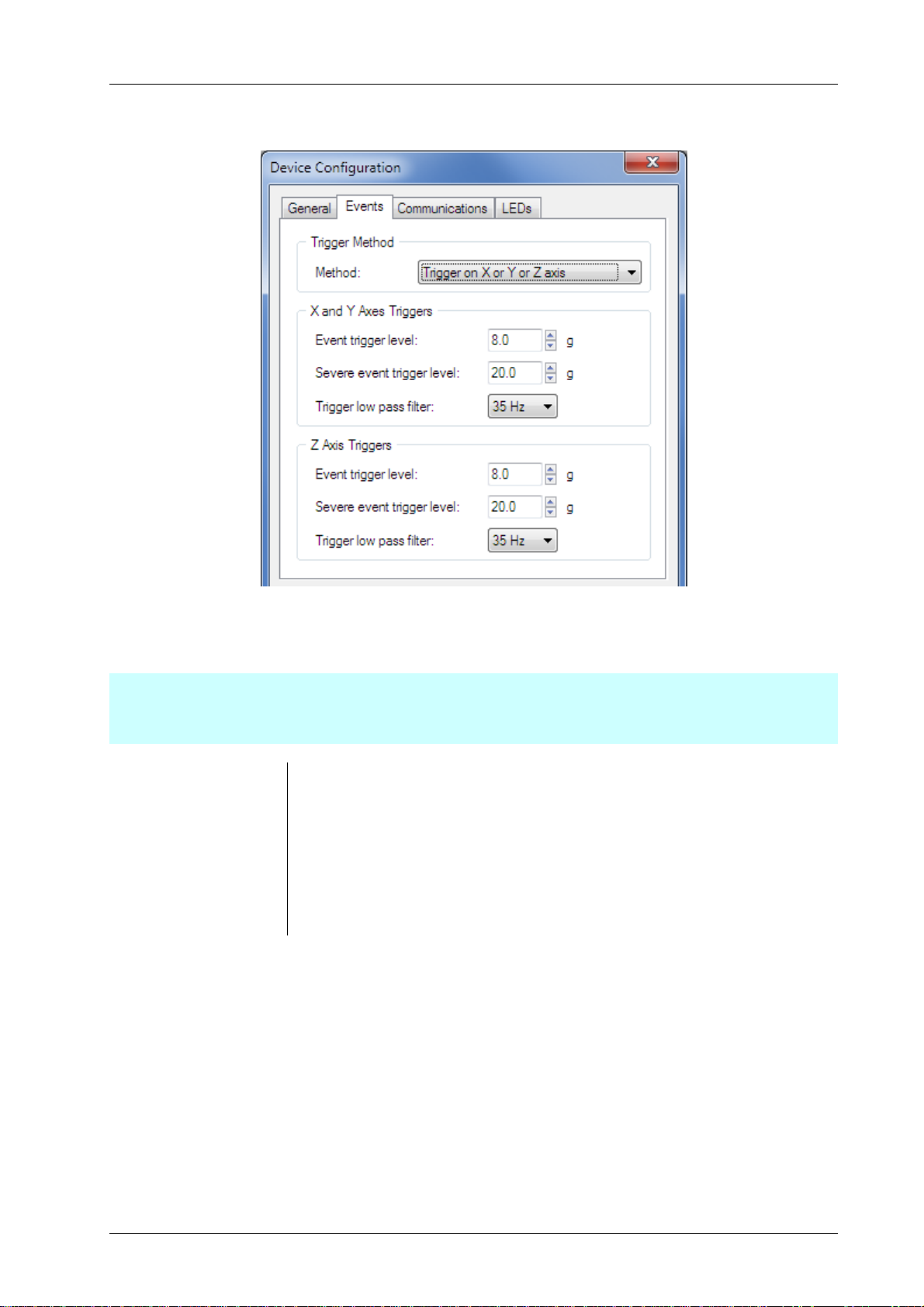
Events Tab
Figure 4 – Device Configuration – Example Event Tab
The functions of the parameters on the Events tab are as follows.
Important:
Before selecting triggering methods and thresholds it is important to have a good understanding of event triggering.
Read Event Triggering on page 14 before configuring triggering.
Trigger Method Determines how the three axes of acceleration are used in triggering.
Event trigger level Threshold for triggering event logging.
Severe event trigger level Threshold for treating a logged event as a severe event.
Trigger low pass filter Sets the level of filtering applied to the accelerometer output before used in
event triggering.
MoTeC — Published: 11 February 2014 Page 7
Page 9

ADR Functionality User Manual Configuration
Communications Tab
Figure 5 – Device Configuration – Example Communications Tab
The functions of the parameters on the Communications tab are as follows.
CAN Transmit (base)
Address
CAN Receive (base) Address This is the first of the five sequential addresses used by the ADR for receiving
Further Information:
See the CAN Bus section on page 19 for more detailed information on CAN messaging.
GPS / Enable Receive Used to enable or disable GPS reception. Disabling the GPS will prevent the
GPS baud rate This can be set to 9600, 19200, 38400, 57600 or 115200.
Further Information:
See the GPS and Timekeeping section on page 17 for more detailed information on GPS communications.
This is the first of the two sequential addresses used for by the ADR for
transmitting status messages.
CAN channels.
GPS diagnostic bits (in the CAN status messages) from being set.
MoTeC — Published: 11 February 2014 Page 8
Page 10

ADR Functionality User Manual Configuration
LEDs Tab
Figure 6 – Device Configuration – Example LEDs Tab
The Intensity of each of the three LEDs on the ADR can be individually configured.
The functions of the parameters on the LEDs tab are as follows.
LED Intensity / Status /
Power/ Data
External LED / Enable
external LED
External LED / Duty Used to set the brightness of the external LED during the power on lamp test.
Further Information:
For details on how the LEDs function; see the LEDs section on page 12.
Used to set the brightness (1% to 100%).
Enable or disable the external LED function. Disable this function if an external
LED is not used. If not disabled, and an external LED is not used, an External
LED open circuit fault is generated.
MoTeC — Published: 11 February 2014 Page 9
Page 11

ADR Functionality User Manual Firmware Upgrades
Firmware Upgrades
Update the ADR firmware and bootloader through ADR Manager as follows.
1. Select the Device > Update Firmware menu option.
The Update Firmware window displays showing the firmware and bootloader versions loaded on the ADR and the
versions on disk.
2. Select the Update button if you want to update the firmware and bootloader on the ADR.
Figure 7 – Example Update Firmware window
MoTeC — Published: 11 February 2014 Page 10
Page 12

ADR Functionality User Manual Managing Events
Managing Events
Download Logged Events
A summary of available logged events is shown in the MoTeC ADR Manager window whenever an ADR is connected,
see Figure 2.
The destination folders for downloaded event files (.CSV) and log image files (.mtcadrimg) can be configured via the
Tools > Options menu.
To download all events from the ADR (cannot download individual events):
1. Select the Events > Download menu option.
The downloaded events are stored in a single log image file (.mtcadrimg). When the download is complete, the
individual event files (.CSV) are generated and a summary of created folders and files is displayed.
Notes on the event files (.csv):
• An individual event file (.csv) is created for each event that was downloaded.
• The file name contains the event time, date, ADR serial number and a sequence number, as shown in the
following example.
ADR_LOG_SN11_20130124_135734_001.CSV
_SN11 ADR serial number 11
_20130124 Event date Jan 24 2013
_135734 Event time 13:57:34 (UTC)
_001 Unique sequence number, incremented each time the same event file is generated.
Notes on the log image files (.mtcadrimg):
• The log image file name contains the ADR serial number and a sequence number. The sequence number is
incremented each time the log image is downloaded for the same ADR serial number.
• The log image file contains all the downloaded events on the ADR, and the ADR configuration at the time of
download.
• The event files can be regenerated from this log image at any time.
Regenerate Logged Events from the Image File
1. Select File > Convert Logging Image menu option in ADR Manager.
Erase logged events
1. Select Events > Erase menu option.
ADR Manager prompts to confirm the action and then erases all logging from the ADR.
MoTeC — Published: 11 February 2014 Page 11
Page 13

ADR Functionality User Manual ADR Functional Reference
ADR Functional Reference
LEDs
LED settings can be changed using the Device Configuration function; see the LEDs Tab section on page 9.
Status LED
(Red)
Power LED
(Green)
Data LED
(Blue)
External LED The External LED pin is a 30mA constant current output. The LED output has a clamp circuit to
• Turned ON at the configured brightness for 2 seconds after application of power (battery
voltage or USB power).
• Turned ON at the configured brightness if a fault is detected.
• Pulsed at full brightness for a 10ms flash once per second if any severe event is present in the
logged events.
Note:
If power is lost during an event, the ADR uses a supercapacitor to maintain power for event
logging and severe event indication.
• Turned ON when external power (battery voltage or USB power) is present.
• Turned ON at the configured brightness if any events are logged.
• Flashes at 1Hz if the event log is full.
• Flashes at 6Hz if an event is in progress.
protect the ADR if the output is open circuit. The output can drive a single LED or series chain of
LEDs with a maximum forward voltage of 10V.
• Turned ON as a lamp test at the configured duty for 2 seconds after application of power
(battery voltage or USB).
• Pulsed at full brightness for a 10ms flash once a second if any severe event is present in the
log.
• If the External LED is enabled in the configuration, then an open circuit test will be performed
during the lamp test. The external LED is considered open circuit if the LED driver output
voltage exceeds 11V.
If an open circuit fault is detected during the lamp test, then the External LED output is
disabled until the next power on lamp test.
If a severe event is present and the External LED is configured, the ADR will still attempt to
flash the External LED, even if an open circuit fault has been detected.
MoTeC — Published: 11 February 2014 Page 12
Page 14

ADR Functionality User Manual ADR Functional Reference
Y
Orientation
The ADR may be installed in one of the 24 possible mounting orientations that align with the primary axes of the
vehicle.
The 24 mounting orientations are defined in the following table.
Connector faces back X X X X
Connector faces front X X X X
Connector faces up X X X X
Connector faces down X X X X
Connector faces left X X X X
Connector faces right X X X X
Figure 8 – Example Mounting Orientation (connector faces back, LEDs face up)
The readings from the three axes of the accelerometer are always aligned to a default vehicle orientation.
LEDs face
back
LEDs face
front
LEDs face
up
LEDs face
down
LEDs face
left
LEDs face
right
+Z
+
+X
Figure 9 – Default Vehicle Orientation
Notes:
• All references to the X, Y and Z axes in triggering setup, and logging and CAN outputs, refer to the default vehicle
orientation.
• The installed orientation must be specified using the Device Configuration function; see the General Tab section
on page 6.
MoTeC — Published: 11 February 2014 Page 13
Page 15

ADR Functionality User Manual ADR Functional Reference
Event Triggering
The readings from the three axes of the accelerometer pass through several levels of low pass filtering before being
used for triggering and logging.
Event Triggering can be set using the Device Configuration function; see the Events Tab section on page 7. The event
triggering flow is as shown below.
Accelerometer Internal filter
nd
(400Hz 2
Analogue anti-aliasing filter
(400Hz 2
Software filter
(250Hz 4
order Bessel)
nd
order Bessel)
th
order Butterworth)
Event Log
Log file containing:
‐ Raw log readings
‐ Log readings filtered to CFC60
‐ Log readings filtered with the user configurable trigger filter
Event Triggering Methods
User configurable trigger filter
(5Hz-100Hz 2
Event triggering against user configurable
thresholds
nd
order Butterworth)
ADR Device
PC (ADR Manager)
Software filter for CFC60
nd
order Butterworth
100Hz 2
Figure 10 – Flow of Event Triggering
User configurable trigger filter
(5Hz-100Hz 2
nd
order Butterworth)
The ADR can be configured to use one of three event triggering methods:
The XYZ Vector is the recommended trigger method. A trigger method with separate Z axis settings can be useful in
situations where large Z axis accelerations such as curb impacts are expected.
Trigger on XYZ Vector
An event is triggered when the magnitude of the XYZ acceleration vector exceeds the Event Trigger Level.
The event is marked as a severe event when the magnitude of the XYZ acceleration vector exceeds the Severe Event
Trigger Level.
The same trigger filter settings are used for all axes.
MoTeC — Published: 11 February 2014 Page 14
Page 16

ADR Functionality User Manual ADR Functional Reference
Trigger on XY Vector or Z axis
An event is triggered when either:
• The magnitude of the Z acceleration exceeds the Z Axis Event Trigger Level, or
• The magnitude of the XY acceleration vector exceeds the XY Vector Event Trigger Level.
An event is considered as a severe event when either:
• The magnitude of the Z acceleration exceeds the Z Axis Severe Event Trigger Level, or
• The magnitude of the XY acceleration vector exceeds the XY Vector Severe Event Trigger Level.
The trigger filter setting used for the Z axis is separately configurable to the setting used for the X and Y axes.
Trigger on X or Y or Z axis
An event is triggered when either:
• The magnitude of the Z acceleration exceeds the Z Axis Event Trigger Level, or
• The magnitude of the X or Y acceleration exceeds the X and Y Axes Event Trigger Level.
An event is considered as a severe event when either:
• The magnitude of the Z acceleration exceeds the Z Axis Severe Event Trigger Level, or
• The magnitude of the X or Y acceleration exceeds the X and Y Axes Severe Event Trigger Level.
The trigger filter setting used for the Z axis is separately configurable to the setting used for the X and Y axes.
General Notes on Triggering:
• The event trigger starts the event logging process. The log contains 2 seconds of pre-trigger data and 30 seconds
of post-trigger data.
• The log files generated by ADR Manager contain the trigger filter output that was used to trigger the event. These
readings can be used to determine suitable filtering and thresholds.
MoTeC — Published: 11 February 2014 Page 15
Page 17

ADR Functionality User Manual ADR Functional Reference
Event Logging
Note:
If power is lost during an event, the ADR uses a supercapacitor to maintain power for event logging and severe event
indication (flashing Status LED).
The following applies:
• The ADR can store up to 10 events in non-volatile flash memory.
• Each event contains 2 seconds of pre-trigger data and 30 seconds of post trigger data.
• The stored event contains:
o Accelerometer readings (3 axes), updated at 1000Hz.
o CAN bus channels (20 channels), updated at 100Hz.
o GPS speed, date, time and location (lat/long), updated at 20Hz.
• The ADR always attempts to maintain free space so that a new event can be logged.
• Whenever there are more than 8 logged events, the oldest non-severe event in the event log will be
automatically erased to free the log location for new events. Severe events are never automatically erased.
• Logging can be downloaded and erased using ADR Manager; see the Events Tab on page 7.
The generated log file for a stored event contains the following channels:
Channel Name Update Rate Description
X (G)
Y (G)
Z (G)
CFC60 X (G)
CFC60 Y (G)
CFC60 Z (G)
Trigger X (G)
Trigger Y (G)
Trigger Z (G)
Trigger XY Vector (G)
Trigger XYZ Vector (G)
GPS Time (H)
GPS Time (M)
GPS Time (S)
1000Hz Filtered accelerometer readings as logged by the ADR
1000Hz Filtered accelerometer readings with further post-filtering to the
SAE J211 CFC60 crash test standard
1000Hz Filtered accelerometer readings used for event triggering
1000Hz Acceleration vector magnitude of the filtered readings used for
event triggering
1000Hz Time (UTC), set by the time received on the GPS input
GPS Speed (km/h)
GPS Latitude (°)
GPS Longitude(°)
Engine Speed (rpm)
Throttle Pedal Position (%)
Brake Pressure Front (kPa)
Brake Pressure Rear (kPa)
MoTeC — Published: 11 February 2014 Page 16
20Hz Speed and location received on the GPS input
100Hz Optional channels from received CAN messages
Page 18

ADR Functionality User Manual ADR Functional Reference
Channel Name Update Rate Description
Wheel Speed FL (km/h)
Wheel Speed FR (km/h)
Wheel Speed RL (km/h)
Wheel Speed RR (km/h)
Steering Angle (°)
Steering Position (mm)
User 1 to User 10
The log file additionally contains a header with the following information:
• Event date and start time (UTC) received on the GPS input
• ADR name (from the ADR configuration)
• ADR serial number
Note:
All references to X, Y and Z readings refer to the default vehicle orientation described in the Orientation section on
page 13.
Further Information:
See the Event Triggering section on page 14 for details on accelerometer filtering.
See the Receive Messaging section on page 20 for details of CAN channels.
GPS and Timekeeping
The ADR can receive time, speed and location data from NMEA GPRMC sentences transmitted over RS232 from a
GPS receiver. The GPS data is used to provide time and location stamping of ADR events, and to include vehicle speed
during event logging.
For information on enabling and configuring the GPS; see the Communications Tab section on page 8.
The following applies:
• If a GPS is not connected to the ADR, then the GPS functionality should be disabled in the device configuration to
prevent GPS faults.
• The RS232 baud rate can be specified in the device configuration to 9600, 19200, 38400, 57600 or 115200.
• The ADR maintains time and date only when powered on. The time stamping clock starts at 00:00 1/1/2000
when the ADR is turned on. The clock is set to the correct UTC time whenever a valid GPRMC sentence is
received from the GPS.
• GPS diagnostics are transmitted in the CAN status messages; see the CAN Bus section on page 19.
• If a received GPS sentence has an invalid checksum, then the data is ignored and the GPS Invalid diagnostic
status is set until a valid sentence is received.
• If no valid GPS sentence is received for 2 seconds then the GPS Timeout and GPS Invalid diagnostics statuses are
set until a valid sentence is received.
• The ADR provides 5V external power for a GPS receiver.
MoTeC — Published: 11 February 2014 Page 17
Page 19

ADR Functionality User Manual ADR Functional Reference
Power
If power is lost during an event, the ADR uses a supercapacitor to maintain power for event logging and severe event
indication (flashing Status LED).
Supercapacitor Charging
The following applies:
• Continuously charged when the ADR is powered from the battery voltage input (BATT+).
• Charge rate can be specified in the device configuration; see the General Tab section on page 6.
The higher the charge rate, the quicker the supercapacitor reaches full charge.
• It is recommended to use the maximum charge rate, except in specialised applications that require low current
draw from the ADR on start up.
Note:
With the maximum charge rate configured, the supercapacitor is charged to full capacity in less than one minute.
At this charge rate, the current drawn during charging from a 12V power source is less than 600mA.
Power Loss Handling
If the battery power is lost, the ADR enters a lower power utilisation mode to conserve supercapacitor power. The
CAN interface, GPS input and external 5V supply are disabled, and the Power and Data LEDs are turned OFF. Events
are still triggered and logged while enough power remains in the supercapacitor.
If the ADR has a severe incident already logged and the battery power is lost, and if no event logging is currently in
progress, then the ADR enters an extreme low power utilisation mode. This mode allows the Status and External LEDs
to flash for several minutes.
USB Power
During operation with ADR Manager, the ADR can be optionally powered by USB.
Note:
The supercapacitor is not charged when the ADR is powered by USB.
External 5V Power Supply
An external 5V power supply pin is provided to power a GPS receiver. The 5V supply is current limited to 90mA.
MoTeC — Published: 11 February 2014 Page 18
Page 20

ADR Functionality User Manual ADR Functional Reference
CAN Bus
The CAN bus is used for:
• Configuration, firmware upgrade and event download through ADR Manager.
• Transmission of ADR status.
• Receiving external channels to be stored in the event log.
Transmit Messaging
There are two status messages transmitted from the ADR at 50Hz on user configurable CAN Ids:
CAN Address Bytes Description Units
Transmit Address
(default 0x448)
Transmit Address + 1 0 Number of logged events
0:1 X axis 0.1G
2:3 Y axis 0.1G
4:5 Z axis 0.1G
6:7 Battery voltage mV
1 Event status bits:
0x01 Event in progress
0x02 Events logged
0x04 Severe Event logged
0x08 Event Log full
2 Supercapacitor charge level 1%
4:5 Diagnostic Bits:
0x0001 GPS data invalid
0x0002 GPS timed out
0x0004 CAN receive timed out
6:7 Fault Bits:
0x0001 Corrupt calibration
0x0002 Corrupt or invalid configuration
0x0004 Accelerometer self-test failed
0x0008 Logging memory test failed
0x0010 External LED open circuit
0x0020 Oscillator failed
0x0100 Voltage rail fault (2.3V rail)
0x0200 Voltage rail fault (5.5V rail)
0x0400 Voltage rail fault (3.0V rail)
0x0800 Voltage rail fault (5V rail)
0x1000 Voltage rail fault (5V CAN rail)
0x2000 Voltage rail fault (5V external rail)
MoTeC — Published: 11 February 2014 Page 19
Page 21

ADR Functionality User Manual ADR Functional Reference
Receive Messaging
The ADR receives up to five CAN messages starting at the user configured Receive Address.
During an event, the data in the received CAN messages is logged as 20 individual 16bit channels at 100Hz. These
logged channels are included in the log files generated by ADR Manager.
If the CAN connection is lost, the last received values continue to be logged.
The channels are labelled and scaled in the log file with the following channel names and scaling:
CAN Address Bytes Name Units Scaling of 16bit
data
Receive Address
(default 0x440)
Receive Address + 1 0:1 Wheel Speed FL Km/h Data / 10 1
Receive Address + 2 0:1 Steering Angle deg Data / 10 1
0:1 Engine Speed Rpm Data*6 0
2:3 Throttle Pedal Position % Data / 10 1
4:5 Brake Pressure Front kPa Data * 1 0
6:7 Brake Pressure Rear kPa Data * 1 0
2:3 Wheel Speed FR Km/h Data / 10 1
4:5 Wheel Speed RL Km/h Data / 10 1
6:7 Wheel Speed RR Km/h Data / 10 1
2:3 Steering Position mm Data / 100 2
4:5 User 1 Data * 1 0
Decimal
places
6:7 User 2 Data * 1 0
Receive Address + 3 0:1 User 3 Data * 1 0
2:3 User 4 Data * 1 0
4:5 User 5 Data * 1 0
6:7 User 6 Data * 1 0
Receive Address + 4 0:1 User 7 Data * 1 0
2:3 User 8 Data * 1 0
4:5 User 9 Data * 1 0
6:7 User 10 Data * 1 0
MoTeC — Published: 11 February 2014 Page 20
Page 22

ADR Functionality User Manual Faults
Faults
Various fault conditions are monitored by the ADR. The presence of a fault is indicated by the Status LED, and the fault
information is transmitted in the CAN status messages.
The following checks are performed.
Fault check Description
External LED open
circuit fault
Calibration and
configuration faults
Internal faults Whenever the ADR is restarted, the internal accelerometer, flash memory and oscillator
Internal voltage rail
faults
The external LED open circuit test is performed only during the power ON lamp test (on
application of power to an unpowered ADR).
See the LEDs section on page 12 for more detail on the lamp test.
If an external LED is not used with the ADR then the external LED output should be disabled
in the configuration; see the LEDs Tab section on page 9.
Whenever the ADR is restarted, the integrity of the stored calibration and configuration are
checked.
tests are performed.
The internal voltage rails are constantly monitored for correct voltage.
MoTeC — Published: 11 February 2014 Page 21
Page 23

ADR Functionality User Manual Importing Events into MoTeC I2 Pro
Importing Events into MoTeC I2 Pro
The .csv event files generated by ADR Manager can be imported into the MoTeC i2 Pro tool for conversion to MoTeC
.ld format log files and analysis.
Note:
To import .csv files into i2 Pro, the Import MoTeC CSV Dataset feature license must be installed in i2 Pro. The MoTeC
.ld files generated by i2 Pro can then be viewed on any installation of i2 Pro.
To import CSV files:
1. Open i2 Pro and create a new project or open an existing project.
2. Select the File > Import Data menu option to start the File Conversion Wizard.
a. Set the File Type to MoTeC CSV Dataset (*.csv).
b. Select the csv file as the input file.
c. Press the Next button to display the Unit Mappings window.
3. Press the Convert button to begin the conversion and display the conversion summary.
4. Tick the Open Converted Files On Finish box
5. Press the Finish button to close the Wizard and open the log file
Note:
The .ld files generated by the import process will be in the same folder as the csv file.
MoTeC — Published: 11 February 2014 Page 22
Page 24

ADR Functionality User Manual Specifications
Specifications
Communications
• CAN
• RS232 (for GPS receive)
• USB (for future use)
Connectors
• 1 x 11 pin double density size 8 Autosport connector
• Matching connector: MoTeC #68109 - Autosport double density female (red)
Physical construction and dimensions
• Case size (mm): 73.5 x 45 x 27
• Case material: anodized aluminum
• Internal components encapsulated
• Weight (gram): 110
Power
• Power supply (vehicle battery): 6 – 30V
• Current: 1A peak, 200mA steady state
• USB power when connected to PC (if no other power source)
• Backup power (internal super capacitor): 30 seconds of logging and 10 minutes of LED operation when power
supply lost (no battery required)
• Backup power recharge: under one minute after connection to a power source
Operational
• G force recording of lateral, longitudinal and vertical channels at 1000Hz
• Recording of up to 20 CAN channels at 100Hz
• G force range: -150G to +150G
• G force channel resolution: 0.1G
• GPS data recorded:
o Date and time
o Latitude and Longitude
• Pre-event (accident) recording duration: 2 seconds
• Event duration: 30 seconds
• Event capacity storage: 10 events
• Data output format: CSV
MoTeC — Published: 11 February 2014 Page 23
Page 25

ADR Functionality User Manual Connector and Pinout
Connector and Pinout
Connector: 11 pin double density Autosport size 8.
Figure 11 – Connector pinout, loom-side view
Pin Function Notes
1 Battery Negative
2 Battery Positive 6 to 30V DC
3 CAN-Lo
4 CAN-Hi
5 RS232-Rx
6 USB 5V
7 USB D- For future use
8 USB D+ For future use
9 USB 0V
10 LED Output Status output
11 5 Volt Supply Output GPS power supply 90mA
MoTeC — Published: 11 February 2014 Page 24
 Loading...