

Page 1

UserManual
®
BeCOMS
BCom | Bearing Condition Monitoring
Part No.: 1 900 00 00000
Release: 130301
(revision 190211)
Page 2

Page 3
Declaration of Conformity
®
/ BCom
EN 61000-4-5, EN 61000-4-6, EN 61000-4-8
EMC-Directives: 2014/30/EU
Manufacturer motcom® GmbH
Kurt-Schumacher-Str. 28-30
D - 66130 Saarbrücken / Germany
Phone +49 681 8837904-0
Fax: +49 681 8837904-19
We declare on our own responsibility, that the products
Product description motcom®
Bearing Condition monitoring
motcom® BeCOMS® | BCom
User Manual
Type designations BeCOMS
®
/ BCom
are in compliance with following norms:
EN 55011:2018-05/CISPR 11:2015 mod.+A1:2017
EN 55032/CISPR 22
EN 61000-4-2, EN 61000-4-3, EN 61000-4-4
EN 61000-4-5, EN 61000-4-6, EN 61000-4-8
66130 Saarbrücken, Germany, 2019, the 11th of February
Dipl.-Ing. Dieter Lott
Managing Director
Release 130301 (revision 190211)
Page iii
Page 4
motcom® BeCOMS® | BCom
User Manual
Note: This User Manual is applicable for BeCOMS® and BCom.
i
To simplify this manual we oen named gures and pictures with BCom,
but always follow the instruction and information for BeCOMS too.
!
!
It is recommended to read this manual before commencing the repair, assembly
or commissioning of the Bearing Condition monitoring system!
Caution: The manufacturer’s warranty will become void if these instructions are
not followed!
Page iv
Release 130301 (revision 190211)
Page 5

motcom® BeCOMS® | BCom
User Manual
Contents
1. System Description....................................................................... 1.1
2. Installation .................................................................................... 2.1
3. Commissioning ............................................................................. 3.1
4. Performance / Maintenance Tests ................................................ 4.1
5. Troubleshooting ............................................................................ 5.1
6. Repair ........................................................................................... 6.1
7. Spare Parts................................................................................... 7.1
8. Attachments .................................................................................. 8.1
Release 130301 (revision 190211)
Page v
Page 6

motcom® BeCOMS® | BCom
User Manual
Page vi
Release 130301 (revision 190211)
Page 7

motcom® BeCOMS® | BCom
User Manual
Contents
1. System Description....................................................................... 1.1
1.1. Components .............................................................................................1.1
1.1.1. BCom- Principle ................................................................................1.1
1.1.2. BCom- System Overview ..................................................................1.4
1.1.3. BCom- System Components ............................................................1.6
1.1.3.1. BCom Evaluator .........................................................................1.6
1.1.3.2. Connectors and pin-out of the BCom Evaluator ........................1.9
1.1.3.3. BCom Slip Ring Encoder (SRE) ..............................................1.10
1.1.3.4. Technical Data of BCom Slip Ring Encoder and Evaluator ..... 1.11
1.1.4. Editions of BCom System ...............................................................1.12
1.1.5. Versions of BCom System ..............................................................1.13
1.1.6. Intended Purpose of the Monitoring Software (opt.) .......................1.14
2. Installation .................................................................................... 2.1
2.1. General ....................................................................................................2.1
2.2. Installation Position ..................................................................................2.2
2.3. SRE Mechanical Adjustments ..................................................................2.3
2.4. Wiring Diagram ........................................................................................2.4
2.5. Software Installation (optional) .................................................................2.5
2.6. PC Requirements (optional) .....................................................................2.6
3. Commissioning ............................................................................. 3.1
3.1. Pre-Commissioning Checks .....................................................................3.1
3.2. Syncronization of the BCom Sensor with the ring TDC
of the rst cylinder ....................................................................................3.2
3.3. Data Sampling ..........................................................................................3.3
3.4. Alarm Setting and Triggering ....................................................................3.4
3.4.1. Alarm Resetting ................................................................................. 3.6
3.5. Settings & Parameters / Using the Evaluator ...........................................3.7
3.5.1. Basic Usage of the Evaluator ............................................................3.7
3.6. Menu Structure .........................................................................................3.8
3.6.1. System measured values 1 (default screen) .....................................3.8
3.6.2. System measured values 2 ...............................................................3.8
3.6.3. Graphic overview ..............................................................................3.9
3.6.4. SRE advanced infos .........................................................................3.9
3.6.5. Parameter setup .............................................................................3.10
Release 130301 (revision 190211)
Page vii
Page 8

motcom® BeCOMS® | BCom
User Manual
3.7. BCom Logger measurement data storage and management (optional) 3.16
3.7.1. Compressing Data Files ..................................................................3.17
3.7.2. Capturing the Graphic Screens .......................................................3.19
3.7.3. Archiving the Compressed Files .....................................................3.20
3.7.4. Manual Data Analysis for Compartment Localization .....................3.21
4. Performance / Maintenance Tests ................................................ 4.1
4.1. Function Test ............................................................................................4.1
5. Troubleshooting ............................................................................ 5.1
5.1. During Software Installation .....................................................................5.1
5.2. During Software Use ................................................................................5.2
5.3. Missing Control Signal .............................................................................5.3
5.4. Very low / strong signal on polar diagram ................................................5.4
5.5. Error code and Error description ..............................................................5.5
6. Repair ........................................................................................... 6.1
7. Spare Parts................................................................................... 7.1
7.1. Main Spare Parts .....................................................................................7.1
7.2. Accessories ..............................................................................................7.2
8. Attachments .................................................................................. 8.1
8.1. Connection Assembly Instructions ...........................................................8.1
8.1.1. Preparing the Cable ..........................................................................8.1
8.1.2. Connecting the RS-485 converter .....................................................8.2
8.1.3. Assembling the plug ..........................................................................8.3
8.1.4. Connection Cable - RS485 PCI Card to Evaluator ...........................8.4
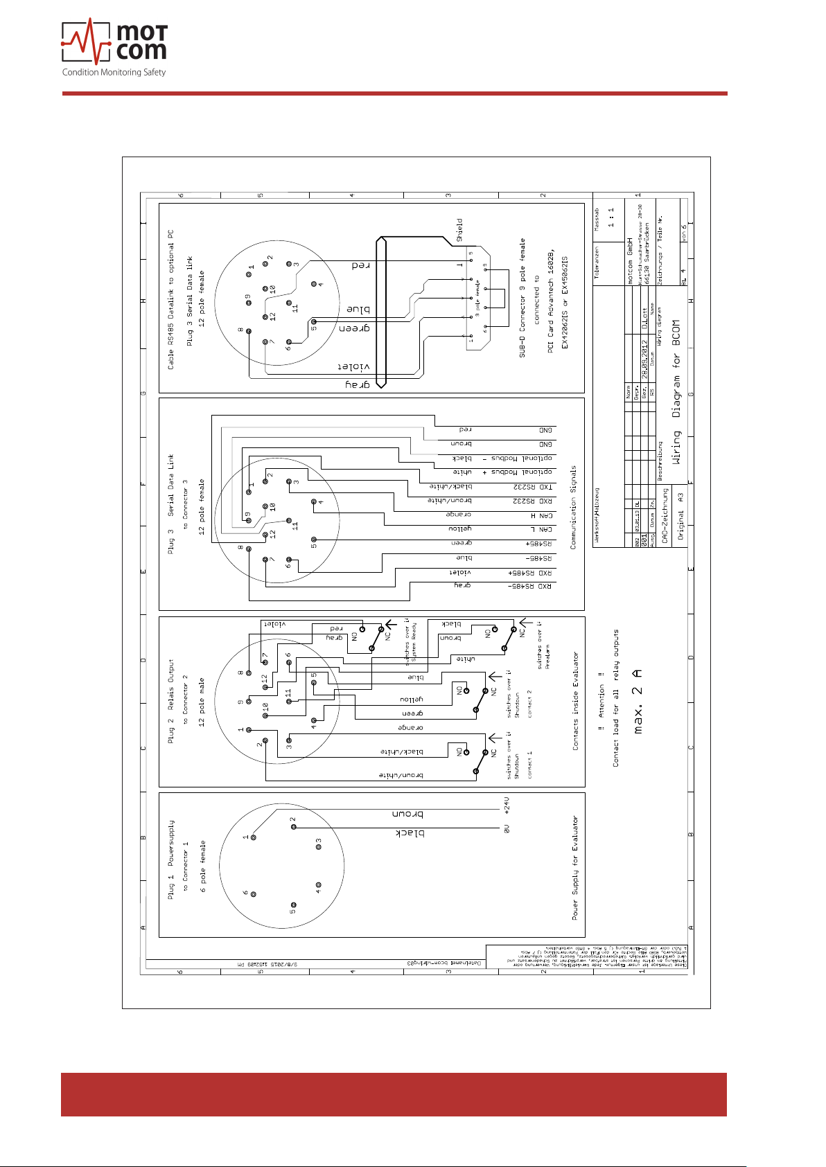
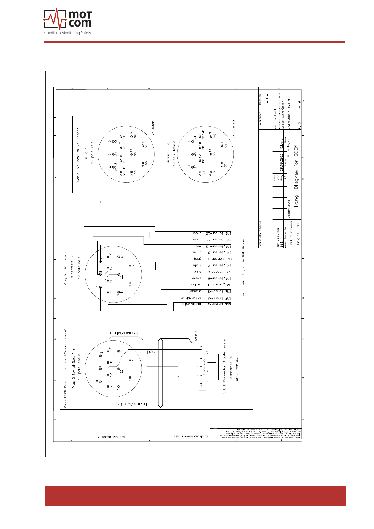
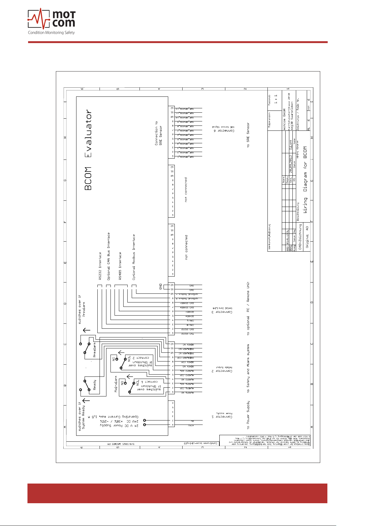
8.2. Wiring Diagrams .......................................................................................8.6
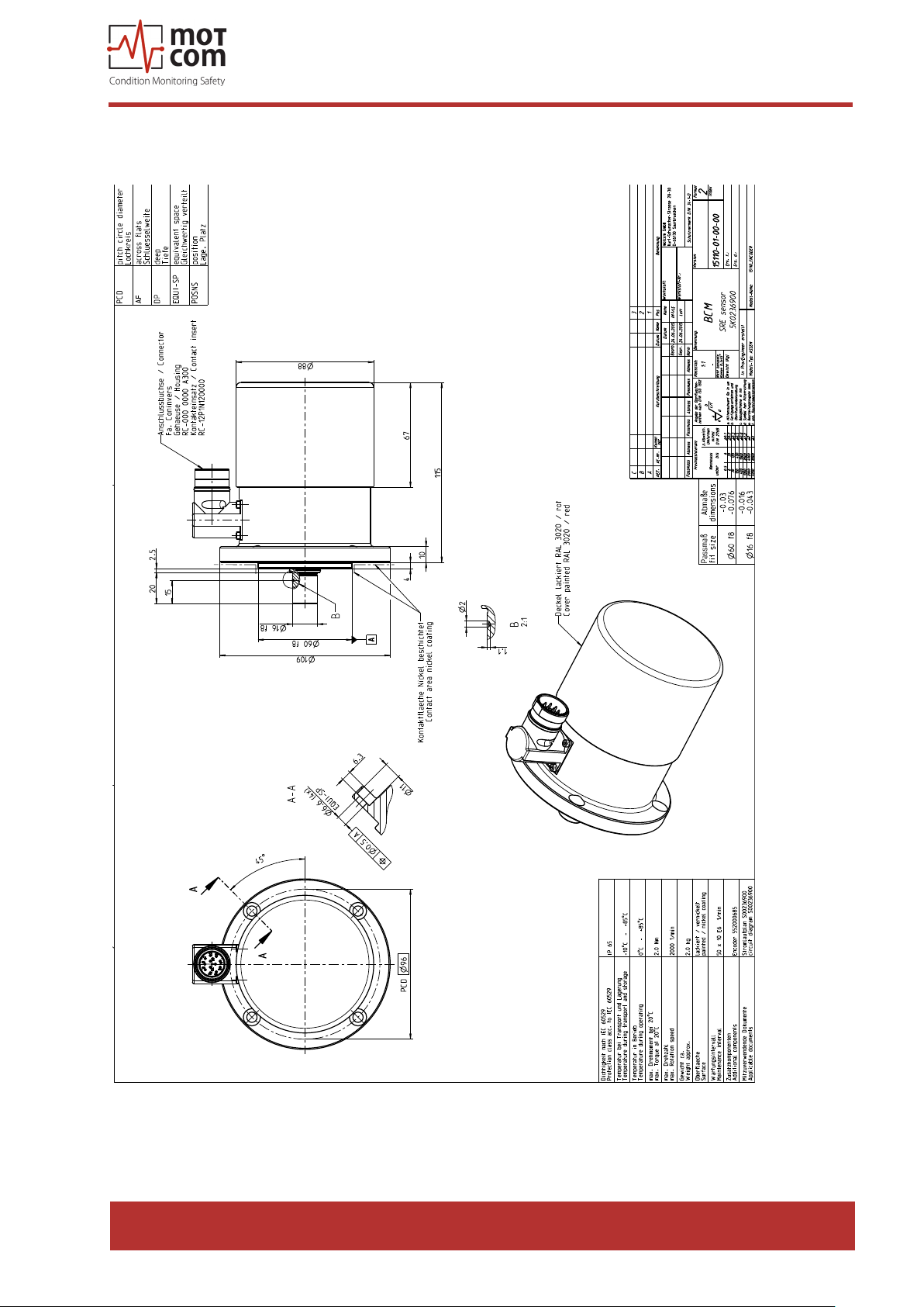
8.3 Drawings ................................................................................................8.11
Page viii
Release 130301 (revision 190211)
Page 9
motcom® BeCOMS® | BCom
User Manual
1. System Description
1.1. Components
1.1.1. BCom - Principle
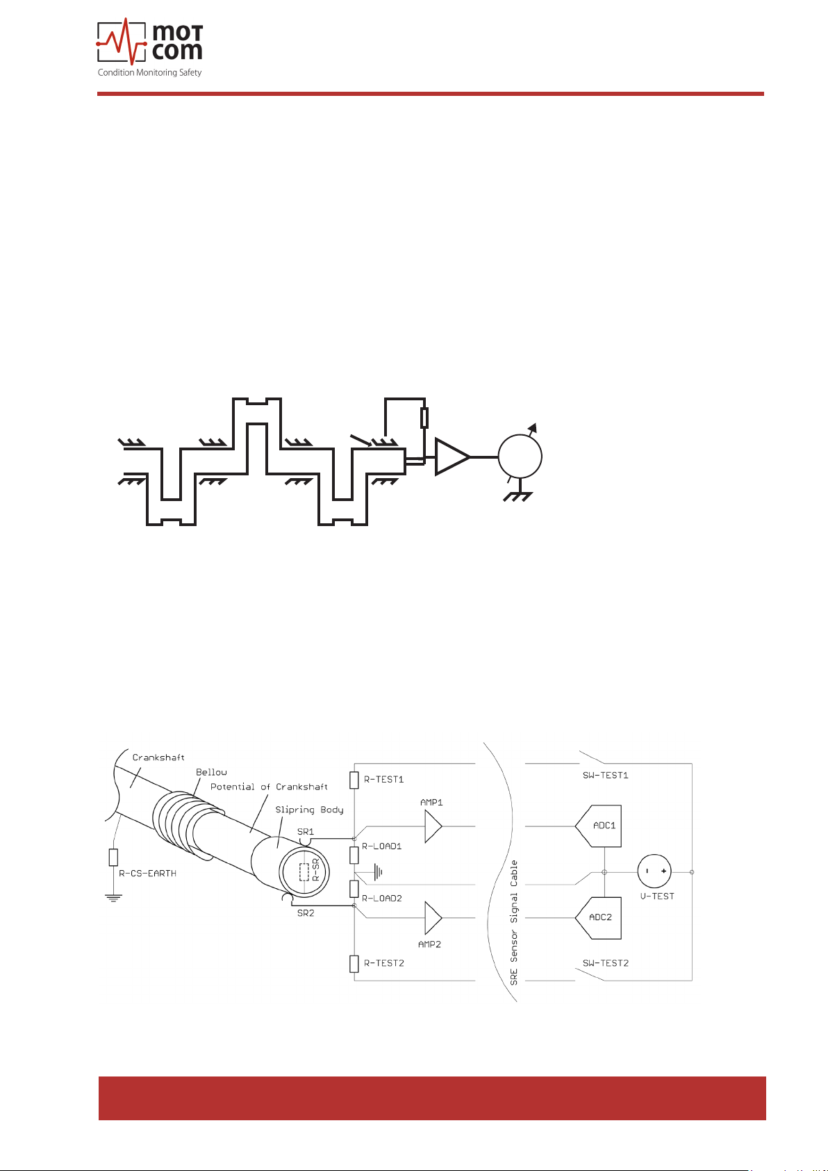
The BCom system can be used on engines and motors (turbines, pumps, etc.)
where the crankshaft is not electrically isolated from bearing shells. It utilises the
thermo-electrical (Seebeck) eect for monitoring the condition of the engine/motor,
bearings and slip surfaces, allowing to recognise failures at an early point, which
prevents large-scale part damages.
On diesel engines, the BCom system measures and evaluates thermal voltage
between the crankshaft and bearing shells, signalling changes that can be
interpreted as dangerous.
R
Dry friction
V
Fig. 1.1. Measurement principle in a diesel engine
This thermovoltage is very low (< 1 mV) during normal engine operation while the
lubrication oil acts as electrical isolation. If the oil lm between a rotating part and
its bearing becomes thinner and ruptures, which can be caused for example by
presence of metal particles in a bearing clearance, when the engine crankshaft
rubs against a bearing shell, the thermovoltage detected by SRE sensor rises.
Fig. 1.2. Redundant thermovoltage measurement
Release 130301 (revision 190211)
Page 1.1
Page 10
motcom® BeCOMS® | BCom
User Manual
The BCom system makes it possible to localise the beginning failure, because the
engine ring sequence is stored among other setting of BCom Evaluator. Parallel to
thermovoltage, BCom also monitors engine rotation speed and direction of rotation
with the help of an incremental encoder.
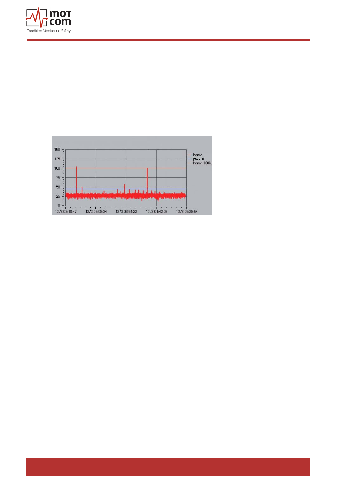
When a cylinder res, a higher thermo voltage signal is generated at spots aected
by dry friction due to high pressure. These voltage peaks superimposed with data
from the incremental encoder and with the ring sequence help to determine the
location where the oil lm ruptures.
Fig. 1.3. Thermovoltage signal at the Data_Indicator
This information proved to be essential in early-stage diagnostic for engine parts, thus,
the BCom system is an important and eective tool in reducing engine maintenance
costs.
The thermovoltage and engine rotation speed are displayed at the control device,
Evaluator, and could be optionally displayed remotely on a PC. Both devices will
graphically indicate dangerous changes in measured values, so that the engine
personnel can immediately make decisions on further engine load and on repair
steps. The BCom system can also be connected to custom alarm or control devices
which can automatically stop the engine, preventing further engine damages. Thus,
the engine repair eorts and costs are minimised, while early detected problems can
be in most cases eliminated together with common maintenance works.
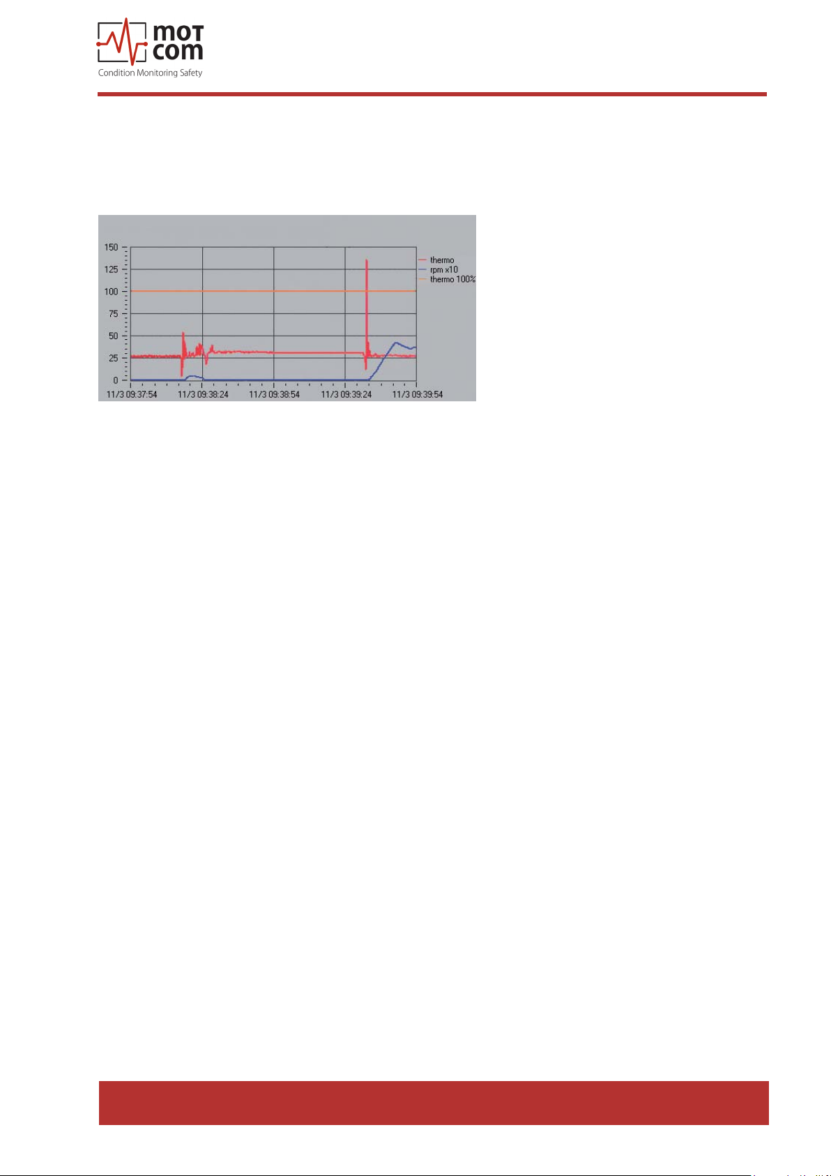
Thermovoltage peaks can be observed every time the engine starts, because the
oil lm is absent at this point and the crankshaft contacts the bearings. After a few
seconds the oil lm begins to build up and isolates crankshaft and bearing shells if
the engine is in a healthy condition.
Page 1.2
Release 130301 (revision 190211)
Page 11
motcom® BeCOMS® | BCom
User Manual
The thermovoltage value then sinks to a certain basic level that is specic to the
engine, and depends on its load and operating time. The BCom Evaluator monitors
all changes that occur during the engine operation and triggers an alarm should
these changes indicate danger.
Fig. 1.4. High thermovoltage signal at engine start-up
The eect of high voltage peaks also occurs when the engine is being shut down.
Some thermovoltage level can be measured even some time after engine stop,
until the temperatures at contact spots level out.
Release 130301 (revision 190211)
Page 1.3
Page 12
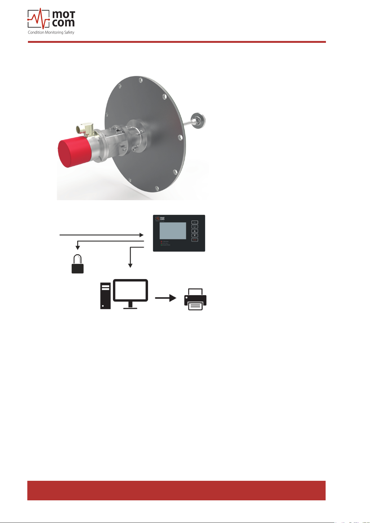
1.1.2. BCom System Overview
motcom® BeCOMS® | BCom
User Manual
SRE with mechanical Adapter Set
24V DC
BeCOMS | BCom Evaluator
Local Alarm System
PC with Logger software / optional printer
Fig. 1.5. System Overview
• One Slip Ring Encoder (SRE) installed on the housing on a free end
of the crankshaft. The rotating shaft of the SRE is mechanically attached to the free end of the crankshaft, usually with a vibration damper.
Page 1.4
• One BCom Evaluator as the Local Control Panel where the measured
values are displayed and the signal evaluation is performed. These values
can also be displayed on a computer in the engine control room via RS485
communication cable with the help of BCom Data_Logger software which
provides online visualization and storage of the signals transmitted by the
Evaluator. Furthermore, stored measurement data can be viewed and analysed
by Data_Indicator software and motcom Analysis software.
Release 130301 (revision 190211)
Page 13
motcom® BeCOMS® | BCom
User Manual
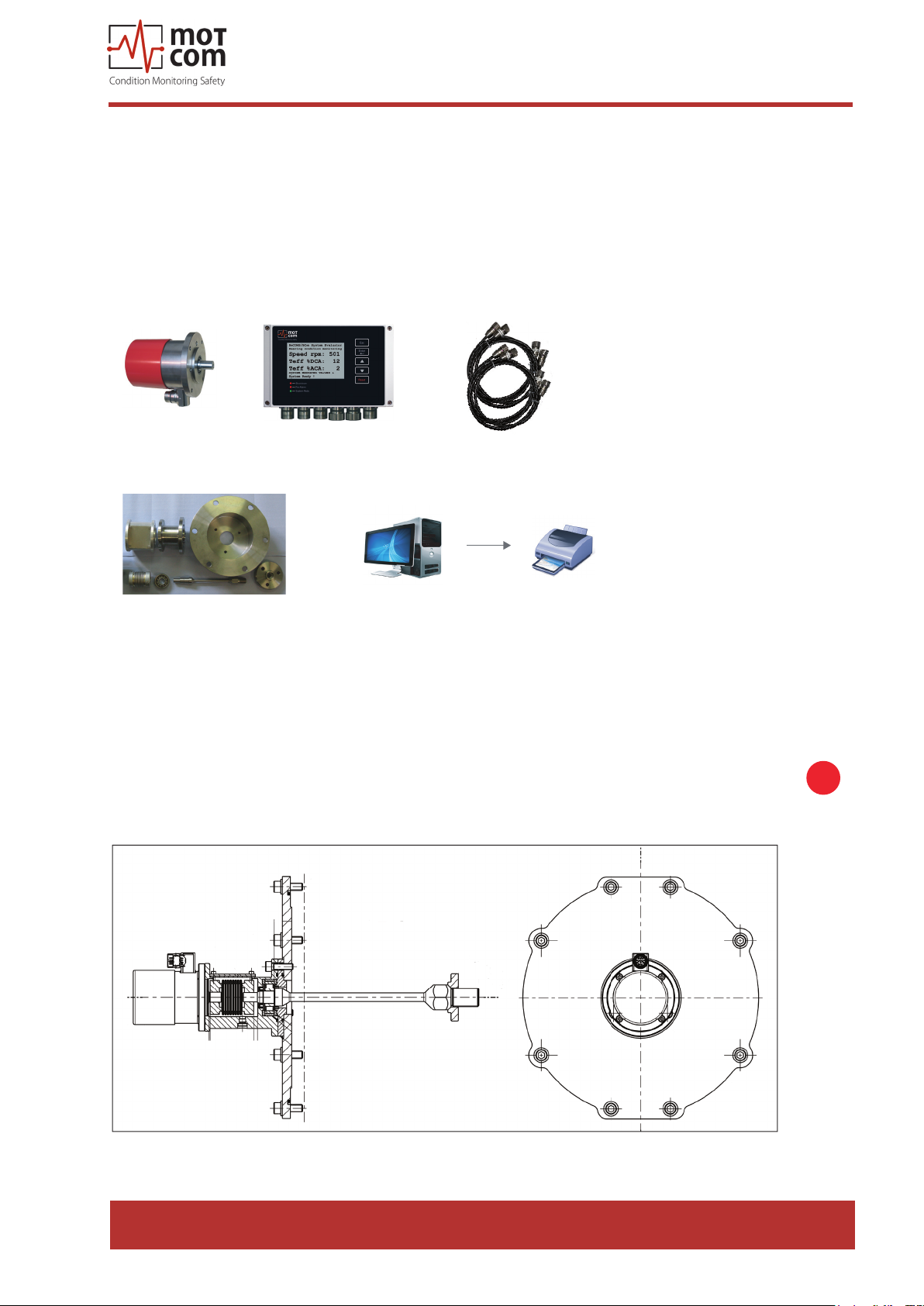
• One set of mechanical mounting/join adapters which includes shaft adapter
and cover, adapter housing with bearing, interface housing and cover.
• This manual; optionally, a backup CD with commissioning data.
• Optional PC with BCom Data_Logger software; a CD with Logger installation
and a soft copy of this manual.
SRE Slip Ring Encoder
Mechanical adapter specific to the engine
Fig. 1.6. Scope of delivery for BCom Professional system
BeCom Evaluator
cable set
optional PC with Logger software / printer
BCom installation and commissioning are performed by motcom GmbH personnel
or by its authorized partners. Installation procedure includes training for technical
sta at the engine site.
i
Fig. 1.7. Cut out model of a sample installation
Release 130301 (revision 190211)
Page 1.5
Page 14
1.1.3. BCom System Components
1.1.3.1 BCom Evaluator
motcom® BeCOMS® | BCom
User Manual
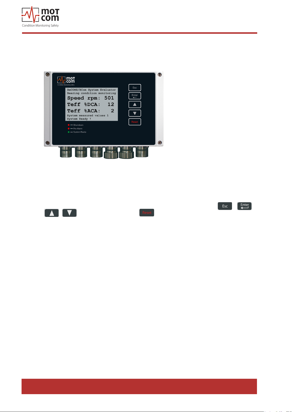
Fig. 1.8. BCom Evaluator
The Evaluator consists of a metallic case, a liquid crystal display (LCD), three
LEDs (Shut-down, Pre-Alarm, System Ready), four control keys ( , ,
, , ) and one reset button .
The electronics and the display of the BCom Evaluator are installed in a closed,
shock-proofed, water, dust and EMC resistant aluminium case, protection class
IP 66.
The Evaluator is provided for mounting close to the engine or in the engine control
room. The Evaluator operates reliably at temperatures between 0°C to 70°C and at
relative humidity up to 80%.
The installation of the Evaluator is performed via 2 assembly rigs. If required, the
Evaluator can be mounted vibration-free. In each case you have to pay attention
that the connection cable is passed loose in a loop and without traction to the plugin connections.
Page 1.6
The Evaluator is able to display the measurement values and BCom parameter
values on its LC-Display. It also provides some test procedures that can be
performed for BCom diagnostics.
Release 130301 (revision 190211)
Page 15

motcom® BeCOMS® | BCom
!
User Manual
The control keys of the Evaluator are made as lm-press buttons. During operation,
please be careful and do not press them with spiky or sharp items, instruments like
knifes, screw-drivers or ball-pens. Just touch the buttons with a slight pressure by
a ngertip.
If needed, the keypad can be wiped with a mild cleaning agent. Please never use
a solvent!
After successful installation and testing by service technicians approved by motcom
GmbH, the settings of the Evaluator should not be changed. The Evaluator does
not require regular maintenance.
Note: Firmware updates for the Evaluator will be available and may be applied to
your system only by service technicians approved by motcom GmbH.
Firmware updates are free of charge. Please contact motcom GmbH or an
authorized representative for details and further information.
i
Release 130301 (revision 190211)
Page 1.7
Page 16
motcom® BeCOMS® | BCom
User Manual
Page 1.8
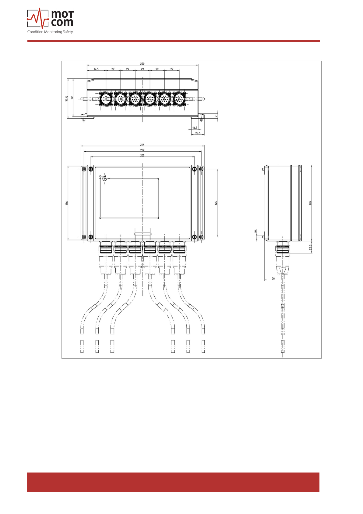
Fig. 1.9. Evaluator dimensions
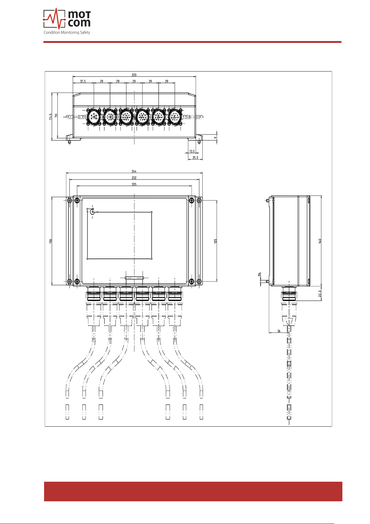
For the exact dimensions, please see under 8.3 Drawings
Release 130301 (revision 190211)
Page 17
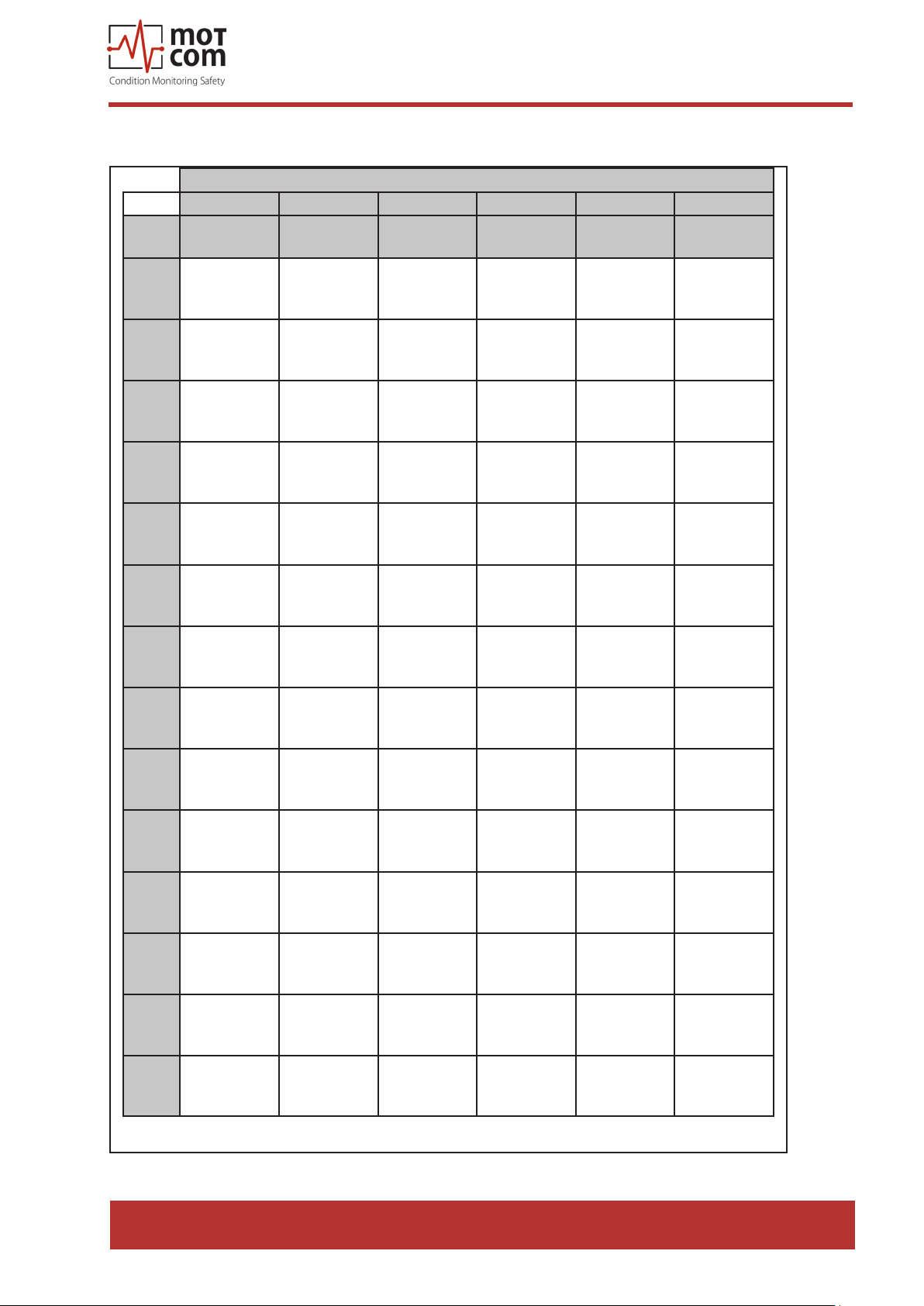
1.1.3.2. Connectors and pin-out of the BCom Evaluator
Connection at the Connectors of the Evaluator
1 2 3 4 5 6
Pin
Power
Supply
Relays
Serial Data
Link
Reserved Reserved SRE
motcom® BeCOMS® | BCom
User Manual
1
2
+24V
(brown)
0V
(black)
3
4
5
6
7
8
1st Alarm
Relay NO
1st Alarm
Relay COM
1st Alarm
Relay NC
2nd Alarm
Relay NO
2nd Alarm
Relay COM
2nd Alarm
Relay NC
Ready
Relay NO
Ready
Relay COM
TxD / 232 SRE-1
RxD / 232 SRE-2
CAN-H SRE-3
CAN-L SRE-4
RS485 + SRE-5
RS485 - SRE-6
RxD +
RS485
RxD -
RS485
SRE-7
SRE-8
9
10
11
12
Cable
Part.
No.
2xAWG 20
92000200000
Pre Alarm
Relay COM
Pre Alarm
Relay NC
Pre Alarm
Relay NO
Pre Alarm
Relay NC
12xAWG 20
92001200000
GND SRE-9
GND SRE-10
GND SRE-11
GND SRE-12
12xAWG 20
92001200000
Con-
nector
93000610000 93001220000 93001210000 93001220000
Set
(for further information like wire colors, please refer to pages 8.6 - 8.10)
Table 1.1. Connections of Evaluator
12xAWG 20
92001200000
Release 130301 (revision 190211)
Page 1.9
Page 18
1.1.3.3. Slip Ring Encoder (SRE)
motcom® BeCOMS® | BCom
User Manual
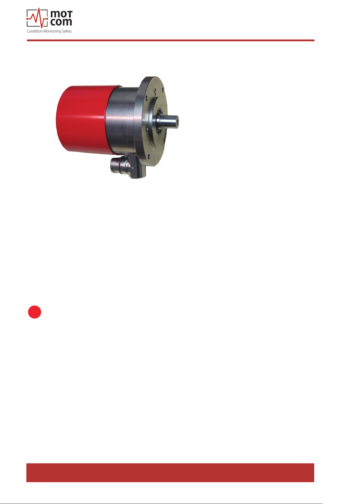
Fig. 1.10. SRE
The Connector-Set for the socket at the SRE: Art. No. 93001210000 has the wiring
assignment as listed on Table 1.1.on page 1.9 for the Connector-Set with the Art.
No. 93001220000
The Slip Ring Encoder is shaped as a cylinder. It is xed to a mounting board with
a ange and 4 cylinder-head screws. The SRE is identical for all engines. In each
individual case the mounting ange and the transmission shaft to the crankshaft of
the engine are adapted individually for each engine type. If necessary, SRE can be
dismounted for maintenance.
Info: The shaft and the mounting ange are determined, designed and manufactured
i
by motcom GmbH or by its authorized partners for each engine type. Only
in this case correct operation and trouble-free transmission of measurement
signals are guaranteed.
The Slip Ring Encoder contains a special slip ring with redundant carbon brushes
which receives the thermo-voltage signal from the crankshaft-engine system, and
an incremental encoder for measuring speed and rotating direction.
Page 1.10
The SRE is designed to work in typical environment conditions of diesel engines.
Please also refer to the technical data on page 1.11.
Release 130301 (revision 190211)
Page 19

motcom® BeCOMS® | BCom
1.1.3.4. Technical Data of BCom Slip Ring Encoder and Evaluator
Power Supply: 24V DC +30/-25%
Operating Current:
max. 1.5 A
Sensitivity: Adjustable in 5 steps
Relay-Outputs: Contact load for all relays:
max. 60V AC, 1A, 60VA / max. 60V DC, 1A, 60W
Alarm 1:
1 relay with 2 ground-free switch-over contacts, usually
congured as main alarm.
Wire break protection with 33 kOhm resistors (standard)
Alarm 2:
1 relay with 1 ground-free switch-over contact, usually
congured as pre alarm
Ready:
1 relay with 1 ground-free switch-over contact, energized
if system is fault-free
Interface: Serial Interface:
• RS485 for standardized industrial, bidirectional
communication
Communication Protocol:
• Modbus
• CAN Bus (optional)
User interface: LCD Display 240*128 dots
1 LED red “Shut-down”
1 LED red “Pre-Alarm”
1 LED green “System Ready”
Connection cable: for example:
• Scherer Kabel GmbH 12 AWG 20C UL
• Metrofunk 12 AWG 20C UL
• Huber + Suhner Radox MFHS-EMC
Environment
Conditions:
Ambient temperature in service:
0°C - 70°C for BCom Evaluator
0°C - 85°C for SRE
Ambient temperature in storage:
-25°C - 85°C
Protection:
IP65
User Manual
(GL-environment category D, EMC 2)
Release 130301 (revision 190211)
Page 1.11
Page 20
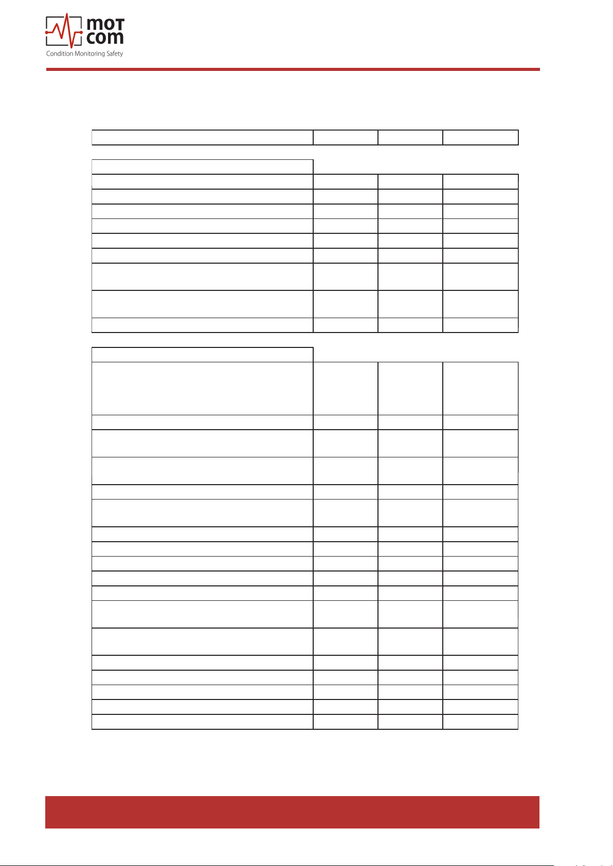
1.1.4. Editions of BCom System
Features Professional Advanced Basic
motcom® BeCOMS® | BCom
User Manual
Hardware
Power Supply 24V DC +30/-25% x x x
Sensitivity adjustable in 5 Steps x x x
2 alarm relays, Function programmable x x x
1 ready relay x x x
RS485 Interface x x x *
LC-Display 240x128 dots x x x
System status LEDs
(System Ready, Prealarm, Shutdown)
PC for data-logging which supports up to 6
systems
Modbus Interface o o o
Software Capabilities of the Evaluator
Setup of BeCOMS / BCom system
via the user-interface of the Evaluator or
via RS485 (text based setup using a terminal
program)
Displays Thermosignal in % alarm level x x x
Displays Thermosignal AC eective in % alarm
level
Displays Thermosignal DC eective in % alarm
level
Displays Thermosignal in mV x x x
Triggers (Pre)Alarm using AC and DC thermo
signal
Auto-check of SRE sensor by Evaluator x x x
Error Monitoring on Display x x x
AC and DC alarmlevels separately adjustable x x x
Displays engine speed in RPM x x x
Triggers overspeed alarm x x x
Dierent AC alarmlevels for 2 adjustable RPM
levels
Shows measured values in a graphic overview
display
Recording of data for Damage Localization x - Recording data of combustion cycle performance x - Data-output via RS485 x x x
Data-output via RS485 for combustion cycle x - Data-output via RS485 for Damage Localization x - -
x = included o = optional - =
x x x
x x -
x = included o = optional - =
x x x
x x x
x x x
x x x
x x x
x x x
not included
not included
Page 1.12
Table 1.2. Features
* only Setup function for Evaluator, no transmission of measured values
Release 130301 (revision 190211)
Page 21
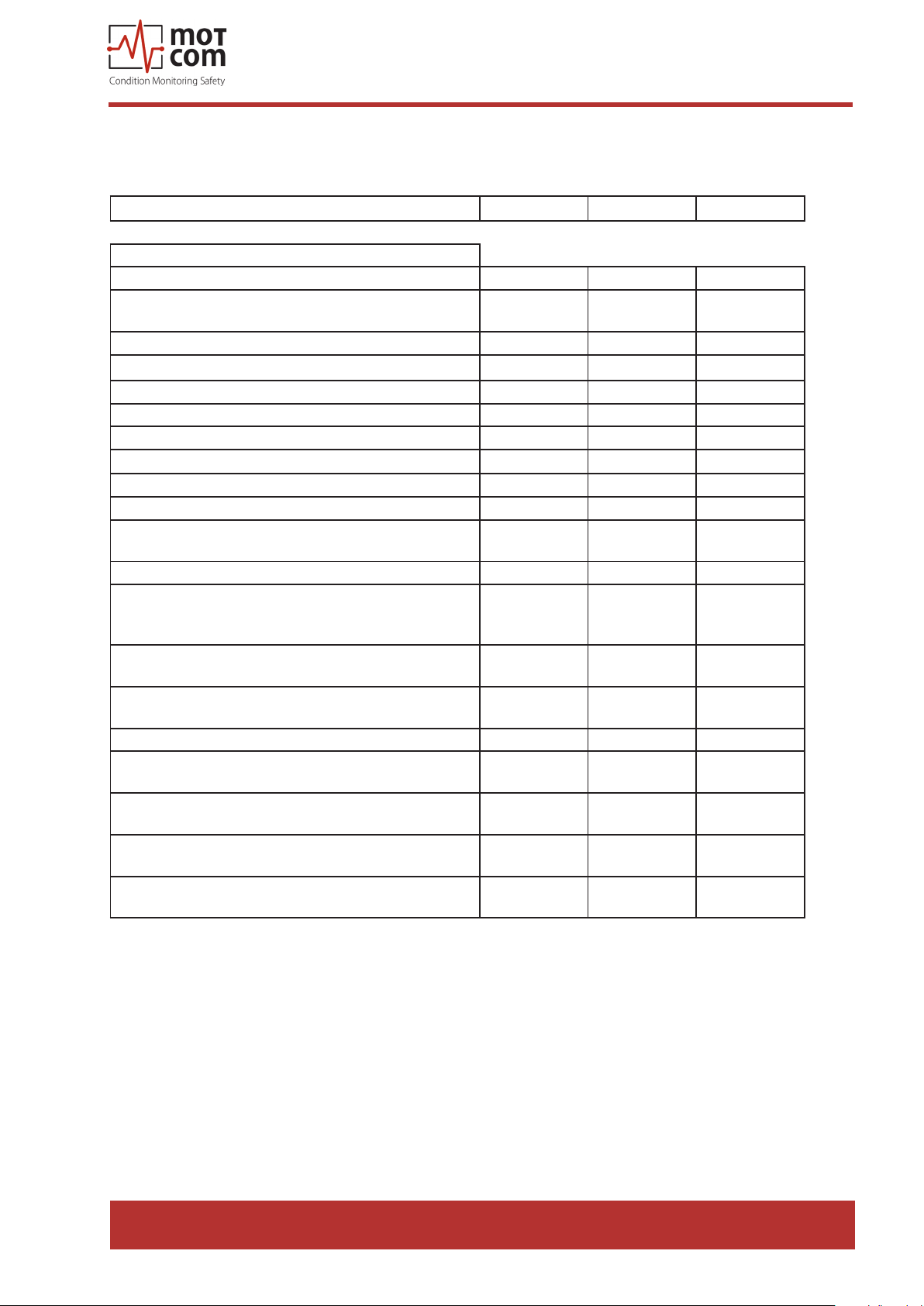
1.1.5. Versions of BCom System
Features Professional Advanced Basic
motcom® BeCOMS® | BCom
User Manual
Software PC (Logger, Data_Display)
Required Software shipped with system x x -
Logger version for 2, 4 or 6 BeCOMS / BCom systems
included
Displays Relais Status x x -
Displays Thermosignal in % and mV x x -
Displays Thermosignal AC e. in % alarm level x x -
Displays Thermosignal AC e. in % alarm level x x -
Displays engine speed in RPM x x -
Displays adjusted DC and AC alarmlevel x x -
Status window with plain text information x x -
Displays setup parameters x x -
Displays thermosignal (% and mV), thermosignal eective
and engine speed in one y-t graph
Minimized polar diagram in the main window x - -
Enlarged polar diagram in an own window,
incl. integrated engine-geometry
for damage localization
Cylinder Speed Dierence Diagram
for Evaluation of each single Cylinder
Cylinder Thermosignal Dierence Diagram
for Evaluation of Cylinder Signal
Storing Standard Data in Daily or Hourly Log File x x -
Storing Enhanced Data for Damage Localization
in Daily or Hourly Log File
Display Standard Data of Log Files by
Data_Indicator software
Display Enhanced Data of Log Files for Damage
Localization by Data_Indicator software
Possibility to analyse the Log Files with optional motcom
analysis Software
x = included o = optional - =
x x -
x x -
x - -
x - -
x - -
x - -
x x -
x - -
x x -
not included
Table 1.3. Versions
Release 130301 (revision 190211)
Page 1.13
Page 22
motcom® BeCOMS® | BCom
1.1.6. Intended Purpose of the Data_Logger Software (opt.)
User Manual
Attention:
This chapter only applies if you are running a BCom Advanced or
BCom Professional system! Otherwise, the following information
can be ignored.
The BCom
Data_Logger
Software
handles up
to six BCom
systems
The intension of the BCom Data_Logger Software is:
• to allow the measurements of a BCom to be monitored by means
of a computer
• to store the recorded data in daily/hourly log-les
• to display measured signals to allow trained engine operator to
localize the damaged part(s)
The BCom
Data_ Logger
!
software does
not replace
functions
of the safety
system
The Data_Logger Software does not replace the interconnection of
the BCom Evaluator with the engine safety and alarm system
The use of a computer with the BCom is only permitted when it is installed and
congured by motcom GmbH or by its authorized representatives.
motcom GmbH can only provide technical support if motcom GmbH approved
equipment, i.e. interface converter, plugs, etc., is used.
This manual should be shown to the operator how to make the best use of the
software and to alert of safety issues that may arise. The purpose of this manual
i
is to instruct the operator how to make the best use of the software and to alert of
safety issues that may arise.
All products mentioned in this manual are to be handled only by
personnel with appropriate electrical and computer knowledge, such
To be handled
only by
appropriately
trained
personnel
as international ISO standards and Microsoft Windows Operating
systems.
Any damages, either human or material, caused by the use of
the products described in this manual for any purpose other than
that intended, is solely the responsibility of the user and not of the
manufacturer.
Page 1.14
Release 130301 (revision 190211)
Page 23

motcom® BeCOMS® | BCom
User Manual
2. Installation
2.1. General
Installation and commissioning of BCom is conducted or supervised by personnel
from motcom GmbH or its authorized representatives.
The installation procedure includes training for the site operation personnel. The
commissioning data will be stored on the backup CD for later reference.
The wiring diagram and schematic given here are guidelines only. The actual wiring
will be adapted to the existing alarm and monitoring system on site.
Release 130301 (revision 190211)
Page 2.1
Page 24
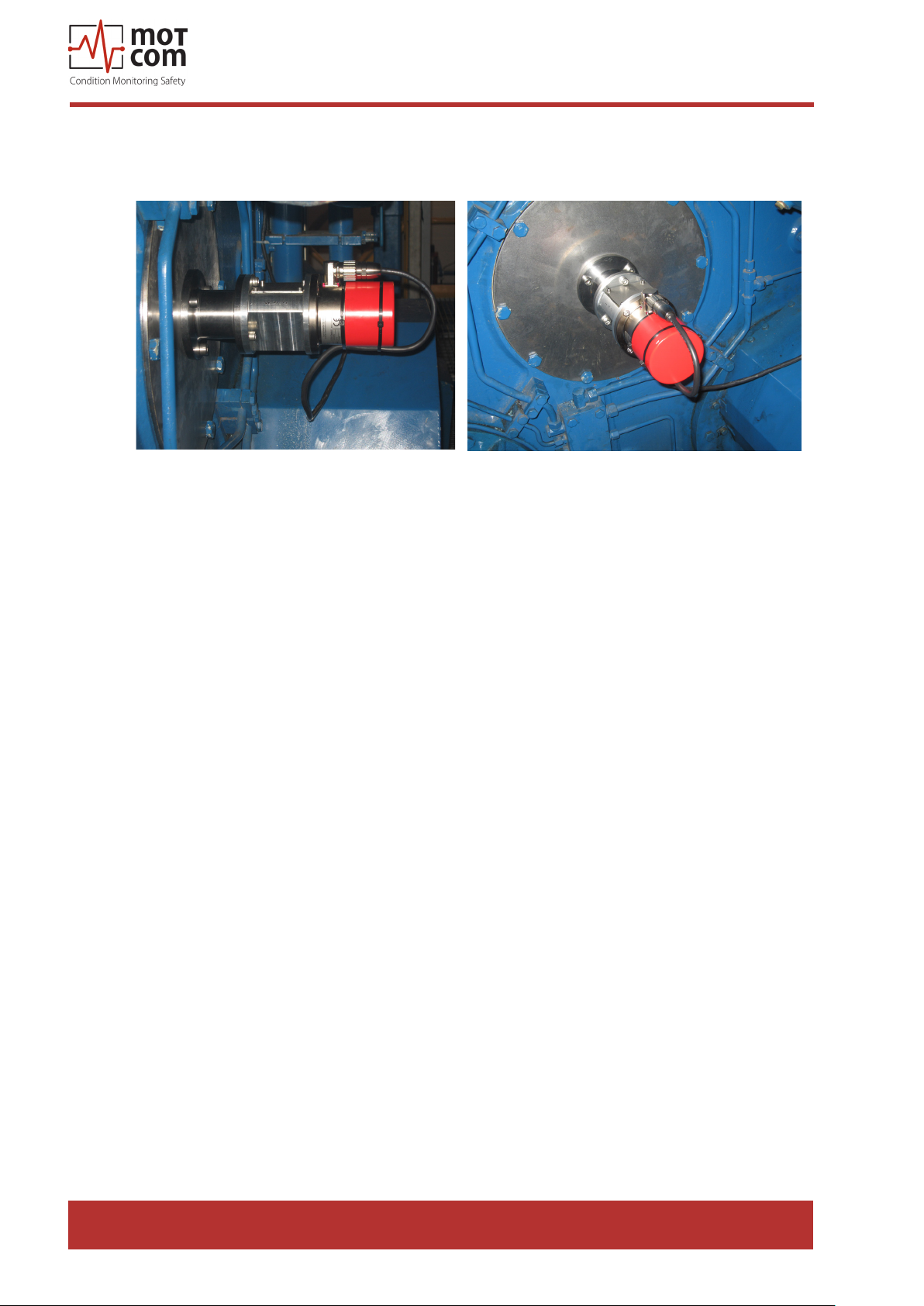
2.2. Installation Position
Fig. 2.1. Installation position
motcom® BeCOMS® | BCom
User Manual
The BCom Slip Ring Encoder is installed at the end of the crankshaft of the
combustion engine. The evaluator can be installed in the engine room near the
engine or, alternatively, in the engine control room. The length of signal cables
should not exceed 100 m.
Page 2.2
Release 130301 (revision 190211)
Page 25
motcom® BeCOMS® | BCom
User Manual
2.3. SRE Mechanical Adjustments
The Slip Ring Encoder is centered during installation, and it is not necessary to do
it afterwards. Replacing the SRE can be performed without re-centering.
During the BCom installation the SRE has to be synchronized with the engine’s
crankshaft. This has to be done only once!
This involves positioning the engine at the ring TDC (see chapter 3.2.) at No. 1
cylinder and nding incremental encoder impulse oset (at four-stroke engine Inlet
and Outlet valves are closed).
The BCom SRE may only be replaced by personnel of motcom GmbH or by its
authorized representatives.
!
Release 130301 (revision 190211)
Page 2.3
Page 26
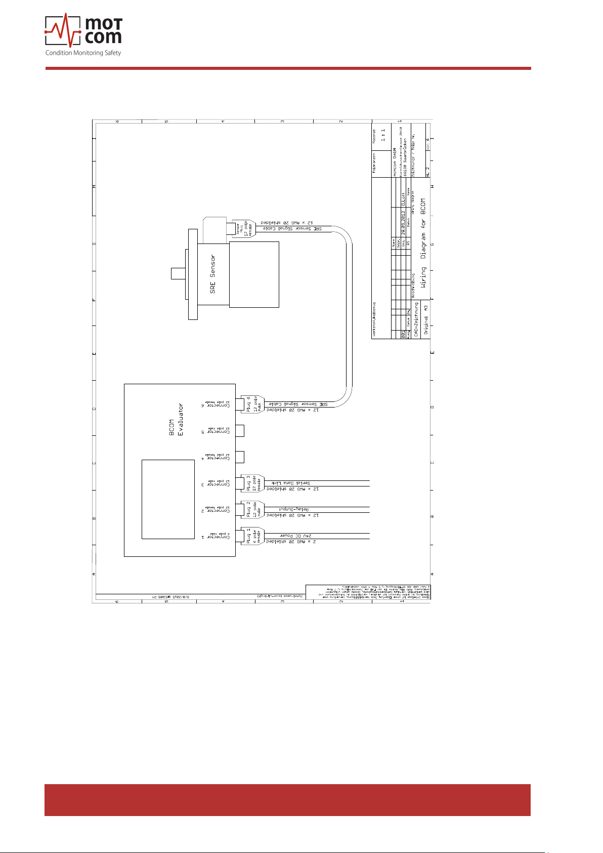
2.4. Wiring Diagram
motcom® BeCOMS® | BCom
User Manual
Page 2.4
Fig. 2.2. Principle connection
The cable types for power supply, relay output, data link and connection of the SRE
sensor are shown in Fig. 2.2. Principle Connections.
For connector details please refer to chapters 1.1.3.2. on page 1.9 and 8.2 on page
8.6.
Release 130301 (revision 190211)
Page 27

motcom® BeCOMS® | BCom
User Manual
2.5. Software Installation (optional)
Attention: This chapter only applies if you are running a BCom Advanced or
BCom Professional system! Otherwise, the following information can
be ignored.
The BCom Data_Logger and Data _Indicator software is pre-installed on the
hard disk of the supplied computer. The programmes must be congured correctly
according to the system specic conguration on site after BCom commissioning.
Please refer to BCom Data_Logger and Data_Indicator manual for information.
Upon request, a backup CD with
1) a softcopy of this manual
2) the BCom Data_Logger and Data_Indicator setup programs
3) the commissioning data
can be shipped by motcom GmbH.
!
Note:
BCom Data_Logger and Data_Indicator installation steps are not described in this
manual to avoid any unauthorized attempt to reinstall it. If necessary, please contact
motcom GmbH or its authorized representatives for further information.
i
Release 130301 (revision 190211)
Page 2.5
Page 28

motcom® BeCOMS® | BCom
User Manual
2.6. PC Requirements (optional)
Attention: This chapter only applies if you are running a BCom Advanced or
!
The monitoring computer should have the following minimum requirements:
• Intel I5 processor 2.66 GHz or higher
• CD-Rom drive, recommended CD-R/W drive
• min. 4GB DDR3 RAM **
• Hard Disk with a capacity of min. 500 GB for recording data (approx. 100MB per
day per BCom set) **
• supports Windows 7, 8.1 and 10
• mouse, keyboard
• at least 3 PCI slots **,
• Display resolution 1280 x 1024 or higher **
BCom Professional system! Otherwise, the following information can
be ignored.
**) depending on how many BCom-applications running parallel on the same PC
As a personal computer is usually not equipped with a RS485 interface, motcom
GmbH provides optionally either the necessary converter, incl. power supply
equipment, to convert the RS485 signal of the BCom Evaluator into the required
RS232 PC-signal (see Fig. 7.12 and Fig 7.13, page 7.5) or a PCI card installed in
the computer (see Fig. 7.14 and Fig. 7.15, page 7.6).
The RS485 cable length must not exceed 400 m.
Page 2.6
Release 130301 (revision 190211)
Page 29
motcom® BeCOMS® | BCom
3. Commissioning
3.1. Pre-Commissioning Checks
Check for the following:
1. correct wiring as given in chapter 1.1.3.2 and chapter 2.4.
2. correct power supply on BCom Evaluator
3. BCom Evaluator display is on
4a. correct power supply on RS-485 converter
5a. green power light on
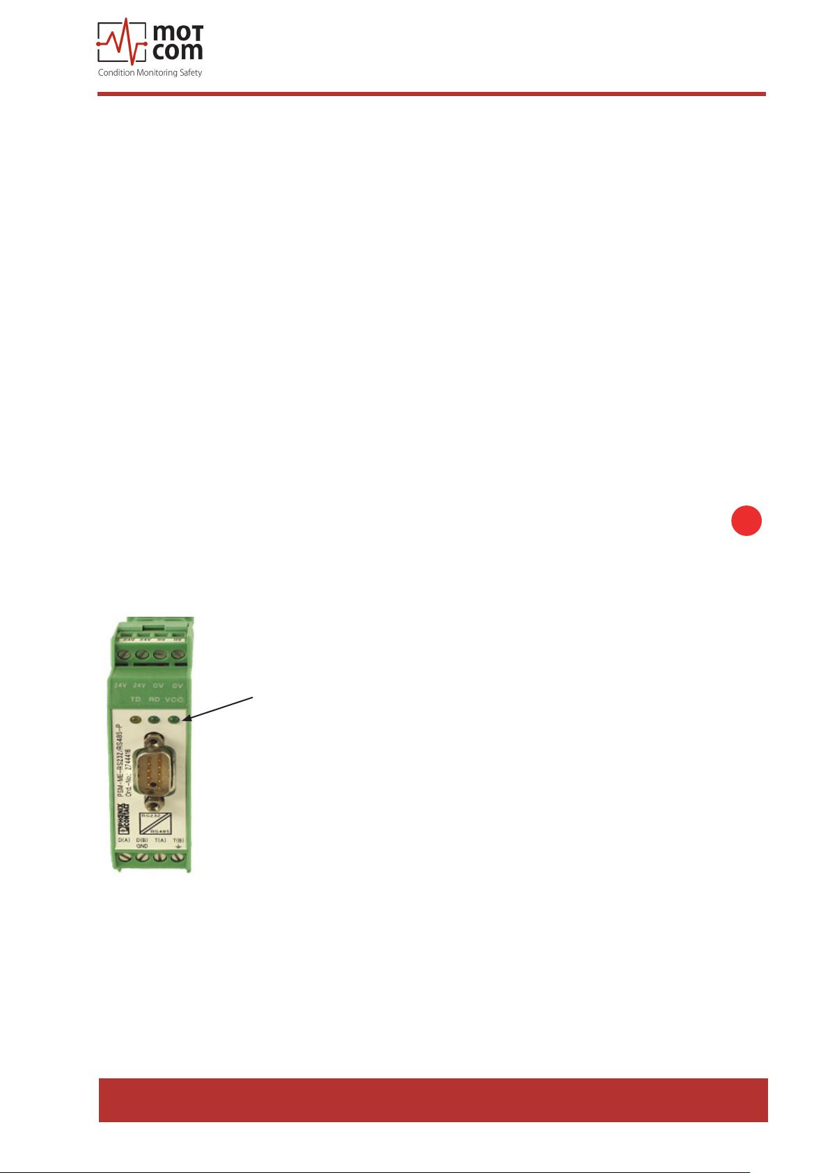
6a. the RS-485 converter rate setting is correct
4b. PCI card is built into the PC correctly
5b. PCI card driver for the corresponding OS is correctly installed
User Manual
7. COM-Port of the computer is correctly assigned
Note: Steps 4a – 6a are required if a RS-485 converter is used; steps 4b – 5b are
for the case when a PCI card is built into the PC.
LED indicating
power supply
i
Fig. 3.1. RS-485 converter, LED indicating power supply
Release 130301 (revision 190211)
Page 3.1
Page 30
motcom® BeCOMS® | BCom
!
User Manual
3.2. Syncronization of the BCom Sensor with the ring TDC of
the rst cylinder
At the installation of BCom sensor a one time calibration of the incremental
encoder has to be performed. This involves synchronising the neutral point of the
incremental encoder with the ring Top Dead Center (TDC) of cylinder 1 by nding
oset between them.
It is important that the ring TDC is chosen at four-stroke engines, that is, when inlet
and outlet valves are closed.
The following procedure may only be executed by authorized personnel:
• Turn engine to ring TDC of rst cylinder (number 1 at inline engine, A1 at
v-type engine), all valves must be closed!
• Go to chapter 3.6.5.1.10. IS Impuls Oset (page 3.12) at the Evaluator
menu
• Start Impuls Oset detection in the Evaluator menu
• Turn engine in normal rotation direction until Impuls Oset detection is
nished
• Leaving 3.6.5.1.10. IS Impuls Oset (page 3.12), the oset will be stored in
the Evaluator’s EEPROM
• Restart evaluator
• The syncronization procedure is done
Attention: Syncronization must be repeated after all works that required the
mechanical connection between crankshaft and SRE sensor to be
opened!
Page 3.2
Release 130301 (revision 190211)
Page 31

motcom® BeCOMS® | BCom
User Manual
3.3. Data Sampling
As soon as BCom Evaluator is powered up, it starts the initial self check procedure
and shows the READY status if all pre-set conditions are fullled. This self check
procedure is carried out in a certain cycle.
Regardless of the GREEN READY LED status of the BCom Evaluator, if a working
BCom Slip Ring Encoder is connected to it, the BCom Evaluator samples the signals
from the BCom SRE at a certain sampling rate. After that, the Evaluator converts
them into digital signals, analyzes, evaluates and displays them on its LCD-display.
These data including detected events are continuously made available through the
RS485 interface to the installed PC with BCom Data_Logger software for remote
monitoring and further processing. It is also possible to set up some BCom Evaluator
parameters from the PC using standard Windows HyperTerminal application.
Depending on the conguration, the BCom Data_Logger software can manage up
to 6 BCom systems on a single computer. The measured values and events will
be monitored and displayed continuously on the computer, and stored in a distinct
directory on the hard disk for each connected BCom system.
Release 130301 (revision 190211)
Page 3.3
Page 32

motcom® BeCOMS® | BCom
User Manual
3.4. Alarm Setting and Triggering
There are 3 alarm relays integrated in the BCom Evaluator:
• 1st Alarm relay: always assigned to main alarm, aditionally programmable as pre-
alarm or over speed alarm
• 2nd Alarm relay: programmable as main alarm or pre-alarm or both and/or over-
speed alarm
• 1 Ready relay: indicates the system status
The BCom has a self check procedure which is carried out in a certain cycle. If any
one of the conditions for System Ready status is not detected the BCom Evaluator
switches o the GREEN READY LED and the Ready relay opens. Error code and
text error message are shown on the LCD display of the Evaluator and also in the
event window of BCom Data_Logger on the monitoring computer.
BCom enables to set dierent alarm sensitivity levels by dening dierent thermo
voltage signal thresholds as alarm condition. Thermo signal alarm levels are
encoded as numbers from 1 to 5 (the higher the number is the less sensitive is the
system).
Over-speed alarm level is given in RPM.
Alarm sensitivity levels must be set at the BCom Evaluator. If alarm conditions are
fullled, the rmware of the BCom Evaluator triggers the corresponding alarm.
The BCom monitoring software on the computer does only registering, recording,
displaying and storing data!
For example, the following set of conditions should be met in BCom in order to
trigger Main Alarm:
1) The GREEN READY LED has to be on.
2) The measured thermo voltage signals should be higher than the pre-set alarm
level over a certain period of time.
3) The increase of these measured signals over time should be higher than a certain
value.
4) The engine rotation speed should be higher than pre-set minimal value.
If BCom Evaluator triggers Main Alarm it does not mean that the aected parts have
been damaged irreparably.
Depending on the pre-set alarm level and on wiring to the engine site alarm
devices, Main Alarm alerts the operator that the tolerated level has been exceeded,
indicating that further investigation of BCom signals is needed, and may initiate an
engine shutdown.
Page 3.4
Release 130301 (revision 190211)
Page 33

motcom® BeCOMS® | BCom
User Manual
By selecting the appropriate sensitivity level, the operator denes up to which
extend he would allow moving parts to be aected by friction.
With this information of fault on early stage, the operator is aware of the progressing
problem and has enough time for making decisions on engine maintenance and
repair.
In case of an alarm triggering, it is shown
• by the LED indicators on the BCom Evaluator
• by the BCom Data_Logger software on the monitoring computer
• by alarm indicators of the engine alarm devices, depending on wiring
Release 130301 (revision 190211)
Page 3.5
Page 34
motcom® BeCOMS® | BCom
!
User Manual
3.4.1. Alarm Resetting
• In case of a Pre-Alarm triggered:
If the conditions for a Pre-alarm are not conrmed after pre-set time period, the
Pre-Alarm will be reset automatically by the system.
• In case of a Main-Alarm triggered:
The Main Alarm will not be reset automatically by the system even after the
conditions that led to it are not met any more. Main Alarm can only be reset
manually at the BCom Evaluator by pressing the RESET button for 3 seconds.
• In case if Over-speed Alarm triggered:
Over-speed Alarm is not being reset automatically by the system either! It must
be reset by pressing the RESET button at the Evaluator for 3 seconds
Attention: Main-Alarm cannot be reset through the Data_Logger software, but only
at the BCom Evaluator by pressing the RESET-Button for 3 seconds.
3.4.2. Error Resetting
• In case of a System Not Ready status:
Only if all conditions for System Ready status are re-established (e.g. the problem
indicated on the LC-Display of BCom Evaluator is xed by the operator), the
System Ready status will be reactivated automatically by the system.
Exceptional case: In case of a communication error, the Evaluator has to be
restarted to reactivate the System Ready status!
Page 3.6
Release 130301 (revision 190211)
Page 35
motcom® BeCOMS® | BCom
User Manual
3.5. Settings & Parameters / Using the Evaluator
3.5.1. Basic Usage of the Evaluator
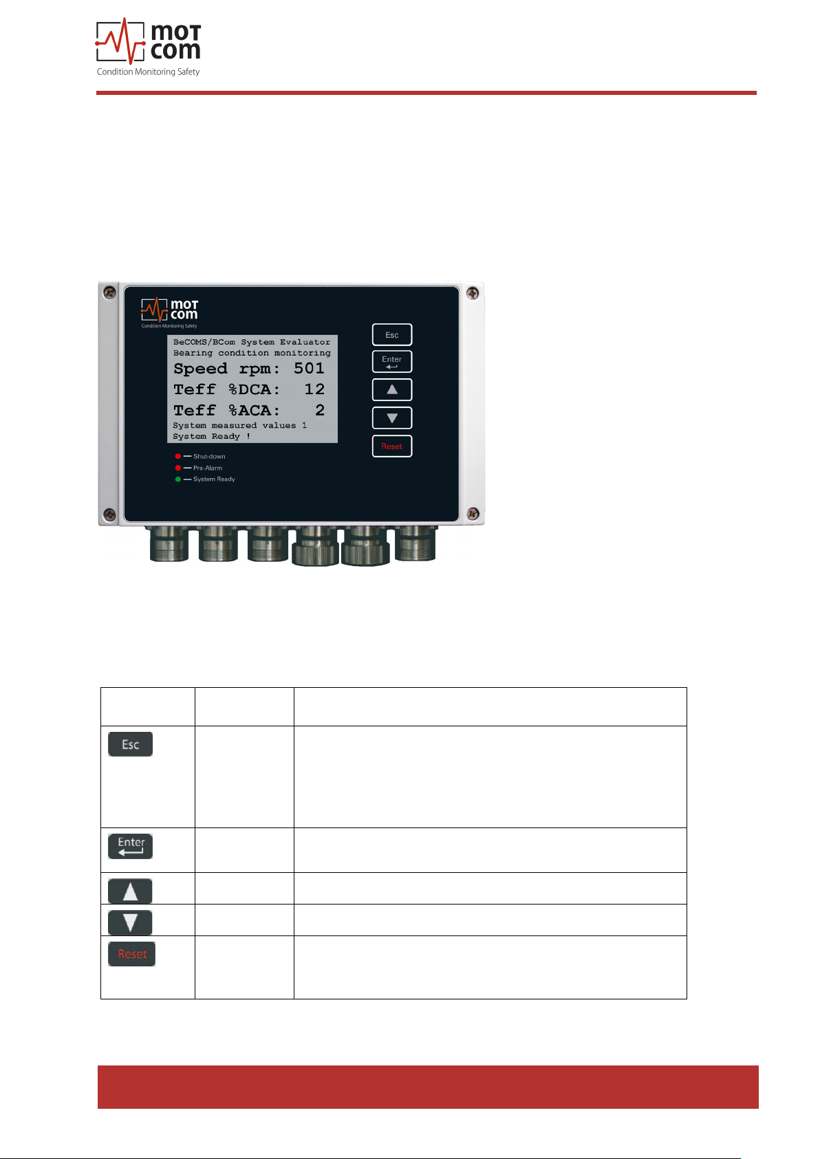
The Evaluator has an LC-display with the resolution 240x128, ve control buttons
and three LEDs that indicate the current system status.
As soon as the Evaluator is powered up, the initial info screens are shown for
several seconds, and then the display switches to default screen:
Fig. 3.2. BCom Evaluator default screen:current BCom measured values
The BCom system information and settings are organised in a tree-like menu. The
user can view the menu elements on the LC-display, move between them and
change some system settings using Evaluator buttons:
Evaluator
button
Symbol in
Button function
text
[Esc] go to the upper menu level, or cancel the change of
system value.
If [Esc] is pressed after entering the sublevel of
menu items “Setup Parameter” or “Setup CPU”, the
Evaluator will restart
[Enter] enter a sublevel, or confirm a selected system
value
[▲] move one menu item forward
[▼] move one menu item backward
[Reset] reset alarm status
If Evaluator indicates alarm, press the [Reset]
button and hold for 3 sec to reset the alarm status
Below is a description of BCom menu items and sublevels:
Release 130301 (revision 190211)
Page 3.7
Page 36
3.6. Menu structure
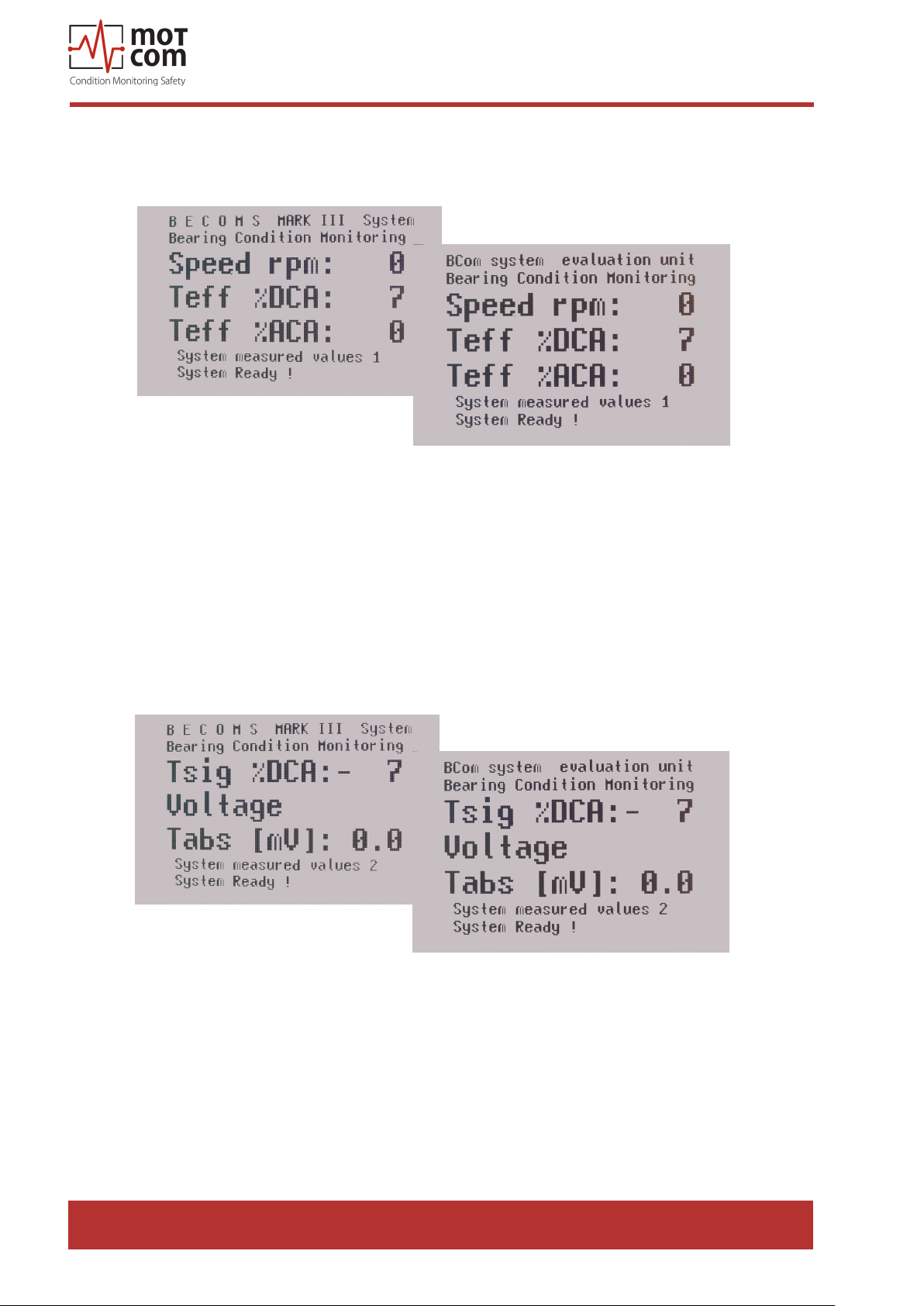
3.6.1. System measured values 1 (Default screen)
Fig. 3.3.BCom system measured values, default screen
motcom® BeCOMS® | BCom
User Manual
Shows the current BCom measured values for the connected SRE sensor:
Speed rpm: - engine rotation speed in RPM
Te %DCA: - eective value of thermovoltage in percents of DC alarm level
Te %ACA: - eective value of thermovoltage in percents of AC alarm level
3.6.2. System measured values 2
Page 3.8
Fig. 3.4. BCom system measured values, second screen
Shows further current BCom measured values for the connected SRE sensor:
Tsig %DCA: - thermovoltage in percents of DC alarm level
Voltage Tabs [mV] : - absolute thermovoltage in mV
Release 130301 (revision 190211)
Page 37
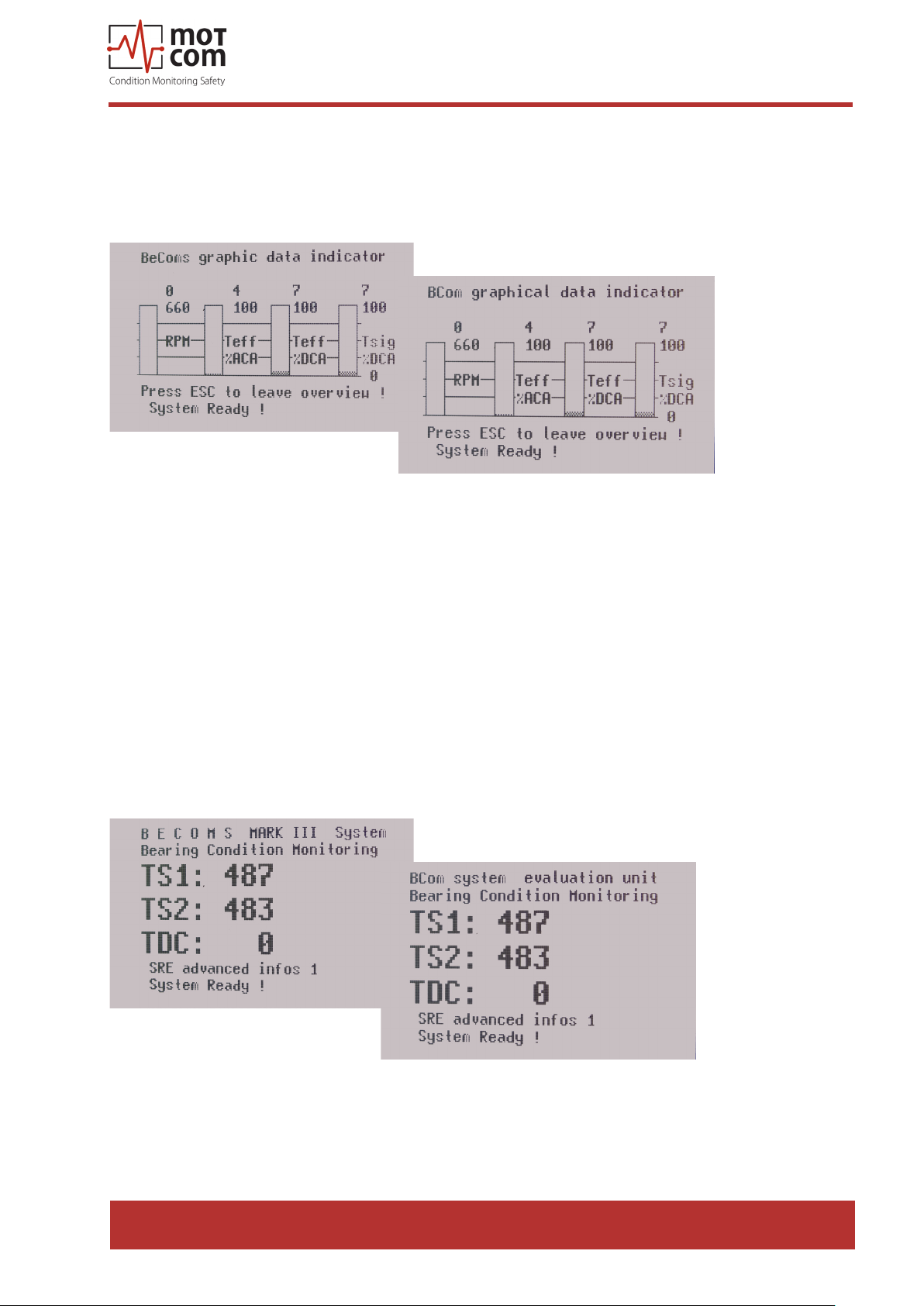
3.6.3 Graphic overview
Displays the current measured values as a bar diagram.
3.6.3.1. BCom graphical data indicator
motcom® BeCOMS® | BCom
User Manual
Fig. 3.5. BCom graphical data indicator
The displayed bars are:
RPM - engine rotation speed in RPM
Te %ACA - eective value of thermovoltage in percents of AC alarm level
Te %DCA - eective value of thermovoltage in percents of DC alarm level
Tsig %DCA - thermovoltage in percents of DC alarm level
3.6.4. SRE advanced infos
Displays advanced BCom system values.
3.6.4.1. SRE advanced infos 1
Fig. 3.6. SRE advanced infos 1
Release 130301 (revision 190211)
Page 3.9
Page 38
motcom® BeCOMS® | BCom
TS1: - the value at the analog/digital converter of the rst
thermovoltage measurement channel
TS2: - the value at the analog/digital converter of the second
t hermovoltage measurement channel
TDC: - the calculated indicator of TDC (Top Dead Center) of the
cylinder 1. If cylinder 1 is in TDC, the value is 1,
otherwise 0.
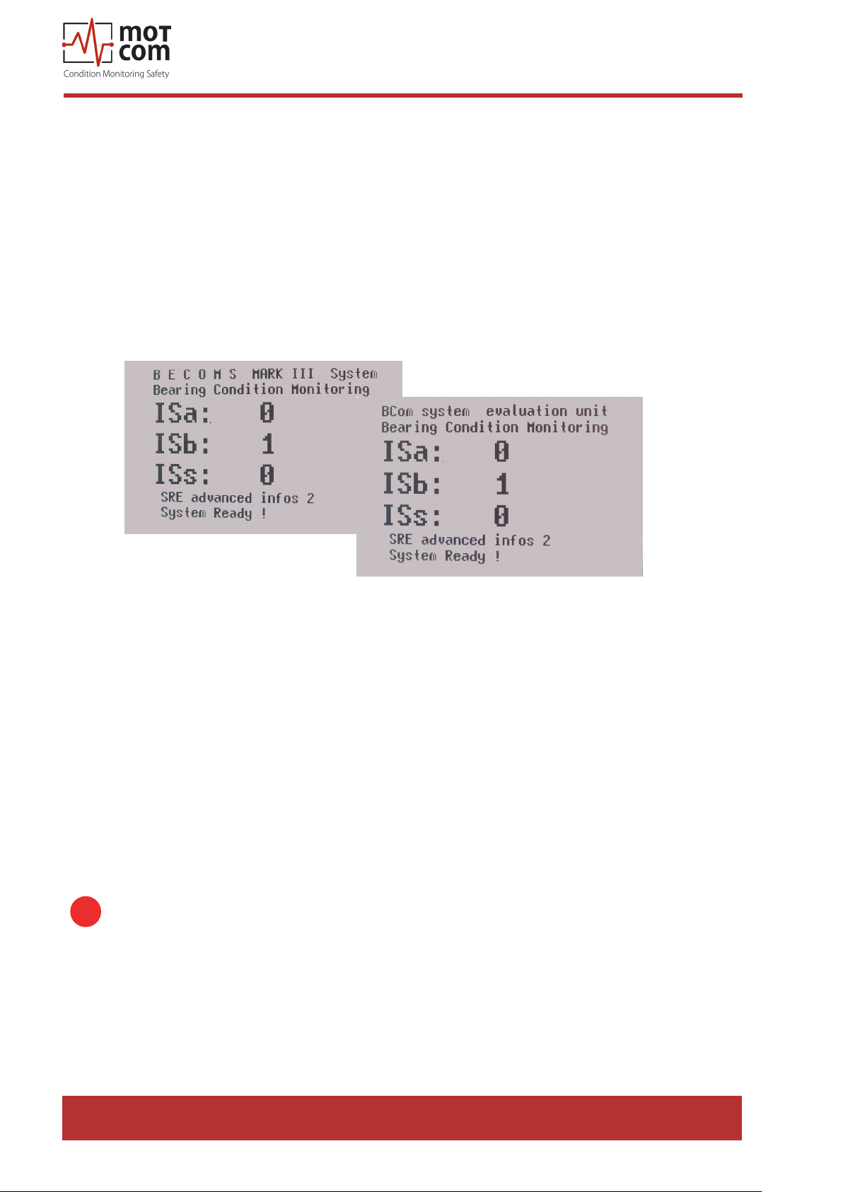
3.6.4.2. SRE advanced infos 2
User Manual
Fig. 3.7. SRE advanced infos 2
ISa: - the current value at the A channel of incremental encoder (can be 1 or 0)
ISb: - the current value at the B channel of incremental encoder (can be 1 or 0)
ISs: - the current value at the 0 channel of incremental encoder (1 or 0)
3.6.5. Parameter setup
Provides access to BCom parameters, Evaluator settings and test features for
viewing and changing.
3.6.5.1. Setup Parameter
View and change BCom parameters.
i
If the sublevel was entered, pressing [Esc] restarts the Evaluator.
Page 3.10
Release 130301 (revision 190211)
Page 39
motcom® BeCOMS® | BCom
User Manual
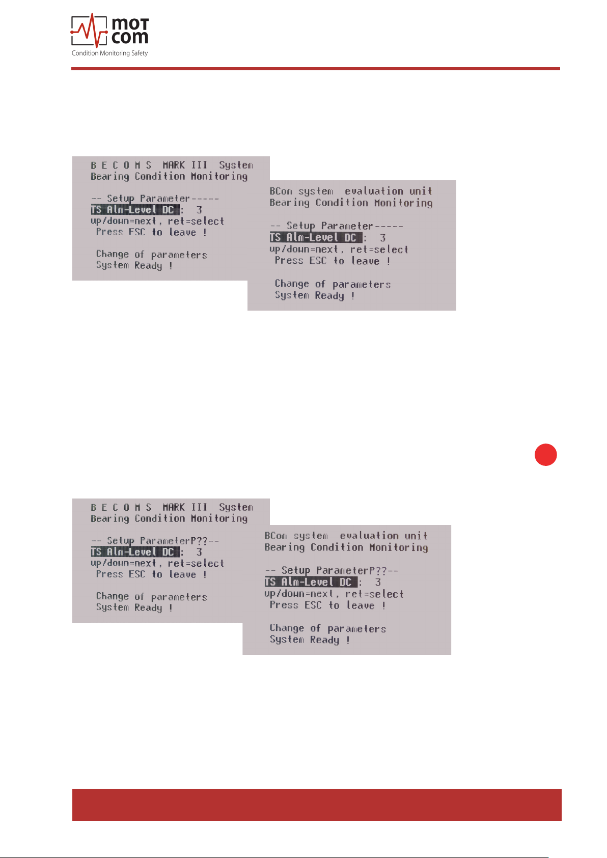
3.6.5.1.1. TS Alm-Level DC:
The value of DC main alarm level in the range of 0 to 5. The higher the value, the
less sensitive is the system. The 0 value disables the DC alarm.
Fig. 3.8. Setup Parameter: thermosignal
To change displayed value: press [Enter], the value eld becomes highlighted. Use
[▲] and [▼] buttons to increase or decrease the number in the eld or to select one
of provided text values. When the desired value appears in the eld, press [Enter]
again.
The value will be successfully changed then if the correct PIN was entered before
in “Setup CPU” menu. Otherwise, the selected screen will display “P??” as shown
below:
i
Fig. 3.9. BCom system measured values, second screen
Please refer to chapter 3.6.5.2.5. “PIN for Setup” for PIN setting instructions.
Release 130301 (revision 190211)
Page 3.11
Page 40

motcom® BeCOMS® | BCom
User Manual
3.6.5.1.2. TS PreAlm-Level:
The value of DC pre-alarm level in percents of DC main alarm.
Possible values: 40 to 100.
3.6.5.1.3. RPM Alarm-Level:
The value of overspeed alarm in RPM. Possible values: 0 to 3000, step 50.
The 0 value disables the alarm.
3.6.5.1.4. TS Alm-Level1 AC:
The value of AC main alarm level in the RPM zone 1. Possible values: 0 to 5.
The 0 value disables the alarm.
3.6.5.1.5. TS Alm-Level2 AC:
The value of AC main alarm level in the RPM zone 2. Possible values: 0 to 5.
The 0 value disables the alarm.
3.6.5.1.6. RPM for Level2:
Engine rotation speed in RPM which denes the boundary between RPM zone 1
and RPM zone 2.
3.6.5.1.7. Start Alminhibit:
Time interval in seconds immediately after engine start during which the main alarm
is disabled.
3.6.5.1.8. TS Test Time:
Time interval between test pulses, possible values: 1 min to 10 min. Test pulses
help to check if the SRE sensor functions correct.
3.6.5.1.9. TS Test Len:
The length of test pulse. Possible values: 1 s to 15 s.
Page 3.12
3.6.5.1.10. IS Impuls Oset:
The oset between TDC of cylinder 1 and the synchronisation pulse at the
channel 0.
This value cannot be set at the Evaluator using the “Up” and “Down” buttons. It is
used during the impulse oset setup procedure as an indicator.
To start the procedure, a special PIN must be entered (see chapter 3.6.5.1.11.,
page 3.13)).
Release 130301 (revision 190211)
Page 41

motcom® BeCOMS® | BCom
User Manual
3.6.5.1.11. PIN Impuls Os.:
PIN for impulse oset setup, the procedure is the same as described in chapter
3.6.5.2.5
3.6.5.1.12. TSe ena for DC:
Enable or disable (values 1 and 0 accordingly) calculating eective value of
thermosignal in percents of DC alarm level.
3.6.5.1.13. Values for TSe:
Number of points for calculating eective value of thermosignal in percents of DC
alarm level.
3.6.5.1.14. DC Alarm percent:
Scale factor for DC alarm level, possible values: 80% to 199%.
3.6.5.1.15. AC Alarm percent:
Scale factor for AC alarm level, possible values: 80% to 199%.
3.6.5.2. Setup CPU
View and change Evaluator settings.
If the sublevel was entered, pressing [Esc] restarts the Evaluator.
3.6.5.2.1. LCD brightness:
Brightness of Evaluator LCD display in the range of 5 to 100. The higher the value,
the brighter is the display.
3.6.5.2.2. RS485 fullduplex:
RS485 transmission mode. Possible values:
OFF: two-wire mode. Sending and receiving data simultaneously is not possible.
ON: four-wire full-duplex mode. Allows communication in both directions
simultaneously.
i
3.6.5.2.3. Modbus enable:
Enable or disable (values ON and OFF accordingly) the Modbus interface.
3.6.5.2.4. Modbus adress:
Modbus address in the range of 0 to 99.
Release 130301 (revision 190211)
Page 3.13
Page 42
motcom® BeCOMS® | BCom
User Manual
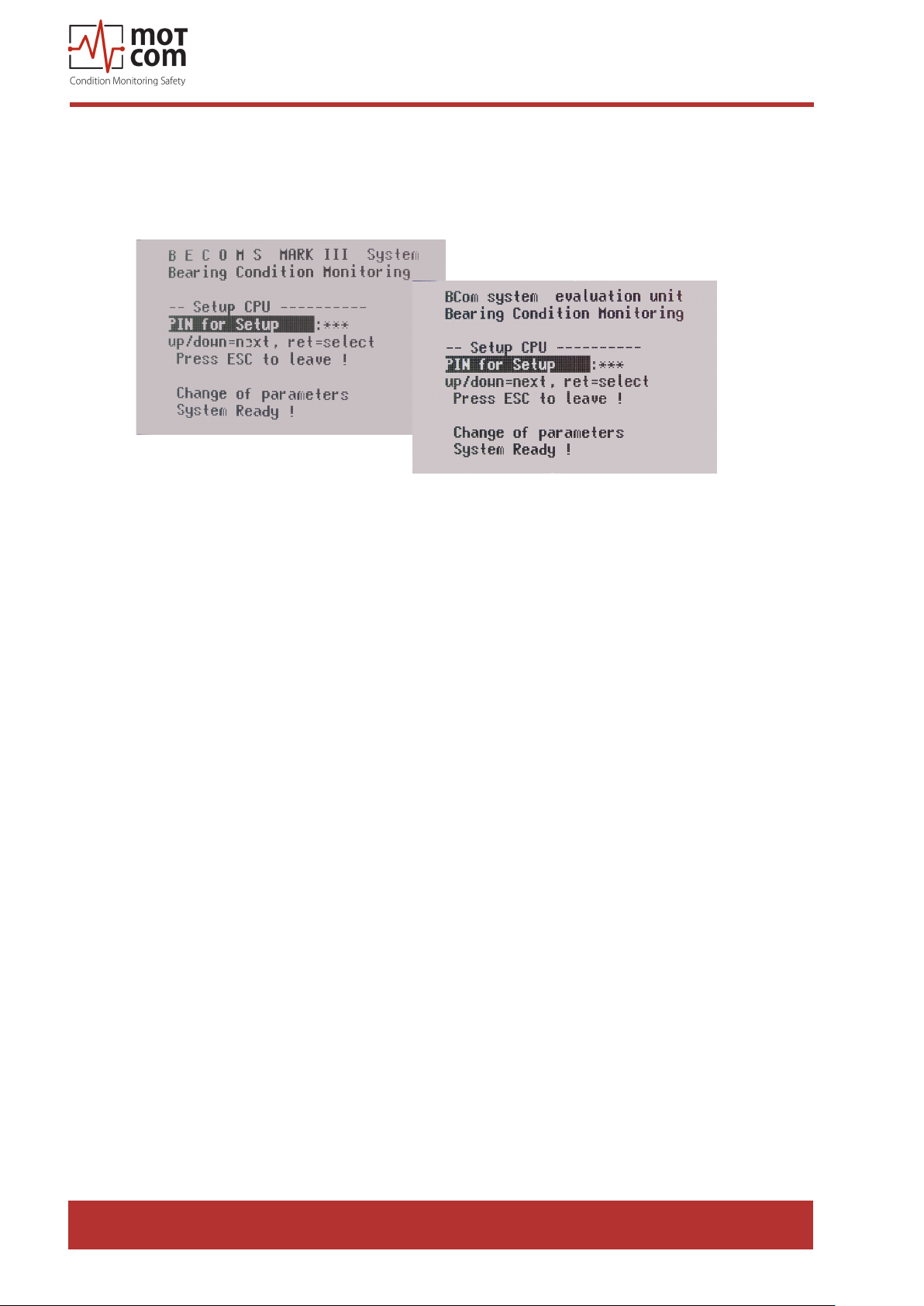
3.6.5.2.5. PIN for Setup:
PIN for enabling write access to menu items in “Setup Parameter”, “Setup CPU”
and “Test Features”.
Fig. 3.10. BCom PIN for setup
To enter PIN: press [Enter], the PIN eld becomes highlighted. Use [▲] and [▼]
buttons to increase or decrease the value. When the correct PIN appears in the
value eld, press [Enter] again. The screen at g. 3.9., page 3.11 appears then,
and the system parameters can be changed now. If wrong PIN was entered, text in
the PIN eld will be changed to “P??”.
3.6.5.2.6. Software Info:
Firmware version of the Evaluator (read-only).
3.6.5.3. Test Features
View and use test features of the Evaluator. To get access to this menu, a PIN must
be entered (see 3.6.5.2.5.).
3.6.5.3.1. Ready Relay:
Switch the Ready relay ON and OFF
Page 3.14
3.6.5.3.2. Alarm Relay:
Switch the Alarm 1 relay ON and OFF.
3.6.5.3.3. Alm2/Pre Relay:
Switch the Alarm 2 relay ON and OFF.
Release 130301 (revision 190211)
Page 43

motcom® BeCOMS® | BCom
User Manual
3.6.5.3.4. Testsignal A:
Switch the test signal on channel A ON and OFF.
At the same time the values TS1 and TS2 are displayed (signals from the rst and
the second thermovoltage measurement channels).
3.6.5.3.5. Testsignal B:
Switch the test signal on channel B ON and OFF.
At the same time the values TS1 and TS2 are displayed (signals from the rst and
the second thermovoltage measurement channels).
Release 130301 (revision 190211)
Page 3.15
Page 44

motcom® BeCOMS® | BCom
User Manual
3.7. BCom Data_Logger measurement data storage and management
(optional)
BCom Data_Logger is a PC program for displaying and storing the measured data.
i
Info: For detailed information on BCom Logger software please refer to BCom
Data_ Logger user manual.
BCom Data_Indicator software is used for reading and analysing the BCom data
les. For further information please refer to BCom Data_Indicator user manual.
The daily data les created by BCom Logger have an approximate size of 80MB
per BCom set. To save hard disk space, older les can be deleted, compressed
and/or archived on CD. By compressing a daily log-le with WinRAR, WinZip or
other suitable software, the size of the le can be reduced to approx. 8MB.
WinRAR shareware is usually pre-installed on the monitoring PC.
Page 3.16
Release 130301 (revision 190211)
Page 45
motcom® BeCOMS® | BCom
User Manual
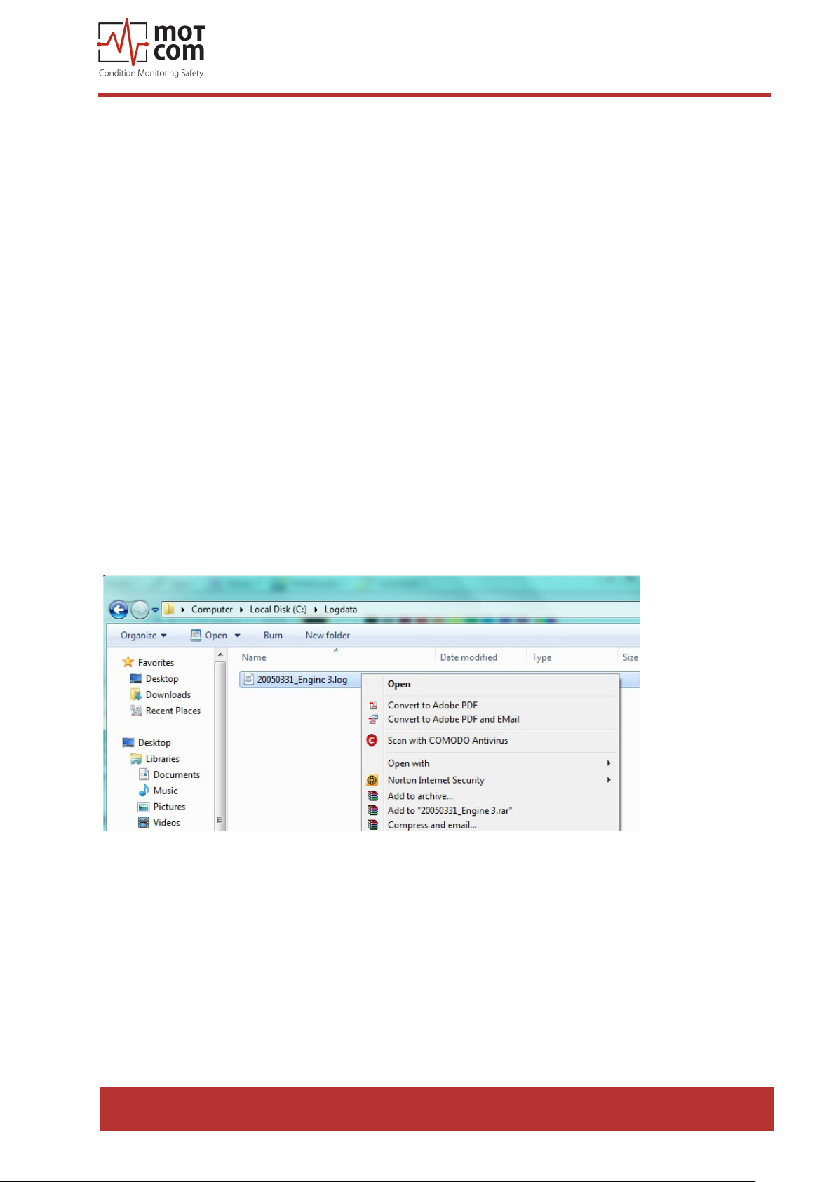
3.7.1. Compressing Data Files
To compress daily data les with the le extension *.log to *.rar
* symbolizes the name of the data le, which is usually given systematically as follows:
YYYYMMDD_EngineXXX, i.e. 20050331_EngineXXX,
whereas
YYYY: year, i.e. 2005
MM: month, i.e. 03
DD: day, i.e. 31
of the BCom set on the Engine XXX
using “WinRAR” follow these instructions:
1) Click on the desired data le which is to be compressed with the right button of
the mouse. A menu should pop up (refer to Fig. 3.11.).
2) Click on the option “Add to Archive” from the option list.
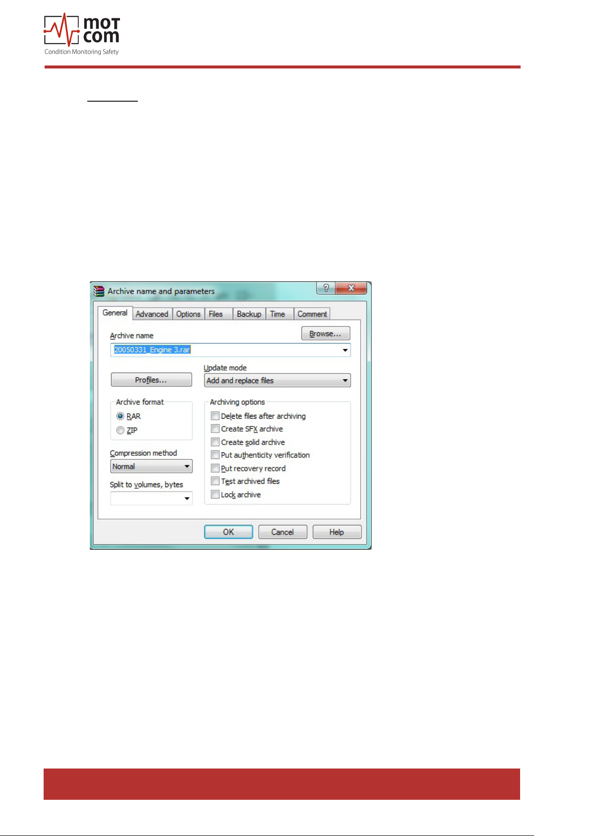
3) Click “OK” (refer to Fig. 3.12.) and the data le *.log will be automatically
compressed and a new le *.rar with the same prex-le name will be created.
4) Each log le can be compressed into a single le by repeating the steps 1&2 by
selecting the log les *.log one by one.
5) If multiple log les are to be compressed into a single rar-le, repeat the above
steps 1&2 by selecting all desired log les at once.
Fig. 3.11. Screenshot
Release 130301 (revision 190211)
Page 3.17
Page 46
motcom® BeCOMS® | BCom
User Manual
Remarks:
Standard settings of the application software “WinRAR” to compress the data les
may not be modied:
1) Archive format: RAR
2) Update mode: Add and update les
3) Archiving option: no tag selected
4) Compression method: best
5) Volume size: not limited
6) The original of the data les, which have been compressed, will not be deleted
automatically.
Page 3.18
Fig. 3.12. Screenshot
Release 130301 (revision 190211)
Page 47

motcom® BeCOMS® | BCom
User Manual
3.7.2. Capturing the Graphic Screens
To capture and archive the window screens with the graphical trends of the BCom
signals in daily graphic les with the le extension *.doc using “MS-Word” proceed
as follows:
A) Preparing/creating a new daily screen le with the le extension *.doc
* symbolizes the name of the daily screen le to be chosen, which should be normally
named systematically as follows:
YYYYMMDD_EngineXXX, i.e. 20050331_EngineXXX, whereas
MM: month, i.e. 03
DD: day, i.e. 31
YYYY: year, i.e. 2005
1) Please click “start” with the left button of the mouse
2) and go to “Documents” and
3) click “my document” with the left button of the mouse
4) Select “Blank template for graphic screens” by clicking it with the left button
of the mouse twice!
5) Go to “File” in the menu bar and then click “save as”
6) Please type the name “D:\Archive_monthly_data YY.MM\YYYYMMDD_
EngineXXX”, whereas “D:\Archive_monthly_data YY.MM” is the monthly
archive directory and “YYYYMMDD_EngineXXX” as described above; and
click “save”.
B) Then please minimize all other software applications except BCom monitoring
application (so that you can get a clear screen without unnecessary windows at
the back ground of BCom monitoring application).
C) Select the part of the diagram you want to save.
D) Press the “Print Scrn”-button of the keyboard once.
E) Then Click the MS-word *.doc le icon in the bottom menu bar, so the
YYYYMMDD_EngineXXX.doc will open.
F) Point to the position you want to insert the captured screen.
G) Click the right button of the mouse and click “Paste” from the menu by clicking
the left button of the mouse.
H) Then the captured screen will be inserted in the doc-le, please resize it
according to your need and if necessary please add remarks to the just inserted
graphic clips.
I) Please repeat the steps B to H until you have saved all the graphic parts you want
(Hints: It is better to keep the graphic curves parts in chronological sequence).
J) Then save and close the YYYYMMDD_EngineXXX.doc
To reduce the le size; the YYYYMMDD_EngineXXX.doc les can also be
compressed using the same method described in chapter “3.7.3. Archiving the
Compressed Files” on page 3.20
Release 130301 (revision 190211)
Page 3.19
Page 48

motcom® BeCOMS® | BCom
User Manual
3.7.3. Archiving the Compressed Files
To move the compressed data-les *.rar from the daily directory to the monthly
archive directory or other storage media (D:\Archive_monthly_data YY.MM, whereas
MM: month, i.e. 03; YY: year, i.e. 05,) proceed as follows:
1) Select all the data-les *.rar to be moved by marking the rst data-les *.rar
by
a. pointing to the rst data-le *.rar to be moved and
b. pressing the left button of the mouse once and then press the “Shift-
button” of the keyboard, hold it and move the mouse pointer to the last
data-les *.rar to be moved and
c. press the left button of the mouse once again and release the “Shift-
button”. All the selected data-les *.rar change the colour.
2) Then click the right button of the mouse.
3) Select (by pointing and click the left button) the option “cut” from the pop-up
option list.
4) Move the pointer to the monthly archive directory (D:\Archive_monthly_data
YY.MM) and select it by clicking the left button of the mouse once.
5) Then click the right button of the mouse.
6) Select (by pointing and click the left button) the option “paste” from the popup option list.
7) All the selected data-les *.rar will be moved to the monthly archive directory.
Page 3.20
Release 130301 (revision 190211)
Page 49

motcom® BeCOMS® | BCom
User Manual
3.7.4. Manual Data Analysis for Compartment Localization
As described in chapter 1.1.1. “BCom Principle” on page 1.1, the faulty parts will
produce higher thermovoltage signal due to high pressure during ring in the aected
cylinders. BCom Data_Logger software displays the polar log data superposed
with the cylinder numbers. This allows a trained engine operator to recognise the
following possible causes of the high thermosignal:
• friction between the rotating crankshaft and its bearings. In this case it is possible
to identify:
- compartment where the failure has occured,
- the bearings that are aected
• other moving parts not related to the rotating crankshaft. Having experience with
this cetain engine type, the operator can identify:
- the exact parts that cause the high thermosignal.
To get reliable failure localization results, a continuous time interval should be
analysed in the logle recorded on the day when failure was registered.
Attention
A general description cannot be given at this point, because the form of thermo
voltage signals in BCom varies depending on the type of engine and application.
In the training session after the commissioning, the engine operators will be trained
intensively to perform the localization of faulty compartment and parts specically
to their engines.
If no such trained person is available, or if he or she was not able to nd the problem,
please contact motcom GmbH or its representatives for further analysis of your
measurement data.
Attention: Please do not send the log le immediately in your rst email to us. You
will get further information after contacting us.
!
Release 130301 (revision 190211)
Page 3.21
Page 50

motcom® BeCOMS® | BCom
User Manual
Page 3.22
Release 130301 (revision 190211)
Page 51

motcom® BeCOMS® | BCom
User Manual
4. Performance / Maintenance Tests
4.1. Function Test
During operation BCom transmits test signals to the crankshaft at regular intervals.
These signals are displayed depending on the operating state:
1. if the engine runs its crankshaft is electrically isolated from bearings with the
lubrication oil lm. Test signals are visible among measurement data.
2. on the stopped engine the crankshaft makes electrical contact with the
bearing. Test signals are not visible.
The test signals will not be visible either, if the test signal option in the Data_Logger
software is disabled. If this option is disabled, the test signal will not be displayed
nor stored to the daily log le. This means, that you cannot activate the display of
the test signal in Data_Indicator later.
Release 130301 (revision 190211)
Page 4.1
Page 52

motcom® BeCOMS® | BCom
User Manual
Page 4.2
Release 130301 (revision 190211)
Page 53
motcom® BeCOMS® | BCom
!
User Manual
5. Troubleshooting
CAUTION
The manufacturer’s warranty will become void if
• the BCom Evaluator was modied without permission or
• the BCom Slip Ring Encoder was opened!
5.1. During Software Installation
The BCom Data_Logger and Data_Indicator software is designed and tested to run
under the following Microsoft operating systems:
• Windows 7
• Windows 8.x
• Windows 10
Please refer to chapter 2.6 on page 2.6 for requirements to the personal computer
needed for the software.
If a “Not connected” message appears in the event window after you have started
“BCom Data_Logger”, the following steps may x the problem in case the RS-485
converter is used:
• Is the RS-485 converter’s green power-LED on? Check the power supply.
• Is the wiring of the RS-485 interface reversed (connection A and B).
This is the most common cause of error!
• Is the RS-485 converter connected to the correct COM port? If connected
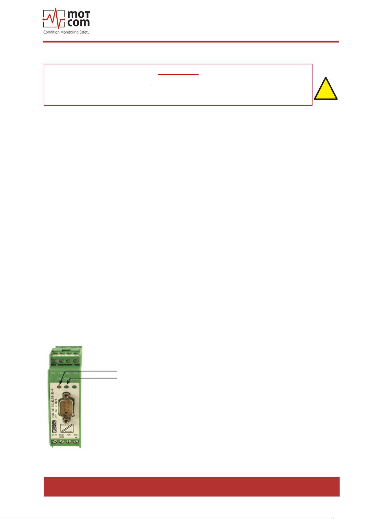
correctly, the transmit LED (TX) (Fig. 5.1) should blink after measurement
start to indicate that computer is sending data.
• If the connection is established, this is conrmed by a “Connected” message
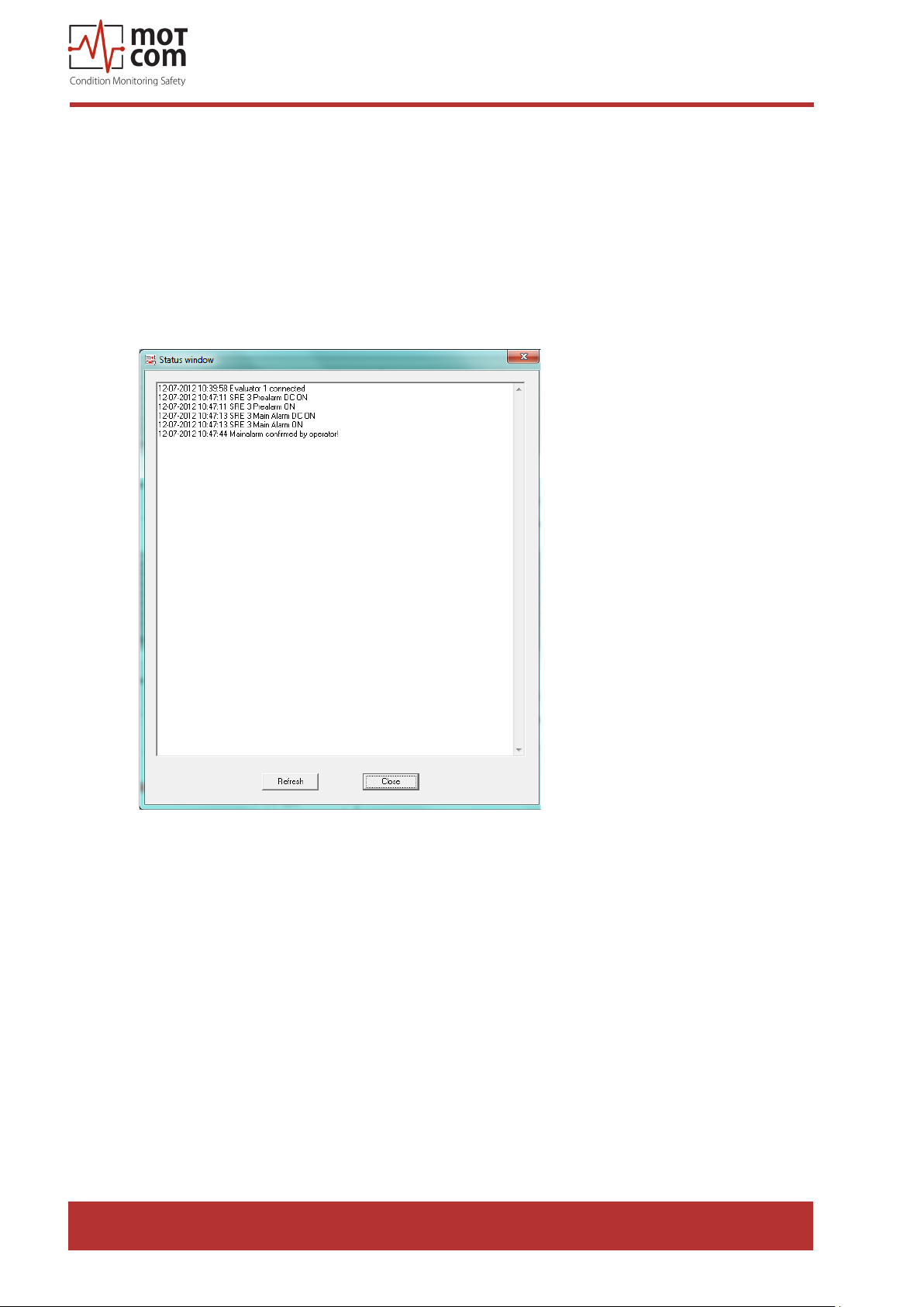
in the event window. (Fig. 5.2)
TX LED
RX LED
Fig. 5.1. RS-485 converter
Release 130301 (revision 190211)
Page 5.1
Page 54
motcom® BeCOMS® | BCom
User Manual
5.2. During Software Use
The error messages displayed in BCom Data_Logger are self-explaining, i.e. a
communication problem with the BCom Evaluator is depicted in Fig. 5.2. below.
The operators should use the technical acceptable standards to trace the cause of
the errors reported and skillfully x the problem. If the problem cannot be solved,
please contact motcom GmbH authorized representatives.
Page 5.2
Fig. 5.2. Example of messages displayed in the event window /
status window
Release 130301 (revision 190211)
Page 55
motcom® BeCOMS® | BCom
User Manual
5.3. Missing Control Signal
1. If the green READY LED of the BCom Evaluator is o and the thermo voltage
signal and/or RPM are displayed as zero or unstable on the LCD-display of
the Evaluator (and in BCom Data_Logger) at a running engine, then please
conduct the following steps:
1) Check if cable connectors at the cable connecting SRE and the Evaluator are
loose, if necessary, x them
2) If this can not solve the problem, please check the error message reported
and contact motcom GmbH or its authorized representatives.
2. If the green READY LED of the BCom Evaluator is on, but only the thermo
signal and no RPM is displayed on the LCD-display of the Evaluator (and in
BCom Data_Logger) at a running engine, then please conduct the following
steps:
1) Remove the interface housing cover
2) Check whether the metal coupling inside is turning with the engine
3) If it is not turning, retighten it with the necessary torque of 40Nm
4) If the coupling is turning, check if cable connectors at the cable connecting
SRE and the Evaluator are loose, and if necessary, x them
5) If you could not solve the problem, please check the error message reported
and contact motcom GmbH or its authorized representatives
Attention: If you have retightened the metal coupling the synchronization
steps in chapter “2.3 SRE Mechanical Adjustments” on page 2.3
have to be done!
!
Release 130301 (revision 190211)
Page 5.3
Page 56

motcom® BeCOMS® | BCom
User Manual
5.4. Very low / strong signal on polar diagram
The bearing monitoring by a BCom sensor is a relative measurement.
The recording and interpretation of the signals over a longer period is important.
Changes of the signal could be evaluated based on the previous recorded data.
Based on these results suitable measures for engine operation, lubricating oil care
or others will derive.
Page 5.4
Release 130301 (revision 190211)
Page 57

motcom® BeCOMS® | BCom
User Manual
5.5. Error code and Error description
The following messages displayed on the LCD screen of the BCom Evaluator are
possible.
System Ready!
Standard message indicating that the system works and all measured values are in
the permitted range.
BCom - Error 04
First pulse sequence of incremental encoder - not connected
BCom- Error 08
Second pulse sequence of incremental encoder - not connected
BCom - Error 16
Synchronization signal of the incremental encoder - not connected
BCom - Error 32
BCom test-signal dead, check all connections
The error codes may be summed up! For example, error code 20 means that the
error codes 04 and 16 appeared together.
Possible combined codes are shown on the table on the next page.
BCom- Error 99
SRE-Sensor not connected
CPU Error xxx
A CPU error means an error from the EEPROM. This error appears also due to
incorrect or incomplete parametrization. Should this error not be xed after correcting
the parameters and restarting please contact the manufacturer or the maintenance
service, providing the error code.
i
01 xx Check parameters of CPU (...)
02 xx Check parameters of BCom (...)
Release 130301 (revision 190211)
Page 5.5
Page 58

Single codes
32 16 8 4
12 - - x x
20 - x - x
24 - x x 28 - x x x
36 x - - x
40 x - x 44 x - x x
48 x x - -
Summed up codes
52 x x - x
56 x x x 60 x x x x
motcom® BeCOMS® | BCom
User Manual
Table 5.1. Code combinations
Page 5.6
Release 130301 (revision 190211)
Page 59

motcom® BeCOMS® | BCom
User Manual
6. Repair
Before any attempts to repair or dismount the BCom devices because of an assumed
defect or failure you should contact motcom GmbH or its authorized partners.
Based on experience, many failures can be cleared easily by fault diagnostics on
site. In most cases a repair is not necessary.
Dismounting may only be performed on demand by motcom GmbH or its authorized
service representatives.
A repair of BCom components is done exclusively by motcom GmbH. Defective
parts should be sent to motcom GmbH including detailed failure description.
Please get in contact with the headquarter of motcom GmbH for further assistance.
Release 130301 (revision 190211)
Page 6.1
Page 60

motcom® BeCOMS® | BCom
User Manual
Page 6.2
Release 130301 (revision 190211)
Page 61
motcom® BeCOMS® | BCom
7. Spare Parts
Only the original parts supplied and approved by motcom GmbH should be
!
used; otherwise a proper working system could not be assured.
7.1 Main Spare Parts
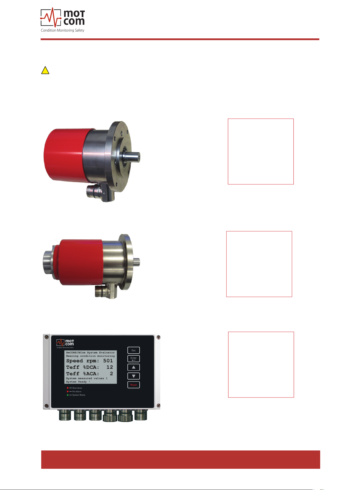
Part No.
1 010 00 20000
User Manual
Fig. 7.1. Slip Ring Encoder (SRE)
Fig. 7.2. Slip Ring Encoder (SRE) with throughout shaft
Part No.
1 010 00 20011
Part No.
1 020 01 00000
Fig. 7.3. BCom Evaluator
Release 130301 (revision 190211)
Page 7.1
Page 62
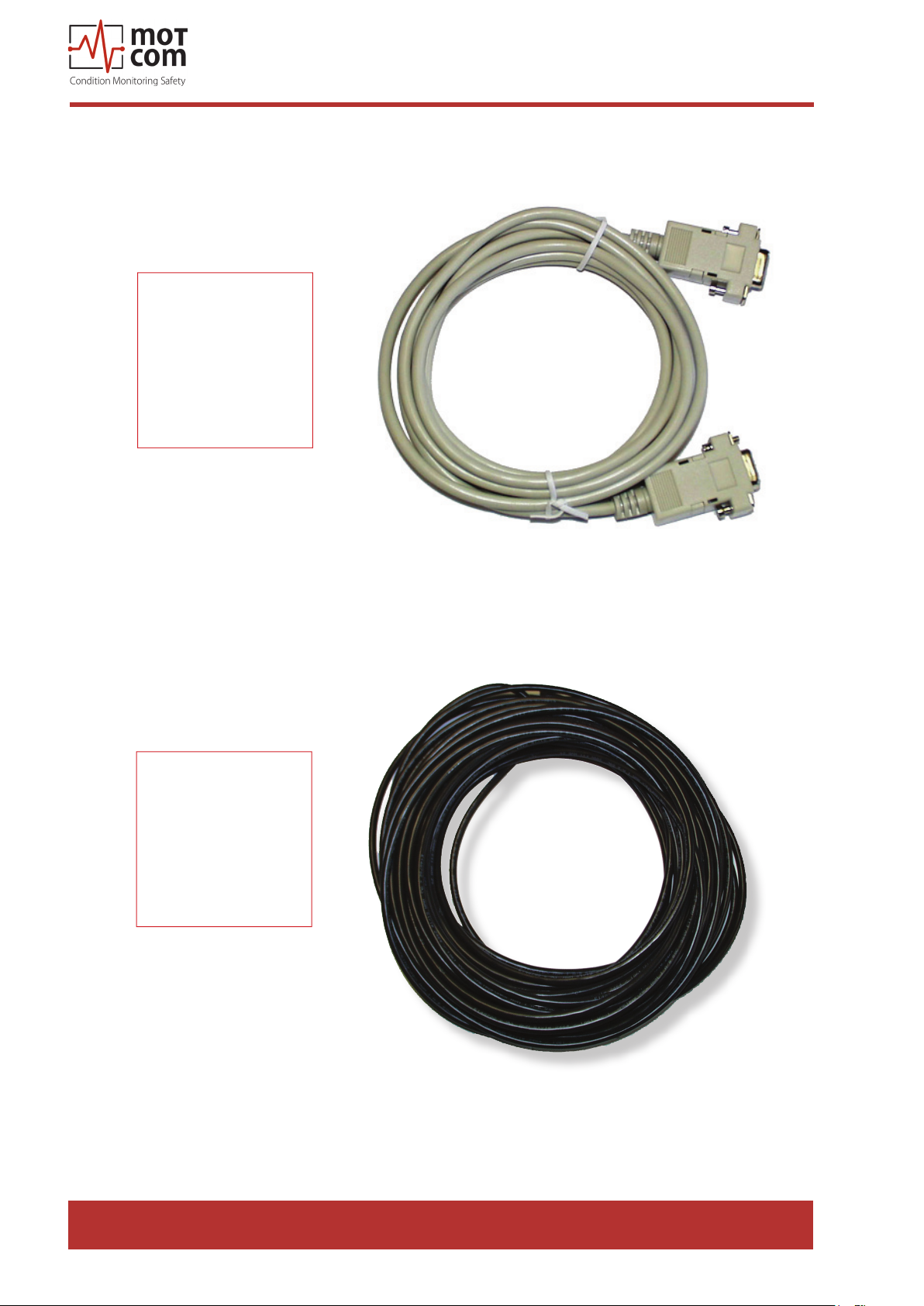
7.2. Accessories
Part No.
9 100 20 00000
motcom® BeCOMS® | BCom
User Manual
Part No.
9 200 04 22000
Fig. 7.4. RS-232 Connection cable for PC to external RS-485
converter
Page 7.2
Fig. 7.5. 2 x 2 twisted pair communication cable
Release 130301 (revision 190211)
Page 63
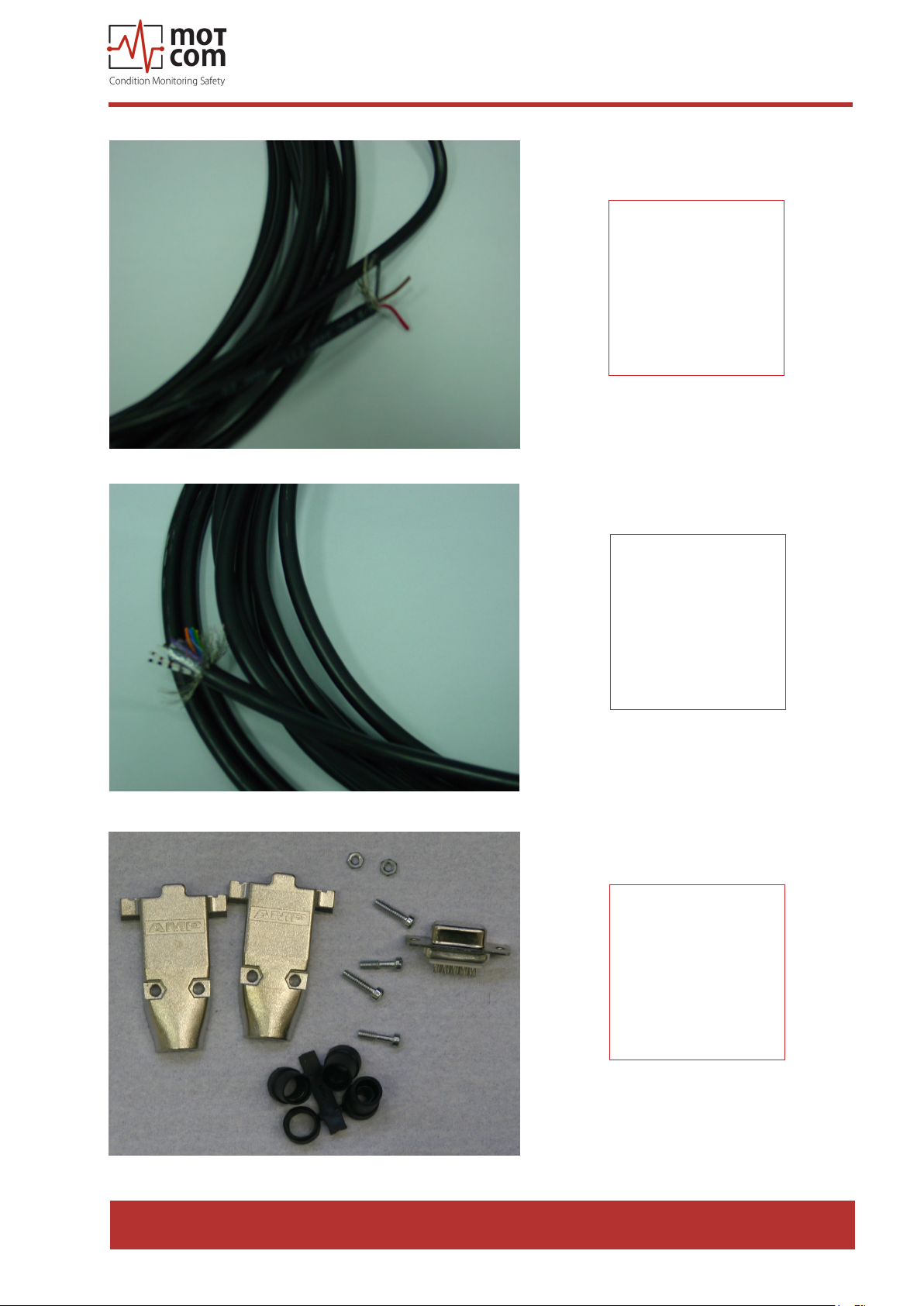
Fig. 7.6. 2 core power cable
motcom® BeCOMS® | BCom
User Manual
Part No.
9 200 02 00000
Fig. 7.7. 12 core communication cable
Part No.
9 200 12 00000
Part No.
9 301 09 10000
Fig. 7.8. Sub-D9 connector
Release 130301 (revision 190211)
Page 7.3
Page 64
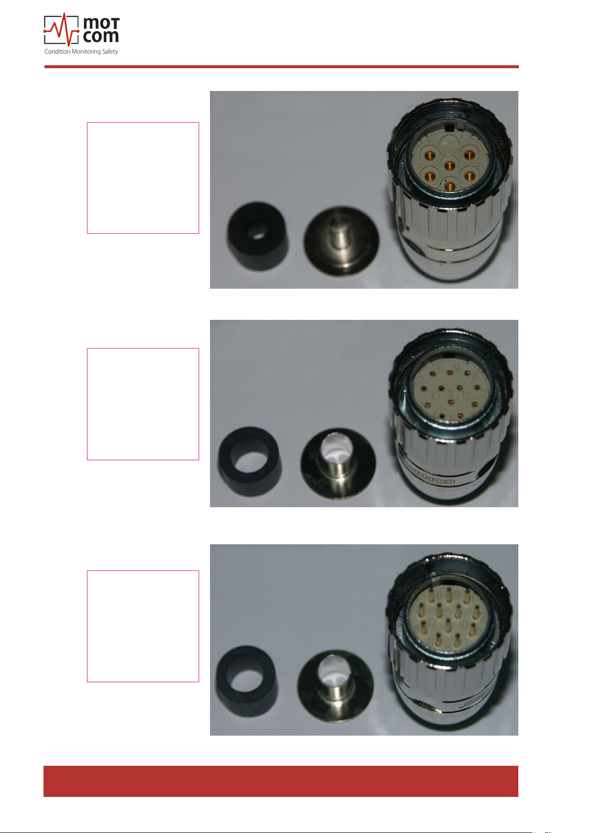
Part No.
9 300 06 10000
motcom® BeCOMS® | BCom
User Manual
Fig. 7.9. 6-pol. female connector
Part No.
9 300 12 10000
Part No.
9 300 12 20000
Fig. 7.10. 12-pol. female connector
Page 7.4
Fig. 7.11. 12-pol. male connector
Release 130301 (revision 190211)
Page 65
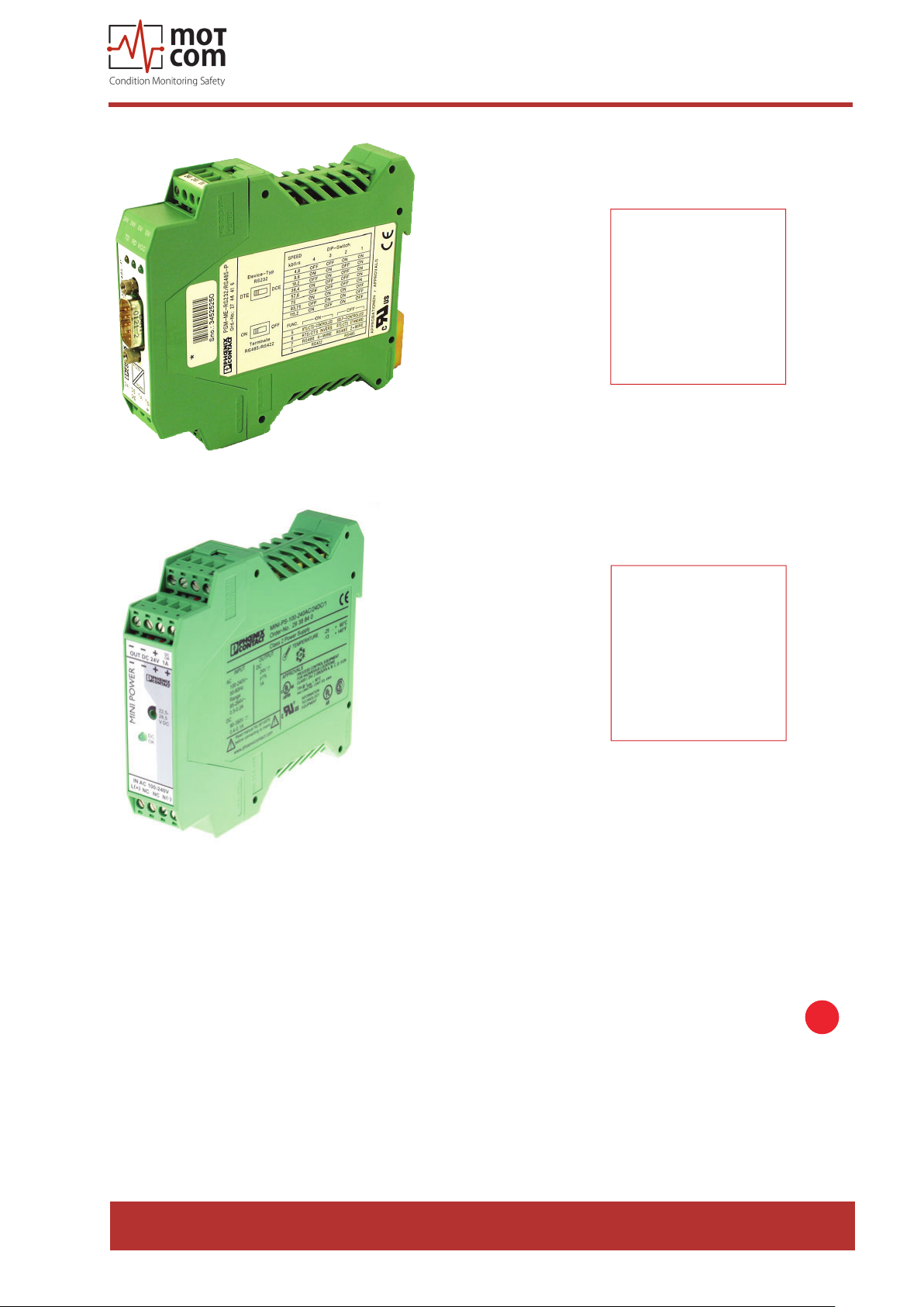
Fig. 7.12. RS-485 converter
motcom® BeCOMS® | BCom
User Manual
Part No.
9 100 30 00000
Fig. 7.13. Power supply unit 24V/24W
Mounting position for
• Part No 9 100 30 00000
• Part No 9 110 40 00000
on horizontal DIN rail NS 35 in acc. with EN 60715
Part No.
9 110 40 00000
i
Release 130301 (revision 190211)
Page 7.5
Page 66

Part No.
9 100 40 00000
motcom® BeCOMS® | BCom
User Manual
Fig. 7.14. RS 485 converter Advantec PCI Card 1602B for
mounting inside PC
Part No.
9 100 40 00010
Part No
9 100 40 00020
Fig. 7.15. RS 485 converter PCI Card EX42062IS for mounting
inside PC
Page 7.6
Fig. 7.16. RS 485 converter PCIe Card Version EX45062IS for
mounting inside PC
Release 130301 (revision 190211)
Page 67
motcom® BeCOMS® | BCom
User Manual
Part No.
1 700 10 01000
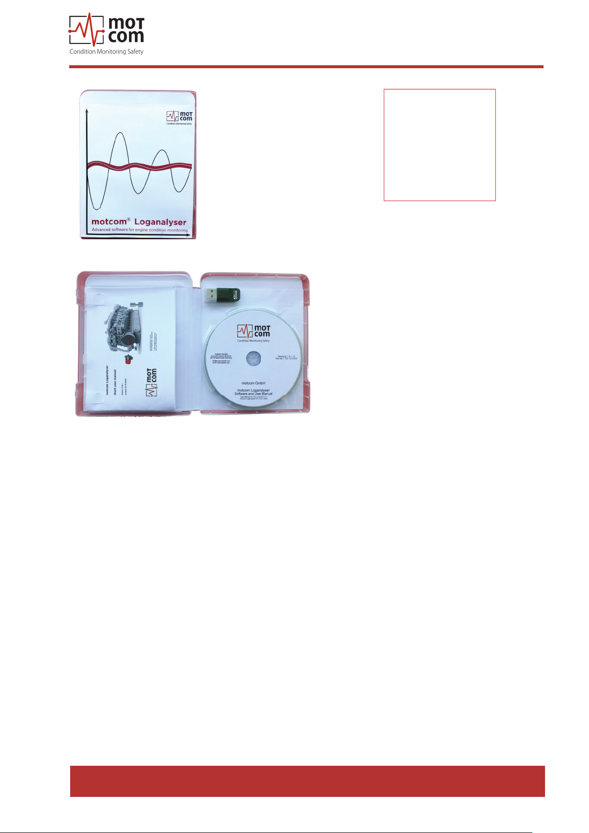
Fig. 7.17. motcom® Loganalyser Software
Release 130301 (revision 190211)
Page 7.7
Page 68

motcom® BeCOMS® | BCom
User Manual
Page 7.8
Release 130301 (revision 190211)
Page 69
8. Attachments
8.1. Connection Assembly Instructions
motcom® BeCOMS® | BCom
User Manual
8.1.1. Preparing the Cable
For RS485-Converter
(Part No. 9 200 04 22000)
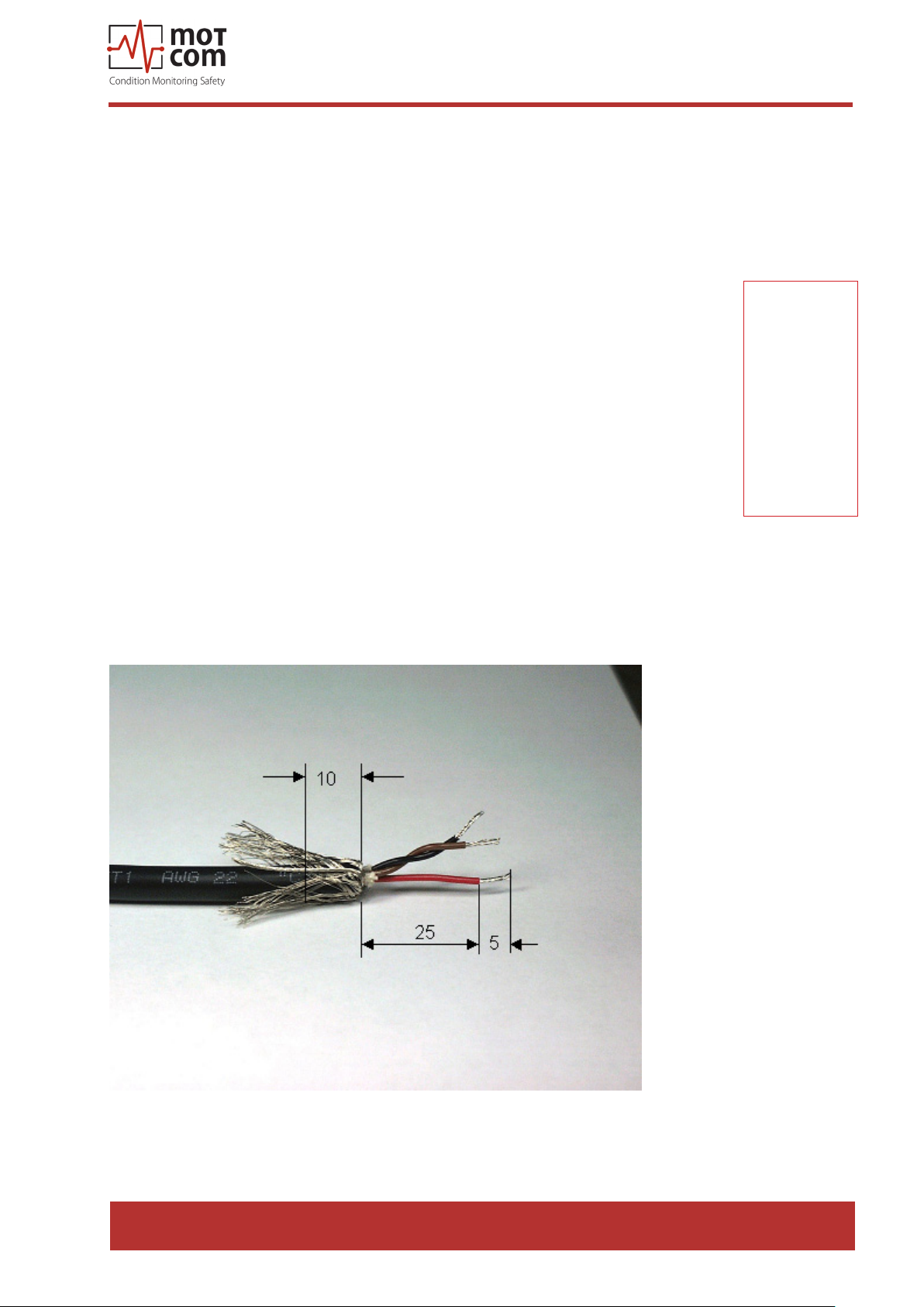
As an example of using 2 X 2 wire twisted cores (Fig 8.1):
• Signal cable: Use a shielded cable, consisting of 2 X 2 wire twisted
pair stranded cores, with each core having a nominal section area of
0.25mm² and overall cable diameter of 8 to 12mm.
• The recommended cable is Metrofunk 2 X 2 AWG 22, (motcom GmbH
Part No. 92000422000) this is used as an example to show how the
connection is made. This cable has 2 twisted pairs of black/brown and
black/red.
• Cut away the outer insulation approx. 25mm from the end of the cable
and pull back the braided shield.
• Cut the braided shield 10mm from the end as shown in Fig. 8.1.
• In this example: Select a twisted pair black/brown and the red wire of
the other twisted pair black/red, and cut away the insulation approx. 5
mm from the end of these 3 wires and solder them to the pins of the
plug (as shown in Fig. 8.3, Pos. 6)
• Cut o the unused wires (in this example, the black wire)
Pay attention to
the assembly
instructions,
especially the
cable shielding
to avoid
electromagnetic
interference!
Fig. 8.1. Preparing the cable
Release 130301 (revision 190211)
Page 8.1
Page 70
motcom® BeCOMS® | BCom
User Manual
8.1.2. Connecting the RS-485 converter
(Part. No. 9 100 30 00000)
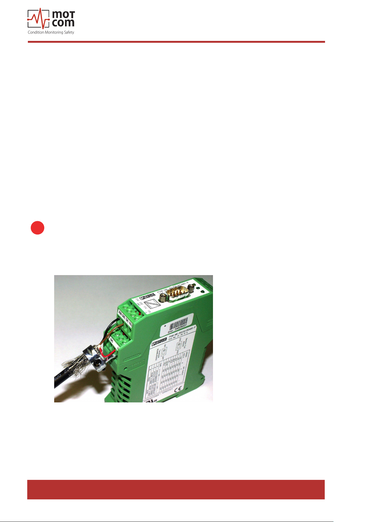
Preparing and Connecting the Cable to the Converter (Fig. 8.2):
• At the free end of the signal cable, the same wires of the twisted pair black/
brown and a red wire of the other twisted pair black/red, should be used.
Please refer to the Section “Preparing the Cable”, page 8.1.
• Cut away the outer insulation approx. 40mm from the end of the cable and
pull back the braided shield (as shown in Fig. 8.1).
• Cut the braided shield 10mm from the end (see Fig. 8.1)
• Cut away the insulation approx. 5mm from the end of these 3 wires.
• Connect the 3 wires to the terminals on the RS-485/RS-232 converter (as
shown in Fig. 8.2).
RS 485 B: brown wire from the black/brown twisted pair to terminal D(B).
RS 485 GND: red wire from the black/red twisted pair to Ground terminal.
RS 485 A: black wire from the black/brown twisted pair to terminal D(A).
Note: If and only if a connection between the PC and BCom could not
i
be established, please swap the signal cables between D(A) and D(B).
• Cut o the unused wires (black wire).
Fig. 8.2. Connecting the RS485 converter
Page 8.2
Release 130301 (revision 190211)
Page 71
motcom® BeCOMS® | BCom
User Manual
8.1.3. Assembling the plug
(Part. No. 9 300 12 10000 and 9 300 12 20000)
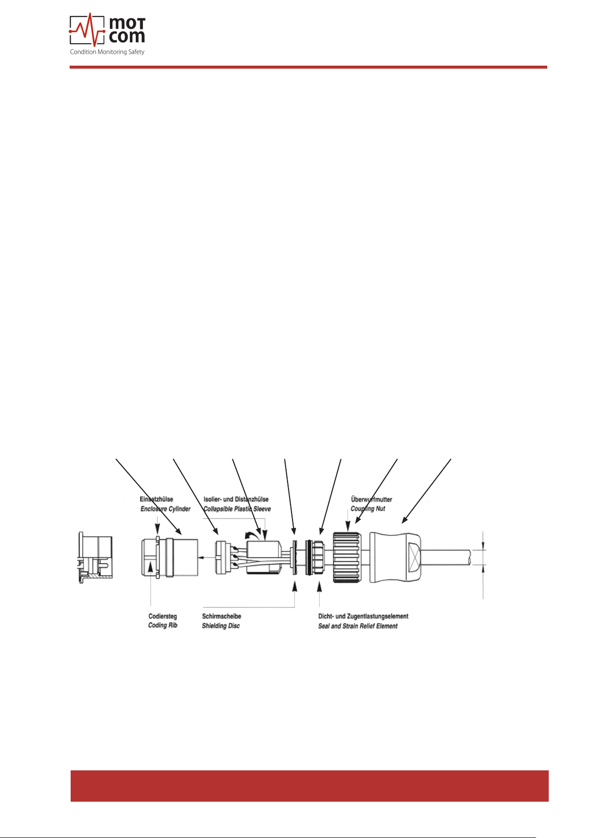
• Push the components over the cable starting with the adapter (Pos. 1),
coupling nut (Pos. 2) and the seal/strain relief element (Pos. 3),
• Cut away the outer insulation approx. 23mm from the end of the cable.
• Push back the braided shield.
• Push the shielding disc (Pos. 4) over the wires and press it against the
braided shield.
• Cut back excess of braided shield close to the shielding disc.
• Cut away the plastic foil, lling material and inner insulation.
• Cut away insulation of wires approx. 3.5mm from the end and twist them.
• Solder brown wire of brown/black pair into pin No. 2 on plug.
• Solder red wire of red/black pair into pin No. 3 on plug.
• Solder black wire of brown/black pair into plug’s Pin No. 4.
• Cut o black wire of red/black pair.
• Add the distance ring (Pos. 5) between the shielding disc (Pos. 4) and insert
ring (Pos. 6).
• Push taper sleeve (Pos. 7) over the insert ring (Pos. 6) and distance ring
(Pos. 5). Make sure the Coding rib is on the right position!
• Push in cable with shielding disc (Pos. 4) and seal and strain relief element
(Pos. 3).
Pos. 7 Pos. 6 Pos. 5 Pos. 4 Pos. 3 Pos. 2 Pos. 1
Fig. 8.3. Mounting the plug part. no. 9 300 12 10000 and 9 300 12 20000
Release 130301 (revision 190211)
Page 8.3
Page 72
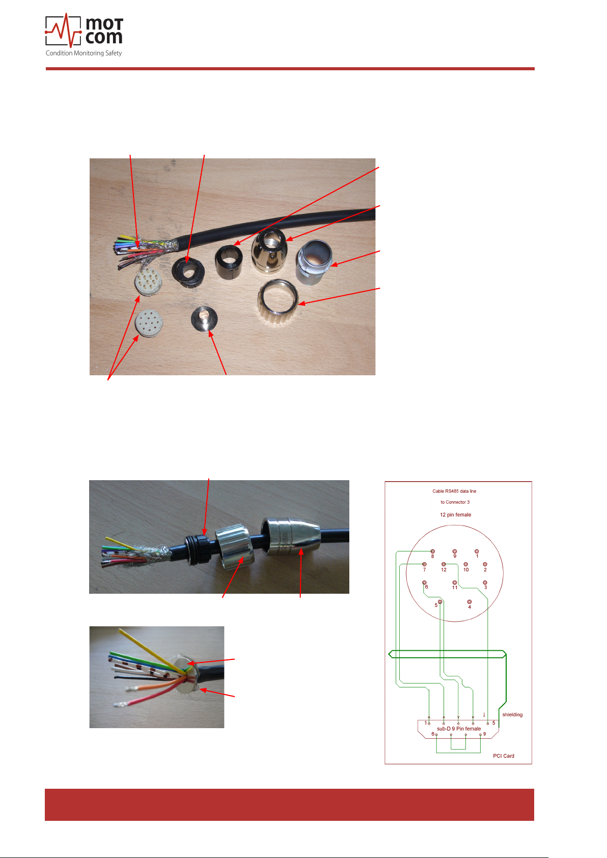
motcom® BeCOMS® | BCom
8.1.4. Connection Cable - RS485 PCI Card to Evaluator
• Cut away the outer insulation approx. 23mm from the end of the cable
User Manual
Cable 12-pin
Connector
Fig. 8.4.Step 1
Sealing and strain relief
Shielding disc
• Push back the braided shield
• Push the sealings over the wires
Insulation and distance sleeve
Connector housing
Enclosure cylinder
Coupling cut
Sealing and strain relief
Fig. 8.5.Step 2a
Fig. 8.6.Step 2b
Coupling nut Connector housing
Shielding disc
Shielding
• Solder wires as shown in Fig 8.7.
Fig. 8.7.Step 3
Page 8.4
Release 130301 (revision 190211)
Page 73
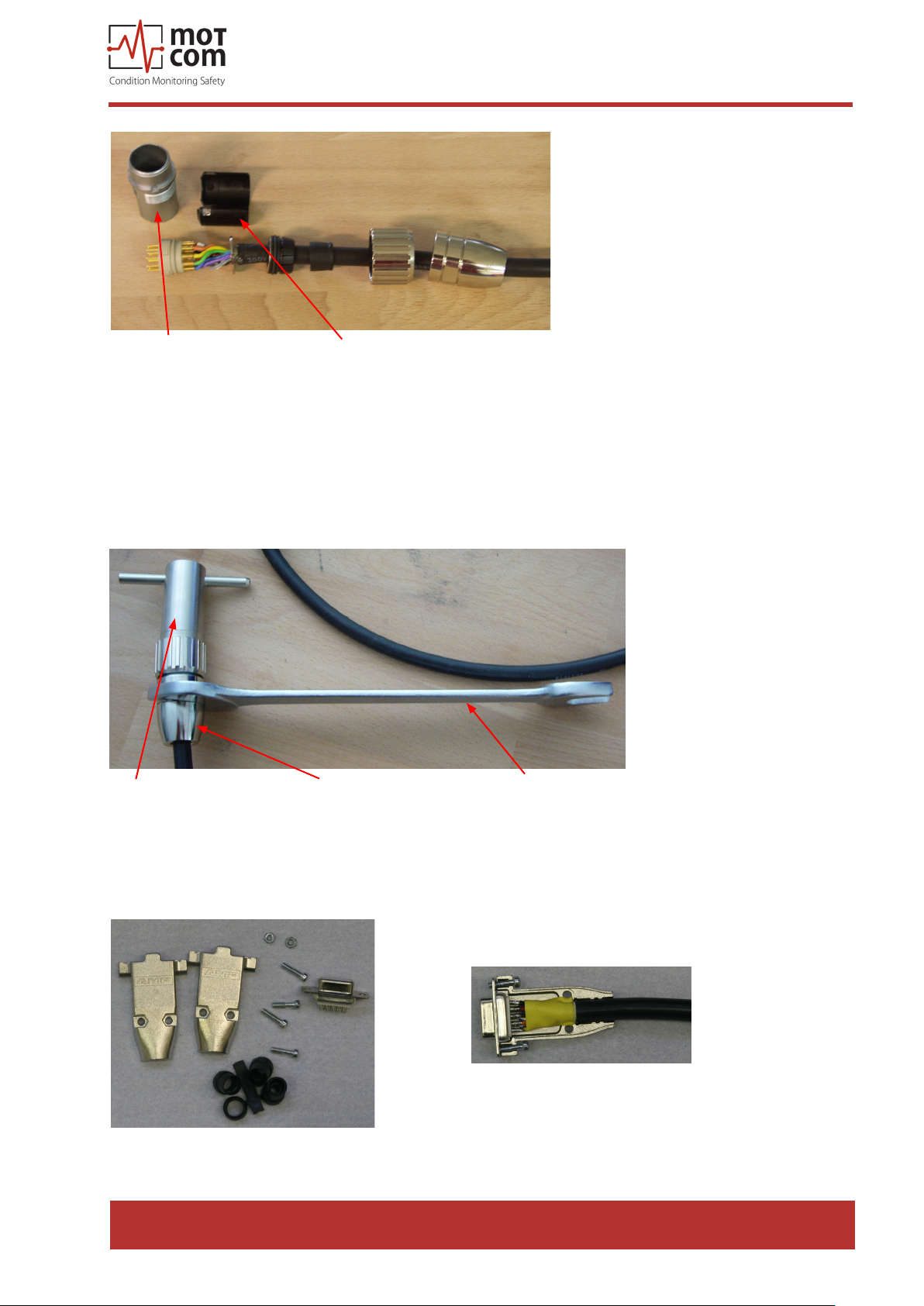
motcom® BeCOMS® | BCom
User Manual
Enclosure cylinder
Fig. 8.8.Step 4
Insulation and distance sleeve
• After soldering, pull the insulation and distance relief over the wires
• Pull the enclosure cylinder over the soldered wires
• Finally, seize the connector housing by using the installation wrench and a at
wrench No. 22
Installation wrench Connector housing Flat wrench No. 22
Fig. 8.9. Step 5
Assemble the Sub-D9 connector on the other side of the cable. (Fig 8.7.) Below,
you’ve got two pictures of the connector before and after assembly.
Fig. 8.11. Sub D9 connector
after assembly
Fig. 8.10. Sub D9 connector before
assembly
Release 130301 (revision 190211)
Page 8.5
Page 74
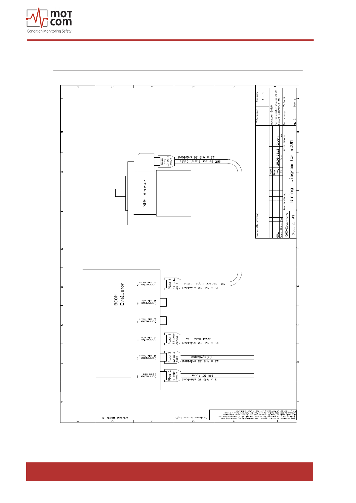
8.2. Wiring Diagrams
motcom® BeCOMS® | BCom
User Manual
Page 8.6
Release 130301 (revision 190211)
Page 75
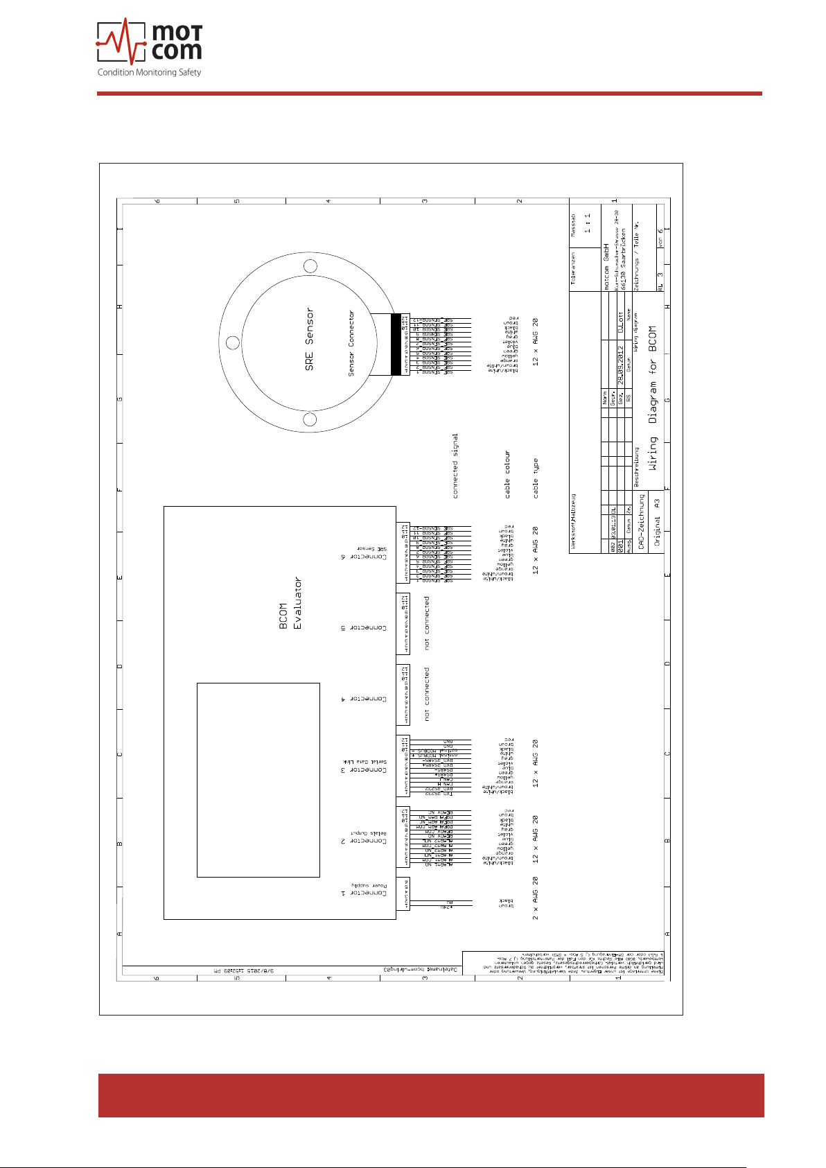
motcom® BeCOMS® | BCom
User Manual
Release 130301 (revision 190211)
Page 8.7
Page 76
motcom® BeCOMS® | BCom
User Manual
Page 8.8
Release 130301 (revision 190211)
Page 77
motcom® BeCOMS® | BCom
User Manual
Release 130301 (revision 190211)
Page 8.9
Page 78
motcom® BeCOMS® | BCom
User Manual
Page 8.10
Release 130301 (revision 190211)
Page 79
8.3. Drawings
motcom® BeCOMS® | BCom
User Manual
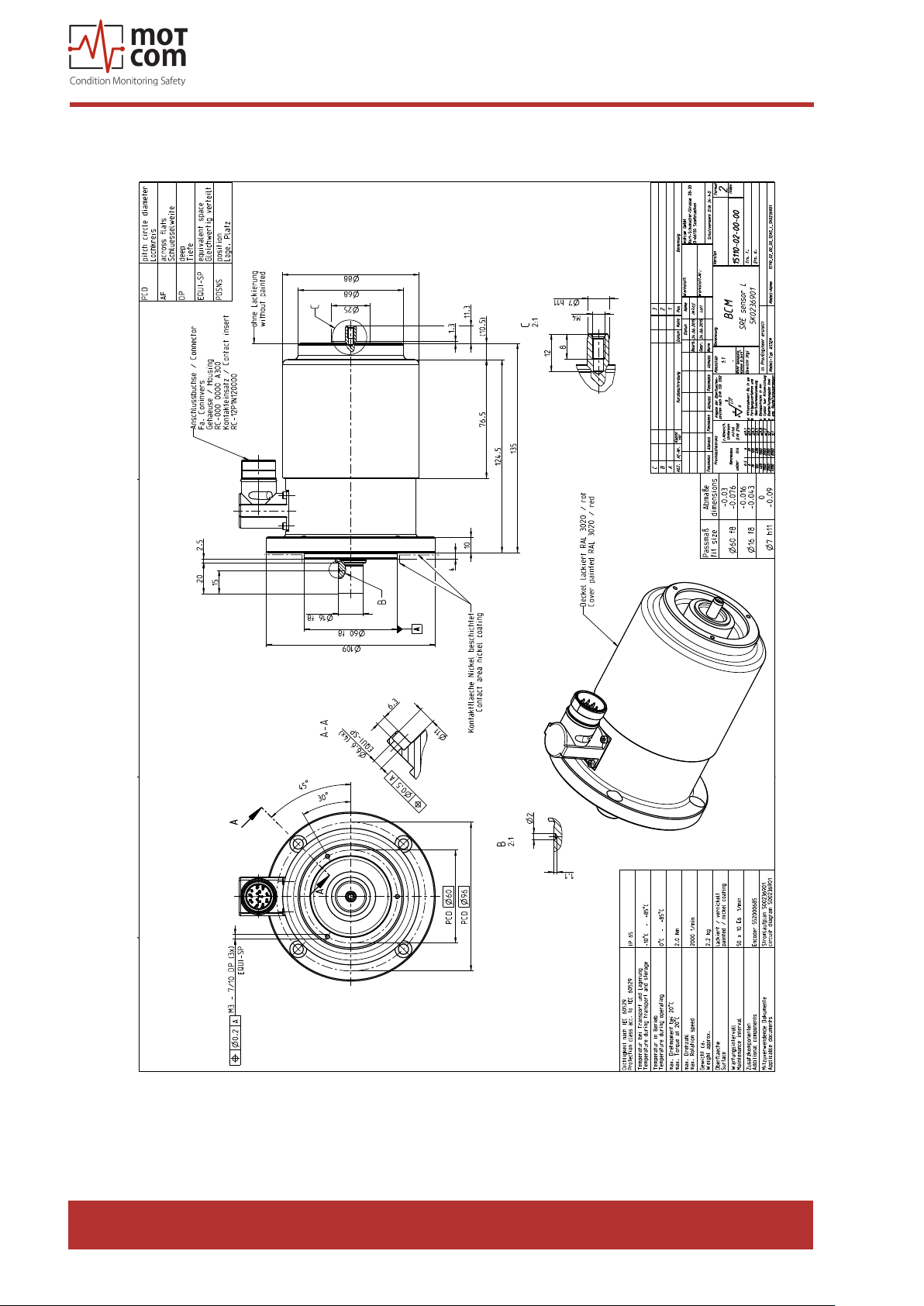
Fig. 8.12. Slip Ring Encoder (SRE)
Release 130301 (revision 190211)
Page 8.11
Page 80
motcom® BeCOMS® | BCom
User Manual
Page 8.12
Fig. 8.13. Slip Ring Encoder (SRE) with throughout shaft
Release 130301 (revision 190211)
Page 81
motcom® BeCOMS® | BCom
User Manual
Fig. 8.14. BCom Evaluator
Release 130301 (revision 190211)
Page 8.13
Page 82

motcom® BeCOMS® | BCom
User Manual
moTcom GmbH
Kurt-Schumacher-Str.28-30
D-66130 Saarbrücken
Phone +49 (0) 681 – 8837904-0
Fax +49 (0) 681 – 8837904-19
eMail [email protected]
Internet www.motcomgmbh.com
BeCOMS® is a registered Trademark in: EU, Indonesia, Norway, PR China, PR Korea, USA,
motcom® BeCOMS User Manual-en
 Loading...