

Motas Motas-6 User Manual
User Guide
document version 1.17 (non-printed)
for firmware version 06020108
November 1, 2018

Contents
1
Foreword . . . . . . . . . . . . . . . . . . . . . . . . . . . . . . . 1
2
Proper use and maintenance . . . . . . . . . . . . . . . . . . . . . . . . 2
3
Document conventions . . . . . . . . . . . . . . . . . . . . . . . . . . 4
4
Introduction . . . . . . . . . . . . . . . . . . . . . . . . . . . . . . 5
5
Top panel . . . . . . . . . . . . . . . . . . . . . . . . . . . . . . . 7
6
Rear panel . . . . . . . . . . . . . . . . . . . . . . . . . . . . . . . 8
7
Quick-start . . . . . . . . . . . . . . . . . . . . . . . . . . . . . . . 9
8
Control Overview . . . . . . . . . . . . . . . . . . . . . . . . . . . . 10
9
Parameter pages . . . . . . . . . . . . . . . . . . . . . . . . . . . . 12
9.1 Parameter page display overview . . . . . . . . . . . . . . . . . . . . . 13
10
Modulation. . . . . . . . . . . . . . . . . . . . . . . . . . . . . . . 15
10.1 MIDI / CV Modulations . . . . . . . . . . . . . . . . . . . . . . . . . 16
10.2 Global low-frequency oscillators (LFOx) . . . . . . . . . . . . . . . . . . . 18
10.3 Dedicated low-frequency oscillator (LFO). . . . . . . . . . . . . . . . . . . 20
10.4 Envelope Generator (EG) . . . . . . . . . . . . . . . . . . . . . . . . 22
11
Parameter pages - in depth . . . . . . . . . . . . . . . . . . . . . . . . . 25
11.1 Master Pitch . . . . . . . . . . . . . . . . . . . . . . . . . . . . . 25
11.2 Oscillator 1 . . . . . . . . . . . . . . . . . . . . . . . . . . . . . 25
User Guide v1.17
page i

11.3 Oscillator 2 . . . . . . . . . . . . . . . . . . . . . . . . . . . . . 27
11.4 Oscillator 3 . . . . . . . . . . . . . . . . . . . . . . . . . . . . . 29
11.5 Mixer. . . . . . . . . . . . . . . . . . . . . . . . . . . . . . . . 30
11.6 Low-pass filter 1 . . . . . . . . . . . . . . . . . . . . . . . . . . . . 31
11.7 High-pass filter . . . . . . . . . . . . . . . . . . . . . . . . . . . . 32
11.8 Low-pass filter 2 . . . . . . . . . . . . . . . . . . . . . . . . . . . . 33
11.9 Output stage . . . . . . . . . . . . . . . . . . . . . . . . . . . . . 33
12
Patch summary . . . . . . . . . . . . . . . . . . . . . . . . . . . . . 35
13
Load, save and copy patch. . . . . . . . . . . . . . . . . . . . . . . . . 36
13.1 Load patch . . . . . . . . . . . . . . . . . . . . . . . . . . . . . 36
13.2 Save and erase patches. . . . . . . . . . . . . . . . . . . . . . . . . 36
13.3 Copy/Reset/Randomise patch . . . . . . . . . . . . . . . . . . . . . . 37
14
Monitor . . . . . . . . . . . . . . . . . . . . . . . . . . . . . . . . 38
14.1 Volume level monitor . . . . . . . . . . . . . . . . . . . . . . . . . . 38
14.2 MIDI in monitor . . . . . . . . . . . . . . . . . . . . . . . . . . . . 38
14.3 Oscilloscope . . . . . . . . . . . . . . . . . . . . . . . . . . . . . 39
14.4 Spectrum analyser . . . . . . . . . . . . . . . . . . . . . . . . . . . 39
15
Arpeggiator . . . . . . . . . . . . . . . . . . . . . . . . . . . . . . 41
15.1 Main arpeggiator settings . . . . . . . . . . . . . . . . . . . . . . . . 41
15.2 More arpeggiator settings . . . . . . . . . . . . . . . . . . . . . . . . 41
15.3 Internal arpeggiator settings . . . . . . . . . . . . . . . . . . . . . . . 42
16
Pattern sequencer . . . . . . . . . . . . . . . . . . . . . . . . . . . . 43
16.1 Control overview . . . . . . . . . . . . . . . . . . . . . . . . . . . 43
16.2 Pattern edit mode . . . . . . . . . . . . . . . . . . . . . . . . . . . 43
16.3 Load/save/copy patterns . . . . . . . . . . . . . . . . . . . . . . . . 45
16.4 Sequence edit mode . . . . . . . . . . . . . . . . . . . . . . . . . . 45
16.5 Load/save sequences . . . . . . . . . . . . . . . . . . . . . . . . . 45
17
Vector morphing. . . . . . . . . . . . . . . . . . . . . . . . . . . . . 46
User Guide v1.17
CONTENTS page ii

18
Setup. . . . . . . . . . . . . . . . . . . . . . . . . . . . . . . . . 47
18.1 Patch settings . . . . . . . . . . . . . . . . . . . . . . . . . . . . 47
18.2 Tempo settings . . . . . . . . . . . . . . . . . . . . . . . . . . . . 47
18.3 MIDI channels . . . . . . . . . . . . . . . . . . . . . . . . . . . . 48
18.4 Modulators . . . . . . . . . . . . . . . . . . . . . . . . . . . . . 48
18.5 Morph modulators . . . . . . . . . . . . . . . . . . . . . . . . . . . 48
18.6 CV/Gate inputs . . . . . . . . . . . . . . . . . . . . . . . . . . . . 48
18.7 CV/gate offset and scaling . . . . . . . . . . . . . . . . . . . . . . . . 49
18.8 Tuning . . . . . . . . . . . . . . . . . . . . . . . . . . . . . . . 49
18.9 SysEx data backup. . . . . . . . . . . . . . . . . . . . . . . . . . . 50
18.10 NRPN control + SysEx . . . . . . . . . . . . . . . . . . . . . . . . . . 50
18.11 System settings . . . . . . . . . . . . . . . . . . . . . . . . . . . . 50
18.12 Custom settings . . . . . . . . . . . . . . . . . . . . . . . . . . . . 50
18.13 Calibration . . . . . . . . . . . . . . . . . . . . . . . . . . . . . 51
18.14 Calibration values . . . . . . . . . . . . . . . . . . . . . . . . . . . 51
18.15 System status . . . . . . . . . . . . . . . . . . . . . . . . . . . . . 51
18.16 Version info . . . . . . . . . . . . . . . . . . . . . . . . . . . . . 52
19
Real-time patch change recording . . . . . . . . . . . . . . . . . . . . . . 53
I
Signal path diagram (simplified) . . . . . . . . . . . . . . . . . . . . . . . 55
II
Glossary . . . . . . . . . . . . . . . . . . . . . . . . . . . . . . . 56
III
MIDI Implementation Chart . . . . . . . . . . . . . . . . . . . . . . . . . 59
IV
MIDI SysEx messages . . . . . . . . . . . . . . . . . . . . . . . . . . . 62
V
Specifications. . . . . . . . . . . . . . . . . . . . . . . . . . . . . . 63
VI
EU Declaration of Conformity . . . . . . . . . . . . . . . . . . . . . . . . 64
User Guide v1.17
CONTENTS page iii

1
Foreword
Thank you for taking the time to read this user guide.
The synthesizer is the result of many years of development to create a great-sounding
instrument with very comprehensive modulation capabilities and an easy to use and responsive inter-
face.
To get the most out of this powerful synthesizer we recommend you study this guide carefully whilst
practising and listening at the same time. You cannot beat hands-on experience!
We hope you will find using an enjoyable experience and discover some great new
sounds.
For the latest news and updates please visit our website https://www.motas-synth.uk.
For technical support, general enquiries or user feedback (gratefully received) please email
support@motas-synth.uk
Whilst every effort has been made to ensure that this guide is as accurate as possible Motas Electronics
Limited will not be liable for any erroneous information. This manual may be updated at any time
without prior notice. Please check the website for updates.
This guide or any portion of it may not be reproduced in any form without the manufacturer’s express
consent.
User Guide v1.17
page 1
2
!
!
!
!
Proper use and maintenance
Please read the following instruc-
tions carefully and keep them with the ap-
paratus. Do not operate the apparatus
until you have read and understood this
section.
Proper use
• Only use a correctly specified power supply oth-
erwise damage may occur to the apparatus
and/ or other connected equipment.
• Place the apparatus on a stable surface.
• Never use the apparatus under damp condi-
tions. Do not expose the apparatus to rain. Use
the apparatus in enclosed rooms only.
• Unplug the apparatus during lightning storms
or when unused for long periods of time.
• Never operate the apparatus or power supply
with wet hands.
damaged) in any way such as power connec-
tions damaged, liquid has been spilled or ob-
jects have fallen into the apparatus, the appa-
ratus has been exposed to rain or moisture, ap-
paratus does not operate normally or has been
dropped.
• This apparatus, used on its own or with ampli-
fiers, speakers or headphones, can generate
volume levels that may do irreparable damage
to your hearing.
Do not allow the apparatus to get
damp or wet, if this happens turn off the
unit immediately and seek advice of qual-
ified service personnel.
Do not open the apparatus, there
are no user-serviceable parts inside.
• Never place objects containing liquids on or
near the apparatus.
• Do not use the apparatus in extremely dusty or
dirty environments.
• The rear left of the chassis gets warm in normal
use – make sure that adequate ventilation is
available. Do not place the apparatus near
heat sources such as radiators.
• Make sure no foreign objects find their way into
the chassis. If for some reason this should occur,
switch the power off, unplug the device and
consult qualified service personnel.
• Do not expose the apparatus to direct sunlight
as this could damage the display and fade the
finish.
• Do not expose the apparatus to extreme vibra-
tions.
• Refer all servicing to qualified service person-
nel. Servicing is required when the apparatus
has been damaged (or potentially has been
Only use a correctly specified
power supply otherwise damage may oc-
cur to the apparatus and/or other con-
nected equipment. The power supply
must be regulated 12 VDC (± 10 %, cen-
tre positive) and have a current rating of
at least 800 mA.
This apparatus is designed exclusively to produce
low- frequency audio signals for the purpose of
generating sound. Any other use is prohibited.
Motas Electronics Limited is not liable for dam-
ages due to incorrect use.
Maintenance
• Do not open the apparatus or remove the cover.
Refer all service and repair tasks to qualified
personnel. The interior of the chassis contains
no components that require user maintenance.
• The top and rear panels in the stainless-steel fin-
ish have been treated with a special surface
coating to reduce the appearance of finger
marks.
User Guide v1.17
page 2

• Use only a dry, soft cloth (e.g. a micro-fibre
i
cloth) or brush to clean the device. Never use
alcohol, cleaning solutions or similar chemicals
as they will probably damage the surface finish
of the chassis and/or the markings.
The symbol below indicates that
this product must not be disposed of with
your other household waste. Instead, it is
your responsibility to dispose of your waste
equipment by handing it over to a des-
ignated collection point for the recycling
of waste electrical and electronic equip-
ment. The separate collection and re-
cycling of your waste equipment at the
time of disposal will help conserve natu-
ral resources and ensure that it is recycled
in a manner that protects human health
and the environment. For more informa-
tion about where you can drop off your
waste for recycling, please contact your
Local Authority, or where you purchased
your product.
User Guide v1.17
CHAPTER 2. PROPER USE AND MAINTENANCE page 3
3
i
!
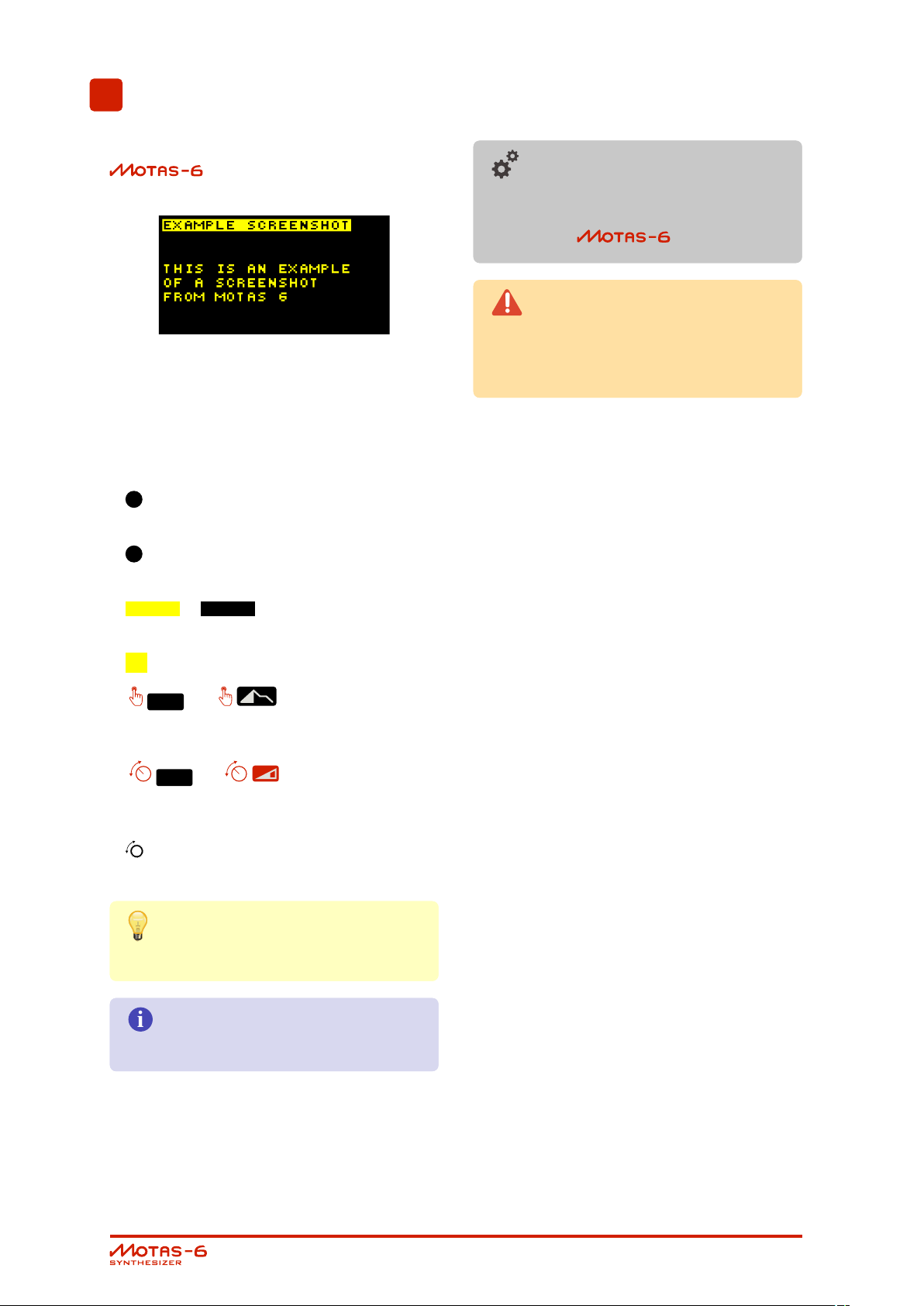
Document conventions
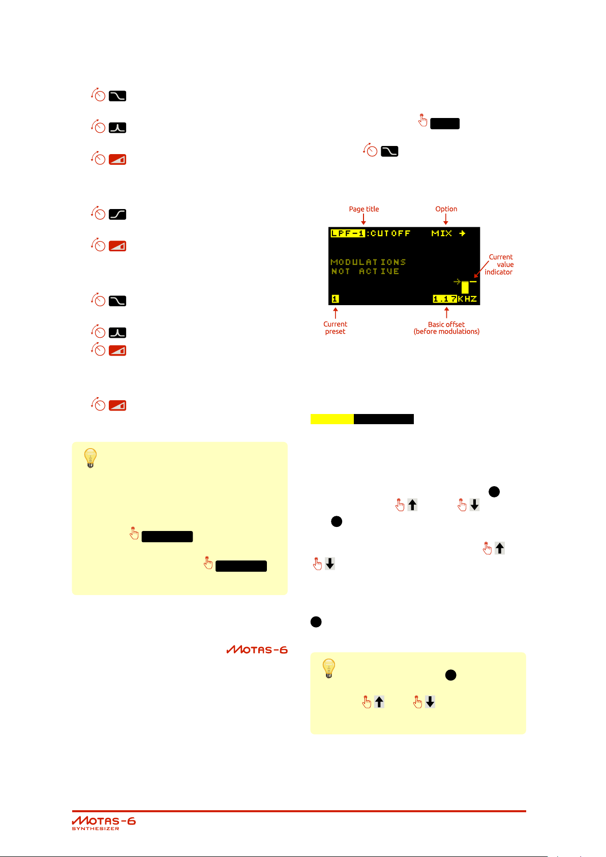
You will find many screenshots taken from
throughout this guide. An example
is show below:
The following document formatting conventions
are used:
• Link (blue text) is a weblink or a link to another
part of this document.
•1(number) refers to an item on the top panel
of the unit.
Advanced information section high-
lighted with a ’gears’ icon. It is not neces-
sary to understand these sections to suc-
cessfully use .
Warning section highlighted with a
’warning’ icon. It is important to ensure
that you read and understand these sec-
tions.
•A(letter) refers to an item on the rear panel of
the unit.
• this or this shows text you may see on
the display.
• I shows a symbol you may see on the display.
TE XT
•
on the top panel labelled with that text or sym-
bol.
•
on the top panel labelled with that text or sym-
bol.
• refers to the rotary encoder data-entry wheel
on the lower RHS of the front panel.
bulb’ icon.
or refers to a push button
TE XT
or refers to a rotary knob
Tip section highlighted with a ’light-
Information section highlighted with
an ’i’ icon.
User Guide v1.17
page 4

4
Introduction
is a super-flexible monophonic syn-
thesizer with classic analogue subtractive synthe-
sis and powerful digital control - giving huge mod-
ulation possibilities.
• Fully analogue audio signal path
• Three analogue oscillators (VCOs) with freely
mixable waveforms:
– triangle (oscillators 1, 2 and 3)
– sawtooth (oscillators 1, 2 and 3)
– variable width pulse (oscillators 1 and 3)
– square and sub-oscillator (oscillator 2)
• Oscillator hard-syncing (multiple options)
• Analogue phase modulation (oscillators 2 and
3)
• Analogue noise souce (white or pink)
• Internal audio feedback or external audio in-
put
• 4 CV/gate inputs for analogue control
• Three independent analogue filters (VCFs) with
flexible routing:
– Low-pass resonant filter (6-pole with selectable
outputs and resonance character adjustment)
– Second low-pass resonant filter (4-pole)
– High-pass filter (2-pole)
• Multiple output distortion options
• Powerful modulation architecture:
– 4 global LFOs (Low Frequency Oscillators)
– 4 global EGs (Envelope Generators)
– 33 parameter-local LFOs
– 33 parameter-local EGs
– Four freely configurable modulation
sources from MIDI and CV/gate inputs
• Quick-access buttons to 5 active patches
• Copy/reset/randomise feature
• Full MIDI control and USB MIDI interface
• Oscilloscope and spectrum analyser
• Built-in pattern sequencer
• Non-volatile internal memory for saving 500 patches,
56 patterns, 16 sequences and user settings
• High-resolution OLED graphic display
• Compact high-quality tabletop case
Analogue oscillators
has three analogue voltage-con-
trolled oscillators (VCOs) with various hard-sync,
pulse-width and phase-modulation options. These
are true analogue oscillators and not DCOs. The
oscillators, analogue noise source (with white/pink
output option) and an internal feedback routing
or external audio input all feed into a mixer be-
fore the filters.
Analogue filters
has very powerful filtering capabil-
ities. There is a 6-pole voltage-controlled low-pass
filter (VCF) with adjustable resonance to self-oscillation
(with selectable 1, 2, 3, 4, 5 and 6-pole outputs),
a 2-pole high-pass filter and a second 4-pole low-
pass filter with adjustable resonance to self-oscillation
(similar in design to the filter from a certain silver
box from the 1980s. . .)
The filters can be chained in parallel or in series
and the outputs are separately mixable giving huge
sound-creation potential. The final audio output
has a variety of clipping distortion options.
Modulation
Each analogue-controlled parameter has its own
dedicated LFO and EG. In addition each param-
eter has dedicated modulation amount settings
from velocity, pitch, the global modulation sources
and the global LFOs and EGs. Secondary ’mod-
ulation of the modulators’ is also possible, for ex-
ample, a global modulation source can control
the LFO frequency. This allows very flexible and
powerful control of the analogue sound.
Up to four global modulation sources can be freely
defined from incoming MIDI controller data and/or
analogue signals on the CV/gate inputs.
• Flexible arpeggiator
User Guide v1.17
page 5
The internal architecture uses high-
resolution digital signals for the modulation
allowing a total of 37 simultaneous LFOs
and EGs.
be adjusted for pitch, velocity, time, duration, micro-
tune and patch change. Real-time sound pa-
rameter changes can be recorded and edited
too. Patterns can be arranged into a 2-line simple
sequence with pattern repeat, transpose, time
offset and patch settings.
User interface
Dedicated analogue rotary potentiometers are
used to access the basic analogue parameter
pages and to allow fast ’tweaking’ in real-time.
In addition uses a rotary rotary en-
coder in combination with tactile push but-
tons for data entry and editing.
Display
has an OLED (organic light emitting
diode) display with a fast update rate and wide
viewing angle. The display intensity can be ad-
justed.
External connections
has traditional MIDI input and MIDI
output connectors in addition to USB MIDI. USB
MIDI allows faster data transfer to and from a PC
and is recognised as a standard
MIDI device (no special drivers should be needed).
More than 500 sound patches can be saved to
non-volatile memory.
There is a useful oscilloscope and spectrum anal-
yser feature that allow the user to study the out-
put signals on the display.
There are four independent analogue CV/gate
inputs to allow playing/modulation from external
analogue sequencers, controllers and modular
synthesizers.
The main audio output is monophonic and in ad-
dition there is a mono headphone output (on a
stereo connector).
Other features
has a flexible arpeggiator. There
are global and patch-specific arpeggiator set-
tings. The play mode, octave range, pattern, note
length and swing can be adjusted and synced to
MIDI, CV or internal clock. A special global mode
allows rapid patch changing as the arpeggiator
plays.
The pattern sequencer allows 1-bar patterns to
be entered where each note in each pattern can
User Guide v1.17
CHAPTER 4. INTRODUCTION page 6
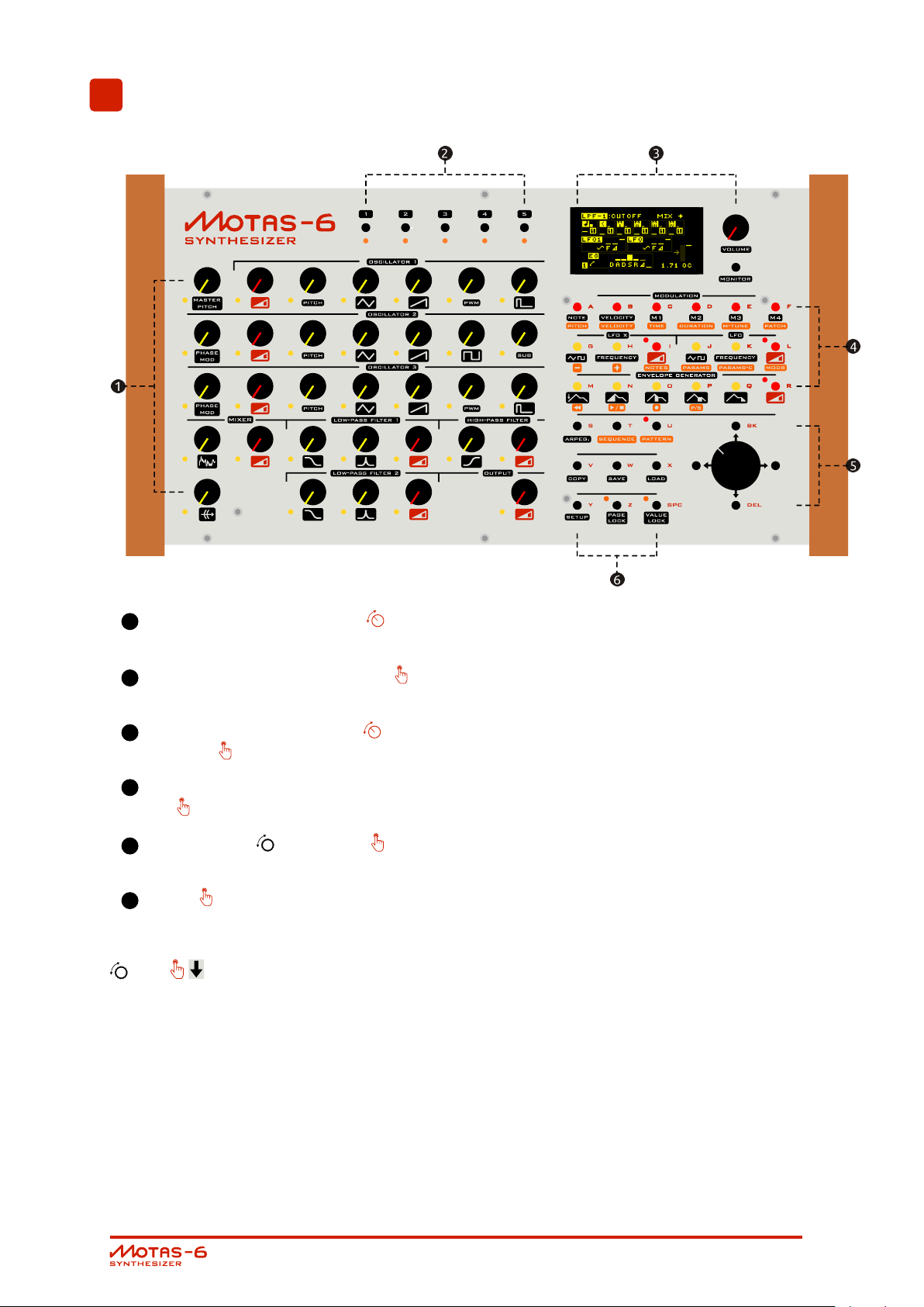
5
Top panel
1
sound editing ’parameter’ knobs with LEDs
[x 33]
2
quick-access patch-change buttons with
LEDs [x 5]
3
OLED display, main volume knob and mon-
itor button
4
modulation settings / sequence control but-
tons [x 18]
5
rotary encoder and buttons [x 4] for
data entry/options
6
buttons to access other features [x 9]
†
† Panic combination: pressing the rotary encoder
and simultaneously will turn off all play-
ing notes and reset controllers. Useful if, for exam-
ple, a controller keyboard is unplugged leaving
notes hanging.
User Guide v1.17
page 7
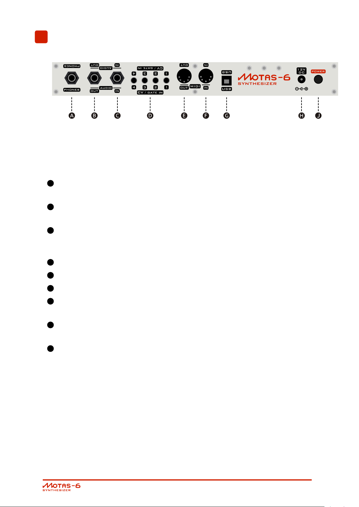
6
Rear panel
The lettering at the top of the rear panel is printed
upside down so that the user can read the letter-
ing when peering over from the top of the unit.
A
headphones out (2 channel mono)
[ Stereo 6.35mm phone socket ]
B
main audio out (mono)
[ Mono 6.35mm phone socket ]
C
external audio input (leave unconnected for
internal feedback routing)
[ Mono 6.35mm phone socket ]
D
CV/gate inputs [ 3.5mm sockets x4]
E
MIDI out [ 5-pin DIN socket ]
F
MIDI in [ 5-pin DIN socket ]
G
USB MIDI socket for connection to PC
[ USB type-B ]
H
power supply in
[ 2.1mm. 12V DC, centre positive ]
J
power on/off push switch
[ button in = power on ]
User Guide v1.17
page 8
7
Quick-start
1. Firstly ensure that the power buttonJis off
and the main volume control3is set to min-
imum.
2. Plug a MIDI cable from your MIDI keyboard
to the MIDI IN connectorF. Turn on your
MIDI keyboard and set it up to send MIDI
notes as you play.
Alternatively connect to your
PC with a USB cable – it should appear as a
standard MIDI device (once powered on).
Use your sequencer or other software to send
note data.
Ensure the receive MIDI chan-
nel matches the send channel number – for
more info see 18.3.
3. Plug a mono audio patch cable from the
main audio outBto your external amplifi-
cation system. Set the gain level low initially,
to avoid any audio pops when
is switched on. Alternatively monitor on head-
phonesA.
through the available presets sounds (in bank
0). As each preset is selected the settings
are loaded in and you should be able to
hear audio as you play. For more informa-
tion on loading sounds see chapter 13. Ad-
just the volume level control3to a suitable
listening level.
4. Plug in the 12V DC power supply into con-
nectionH.
5. Turn on using the power but-
tonJ. The display will show the start-up im-
age.
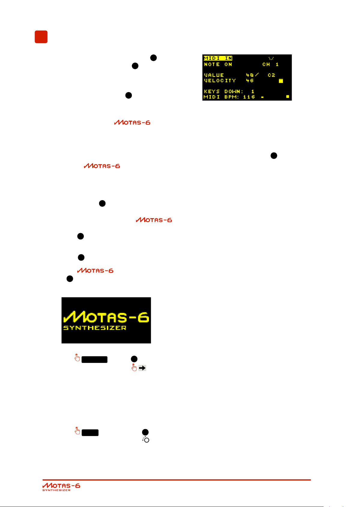
6. Press
then the right arrow button . The dis-
play will change and show MIDI diagnosics
monitoring information for the incoming MIDI
data if everything is working correctly. If you
don’t see this check your connections and
external settings. For more information on
the MIDI monitoring see chapter 14.
MO NI TOR
(in the3group) and
7. Press
and then use the rotary encoder to scroll
LOA D
User Guide v1.17
(button in the6group).
page 9

8
Control Overview
To access the settings (also known as parameters)
that determine the sound you turn a rotary knob
1
corresponding to the setting that you want
to change. Each rotary knob
1
is associated
with it’s own ’parameter page’. Normally the dis-
play will then change to show the settings for the
parameter page associated with that knob.
Turning a rotary knob
1
normally has the side-
effect of also changing the offset value for that
parameter page. Use the ’value lock’ feature
to allow changing of the active parameter page
without changing the offset. Press the
VALU E LOC K
button to toggle ’value-lock’ on
and off. When ’locked’ the LED will flash next to
the
VALU E LOC K
button.
Conversely use the ’page-lock’ mode to allow
rapid hands-on changes of parameter basic off-
sets such as sweeping filter cut-off, changing os-
cillator mix levels etc. without changing the ac-
tive parameter page. Press the
PAGE LOC K
button to toggle ’page-lock’ on and off. When
’locked’ the LED will flash next to the
PAGE LOC K
button.
For faster data entry when using the rotary en-
coder , push the rotary encoder wheel down
at the same time as turning.
MIDI panic
In the case of any ’stuck’ notes e.g. if a MIDI key-
board is unplugged whilst a note is ’on’, press and
hold the rotary encoder
wheel down and then
also press to turn all notes off.
Master volume
Turn the
VOL UME
to set the output volume
level.
Patch parameter editing
The sound generated by is controlled
by the settings on 33 parameter ’pages’ – each
parameter has its own ’page’ shown on the dis-
play. These are explained in detail in chapter 11.
To access a particular parameter page turn the
appropriate rotary knob
1
. The active pa-
rameter page is shown by the adjacent flashing
LED.
Patch changing
has 5 patches (sound setups) in
memory ready for easy access. To change pre-
sets press one of the preset2buttons
2
3
,
4
,
or
5
1
. The cor-
responding preset2LED will be lit to show the
active patch. See chapter 12 for more details.
Load/save/copy
To load or save patches, patterns or sequences
press
LOA D
or
SAVE
. To copy patch set-
tings, reset settings or randomise parameter page
settings press
CO PY
. See chapter 13 for more
details.
Monitor
To view signal level, the incoming MIDI signals and
output signals and access the oscilloscope and
spectrum analyser features use the ’monitor’ fea-
ture
MO NI TOR
. See chapter 14 for more details.
Arpeggiator
has a powerful arpeggiator feature
– press
AR PE G.
. See chapter 15 for more de-
tails.
Pattern sequence
has a pattern sequencer. Press
PATT ER N
SE QU ENC E
to access the patterns and
to access the sequencer. See
chapter 16 for more details.
Vector morphing
has a vector morphing feature to
allow smooth transition from the sound parame-
ters of one patch to another using an external
controller. To access the vector morphing feature
press whilst a preset page is displayed.
See chapter 17 for more details.
,
User Guide v1.17
page 10

Setup
To access various global settings and parameters
(such as MIDI receive channel, calibration and
modulation sources) press
SE TU P
. See chap-
ter 18 for more details.
Live sound changes
can send and receive MIDI NRPN
messages to allow external recording and con-
trol of patch settings. See chapter 19 for more
details.
User Guide v1.17
CHAPTER 8. CONTROL OVERVIEW page 11
9
Parameter pages
The sound generated by is controlled
by the settings on 33 parameter ’pages’ – each
parameter has its own ’page’ shown on the dis-
play. These are listed below and explained in de-
tail in chapter 11. To access a particular parame-
ter page turn the appropriate rotary knob
1
.
The active parameter page is shown by the adja-
cent flashing LED indicator.
Use the ’value lock’ feature to allow
changing of the active parameter page
without changing the sound parameters.
Press the
VALU E LOC K
button to toggle
’value-lock’ on and off. When ’locked’ the
LED will flash next to the
VALU E LOC K
button.
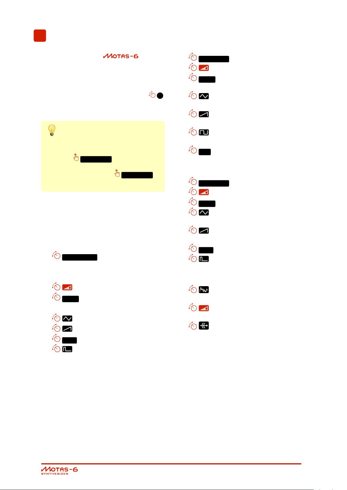
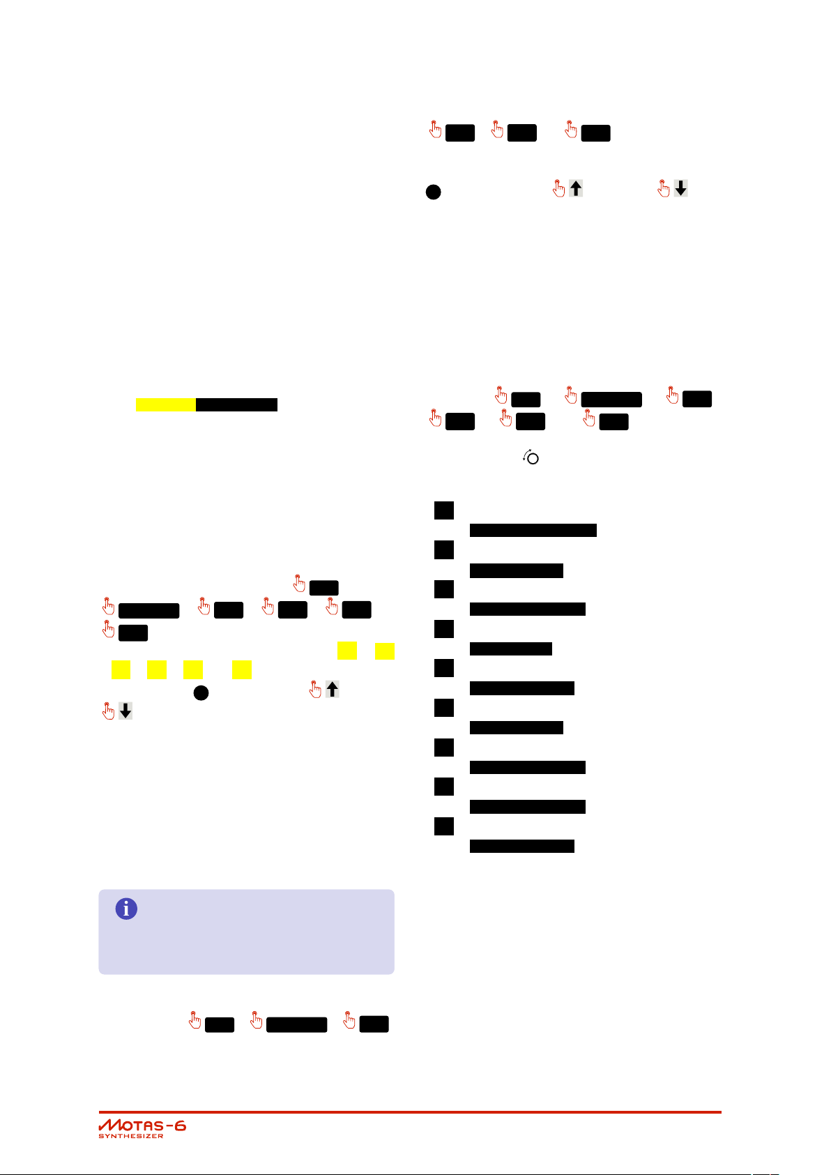
The listing below is a summary of each parameter
page starting from the top left of the front panel
moving from left-to-right and then down in rows.
PH AS E MOD
PI TC H
SU B
• Oscillator 3 pages:
PH AS E MOD
PI TC H
phase modulation control
overall volume level
pitch control and
hard sync. options
triangle waveform
volume level
sawtooth waveform
volume level
square waveform
volume level
sub-oscillator waveform
volume level
phase modulation control
overall volume level
pitch control
triangle waveform
volume level
Parameter page summary
• Master pitch page:
MA ST ER PITCH
• Oscillator 1 pages:
overall volume level
PI TC H
pitch control and
hard sync. options
triangle waveform volume level
sawtooth waveform volume level
PW M
pulse-width control
pulse waveform volume level
pitch control of all
3 oscillators
PW M
• Mixer pages:
sawtooth waveform
volume level
pulse-width control
pulse waveform
volume level
noise source volume level
and white/pink option
overall volume level from mixer
and boost option
feedback/external audio
input volume level
• Oscillator 2 pages:
User Guide v1.17
• Low-pass filter 1 pages:
page 12
cut-off frequency and
input routing options
resonance amount and
character option
output volume level and
routing options
• High-pass filter pages:
cut-off frequency and
input routing options
output volume level and
routing options
• Low-pass filter 2 pages:
cut-off frequency and
input routing options
resonance amount
So let’s start by explaining operation of one of
the parameter pages. Start by reseting the cur-
rent patch by pressing
CO PY
and selecting
’reset patch’. Then turn the low-pass filter 1 cut-
off control to access that parameter
page. You should now see something similar on
the display to that shown in the figure below.
output volume level and
routing options
• Output stage page:
output volume level and
clipping options
Use the ’page-lock’ mode to al-
low rapid hands-on changes of parame-
ter basic offsets such as sweeping filter cut-
off, changing oscillator mix levels etc. with-
out changing the active parameter page.
Press the
PAGE LOC K
button to toggle
’page-lock’ on and off. When ’locked’ the
LED will flash next to the
PAGE LOC K
button.
9.1 Parameter page display overview
Although controlling the sound in
may appear to be rather daunting at first given
the number of parameter pages and the large
number options on each page, once you have
mastered operation of one of the parameter pages
you will understand most of all the others as the
basic operation is common to all pages.
Page title
Each page has a ’destination’ i.e. what aspect
of the synthesizer it controls, and this is labelled at
the top left of the display. In this case it is
lpf-1 :cutoff - the cut-off frequency of
low-pass filter 1.
Basic offset
Each parameter page has a basic offset level that
can be adjusted using the rotary knobs1or ro-
tary encoder and up and down but-
tons5. All of the modulation sources (see chap-
ter 10) add (or subtract) from this offset to gener-
ate the final level. The rotary encoder, and
adjust the basic offset for the active page
only when the basic offset is the active editable
item (shown as flashing), otherwise they will con-
trol other parameters. However, the rotary knobs
1
always control the basic offset for their param-
eter page (except when ’value-lock’ is enabled).
Use the rotary knobs1for smooth
fine control of the parameter page offset.
Use the and buttons to jump
set amounts in offset.
User Guide v1.17
CHAPTER 9. PARAMETER PAGES page 13
Push the rotary encoder and turn
i
i
at the same time to change values in
larger steps for rapid sound adjustments.
Page options
Some parameter pages have additional options.
For pages with a single option and
cycle back and forth through the single option
settings. For pages with two options the
button cycles through option 1 whilst the
button cycles through option 2.
In the example shown the single option is for the
source of the audio input to the filter, in this case
set to the main mix. You can only change the
page option when the active editing item is the
basic offet (shown by flashing value at the bot-
tom right-hand of the display) otherwise
control other parameters (more on this later!).
The current value bar tries to follow
the parameter page value in real-time.
However, if the modulation is very fast this
display will not be able to ’keep-up’ and
so you will only see a snapshot of the value
at that point in time.
Current preset
has 5 preset patches. The current
patch for editing is shown as a number in the bot-
tom left corner (patch 1 in this case). In addi-
tion a corresponding preset2LED will be brightly
lit. When the arpeggiator or pattern sequencer
changes the played preset patch the LED for that
preset will be dimly lit, whilst the patch for editing
will still be brightly lit. To change presets press one
of the preset2buttons.
Current values
At the far right of the screen a horizontal bar shows
the current level of the destination signal in real
time. The current value is the sum of the basic
offset for the page with all the modulation signals
(see chapter 10 for explanation of the modula-
tion options).
If the controlling signal rises above the maximum
of the destination then an ’up’ arrow k is shown
instead of the bar, and if the controlling signal falls
below the minimum a ’down’ arrow l is shown
instead of the bar.
The horizontal arrow next to the solid vertical bar
shows the current position of the rotary knob
1
.
When the parameter page displays
modulations not active
the current value will follow the basic off-
set, since all the modulations amounts are
set to zero.
User Guide v1.17
CHAPTER 9. PARAMETER PAGES page 14
10
i
i
i
Modulation
Modulation means changing parameter values
from a modulation source. This could be a freely-
changing modulation with time, such as from a
low-frequency oscillator (LFO) that is not synchro-
nised or modulation that is synchronised to the
start of a key press, such as from an envelope
generator (EG) triggered by a note-on event.
Conventional analogue synthesizers typically have
a small number of LFOs (from 1 to 3 or so) and
EGs (usually 1 or 2) that are used for modulation.
In some cases the modulation sources have fixed
destinations (such as a dedicated EG for output
level) or can be set to only a limited number of
destinations (such as filter cut-off frequency or pitch).
is different – every parameter has
its own dedicated LFO and dedicated EG in ad-
dition to dedicated modulation amount settings
from velocity, pitch, 4 global LFOs, 4 global EGs
and 4 external modulation sources (MIDI or CV in-
put)! This powerful architecture allows complete
freedom to modulate and control almost every
aspect of the sound generation. You can freely
set the modulation for every parameter separately
if desired or have coupled modulation between
parameters using the global modulation sources,
if you wish.
Each parameter page allows you to set the lev-
els and routings of the various parameters that
determine the sound, but things get a lot more
interesting once some modulation is used. Mod-
ulation allows creation of interesting sounds that
change in character over time.
Each and every parameter page has dedicated
modulation control amounts from 9 sources:
I MIDI/CV note-on value
K MIDI note velocity
G MIDI/CV global modulation M1
H MIDI/CV global modulation M2
I MIDI/CV global modulation M3
J MIDI/CV global modulation M4
lfox choice of global LFO x = 1–4
lfo dedicated LFO for
each parameter page
egx choice of global EG x = 1 – 4, or
dedicated EG
The modulation amount can be zero (for no mod-
ulation), positive or negative. The actual modula-
tion signal applied to the parameter page value
is the product (i.e. multiplication) of the mod-
ulation amount and the modulation source sig-
nal at that point in time. All of the modulation
signals are added together with the parameter
page basic offset value to give the resulting value
for the parameter page value.
The modulation signals are ’bipo-
lar’ – this means that when the source is
at its middle value the modulation effect
will be zero. For a positive modulation
amount when the source is at its positive
peak the modulation will increase the pa-
rameter page value and when the source
is at its negative peak the modulation will
decrease the parameter page value.
Perhaps the most common ’modu-
lation’ used in synthesizing sounds (and of-
ten not really considered as modulation)
is simply applying an envelope modula-
tion to the output signal level. With this
’modulation’ the volume increases once
a key is pressed and decays away once
the key is released. Without this modula-
tion a constant sound volume would be
heard whether or not a key was pressed.
User Guide v1.17
shows the modulation peak-to-peak max-
imum change. For example, if the mod-
ulation amount for LFO on the oscillator 1
pitch parameter page is set to 12.00 s then
the modulation of the pitch will vary over
12 semitones (1 octave) as the LFO wave-
form cycles from it’s minimum to maximum
values.
The modulation amount displayed
page 15
10.1 MIDI / CV Modulations
i
There are 6 possible MIDI / CV modulation sources:
MIDI note-on value (or CV pitch), MIDI velocity (or
CV velocity) and 4 globally assigned MIDI or CV
modulation sources.
The interface for all these modulations is the same.
Each source has it’s own icon on the display run-
ning along the second row.
Each modulation source has two amount settings.
The first (primary) sets the amount of the modu-
lation signal to add or subtract to the parame-
ter page basic offset e.g if set on the parameter
page lpf-1 :cutoff it would directly in-
crease or decrease the cut-off frequency of low-
pass filter 1 as the modulation signal increases or
decreases.
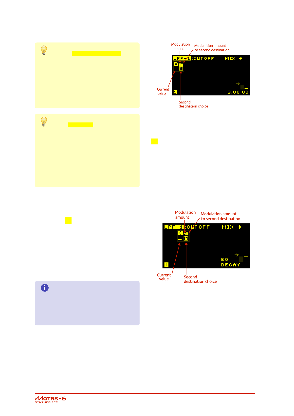
It is also possible to modulate the modulations!
This is where the secondary destination and sec-
ondary amount is used.
From a patch parameter page press the modu-
M2
KE Y
,
,
M3
or
lation button desired once (i.e.
VE LO CIT Y
M4
). The modulation icon flashes to show
M1
,
,
it is in primary edit mode (i.e. one of I , K
, G , H , I or J flashes). Now turn the
rotary encoder5or push the up or down
buttons - the amount of this modulation
source applied to the parameter page (the pri-
mary destination) is
shown as a small vertical bar on the left-hand side
above the modulation icon. Set positive values
to increase the parameter page basic offset with
increasing modulation signal or set negative val-
ues to decrease the parameter page basic offset
with increasing modulation signal.
Positive modulation amounts are
shown by a solid bar whilst negative
amounts are shown with a hollow bar.
M2
M3
,
or
M4
again). The mod-
ulation icon flashes together with the secondary
destination icon. Now turn the rotary encoder
5
or push the up or down but-
tons - this sets the amount this modulation source
has on the secondary destination. The amount
is shown as a small vertical bar on the right-hand
side above the modulation icon. Set positive val-
ues to increase the destination level with increas-
ing modulation signal or set negative values to
decrease the destination level with increasing mod-
ulation signal.
Now press the modulation button a third time (i.e.
press the
M2
KE Y
M3
,
,
or
VE LO CIT Y
M4
M1
,
again). Only
,
the secondary destination icon flashes. Now the
rotary encoder controls the secondary desti-
nation from one of the following nine options:
M selected global LFO 1–4 amount
lfox amount
N dedicated LFO frequency
lfo freq
O dedicated LFO amount
lfo amount
P dedicated EG rate
eg rate
Q dedicated EG attack
eg attack
R dedicated EG decay
eg decay
S dedicated EG sustain
eg sustain
T dedicated EG release
eg release
U dedicated EG amount
eg amount
Pressing the modulation button a fourth time re-
turns editing to the parameter page basic offset.
Details of each modulation source is given in the
subsections below.
Now press the modulation button a second time
(i.e. press the
KE Y
User Guide v1.17
,
VE LO CIT Y
M1
,
,
CHAPTER 10. MODULATION page 16
On the master pitch pa-
i
rameter page set a secondary destina-
tion of LFO amount (and set an appropri-
ate secondary level amount) for a global
modulation source which is assigned to
the MIDI modulation wheel. Now the MIDI
modulation wheel will control the depth of
vibrato effect of the LFO.
On the output parameter page
set a secondary destination of EG rate
(and an appropriate secondary level
amount) for the MIDI note modulation
source. Set the output page to use the
unique EG. Now higher pitch notes will
have an EG envelope which processes
faster such as is common for real-world
stringed instruments.
Note pitch modulation
On row 2 of the display, starting at the left-hand
side is shown the note modulation setting, indicated by the I symbol. This controls how much
the MIDI note-on signals or CV pitch voltage af-
fect the page’s destination (which in the exam-
ple shown below is the LPF-1 cut-off frequency) or
how note-on signals affect other modulations for
this page (if the secondary destination is used).
Velocity modulation
To the right of the note modulation setting is shown
the velocity modulation setting indicated by the
K symbol. This section controls how MIDI note
velocity signals affect the page’s destination and
levels or setttings of other modulators for this page,
in exactly the same way as for the note-on mod-
ulation.
The note-on MIDI velocity is the source of this mod-
ulation signal. The harder the key is struck (on a
touch sensitive MIDI keyboard) the higher this sig-
nal.
The higher the incoming MIDI note-on pitch or CV
pitch voltage the higher the modulation signal.
The note pitch modulation signal
is derived from the ’latest’ (i.e. most re-
cent) note currently being played, includ-
ing the effects of portamento, but exclud-
ing pitch-bend signals.
User Guide v1.17
CHAPTER 10. MODULATION page 17
Modulation sources M1, M2, M3 and M4
Each of these separate modulation sources can
be assigned to any MIDI controller code e.g. mod-
ulation wheel, breath control, volume. . . or even
pitch bend. Alternatively the modulation signals
can come from the analogue CV/gate signal in-
puts. The source is stored with the patch but can
be overridden by a global modulation source set-
ting. See section 18.4 for how to setup these global
modulation sources.
 Loading...