

Page 1
KÖBER LTD DUMBRAVA ROSIE - VADURI BRANCH OFFICE
Branch Office:Vaduri, No. 280, Alexandru cel Bun, Neamt District, Postal Code 617511, Romania
Phone : +40.233.24.17.46, 233.24.19.33, Fax : +40.233.24.19.29
E-mail : , www.motan.rooffi[email protected]
TECHNICAL INSTRUCTIONS
FOR INSTALLATION/ USAGE/ MAINTENANCE
Köber LTD
Vaduri Branch Office
1798
OPTIMUS MT
C15SPV 24MEFM
Page 2

CONTENTS
General presentationof the wall hung gasboiler
Connection for evacuation of theflue gases ...............................................................
Operating mode
.................................................................................
..........................................................
....................................................
General description of the wallhung gas boiler ...........................................................
Description of the boilers types..................................................................................
Symbols ....................................................................................................................
General instructions concerning the safetyof the wall hung gas boiler ........................
Technical characteristics...........................................................................................
Functional and constructive characteristics ..............................................................
Constitutive elements of wall hung gas boiler.............................................................
The heat generator ...................................................................................................
The exhaust gases/water heat exchanger.................................................................
The heating and domestic hotwater circuits Hydrauliccircuits ..................................
The command and control system ............................................................................
The external shell ......................................................................................................
The hydraulic characteristic of circulationpump .........................................................
Mounting/installation instructions ..............................................................................
The location of the unit...............................................................................................
The central heating ...................................................................................................
The gas supply ..........................................................................................................
The electric power supply .........................................................................................
Instructions for the final user(beneficiary) ..................................................................
Operating instructions ..............................................................................................
The control panel .......................................................................................................
The LCD display board inthe user module .................................................................
The LCD display in theuser module ................................................
The pressure checking ..............................................................................................
Additional facilities that may beobtained by ...............................................................
Handing over to the beneficiary.................................................................................
Recommendations for the yearly checking ...............................................................
Marking, documents, packing, storage, transport, quality and warranty conditions .....
Marking ......................................................................................................................
Documents ................................................................................................................
Packing ......................................................................................................................
Storage .....................................................................................................................
Shipment ...................................................................................................................
Quality and warranty conditions .................................................................................
Responsibilities during the warranty period ...............................................................
Malfunctions which refer to themanufacturer's responsibility ....................................
Malfunctions which refer to theresponsibility of the utilities provider ...........................
Malfunctions for which the manufactureris not responsible .......................................
List and plans necessary formounting and putting into service ...................................
Plan 1 ........................................................................................................................
Plan 2 .........................................................................................................................
Plan 3 .........................................................................................................................
Plan 4 .........................................................................................................................
Plan 5 .........................................................................................................................
The domestic hot water module, The heating module, Antifrost function, Auto-checking
and safety functions, The boiler shutting down in safety conditions .....................................
The functioning of the heating unit
Other functions concerning the safety ofthe boiler
Pg
Pg
Pg.
Pg
Pg 4
Pg 5
Pg 5
Pg 6
Pg 6
Pg 7
Pg 7
Pg 8
Pg 8
Pg 9
Pg 10
Pg 10
Pg 10
Pg 11
Pg 11
Pg 12
Pg 13
Pg 13
Pg 13
Pg 13
Pg 13
Pg 15
Pg 16
Pg 17
Pg 17
Pg 18
Pg 19
Pg 19
Pg 20
Pg 20
Pg 20
Pg 20
Pg 20
Pg 20
Pg 20
Pg 21
Pg 21
Pg 22
Pg 22
Pg 23
Pg 23
Pg 24
Pg 25
Pg 26
Pg 27
. 3
. 3
3
. 3
.
.
.
.
.
.
.
.
.
.
.
.
.
.
.
.
.
.
.
.
.
.
.
.
.
.
.
.
.
.
.
.
.
.
.
.
.
.
.
.
.
.
.
.
.
Page 3

INTRODUCTION TO THE BOILER
General description of the boiler
The wall hung gas boiler is a fuel gas-consuming appliance which has the role of
turning the fuel gas power into thermal energy through burning.
This appliance runs unsupervised due to its protection and control systems.
The boiler is made of many parts that we are going to describe in the following
chapters.
The gas enters inside the boiler through the gas feeding circuit made ofa coupling
and a reducing valve which will be set at 20 mbar for G20 A(L) and A(H) subgroups.
The reducing valve will be set at 37 mbar for LPG (propane subgroups and propanebutane mixtures). Thus it gets into the gas valve which has the role of controlling the
gas discharge at the outlet to the burner.
The ignition achieves by flame activating by an ignition electrode, by means of
an ignition transformer.
During the combustion, the flame sensing is made by an ionization sensor.
The boiler type with forced draft is provided with a fan which evacuates the
exhaust gases. In the initiation phase, this evacuates an air volume to provide an
unexplosive ignition. The explosive ignition may occur due to a gas storage from the
non-operating period.
The combustion chamber, as a plate parallelotope, interior ceramics fibre-lined,
is designed to allow the transfer to the exchanger with less heat leakages.
In case of the CH circuit of the two heat exchangers type, the heat resulted from
fuel gas ignition is taken over by the monothermal heat exchanger and sent to the
thermal agent (water) which is delivered by the circulating pump through the heating
installation. In case of on the DHW circuit, a water discharge is detected by the
flowmeter, the 3- way gas valve is energized. The 3- way gas valve achieves the
transition from the central heating circuit on the short circuit through the plate heat
exchanger (the main plate heat exchanger) and the heat transfer is realized by means
of this to the DHW circuit (the secondary plate heat exchanger).
The scavenging is realized by means of the fan.
The running protection andcontrol are performed electronically. The boiler setting
is made from the control board (see the chapter concerning this subject).
DESCRIPTION OF THE BOILER
3
BOILER
TYPE
C15 SPV 24 MEFM
Useful power
Accessories
[kcal/h] The fan The pump
The
expansion
vessel
DHW
instant
production
20670
X X X X
SYMBOLS
S- with instant production of DHW (without cumulation)
P- with pump
V-with closed expansion vessel
24-the maximum power output in kW
M- the burner is supplied by a continuous modulating valve
E- the ignition and the control of the flame are electronically-made
F-the forced scavenging
M-monothermal
OPTIMUS MT
Page 4
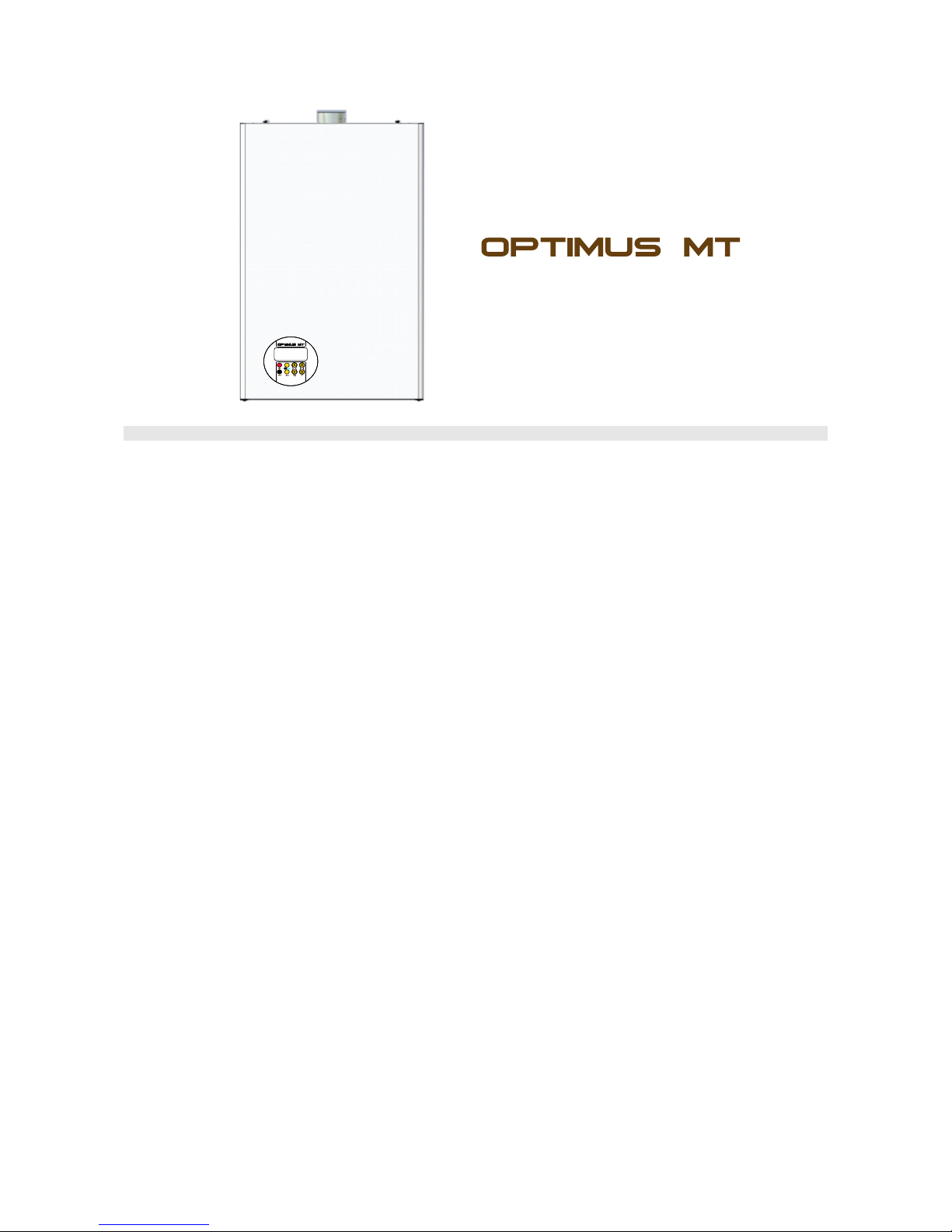
C 15 SPV 24 MEFM
GENERAL INSTRUCTIONS CONCERNING THE BOILER SAFETY
!
!
!
!
!
!
!
!
!
!
!
!
This manual is part of the product and it has tobe given to the user.
Read this manual carefully and keep it carefully for a further application by the user and by the
mounting and installing authorized personnel.
The installation, the putting into service, the service-repair operations and a periodical
technical checking are performed only by authorized personnel in accordance with the regulations
in force. All the indications of this manual must be respected; any exception may cause damages
and the producer isn`t responsible forthese.
In case of a defective running of the device, shut it down and call up immediately one of the
breakdown services units.
To guarantee the boiler efficiency and its correct running it is recommendable that the boiler be
checked yearly by the qualified personnel,complying with the manufacturer`s conditions.
If the device is sold or given, make sure it is delivered with its technical handbook in order to be
consulted by the new user/ installer.
In case of some components damaging there will be used only the original components. You
must have the manufacturer`s acceptance to use some components from another company, you
must obtain the writtenacceptanceof the producer sothat you may use those components.
This boiler will be used properly. Any other usewill be considered unsuitable.
There is excluded any contractual or extra-contractual responsibility of the producer for the
damages caused by the installing or usage errors and by thenon-observance of his instructions.
The maximum limit of the water hardness inlet is of maximum 5ºF (French degrees) on the
DHW circuit, equal to 50 mg CaCO2 or an equivalent quantity of other salts as Ca and Mg. It is
compulsory to install asoftener filter onthe domestic water circuit, a mechanical impurities filter (Y
filter) on the CH installation return and a pressure controller onthe gas supply circuit.
It is recommendable to use these boilers types presented in this manual to heat areas of 150
mp (at a mediumheight of 2,5 m of the heat volume).
Unsubmitting to these technical manual regulations as to the warranty certificate leads to
warranty loss.
4
RESETMOD
Page 5

Name
Type OPTIMUS MT - C 15 SPV 24 MEFM
Forced
Sealed
92,7%
93,7%
10 - 23,7 kw
10,9 - 25,49 kw
20 mbar
35 mbar
30 - 37 mbar
230 VAC, 50 Hz
160 W
40 kg
1 L
1,1- 2,6 Nm /h
0,4 - 1,07 kg/h
Draft
Combustion chamber
Efficiency at maximum load
Efficiency at minimum load
Useful power (min/ max)
Burner nominal load (min/ max)
Gas pressure
NG on coupling ( behind the reducer)
NG on maximum admitted output
LPG
Power-supply
Power consumption
Weight
Heat exchanger output
-
0,5 ºi 3 bar
40 - 80°C
3/4"
1/2"
3/4"
275
415
700
850
7 L
Central heating
Minimum and maximum admitted pressure
Temperature on the heating circuit
Connections - inlet outlet central heating
- inlet outlet DHW
- gas supply
Dimensions - depth (mm)
- Width (mm)
- Height (mm)
- With mounted elbow (mm)
Expansion vessel with membrane
NG consumption (8500 kcal/ Nm3)
At useful power (max/ min)
LPG consumption (20425 kcal/ kg)
At maximum output
3
5
TECHNICAL CHARACTERISTICS
CONSTRUCTIVE AND FUNCTIONAL CHARACTERISTICS
30 - 60°C
13,5 l/min
9,7 l/min
7,5l/min
DHW temperature range
Flow values
Ät °C=25
Ät °C=35
Ät °C=45
Page 6
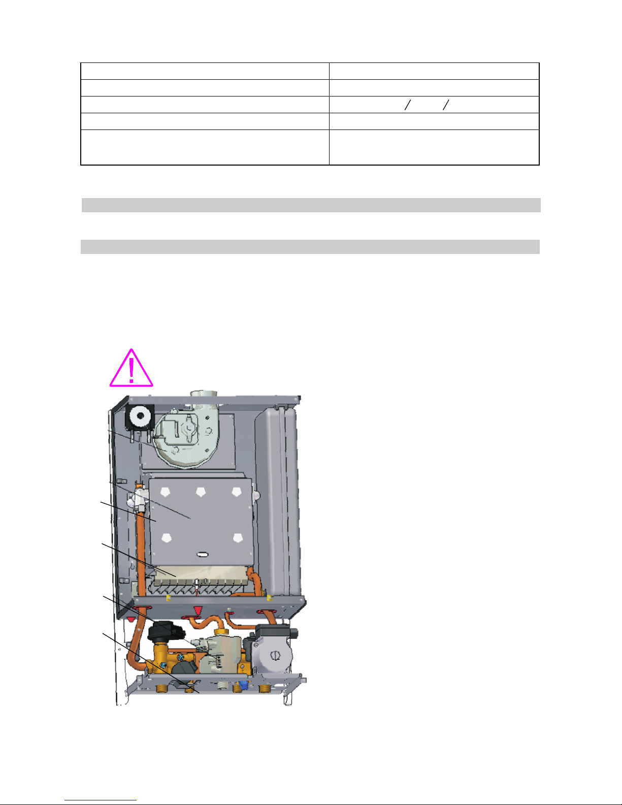
PRINCIPAL COMPONENTS OF THE BOILER
The heat generator
It is designed to supply the necessary heat for the heating exchange withthe heating and DHW
circuits. It is made of the following elements:
The gas feeding circuit will be performed through a reducing valve which will set the inlet
pressure at 20-25 mbar NG,respectively 30-37 mbar for LPG.
It is compulsory to mount a pressure controller on the gas
feeding circuit.
1. The gas valve
2. The burner
is designed to allow a
continuous modulation of combustion,
supplying the minimum, medium and
maximum gas pressures required by the
boiler running at the minimum, medium and
maximum load. The connector between the
gas valve and the burner is the copper pipe
(14x1).
is stainless-made, forced or
atmospherics, with 11 cannularinclines and it
runs with fuel gas (NG or LPG). The burner
output is set in a modulated systemby means
of a gas modulating valve so that it supply a
maximum useful power of 23,7 kW.
3. The combustion chamber is design to
allow the heat transfer to the heat exchanger
with less heat leakages. We chose a simple
constructive solution as a rectangular piping
of 170 mm between the burner and the heat
exchanger. To reduce the heat leakages, the
piping walls are isolated indoor with heat
insulating material (ceramics fibres).
4
3
2
1
Domestic cold water pressure
Exhaust gases temperature at rated output
Burned gases connection ( input- output)
Burned gases connection length
Orientative values
Maximum water content in the installation
Maximum surface of the precinct
0,2 - 8 bar
142,4°C
O 100 / O 60
Max 3 m
150 l
150 m²
6
Page 7
7
4
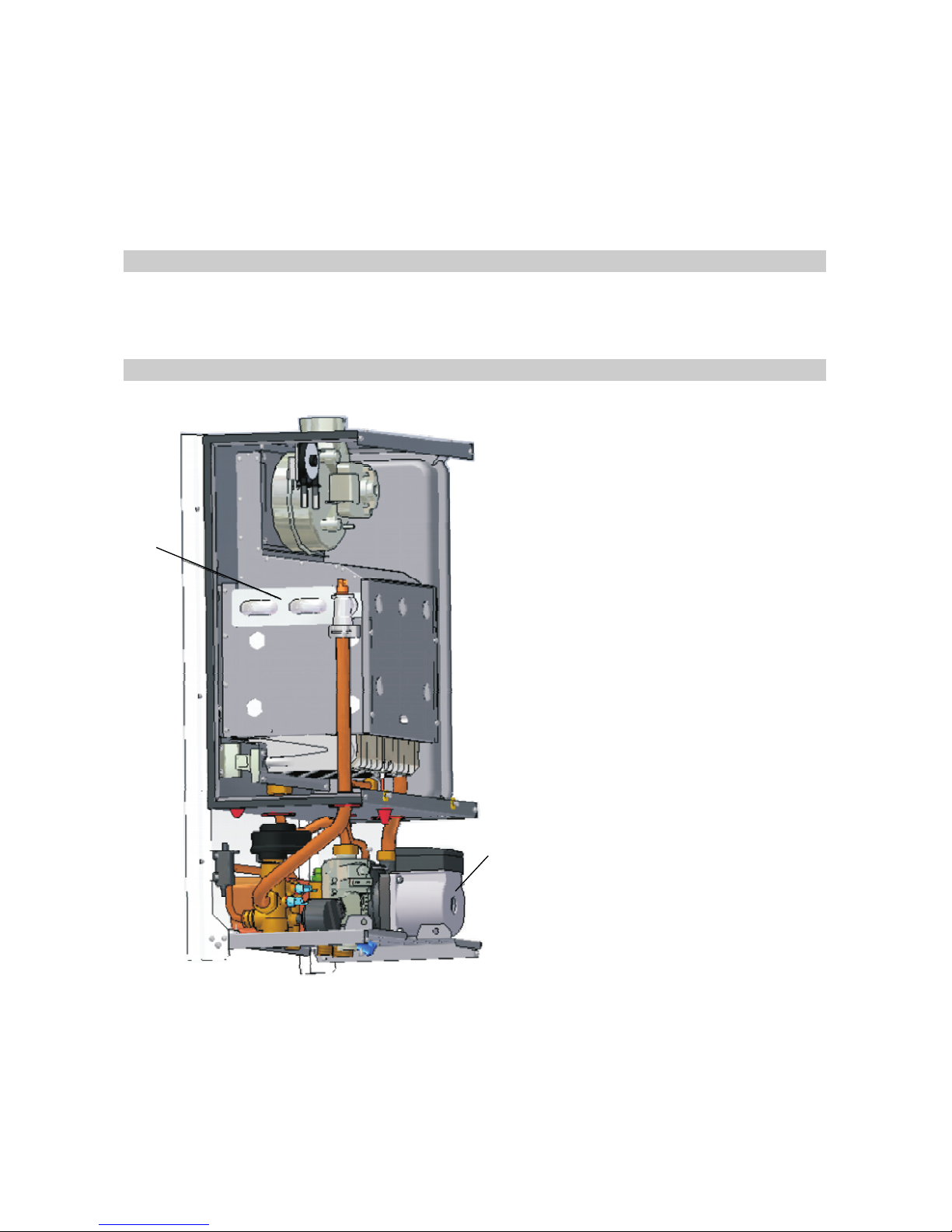
The boiler is provided with afan for scavenging.
The flue system and the air supply (for the boiler with forced draft) is made of two concentric
pipes connected to the outside of the room where the boileris mounted.
is monothermal, the domestic water is
heated through the plate heat exchanger.
From the power pointof viewthe rated output is of 24kW and the efficiency over 93%.
-
The fan
The exhaust gases/ water heat exchanger
The exhaust gases/ water heat exchanger
The heating and DHW circuits - Hydraulic circuits
- DHW circuit is with plateheat exchanger.
5
7
They are designed to allow thethermal
transfer to the external heating
and DHW installations.
- the loading circuit of the installation is
made of the valve and the copper pipe
connected to the domestic cold water
supply line;
- the relief valve of the circuit is designed
to reduce the pressure from the heating
circuit and to open at 3 bars full
pressure;
- the ventilation circuit of the installation
is made of an air-release valve which
allows the air discharge from the heating
circuit, mounted on the circulating pump
shell;
- The heating agent recirculating pump (7)
is designed to supply the output
necessary for the heating agent recycling
through the heating circuit;
- Expansion vessel is designed to allow
the expansion processes from the heat
installation, preventing from hydraulics
overstraining or damaging. This has a
capacity of 7 litres.
- The automatic by-pass circuit is made of
a copper pipe of 14x1 mm fixed between
the heating circuit turn and return and a
safety valve set to open at 0,3 bar to
allow the heat carrier recycling through
the heat exchanger and pump, in case of
some pressure differences,
between the external heat installation
turn and return at over 0,3 bar.
The heating circuit
Page 8
8
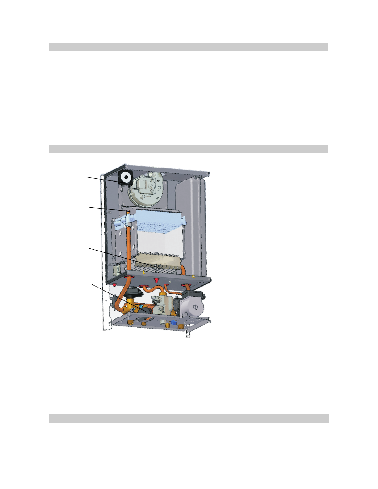
The command and control system of the boiler running performs:
The command and controlsystem is madeof thefollowing components:
- the ignition and the protection when the flame is extinguished, provided by the electronic
ignition;
- the protection when the gas is switched off, provided by electro-valve;
- the water pressure signalling in the boiler, provided by minimum pressure sensor;
- the temperature signalling on the heating and DHW circuits, provided by the electronic board
functions;
- the setting of the heating cycle following the instructions of the temperature control switch;
- the safety of the boiler against excessive temperature, provided by the safety thermostat at
overpressure, through the safety valve and at water leakages through the minimum pressure
switch from the circuit;
- protection against draft deficiency, by the fan derangement or the exhaust piping blockage of
the exhaust gases, provided by the combustion pressure switch .
- the electronic board
-
- heating circuit temperature
sensor
- DHW temperature sensor
- Flowmeter
- Ignition/ ionization electrode
as a
controller of the boiler running
(see the attached drawing).
the measuring and pilot cells
of the functional parameters for the
boiler
which sends the
temperature signal to the electronic
control block of the heating circuit.
which sends the temperature signal
to the electronic control block of the
DHW circuit.
as a detector of
the DHW consumption which sends
the DHW circuit running command
to the electronic control block.
(8) with double role, of combustion
flame activation and sensing.
- Air pressure switch (9)
- Temperature sensors
- Temperature switch (10)
- Programmer ambient sensor
- Water pressure sensor
The external shell
as a detector and controller of the exhaust gases, which
determines the heating and DHW circuits running.
as reading the temperature on the heating circuit (the electronic
board display).
as a detector and controller of the maximum temperature on the
heating circuit which sends the non-running command of the heating circuit in case a maximum
admitted temperature is exceeded.
as setting the ambient temperature from a room (optional).
as a detector of the minimum pressure on the heating circuit.
It has a parallelepipedal shape. It is detachable and electrostatically painted.
The shell covers the pressurized combustion chamber and the enclosed installations.
9
10
8
11
Page 9
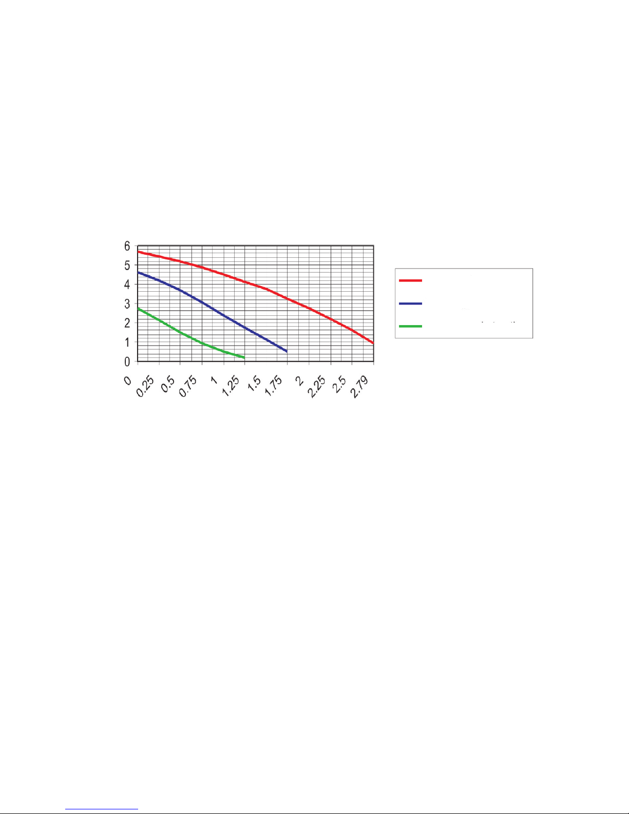
For designing the central heating installation we must be aware of the hydraulic features of the
pump.
9
The hydraulic characteristic of the pump
Pressure pump P[mca]
Pump output Q[mc/h]
the third stage of
the speed
the second stage
of the speed
the first stage of
the speed
Page 10

10
MOUNTING-INSTALLATION INSTRUCTIONS
The chapter addresses both to the qualified persons which contribute to the boiler installation
and to the beneficiary which is concerned that the effected works to be done following the
safety rules in operation of all the installations which contribute to the good running of the
boiler.
!
!
!
The boiler installation is not the same with the boiler
starting.
The boiler starting must be done by the authorized
personnel in accordance with the current legislation.
There is no guarantee without the authorized personnel
signing the putting into service statement, and the
company withdraws any boiler guarantee or running
responsibilities.
The boiler location
The central heating
In accordance with the current regulations: The norms for the designing and execution of the
NG supply systems, The norms for the NG supply systems utilization and The norms for the
designing and execution of the liquefied petroleum gas supply systems (LPG).
There are several conditions for installing the boilers:
-The appliances have the protection IP 40 level.
-The boiler may be installed in any room with an air humidity of maximum 60% between
20-30º C.
The heating system will be designed by the qualified and authorized personnel, in the
mounting/installing activities.
It is important to pay attention to the pipes dimensions, head losses and heating elements
while designing the heating system.
The installation filling up must bedone with softened water.
Couplings may be executed by gluing or compression fittings for the copper pipes, coupling
etc. The pipes must be provided with the necessary inclination for the ventilation and a light
evacuation to the adequate points fromthe installation.
Couplings and sockets
The evacuation. The evacuation points must be situated in the practicable places which allow
the water drainage from the heating circuit. It is recommendable that the minimum diameter should
be ½.
The ventilation. It is recommendable that the manual ventilators should be introduced on each
heating element (central heating). The water contains a certain quantity of resolved gases at the
first filling as well as thefurther water fillings of the heating system.
Once the system has been heated, the gases will be collected in the highest points of the
system whence they must discharged. The installation of some (manual or automatic) ventilators
will allow the evacuation both atthe first filling and during the running, in thesesystem points.
The filling. After the pipes connecting, the two circuits will be filled up with water gradually (the
boiler and the installation, respectively the coil from the DHW circuit) till the complete filling and it
should be checked so that thereare no leakages.
Page 11

11
!
!
!
You must not use the boiler empty or only partly filled with
water.
THE USE OF EMPTY OR PARTLY FILLED BOILER MAY
LEADS TO EXPLOSION.
The domestic cold water supply pipe of the DHW
processing circuit remains permanently open (the
closing of the net is made only by the valves from the
discharge points) to allow the dilatation taking over from
this circuit.
MOUNTING-INSTALLATION INSTRUCTIONS
The gas supply
The gas supply (NG or LPG) must be done in accordance with the standards.
* The minimum/maximum inlet pressure in the gas valve, in case of using the natural gas
must be between 25-30mbarstatic and between 20-25 mbar dynamic.
* The minimum/maximum inlet pressure in the gas valve, in case of using LPG, must be
between 30-50 mbar static and 25-45 mbar dynamic.
In case of notsubsuming tothese standards the combustion performanceswill lower.
On installing you mustknow the gas type that the boilerhas beenset for,to resetit correctly for
another gas type if it needs.
For exchanging the NG running forthe LPG running you mustfollow two operations:
* The setting from the electronic board which is performed by positioning the J6 jumper
(see the Electrical Diagram) on the two pines LPG module. (The J6 jumper is situated on a
single pine methane gas module).
* The mounting of the nozzles set of 0,77 mm diameter used for LPG running. (The
diameter of these nozzles is 1,3mm for methane gas).
The exchanging for NG is realized by performing the setting operations, from above, in the
reverse sense.
The setting will be performed by the producer following the beneficiary request or the service
authorized according to the current standards, operation which is performed on putting intoservice.
! You must install a pressure controller on the gas supply
circuit.
! The gas supply pipes must not have diameters smaller than
the boiler coupling.
Electric power supply
The boiler must be connected to a monophase net of 230 V-50 Hz with zero protection,
through the 5A fusible plugs. The colours semantics will be as follow: brown= phase, blue=null,
green-yellow= earthing.
The external connections must be according to the current standards. The connection to the
electrical network of the building must allow a complete electrical isolation of the boiler in case an
intervention must be done.
Page 12

12
!
!
You must not shut down the exhaust checking device, because
your life and healthwill bein danger.
Only the qualified personnel will do the replacement, according to
the current legislation andto theoriginal pieces used by the producer.
!It is obligatory to place the boilers in areas with ventilation
according to the current standards. The technical instructions
should be studied beforemounting/ installing, starting or servicing.
It`s forbbiden to install the boiler without earthing.
THE COUPLING FOR SCAVENGING
Without coupling to the chimney
The scavenging is made through a pipe of 60 mm diameter, coaxial with the air inlet
pipe of 100 mm diameter. The exhaust pipe is within the inlet one.
The input-output coaxial flue system is delivered with the boiler. It is made of an elbow,
input-output pipe and the necessary fittings.
Page 13
13
INSTRUCTIONS FOR THE FINAL USER (BENEFECIARY)
The control, protection and automation elements provide:
* The flame ignition
* The flame sensing
* The temperature and water signalling in the boiler
* The temperature regulation on the heating circuit
* The temperature regulation on the DHW circuit
* The pump starting at the heating water demand
* The safety of the boiler at overheating and overpressure
* Draft deficiency (air pressure switch)
* The boiler safety at minimum water level (water pressure switch)
* The DHW demand sensing (flowmeter) and giving priority to this discharge
The indicators and the operating buttons are placed on the control board.
The chronothermostat or the room thermostat may be installed on demand.
UTILIZATION INSTRUCTIONS
The control board
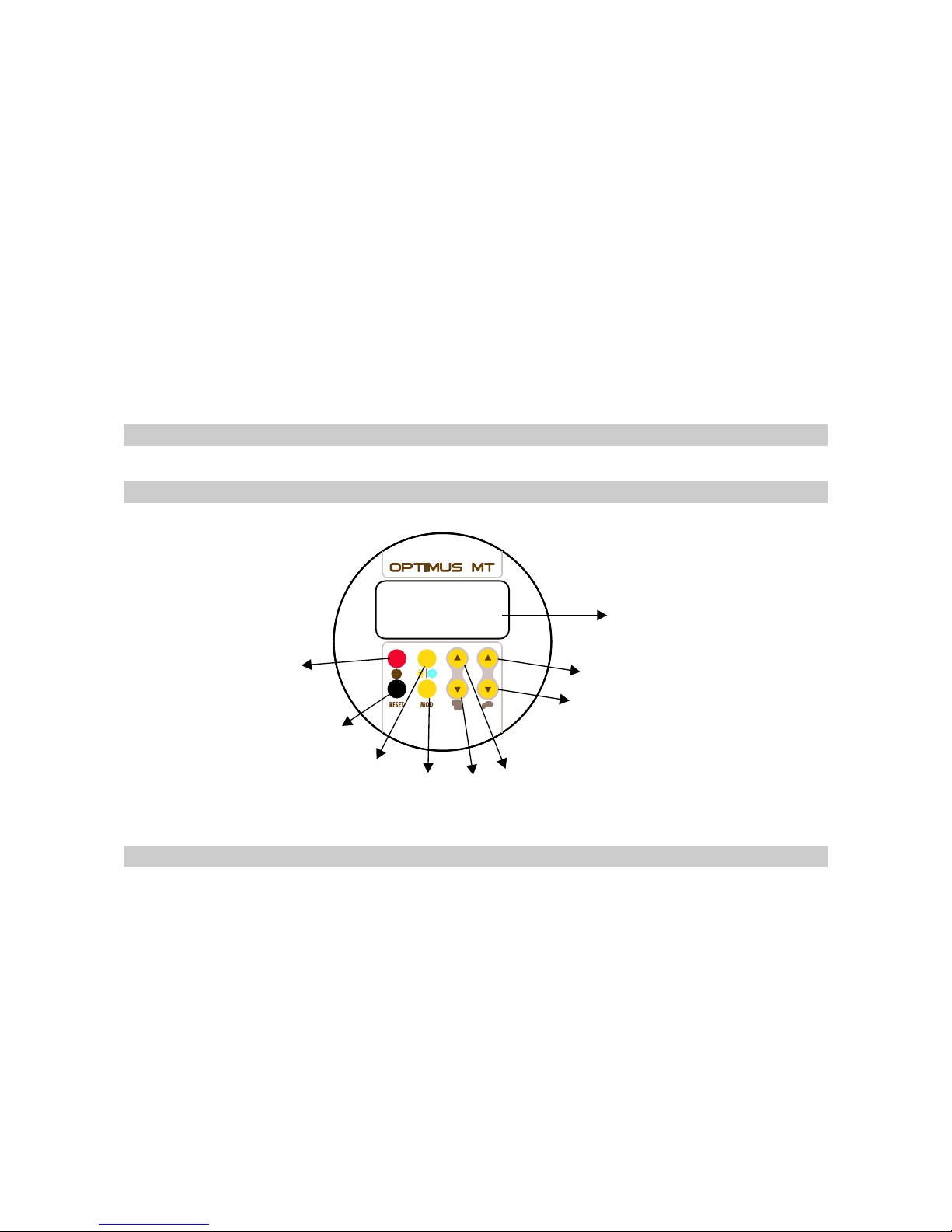
Display board LCD in the user module
SW8
SW 7
SW2
Button - Operation function
This button shuts down/ opens out the boiler (the boiler is still connected to the
tension). In the module Off the board is deactivated completely excepting the symbol 1.
When activating, the activated symbols appear on the LCD display while the symbol 1
disappears
Summer/ winter: Pressing this button, you select summer or winter module. The activated
symbols are two for the summer (in this module, any value of the temperature is
displayed in stand-by, while, if there is any DHW demand, the DHW setting temperature
will appear) and 3 for thewinter module.
Reset from blocking: reset if theboiler isin Err E2, otherwise there will beno result.
On/Off:
Fig 1. The control board for OPTIMUS MT
SW3
DISPLAY
SW 5
SW1
SW6
SW4
SW7
SW2
SW8
Page 14
14
SW 4
SW3
SW6
SW1
SW5
(-)
(+)
(-)
(+)
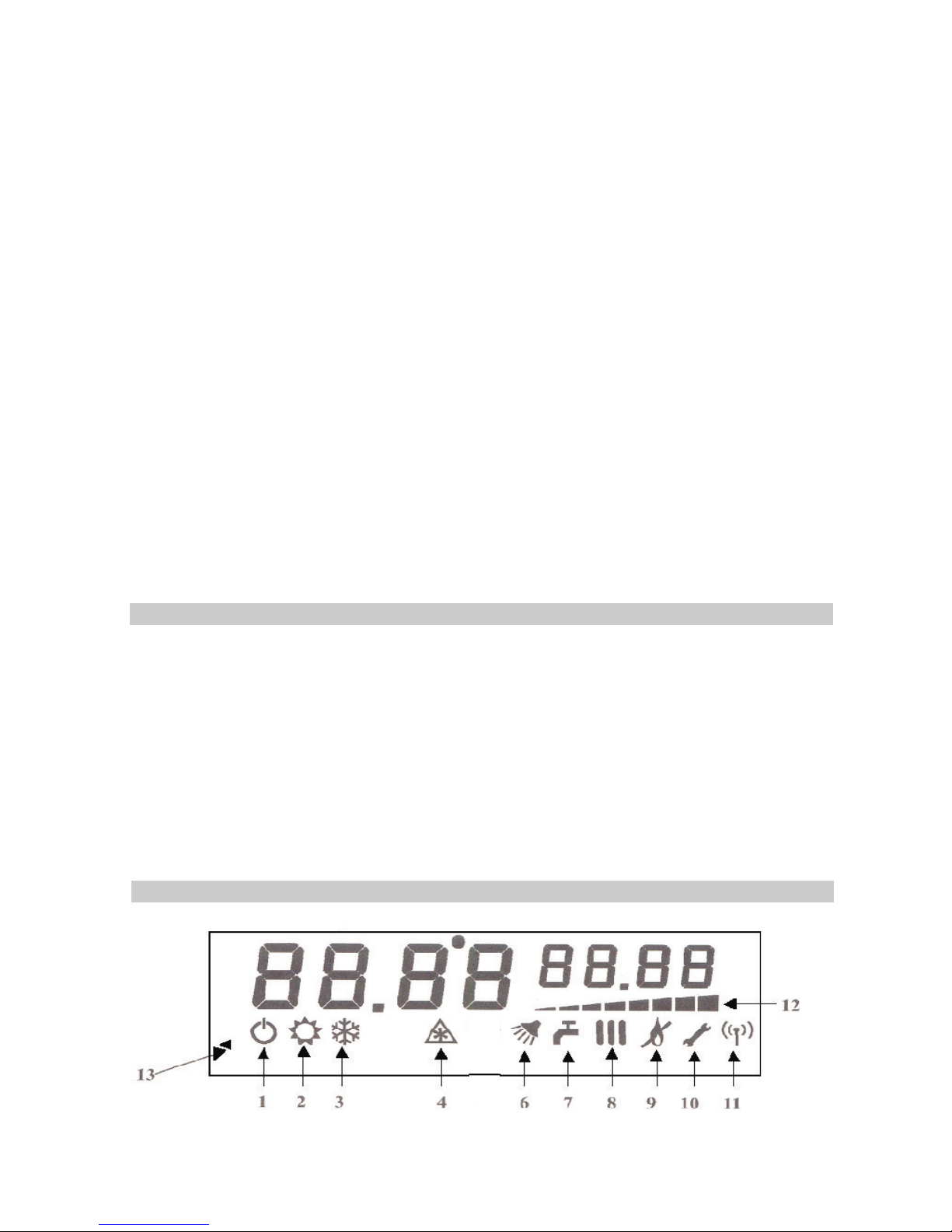
Comfort: pressing this button, you select the comfort module(symbol 6 on) and the
set range of the domestic circuit may decrease. Press again to cancel it (symbol 6
off).
Heating: Pressing the button once, the temperature preset by the heating is
displayed; the setting will decrease if you keep pressing. While visualizing the set
point by the heating, the symbol 8 is flickering. If the external probe is activated, the
temperature of the core circuit will not be changed directly, but two different
parameters will decrease: the wanted temperature into the room and after 5
seconds the symbol "- -" will appear on the display and it holds for one second,
then the dispersion coefficient into the building is displayed and may be changed.
Heating: Pressing the button once, the temperature preset by the heating is
displayed; the setting increases if you keep pressing. While visualizing the set point
by the heating, the symbol 8 is flickering. The heating, the temperature from the
room and the dispersion coefficient may be increased in the same way as SW3.
DHW: Pressing the button once, the preset temperature of the DHW is
displayed; if you keep pressing the setting will decrease. While visualizing the set
point by the heating, the symbol 7 is flickering.
DHW: Pressing the button once, the presettemperature ofthe DHWis displayed; if
you keep pressing the setting will decrease. While visualizing the set point by the
heating, the symbol 7 is flickering.
Chimney sweep" function: If you press SW7 and SW8 simultaneously, With the boiler
in Off position, youwill activate"Chimney sweep"function, thereleased temperature is
displayed and the symbol 5 starts flickering. After the normal starting cycle of the
heating it starts at maximum capacity. This situation persists till the temperature of the
core circuit reaches a safety threshold, after which the heat is deactivated andit will be
activated again in the moment that the temperature reduces below the limit. Any DHW
demand activates this function, but it may be done manually by pressing the button
SW7 and the symbol 5 willvanish.
-the heating system 30-80ºC
-the heating from bottom system 15-40ºC
-domestic hot water 30-60ºC
-DHW comfort 35-45ºC
-External sensor:
the temperature in the room 10-30ºC
dispersion coefficient 5-35ºC
-ignition power (soft-start) 0-99% of modulation current
-max. heating power 0-99% of modulation current
-max. fan speed 0-99% of fan speed
-min. fan speed 0-99% of fan speed
SW7+SW8
Values range controlled by the display panel LCD
Electronic board operating
Page 15

15
DHW module in case of monothermal boilers (symbol 7 on)
The heating module (symbol 8 on)
Comfort plus function (symbol 13)
Anti-frost function (symbol 4)
"Chimney-sweep" function (symbol 5)
The self-checking system and the protection function
Ignition demand in the DHW module takes priority of the heating module. The burner
ignition takes place when a DHW demand appears; the boiler tries to supply hot water to the
user at a preset temperature. The demand is detected through the flowmeter. In this case, the
pump runs. If the hot water temperature is higher than the preset value, the boiler will shut
down. As soon as the heat wasted, the boiler is activated again.
If the boiler is on the winter programme and by deactivating the room thermostat, the domestic
water temperature is lower than the one set before, the boiler will carry out the ignition at softstart power, the flame modulation starts and keeps running till the boiler reaches the running
position. If the water temperature is higher than the previous set limit, the boiler will shut down
but the pump will still be active; re-ignition occurs when the water temperature decreases below
the set value, on condition that a lapse of time "of preventing from appearing the frequent
cycles" have passed. The maximum power of the boiler in the heating module is set by means
of the buttons from the control panel during
the heating.
Symbol 13 inermitent - the conthrol system of boiler is achieving the mentain of temperature in
the primary circuit as so, at the request of DHW the time necessary for reaching the setted
temperature to be smaller then 5 seconds. This function is activated automatically at first
request of DHW and remains activated during 60 minutes.
When the sensor of the system detects a temperature lower than (6ºC), the burner is
activated in the heating module and the pump starts running. This state persists until the
cancellation temperature of the anti-frost function is reached (20ºC).
This function is created specially to cancel the normal adjustment of the boiler control,
allowing it function at the maximum heating power. The function is useful during installation and
the moment when the combustion products are verified according to the current standards. The
function may be deactivated manually from the control board or at any other DHW demand.
The system is provided with several diagnostic functions, signalling the operating position of the
boiler and the disturbances type which may occur on the control board display:
-the domestic water temperature:
the heating temperature in ºC (from 0ºC to 99ºC) or the DHW system is displayed ( if available)
-blocking the adequate temperature (irregularity):
in case of a failure in detecting the flame at the end of the three ignition cycles, the mother is
to block and the symbol flickering ErrE2 occurs on the control panel display.
-parasite flame (irregularity)
in case of a presence of a parasite flame, the symbol Err E1 flickering occurs.
Page 16

16
- insufficient pressure of the water in the hydraulic core circuit (irregularity)
- Absence of draft on start (irregularity):
The boiler shutting-down in safety conditions.
The pressure visualizing
:
in case the pressure sensor measures an insufficient pressure of the water in the system, (<0,5
bar) the burner and the pump are deactivated and the flickering intermittent symbol Err E1
occurs on the display.
Disturbance of a temperature sensor (irregularity):
1.Sensor for the central heating water: any disturbance of the sensor caused by a wrong
contact or a short-circuit leads to the immediate deactivation of the burner, pump and the
flickering intermittent symbol Err E1 occurs.
2.Sensor for DHW: any disturbance of the sensor caused by the wrong contact doesn`t lead to
the immediate deactivation of the burner but to displaying the flickering intermittent symbol Err
E4 for monothermal boilers.
In case the pressure switch doesn`t commute the
TW pre-cleaning in due time, the boiler won`t start running and the intermittent symbol Err E5
will occur after 10 seconds. This irregularity vanishes when the flame is detected at the end of
the operating cycle.
-Removing the combustion products causes the activation of the safety devices (irregularity):
OPEN CHAMBER
The safety devices of the combustion products are activated and cause the boiler automatic
shutting down, the intermittent symbol E5 occurs on display. This irregularity disappears only
pressing the button SW3. In case the limit thermostat (LT) is activated, the system will shut
down automatically and the intermittent symbol Err E8 occurs on the control panel display. This
irregularity persists even if LT is deactivated. To reset the normal operating system it is sufficient
to press the reset button SW2.
In case the final user establishes that the appliance has an abnormal running, if the error codes
keep displaying or if the appliance manifestations can not be understood, he has the obligation
of shutting-down the boiler as soon as possible and in maximum safety conditions. The user
must perform the following operations:
* press STAND BY and the boiler shuts down
* disconnect the boiler from the electric power supply circuit by unplugging
* Disconnect the gas supply circuit by switching on the gas valves
* Interrupt the DHW and the DCW circulation by switching on the gas valves corresponding to
these circuits.
After boiler shutting down in maximum safety conditions, the user will call the service unit he
belongs to (see chapter 1, subchapter 1.4).
The pressure from installation is displayed and it is useful to installation filling up. The
beneficiary will check recurrently whether the pressure in installation has lowered below the
value set on filling.
The pressure will maintain between 1-2 bars. If the minimum pressure lowers below the value of
0,5 bars the boiler will display the E1 signal and it will shut down. If the pressure exceeds the
value of 3 bars, the safety relief valve will open and it will release the system from the
accumulated pressure.
Page 17

17
THE BOILER RUNNING
ANOTHER FUNCTIONS CONCERNING THE BOILER SAFETY
1) The pump post-circulation
2) The pump anti-blocking function
3) The 3- way valve anti-blocking function
The antifreeze function
The boiler running will be < without permanent control> provided automatically by the controllers
installed on the boiler, and eventually by the environment devices (room thermostat). These
devices must be set at thetemperature corresponding to the controlled environment.
a. the temperature settingon the heating circuit will be between 40-80º
b. the room thermostat will be set atthe wanted temperature in the room.
In case the central heating installationis drawn off the tensionduring the cold period or in case,
due to some disturbances, the water temperature from the boiler will be below zero degree for
more than 2-3 hours, the boiler, the heating installation and the domestic water installation will be
exhausted.
Also the boiler supply will bedisconnected fromthe current and gases net.
Each time the boiler is shutting down (in the heating module), the pump keeps running for a
short period of time so that it could prevent from water overheating in the main heat
exchanger.
If the boiler doesn`t effect any cycle during a 24 h period, the pump will start running for a few
seconds to avoid blocking caused bythe non-running.
On each pump shutting down, the deflection valve is activated for one second and then it
reverts to the initial position.
4)
When the temperature sensor detect a temperature lower than 6oC,the burner is activated in
the heating module and the circulationpump start to operate.
Page 18
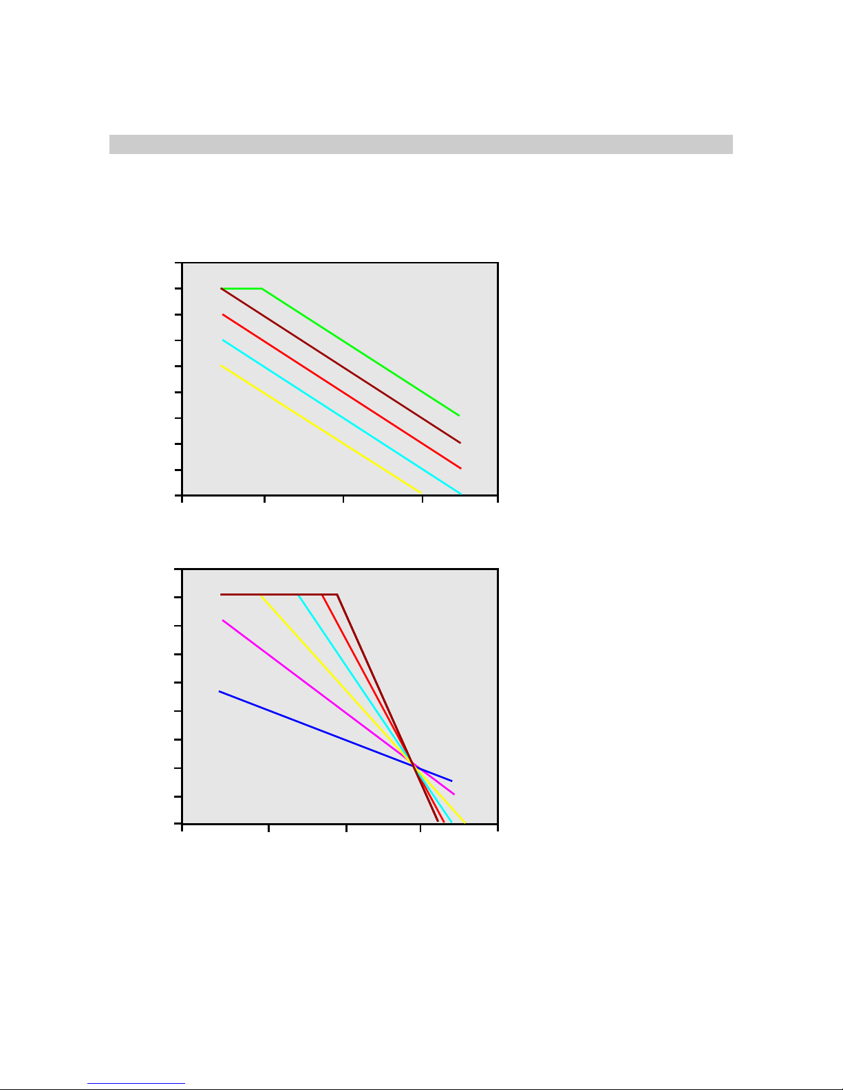
Additional facilities you may obtain:
- Mounting an exterior temperature sensor, the boiler adjusts the heat carrier temperature
depending on the temperature value from outside the building, the room wanted temperature
and the heat leakage coefficient through the building walls.
90
80
70
60
50
40
30
20
10
0
- 40 - 20 0 20 40
Outdoor temperature [°C]
Recommended temperature [°C]
90
80
70
60
50
40
30
20
10
0
- 40
- 20 0 20
40
Outdoor temperature [°C]
Recommended temperature [°C]
T. amb = 30°C
Ke = 35
Ke = 5
T. amb = 10°C
The heating circuit temperature
diagram depending on the
outdoor temperature at
different set room
temperatures and Ke=1
The heating circuit temperature
diagram at different set
dispersion coefficients
Heating temperature=Room temperature +Ke*(room temperature-outdoor temperature)
Room temperature-the temperature of the room
Outdoor temperature-the external temperature
Ke- dispersion coefficient
18
Page 19

19
Delivering to the user
RECOMMENDATIONS FOR YEARLYCHECKING
It is compulsory that the qualified personnel to instruct the user in great detail about the following
aspects on boiler starting:
The boiler starting and the shutting-down procedures, in safety conditions by checking the
following elements:
* the electric powersupply respectingthe polarity
* gas supply
* the central heatingcircuit supplyand loading
* the filling valvemust beclosed
* the pressure ininstallation by the manometerdisplaying fromthe controlpanel (1-2 bars)
* the valves from the DHW circuit should be opened
The running mode of the boiler and the possible problems which may occur. Also, the
importance of each buttonor switch from the control panel will be explained.
The user is warned that a water pressure falling in the system is caused by the heat carrier loss
which must be rectified before usingthe boiler again.
It is recommended that the user should ask for a checking of the boiler running by an
authorized person at least once ayear.
The user is warned upon theprecautions against freezing.
The instructions manual is delivered tothe user.
At the end of the instruction they must sign a document of putting into service, as he
assimilated the proper mode of the boiler utilization. This document is signed by the authorized
person too who performs the puttinginto service, who trained.
The person who performs the starting has the right of refusing the putting into service of the
boiler if he establishes that there are some irregularities, and he won`t contract the document till
these irregularities are remedied.
The one who performs the puttinginto servicehas notthe obligation of rectifying themounting
errors but he assumes the responsibility that the installations correspond to the chosen boiler from
the functional and constructive point ofview.
It is compulsory tocheck theboiler at a least two years period.
For a good running of the boiler and prolonging the boiler life it is necessary to be checked by
an authorized person at least once time a year. It is recommendable that this checking to be done
before the cold period, when the boiler won`t be used at the maximum capacity. The following
operations will be performed as: the main burner running is controlled and the burner is cleaned in
case this thing is compulsory; the boiler exhaust flue is checked and cleaned; the gas valve
controls are verified; the pump is verified; the scavenging system running is verified; the air
pressure switch running and the flue system tightness are verified; the combustion correctness is
checked, by analysing the exhaust gases; the gas supply systemtightness isverified, thedistrict
heating and the DHW circuits tightness are checked, the electrical installation is verified..
Page 20

20
STAMPING, DOCUMENTS, PACKING, STORAGE, QUALITY AND
GUARANTEE CONDITIONS
STAMPING
PACKING
STORAGE
SHIPMENT
QUALITY AND GUARANTEE CONDITIONS:
A designated card is fixed on each product by sticking with following:
* The manufacturer company
* The name of the product
* The serial number and the lot
* Number of CE type examination certificate
* Quality Department authority sign
* The boiler type and size
* The gas type which the inputrated pressure has been set for
The boilers will be packed into the cardboard boxes, protected byboxboard angles.
The boiler will be delivered withall the installed components, less those from the Appliance book.
The boilers storage is achieved in dry places and protected by the bad weather and the chemical
agents.
During the shipment all the necessary measures must be taken to avoid the strokes or the
boiler damaging.
The guarantee is given if thefollowing conditions are provided:
* The correct installation andsetting by the authorized personnel.
* The yearly examinations are achieved on beneficiary demand and at the expense of the
beneficiary, the first year examination is compulsory to maintain theguarantee for the first two years
of usage.
* The exchanged components will be warranted for one year. This doesn`t mean that the
set guarantee period will prolong forthe entire device.
* The guarantee period prolongs from the moment the user has claimed the device
breakdown and till the time thedevice will be putted into service again.
* The heating installation designing and execution should be performed by qualified
person and a qualified unity (ifneed be).
* It is necessary to check andclean the installation before mounting the boiler in case of an
existing installations.
* The interventions during the warranty period will be performed only by the authorized
personnel of the manufacturer company.
Any repair by another person except the authorized personnel of the manufacturer company
leads to warranty loss.
DOCUMENTS
Each boiler is delivered with:
Technicalmanual, quality and guaranteecertificates,CE conformitydeclaration.
Page 21

RESPONSIBILITIES DURING THE WARRANTY PERIOD
MAXOPTIMUS Boiler C 15 SPV 24 MEFM
MALFUNCTIONS WHICH REFER TO THE MANUFACTURER’S RESPONSABILITY
No.
Crt..
1
2
3
4
5
6
7
8
9
10
11
12
13
14
Irregularities
Interrupted course or
defective sensors
Central heating
DHW
It doesn`t run or
it runs defectively
Defective
Pressure losses
Burner distortions
A defective running
You can`t operate the wanted
setting any more by pressing.
There is no information
displayed.
Any anormal function
determined by
electronical board
Defective ignition transformer
There is no spark between
the electrode and the burner
or it loses the spark due to
the defective isolation
or there is no flame.
Defective
Defective
Defective
The component
Temperature
sensors
The gas valve
The heat
exchanger
Ignition/
ionization electrode
Parasite spark
Replace the ignition/
ionisation electrode
The expansion vessel
The burner
The minimum
pressure sensor
The control board
(switch)
The electronical
board
Ignition
transformer
Ignition/ ionization
electrode
Overheating
thermostat
The fan
The air pressure
switch
Possible
error signal
E1
E1
E3
E4
E2
E7
E2
E5
E5
Repair mode
Renew the course
or replace the sensors
Replace the
gas valve
Replace the
exchanger
Replace the
expansion vessel
Replace the burner
Replace the
pressure sensor
Renew the course.
Replace the panel.
Replace the board
Replace the ignition
transformer.
Setting the distance.
Replace the electrode.
Replace the
overheating thermostat
Replace the fan.
Replace the
air pressure switch
21
Page 22

MALFUNCTIONS WHICH REFER TO THE RESPONSABILITY OF THE UTILITIES PROVIDER
No.
Crt..
Causes
The component
The disturbed
system
Possible
error signal
Repair
mode
1
2
3
1
2
3
4
The boiler doesn`t
run, there is no
signal on display
The boiler starts
but there
is no flame.
The flame fires up
and then it puts out
The central heating
does not heat.
Electrical power supply
deficiency, inadequate
power circuit,
blown safety fuse
The gas valve is closed, the
ignition pressure is too low,
pressure controller isn`t set
adequately, there is air in the
gas pipe, the pressure is
lower than 0,5 bar
on the central heating
The reversal of phase with zero
The winter/summer switch is on
summer, the boiler was set
to run at a too low temperature,
the room thermostat is set at a
too low temperature, the pipes
lay-out is through a below 0º C
area and it froze, there
is air in installation.
E2
E2
The user calls the
authorized service
unit he belongs to.
The user calls the
authorized service
unit he belongs to.
The user calls the
authorized service
unit he belongs to.
The user calls the
authorized service
unit he belongs to.
The boiler doesn`t
run, there is no
signal on display
The boiler runs
intermittently .
Damage, noises
or vibrations
The running
with unsteady
temperature on
domestic water
- electrical power supply
deficiency (inadequate
electrical circuit,
blown safety fuse)
gas deficiency or unadjusted
inlet pressure into the
boiler or unadjusted
outlet pressure (burner)
Too low pressure
on domestic
water (>1bar)
Electrical
circuit
Gas supply
circuit
The domestic
water circuit
E2
Call the
electric
power
supplier
Call the
gas
supplier.
Call the
domestic
water
supplier.
MALFUNCTIONS FOR WHICH THE MANUFACTURER IS NOT RESPONSIBLE
No.
Crt.
Causes
The
component
Possible
error signal
Repair mode
22
Page 23
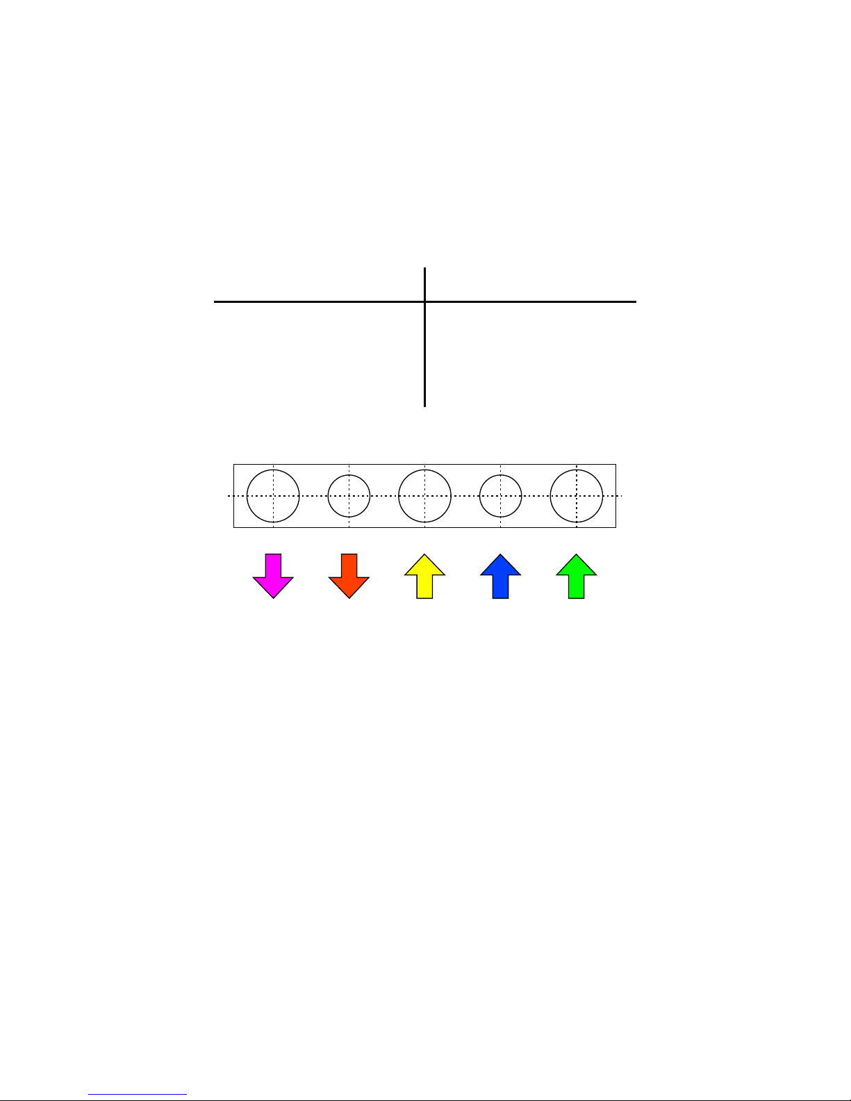
LISTS AND PLANS NECESSARY FOR MOUNTING AND
PUTTING INTO SERVICE
Plan 1
The couplings arrangement of Wall hung gas boiler with forced draft
MAXOPTIMUS C15SPV24MEFM
THE Coupling
1. DHW inlet
CH turn DHW gas supply cold water CH return
2. DHW outlet
3. Central heating turn
4. Central heating return
5.Gas supply
1/2 1/2
” outside thread
”
”
”
3/4”
3/4 3/4 -
-
outside thread
outside thread
outside thread
outside thread
DIMENSION
23
3
2
5
1 4
Page 24
24
A
1
2
4
15
B
C
D E
6
7
16
12
14
13
9
19
10
8
11
5
3
17
18
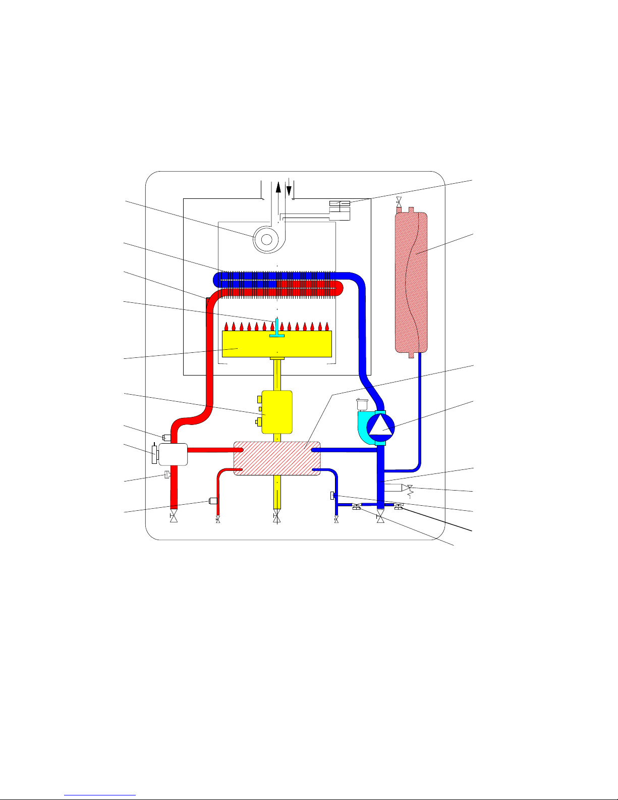
Plan 2
Hydraulic diagram of The Wall hung gas boiler
with forced draft OPTIMUS - C15SPV24 MEFM
1.Electrical fan with Hall sensor
2.main heat exchanger
3.secondary heat exchanger
4.ignition/ionization electrode
5.electrical pump with exhauster
6.burner
7.gas modulator
8.3 bar safety valve
9.filling valve
10.flowmeter for the sanitary circuit
11.automatic by-pass
12. 3- way valve
13. temperature sensing probe for DHW
14. minimum water pressure switch
15. safety thermostat
16. temperature sensing probe for heating
17. expansion vessel
18. air pressure switch
19. drain valve
A. Heating turn
B. DHW outlet
C. gas inlet
D. cold water inlet
E. heating return
Page 25
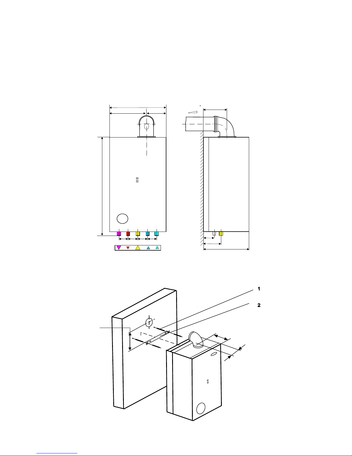
The Couplings diagram for the wall
hung gas boiler with forced draft
OPTIMUS MT- C15 SPV 24 MEFM
Plan 3
25
1
2
700
65 51 64 65
A B
C
D E
3/4” 3/4” 3/4”
1/2”1/2”
415
226
189
Panta 3% (aprox. 2 )
134
75
280
Gaz
Apa
125
155
189
94
Page 26
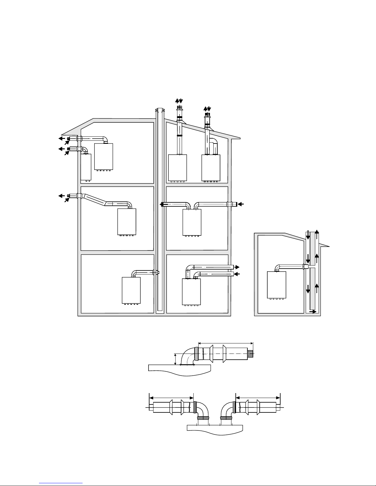
Plan 4
Typical flue system applications for the
wall hung gas boiler with forced draft
C15SPV24MEFM
26
C12
C12x
C
12
C12x
C82
C32
C32x
C42
C22
C22
COAXIAL FLUE
TWIN FLUE
Lmin=1m; Lmax=3m
Lmin=1m; Lmax=5m
Lmin=1m; Lmax=5m
95
Page 27
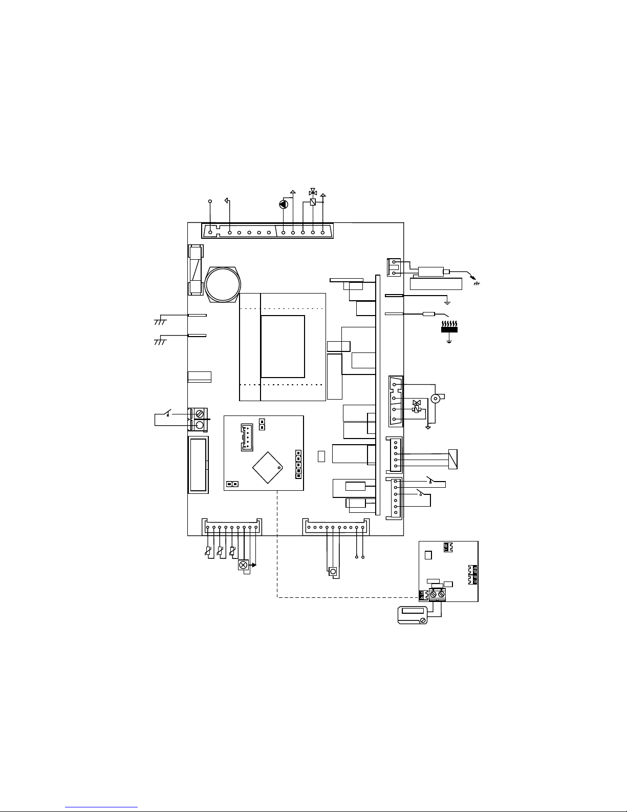
Plan 5
Electrical diagram for the wall hung gas boiler
C15SPV24MEFM
27
LIVE
NEUTRAL
PUMP
3 - WAY VALVE
N.C.
N.O.
1
J5
J1
56
EARTH
EARTH
ROOM
THERMOSTAT
LOCAL USER MANUAL
INTERFACE
55
54
J7
J13
J14
J2
J17
J16
J4
J9
J3
J18
TR 2
EARTH
FLAME
ELECTRODE
FAN
JP 1
CH PROBE
DHW PROBE
EXT. PROBE
FLOWMETER
RRESSURE
TRANSDUCER
MODULATOR COIL
CRONO TERMOSTAT
OPEN-THERM
961 INTERFACE
APS
GND
VCC
GAS VALVE
HALL SENSOR
SAFETY THERMOSTAT
INPUT
INPUT
0 Vdc
0 Vdc
+5 Vdc
+5 Vdc
52
51
50
49
48 47 46
45
44
43
42
41
40
39
38
37
36
35
34
33
32
31
30
29
28
27
26
25
22
21
20
19
15
14
TO J3
(TO J9 IF MONOELECTRODE)
13
12
2
1
J20
F1
J11
U3
2
3
4
5
6
7
8 9
10
11
 Loading...