

Page 1

KÖBER LTD DUMBRAVA ROSIE - VADURI BRANCH OFFICE
Branch Office:Vaduri, No. 280, Alexandru cel Bun, Neamt District, Postal Code 617511, Romania
Phone : +40.233.24.17.46, 233.24.19.33, Fax : +40.233.24.19.29
E-mail : , www.motan.rooffi[email protected]
TECHNICAL INSTRUCTIONS
FOR INSTALLATION/ USAGE/ MAINTENANCE
Köber LTD
Vaduri Branch Office
1798
0086
Type: C13SPV36MEF
Type: C14SPV25MEF
Page 2

KÖBER L.T.D. VADURI BRANCH
implements and certifies the Quality Management System,
according with standard EN ISO 9001:2008.
This certificate assure the conformity of our products.
The quality of our product is the result of permanent
investments in implementing of the highest development and
research technology, profesionalism, experiency and
dedication of employers.
The technical instruction must to be available any time.
The technical instruction is the exclusive property of
KÖBER LTD , VADURI BRANCH
It is forbidden to copy and to distribute the technical instruction
in any other way without the prior written aproval of
KÖBER LTD , VADURI BRANCH
DUMBRAVA ROSIE -
DUMBRAVA ROSIE
DUMBRAVA ROSIE
Page 3

page
1. DESCRIPTION OF THE APPLIANCE
1.1 GENERAL DESCRIPTION
1.2 BOILER MODELS
1.3 GENERAL INSTRUCTIONS CONCERNING THE BOILER SAFETY
2. BOILER SPECIFICATION
2.1 TECHNICAL DATA
2.2 MAIN COMPONENTS
2.2.1 BURNING SYSTEM (see picture no.1)
2.2.2 HYDRAULIC SYSTEM ( 2)
2.2.3 CONTROL SYSTEM ( )
3. MOUNTING AND INSTALLATION INSTRUCTIONS
3.1 ACCORDANCE WITH THE CURRENT REGULATIONS
3.2 MOUNTING THE BOILER ON THE WALL
3.3 CONECTING THE BOILER
3.4 CONDENSATE DRAINAGE (see figure no.4)
4. PUTTING INTO SERVICE
5. COMMISSIONING
5.1 VERIFY THE POWER SUPPLY TO THE BOILER
5.2 THE FILLING UP
5.3 CONNECT AN ROOM THERMOSTAT AND AN EXTERNAL PROBE
5.4 VERIFY THE GAS TYPE
5.5 THE MEASUREMENT OF STATIC PRESSURE
5.6 THE MEASUREMENT OF DYNAMIC PRESSURE
5.7 VERIFY THE EXHAUST SYSTEM
5.8 INITIAL LIGHTING
5.9 INSTRUCT THE USER
6. USAGE INSTRUCTIONS FOR THE END USER
6.1 CONTROL PANEL
6.1.1 BOILER CONTROL UNIT - POWER ON
6.1.2 “CENTRAL HEATING” MODE (symbol 8 ON)
6.1.3 “DOMESTIC HOT WATER - DHW” (symbol 7 ON)
6.1.4 SYSTEM WATER PRESSURE CHECKING
6.1.5 ADDITIONAL FACILITIES
6.1.6 THE BOILER SHUTTING-DOWN IN SAFETY CONDITIONS
see picture no.
see picture no.4
6.2 FUNCTIONS CONCERNING BOILER SAFETY
6.3 ERRORS DETECTION
6.4 DELIVERY THE BOILER TO THE END USER AFTER INSTALLATION
TABLE OF CONTENTS:
3
4
5
6
7
7
8
8
9
11
12
12
13
13
19
20
21
22
22
23
25
25
25
25
26
26
27
27
30
31
31
31
31
32
32
33
34
Page 4

6.5. ROUTINE SERVICING
6.6. STORAGE, MARKING, DOCUMENTS, PACKING, TRANSPORT
6.7 QUALITY AND GURANTEE CONDITIONS
6.8 RESPONSIBILITIES DURING THE WARRANTY PERIOD
7. APPENDIX: LISTS AND PLANS FOR MOUNTING AND INSTALLATION
Plan 1 - The couplings arrangement
2 - Hydraulic diagram
3 - The couplings diagram for MKDens36
5a, 5b - Typical flue system applications
6 - Terminal clearances for flue installation
7 - Lists and plans for mounting and installation
8 - Electrical diagram
Plan
Plan
Plan 4 - The couplings diagram for MKDens25
Plan
Plan
Plan
Plan
34
35
36
37
39
39
40
41
41
43
44
45
47
TABLE OF CONTENTS:
Page 5

PLEASE RESPECT STRINGENTLY THE INFORMATIONS OF
TECHNICAL INSTRUCTION. OTHERWISE, CAN APPEAR FIRE AND BLOW
UP RISK WHICH CAN LEAD AT MATERIAL PREJUDICE, PERSON'S INJURY
OR EVEN DYING.
VERYIMPORTANT!
IT IS THE LAW THAT ALL GAS APPLIANCES ARE INSTALLED BY A
COMPETEND PERSON. IT IS IN YOUR OWN INTEREST AND THAT OF
SAFETY TO ENSURE THAT THE LAW IS COMPLIED WITH.
DO NOT STORE OR USE FLAMMABLE MATERIALS IN THE VICINITY
OF GAS BOILER.
DO NOT USE THE GAS BOILER IF ANY OF HIS COMPONENTS HAVE
BEEN FLOODED.
INFORM URGENTLY THE SERVICE PEOPLE TO INSPECT THE GAS BOILER
AND TO REPLACE THE FLOODED COMPONENTS.
IN CASE YOU FEEL GAS FLAVOUR, RESPECT THE FOLLOWING
OPERATIONS:
- DON'T SWITCH ANY LIGHT OR FLAME
- DON'T TOUCH ANY LIGHTING SWITCH
- CALL URGENTLY THE GAS SUPPLIER. DON'T USE THE PHONE IN
THE BUILDING WHERE IS INSTALLEDTHE GAS BOILER
- IF YOU CAN'T CONNECT WITH THE GAS SUPPLIER, CALL THE
FIRE BRIGADE.
INSTALLING, COMMISSIONING, ROUTINE SERVICE WILL BE MADE
ONLY BY QUALIFIED SERVICE ENGINEERS, QUALIFIED SERVICE
CORPORATIONS OR BY GAS SUPPLIERS.
THIS APPLIANCE IS NOT INTENDED FOR USE BY PERSONS
(INCLUDING CHILDREN) WITH REDUCED PHYSICAL OR SENSORY
CAPABILITIES, OR LACK OF EXPERIENCE AND KNOWLEDGE, UNLESS
THEY HAVE BEEN GIVEN SUPERVISION BY A PERSON RESPONSABILE
FOR THEIR SAFETY.
1. DESCRIPTION OF THE APPLIANCE
SATEFY MEASURES
3
Page 6

The Motan MKDENS wall mounted gas boiler is a fuel gas consuming
appliance, that has the role of turning the fuel gas power into thermal energy
through burning. This appliance operates unsupervised due to its protection and
control systems.
The boiler consists of many components that are described in the following
chapters.
The gas enters inside the boiler through the gas supply circuit made of a
coupling and a reducing valve, which must be set at 20 mbar for G20 H subgroup.
After the reducing valve, the gas enters the gas valve and, further, the Venturi tube.
The boiler is equipped with an air fan, which ensures the forced draught.
The rotation speed of the fan is variable (control is made by modulation).
In the pre-purge phase, the fan evacuates an air volume to provide a safe ignition.
Otherwise, an explosive ignition might occur due to gas storage from non-operating
periods.
The air delivered by the fan enters the Venturi tube, where it draws in (by
suction) and entrains the fuel gas suppliedby the gas valve. The air and fuel gas are
mixed in the Venturi tube diffuser.The resulted air gas mixture supplies the burner.
The assembly fan gas valve Venturi tube ensures a constant and
optimum air gas ratio at any load of the boiler.
The flame ignition is performed by an ignition electrode, by means of an
ignition transformer. During the combustion, the flame sensing is ensured by an
ionization sensor.
The main heat exchanger is made of stainless steel and has an annular
shape. Inside this cylinder, the combustion chamber is placed. The main heat
exchanger is designed to allow the heat transfer from the combustion gas to the
water with minimal heat leakages.
In case of the Central Heating (CH) circuit, the heat resulted from fuel gas
burning is taken over by the main heat exchanger and sent to the water which is
delivered by the circulating pump through the heating installation.
When the flowmeter detects flow in the Domestic Hot Water (DHW) circuit,
the three-way valve switches from the central heating circuit to the short circuit that
includes the plate heat exchanger; in this case, the heat resulted from fuel gas
burning is transferred to the domestic water.
The system monitoring and control are electronically performed. The boiler
setting is made from the control board (see the chapter concerning this subject).
1.1 GENERAL DESCRIPTION
4
Page 7
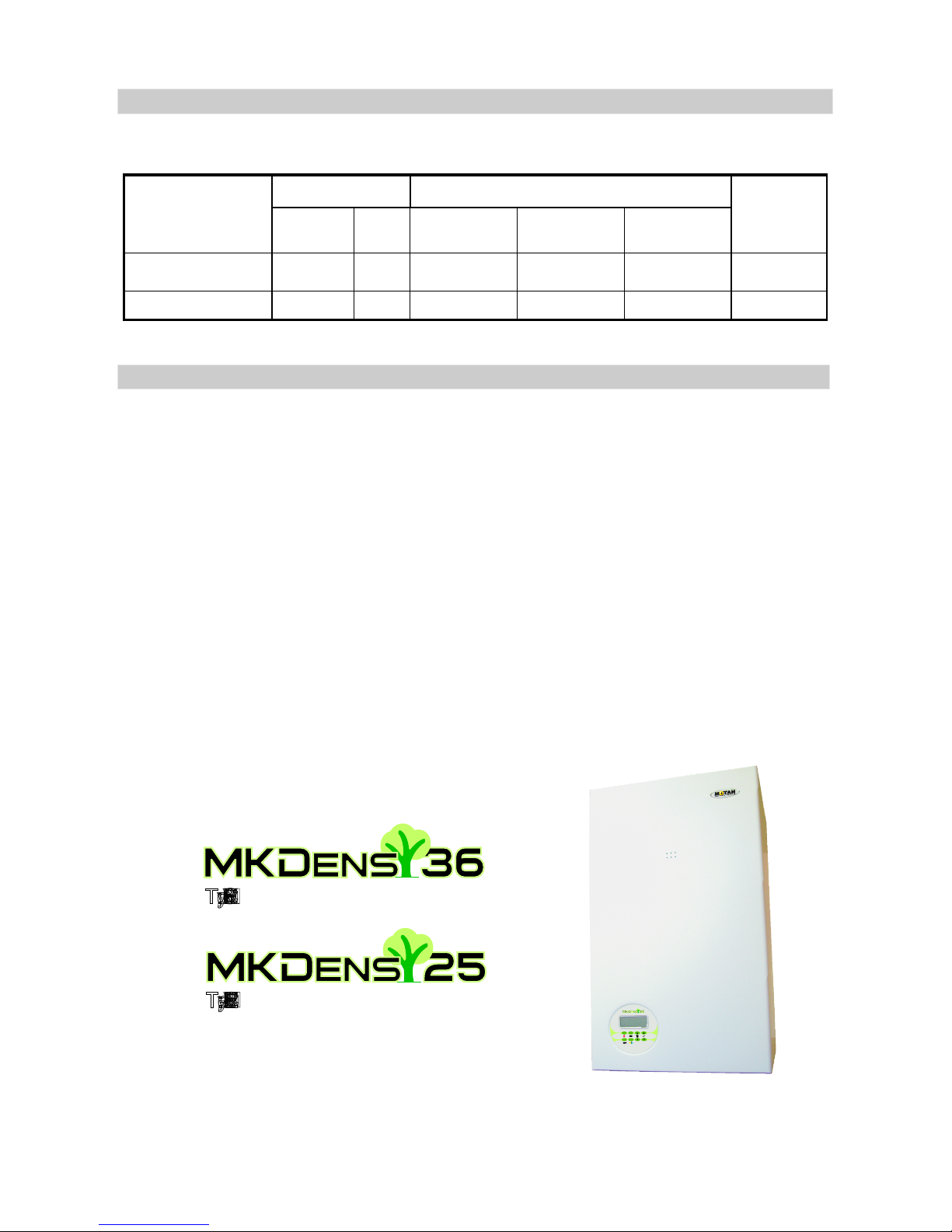
5
C13, C14 - model code
S - with instant delivery of hot water (without external water tank)
P - with circulation pump
V - with sealed expansion vessel
36, 25 - maximum gross output in kW
M - continuous modulating air - gas supply system
E - electronic control and supervision of ignition and flame
F - forced draught
1.2 BOILER MODELS
MODEL NUMBER CODING
TYPE
C13SPV36MEF
C1 SPV MEF4 25
Maximum Output
Accesories
[kcal/h] KW
36
25
Fan Pump
Expansion
vessel
DHW instant
production
30954
21496
X
X
X
X
X
X
X
X
Type: C13SPV36MEF
Type: C14SPV25MEF
Page 8

6
! This manual is part of the product and must be given to the user.
The commissioning and service operations is made only by authorized service
engineers.
Read this manual carefully and keep it carefully for a further application by the
user and by the mounting and installing authorized personnel.
The installation must be to the current Gas Safety (Installation and Use)
Regulations and must be installed by a competent person. The installation, the
putting into service, the service repair operations and the periodical technical
checking are performed only by authorized personnel in accordance with the
current standards and installation code.
All the indications from this manual must be respected; any exception may
cause damages and the manufacturer is not responsible for them.
In case of a defective running of the device, shut it down and call up
immediately one of the authorized breakdown services units .
To guarantee the boiler efficiency and its correct operation it is recommended
that the boiler be checked periodically by qualified personnel, complying with the
manufacturer conditions.
If the device is sold or given, make sure it is delivered with its technical
handbook in order to be consulted by the new user/ installer.
In case of some components damaging there will be used only the original
components. You must have the manufacturer's permission to use some
components from another company. You must obtain the written acceptance of
the producer so that you may use those components.
This boiler will be used properly.Any other use will be considered unsuitable.
There is excluded any contractual or extra-contractual responsibility of the
producer for the damages caused by the installing or usage errors and by the nonobservance of his instructions.
It is compulsory to install a softener filter on the domestic water circuit, a
mechanical impurities filter (Y filter) on the CH installation return and a pressure
controller on the gas supply circuit.
Not submitting to these technical manual regulations and to those from the
warranty certificate leads to warranty loss.
!
!
!
!
!
!
!
!
!
!
!
!
1.3 GENERAL INSTRUCTIONS CONCERNING THE BOILER SAFETY
Page 9
7
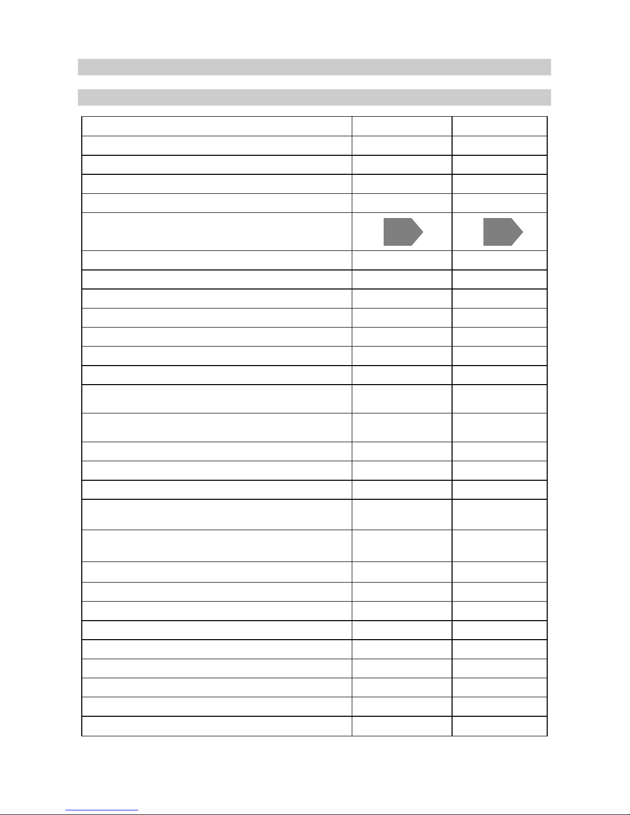
Commercial Name MKDens 25 MKDens 36
Type
C14SPV25MEF C13SPV36MEF
Gas category
Draught type
Combustion chamber
Energy Efficiency Band (natural gas)
Nox class (natural gas)
Net efficiency at rated output (natural gas)
Net efficiency at 30% part-load (natural gas)
Maximum CH gross Heat input, Q
Maximum CH heat output, P (at 100% load)
Weight
Capacity of the heat exchanger
Maximum gas rate (natural gas)
Heating circuit - Flow rate
Heating circuit - Min. and max admitted pressure
Heating circuit - Outgoing water temperature
Connections - inlet-outlet CH
Connections - inlet-outlet DHW
Connections - gas supply
Minimum CH heat output, P
Maximum DHW output, P (at 100% load)
Natural gas pressure on coupling (behind the reducer)
Maximum inlet pressure
Power supply
Power consumption
Minimum CH gross Heat input, Q
Maximum CH net Heat input, Q
Minimum CH net Heat input, Q
I2H (20)
Forced
Closed
5
96.7%
106.7%
26.6 kW
5.2 kW
24.0 kW
4.7 kW
26.6 kW
24.0 kW
24.3 kW
42 kg
1.75 l
2.65 Nmc/h
0.8 mc/h 0.8 mc/h
0.8 si 3 bar
30 - 80°C 30 - 80°C
3/4”
1/2”
3/4”
4.9 kW
24.5 kW
20 mbar
25 mbar
230V / 50 Hz
175 W
230V / 50 Hz
175 W
I2H (20)
Forced
Closed
5
96.7%
106.5%
36.3 kW
8.1 kW
31.8 kW
7.3 kW
36.4 kW
32.8 kW
32.3 kW
48 kg
2.45 l
3.58 Nmc/h
0.8 si 3 bar
3/4”
1/2”
3/4”
7.6 kW
33.3 kW
20 mbar
25 mbar
Maximum DHW gross Heat input, Q
Maximum DHW net Heat input, Q
2.1 TECHNICAL DATA
2 BOILER SPECIFICATIONS
A A
Page 10
8
It is designed to supply the necessary heat for CH and DHW circuits.
It consists of the following elements:
. It must include a reducing valve that will set the inlet pressure at
20-25 mbar NG. It is compulsory to mount a pressure controller on the gas supply circuit.
. The boiler is equipped with an air fan (forced draught).
The rotation speed of the fan is variable; its control is made by modulation.
. It is designed to ensure the gas supply at any load
from the minimum load to the maximum load.
It ensures the mixing of air and fuel gas: the air delivered by fan draws
in (by suction) and entrains the fuel gas delivered by the gas valve; the air and fuel gas
are mixed in the Venturitube diffuser. The resulted air gas mixture supplies the burner.
The assembly fan gas valve Venturi tube ensures a constant and optimum air gas
ratio at any load of the boiler.
. It is a PREMIX type, made of stainless steel and has a cylindrical shape. It
operates on positive relative pressure. The burner output is controlled by means of a
modulating fan.
1. Gas supply circuit
2. Fan (position 1 picture 1)
3. Gas valve (position 2 picture 1)
4. Venturi tube.
5. Burner
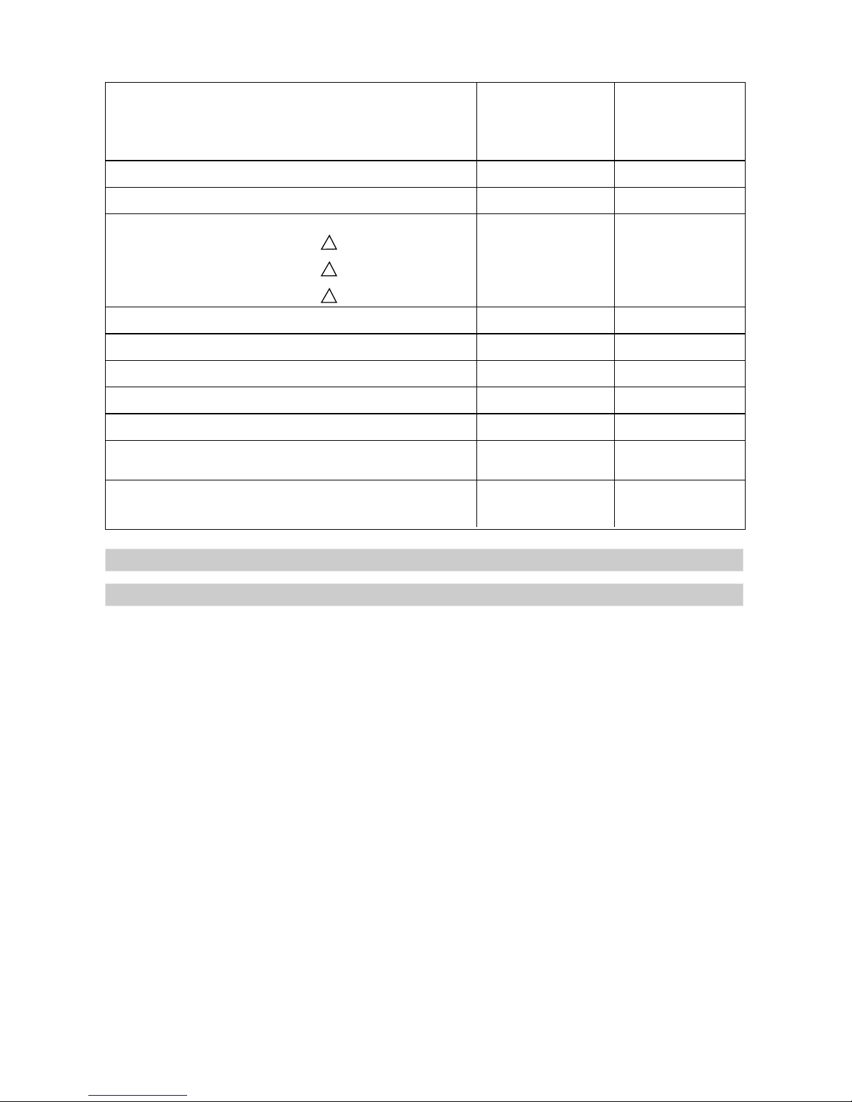
Dimensions (mm) Depth
720 720
Width
Height
With mounted elbow
420 420
340 383
850 850
Expansion vessel
Domestic Hot Water Temperature
DHW flow rate
t = 35°C
t = 40°C
t = 25°C
Domestic cold water pressure
Flue gases temperature
Draught
Concentric flue kit - diameters
Twin flue kit - diameters
7 l
0.2 - 8bar
62 °C 62 °C
0.2 - 8bar
0.015 hPa 0.015 hPa
D100 / D60 D100 / D60
D80 / D80 D80 / D80
3m (maximum)
4m (maximum)
3m (maximum)
4m (maximum)
150 l
8 l
200 l
Length of the concentric flue duct
Lenght of the twin flue duct
Guiding values
Maximum water content in the installation
30 - 60°C
14.3 l/min
10.2 l/min
8 l/min
20.6 l/min
14.7 l/min
11.5 l/min
30 - 60°C
2.2.1 BURNING SYSTEM (see picture no.1)
2.2 MAIN COMPONENTS
Page 11
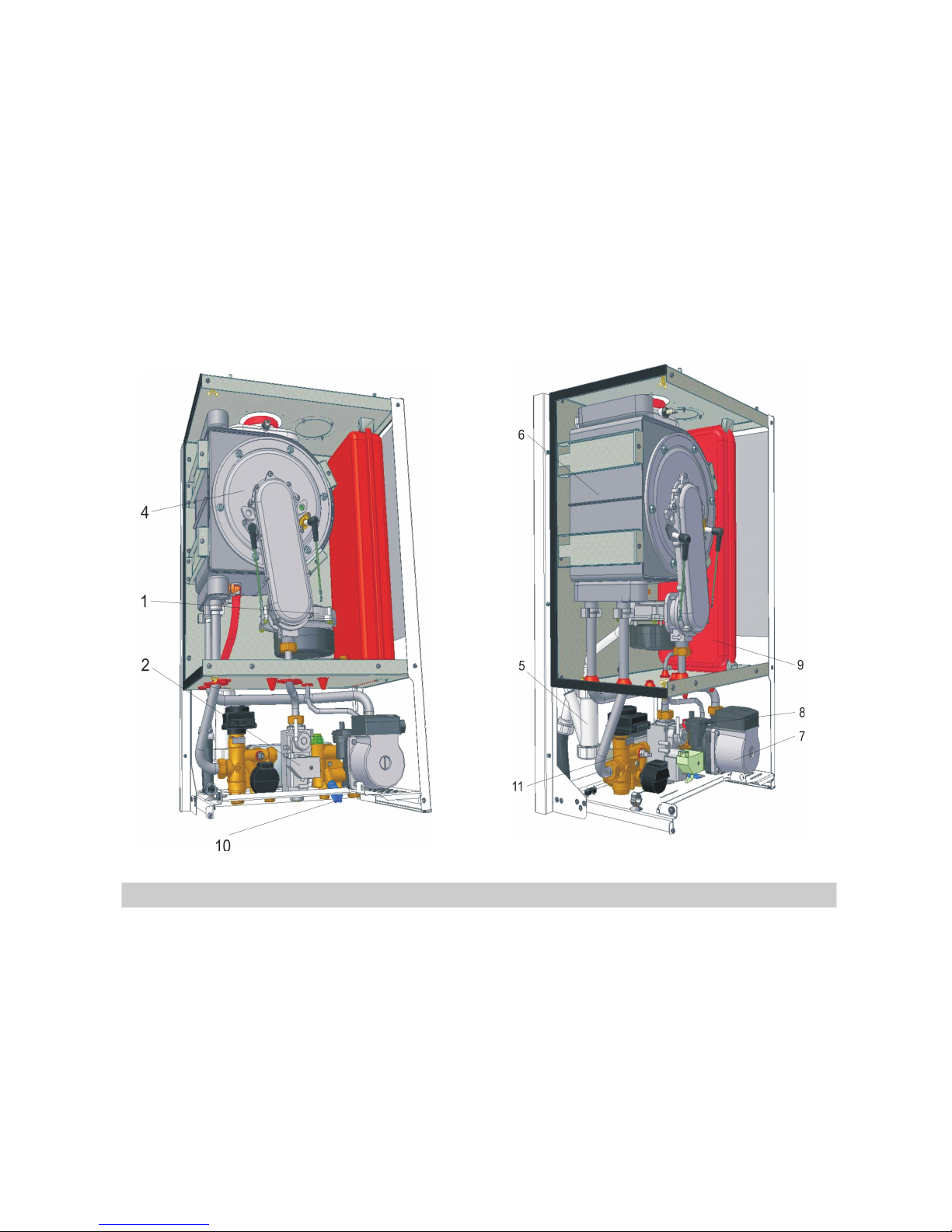
6. Combustion chamber (position 4 picture1).
7. Air and flue gases ducts.
8. Condensate trap (position 5 picture1)
Picture no.1 Picture no.2
1. Main heat exchanger (position 6 picture 2)
It is sealed and has a cylindrical
shape. It is placed inside the main heat exchanger (annular shaped). To reduce
the heat leakages, both front and rear walls of the combustion chamber are
isolated indoor with heat insulating material (ceramics fibers). On the front wall is
placed the burner.
According to the situation, can be concentric or
eccentric type. In both cases, the air duct is connected to outside environment.
The flue gases duct can be connected to the outside environment or to a chimney.
. It is specific to the condensing boilers
and must be always filled with water (condensate). Otherwise, there is a danger
that fumes might escape in to the room and cause poisoning.
It consists of the primary circuit and the secondary circuit (DHW circuit).
The primary circuit takes over the heat resulted from fuel gas burning and sends it
to the heating installation or to the secondary circuit.
The main components of the hydraulic system are:
. Takes over the heat resulted
from fuel gas burning and sends it to the water from the primary circuit. Is made of
stainless steel and has an annular shape. Inside this cylinder, the combustion
chamber is placed.
2.2.2 HYDRAULIC SYSTEM (see picture no.2)
9
Page 12
10
2. Circulating pump (position 7 picture 2)
3.Automatic air vent (position 8 picture 2)
4. Expansion vessel (position 9 picture 2)
5. Safety valve
4.Automatic by-pass
5. Filling system
6. Three-way valve (position 11 picture 2)
7. Plate heat exchanger
.
It is designed to supply the necessary water flow in the primary circuit in
both modes Central Heating and Domestic Hot Water.
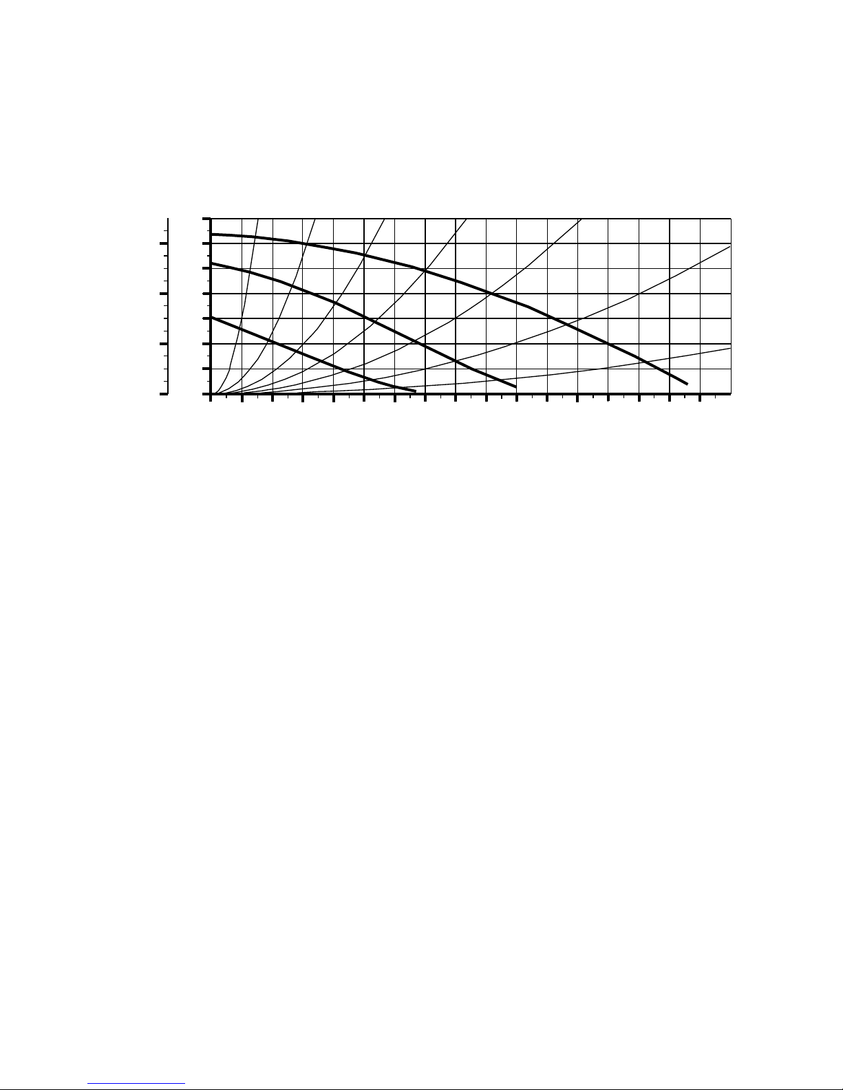
Also, it must be aware of the hydraulic features of the pump, presented in
the figure 1:
.
It ensures the air discharge from the primary circuit. It is mounted on the circulating
pump shell.
.
It allows the expansion of the hot water from the primary circuit. Thus, the hydraulic
overstraining and/or damaging are avoided.
.
It limits the maximum water pressure in the primary circuit to 3 bar. If the water
pressure increases over 3 bar, the safely valve opens automatically and primary
circuit is drained. The safety valve closes when pressure drops under 3 bar.
.
It allows the heat carrier recycling through the heat exchanger and pump, in case of
pressure differences (between the external heat installation turn and return) at
over 0.3 bar.
.
It allows filling of the heating installation with water. It must be used when the
system water pressure is too low. If the system water pressure decreases
accidentally, the heating installation must be carefully checked before the filling
procedure.
.
It allows routing of the thermal agent from the primary circuit towards the heating
installation or the plate heat exchanger - according to the operating mode (CH or
DHW). It is electrically controlled.
.
It takes over the heat carried by the water from the primary circuit and sends it to
the domestic water from the secondary circuit. In this way, the domestic hot water
is prepared.
Pumping height
Pump water flow
0
0
1
1
2
20
2
3
3
4
40
5
6
H
[m]
H Hp
kPa[ ]
0.0 0.2 0.4 0.6 0.8 1.0 1.2 1.4 1.6 1.8 2.0 2.2 2.4 2.6 2.8
Q m /h[ ³ ]
Page 13

11
Is made by the following elements:
It monitors and controls the operation of
the boiler.
Send temperature signals (CH flow and
return) to the electronic board. In this
way, instantaneous values of the
temperatures can be displayed on LCD
and the gas rate can be adjusted in
order to deliver water at the set
temperature. In addition, when CH flow
a n d r e t u r n p r o b e s i n d i c a t e
temperatures over admitted limits,
malfunctions can be signaled.
1. Boiler control unit (position 12
picture 4)
2. CH flow and return temperature
probes (position 13 picture 4)
Picture no.3
3. DHW temperature probe (position 14 picture 4)
4. Overheating thermostat(position 15 picture 4)
5. Waterpressure sensor (position 16 picture 4)
6. Flowmeter (position 17 picture 4)
7. Fan speed sensor
8. Ignition electrode (position 18 picture 4)
9. Ionization electrode (position 19 picture 4)
It sends information about the temperature in the DHW circuit to the electronic
board. Thus, the instantaneous value of the DHW temperature can be displayed
and the gas rate is adjusted according to this information in order to deliver
domestic hot water at the set temperature.
It cuts off the fuel gas supply when the maximum allowed temperature of the
outgoing water is exceeded. In this situation, the boiler goes in lockout state; in
order to exit the lockout state, the RESETkey must be pressed. The thermostat is
placed on the outgoing water pipe, close to the main heat exchanger.
It sends information about the water pressure from the heating system to the
electronic board. In this way, the instantaneous value of the pressure can be
displayed and the user can be notified in case of low water pressure.
It detects and measures the water flow in the DHW circuit.
It sends information about the fan rotation speed to the electronic board. This
information allows optimization of the burning process at any load.
It ensures the spark generation in the ignition stage.
It provides information about the flame status, ensuring a safe combustion. When
the flame is missing, the fuel gas supply is cut off and the boiler goes in the lockout
state.
2.2.3 CONTROL SYSTEM (see picture no.4)
Page 14

10. Flue gases temperature probe (position 20 picture 4)
11. External probe (optional)
12. Chrono-thermostat or room thermostat (optional)
The control system achieves the following:
It cuts off the fuel gas supply when flue gases temperature exceeds 90°C. It is
placed in the flue gases collector, which is located above the main heat exchanger.
It ensures an optimum temperature of the water from the heating installation,
when the external temperature is in the range -20...20°C.
It keeps the room temperature at the user set value. It is provided on demand
(optional).
Ignition control and flame drop out protection;
Gas rate adjustment according to the user requirements regarding water
temperature;
Temperatures signaling for both CH and DHW circuits;
System water pressure signaling;
Protection against fuel gas cut offs;
Protection against overheating of the heating circuit;
Protection against excessive water pressure;
Protection against water loss in the primary circuit;
Protection against clogging of the condensate drain system.
!
!
!
!
!
!
!
!
!
12
The EC type examination certificates eliberated for this types of combi
boilers, by official and autorized bodies, shows the accordance of the appliance
with the current regulations and gives the presumption of the conformity with the
GasAppliances Directive, Low Voltage Directive and Electromagnetical Directive.
This chapter addresses both to the qualified personnel that
performs the boiler installation and to the beneficiary that is concerned that
the mounting and installation of the boiler are performed following the
safety rules in operation of all the installations which contribute to the good
running of the boiler.
THE BOILER INSTALLATION IS NOT THE SAME WITH THE BOILER
STARTING.
THE BOILER STARTING MUST BE DONE BY QUALIFIED
PERSONNEL AND AUTHORIZED IN ACCORDANCE WITH THE CURRENT
LEGISLATION.
THERE IS NO GUARANTEE WITHOUT THE AUTHORIZED
PERSONNEL SIGNING THE PUTTING INTO SERVICE STATEMENT, AND
THE COMPANY WITHDRAWS ANY BOILER GUARANTEE OR RUNNING
RESPONSIBILITIES.
3. MOUNTING AND INSTALLATION INSTRUCTIONS
3.1 ACCORDANCE WITH THE CURRENT REGULATIONS
Page 15

The boiler is designed to be use in integrated in heating systems in closed
chambers. It is forbidden to mount the boiler outside the building.
The appliance has the protection level IP 40;
Improper climate conditions of installing the boiler
automaticcaly conduct to warranty lose.
It shall be performed only if all the conditions concerning the connection
of the boiler are respected (see the chapter 3.3 “Connecting the boiler”).
· - Remove the packing.
· - Make two holes on the wall, at a desired height, by using the pattern
drawn on the boiler pack.
· - Fix the two dowels on the wall and then mount the two hooks by
screwing up. The dowels and hooks are provided with the boiler.
· - Fix the boiler on the wall by inserting the hooks into the two holes made
on the posterior side of the boiler.
- Check the stiffness of the boiler fixed on the wall, to be sure that the
structure of boiler is not stressed
ATTENTION!
13
3.2 MOUNTING THE BOILER ON THE WALL
The boiler must be connected to a mono-phase network of 230V / 50Hz
with ground protection, through a 5A fusible plug. The color semantics will be as
follows: brown= phase, blue=null, green/yellow=earth.
Insert the plug into connection, so that the phase of the network to correspond to
the brown wire of the supply cable.
The correct polarity of the supply connection can be identified by using a
multimeter..
Connecting the boiler to the electric power supply, water, gas,
heating installations and air / flue gases ducts can be performed only by
authorized personnel for mounting / installingactivities.
THE CONNECTION TO THE ELECTRIC NETWORK MUST BE
ACCOMPLISHED ACCORDING TO THE CURRENT LEGISLATION AND
STANDARDS.
IT IS FORBIDDEN TO INSTALL THE BOILER WITHOUT EARTH
CONNECTION .
ONLY THE MANUFACTURER OR THE AUTHORIZED PERSONNEL
CAN REPLACE THE ELECTRICAL POWER SUPPLY CABLE IF DAMAGED.
Electric power supply
ELECTRICAL PROCEDURES
3.3 CONNECTING THE BOILER
Page 16

The connection of the boiler to the electric power supply of the building
must allow a complete isolation of the boiler in case an intervention must be
performed, except the disconnection of the ground.
The external connections must be in accordance with the current
regulations.
The wires entering into the command box are connected to BCU through
connectors (see Plan 7).
The wires pass into the command box through rubber rings.
For a good sealing and insulation protection the wires enter the
pressurized chamber of the boiler through silicone rubber rings.
The wires connection to the execution elements is made in conformity with Plan 6.
IN CASE OF MOUNTING THE ELECTRICALWIRES BY THE SERVICE
DEPARTMENT PERSONNEL, THE INSTRUCTIONS WILL BE RESPECTED, IN
ORDER TO NOT EXCEED THE MAXIMUM TEMPERATURE.
Routing of the electrical wires
14
Command box installation
The command box is mounted on the connections plate. On the right side
the commnad box is dirrectly fixed into the plate. On the left side a screw passing a
sleeve fixes the commnad box in the case.
The gas supply must be done in accordance with the current standards.
The gas coupling must have 3/4" in dimension. The pipe diameter of the
gas installation must have at least the same or greater diameter as the coupling
diameter (3/4").
After the boiler is coupled tothe gas network, the gas installation tightness
must be verified according to specific procedures.
The minimum/maximum inlet pressure in the gas valve must have the
following values:
- using natural gas: 20 / 25 mbar
THE MAXIMUM PRESSURE ALLOWED FOR THE GAS VALVE IS 60
MBAR.
IF THE PRESSURE VALUE IS ABOVE THE PRESCRIBED LIMIT,
NOISES CAN APPEAR CAUSED BY TURBULENT BURNING. ALSO, THE
COMBUSTION PERFORMANCES CAN BE ALTERED DUE TO GAS VALVE
MALFUNCTION.
IT IS MANDATORY TO INSTALL A PRESSURE CONTROLLER WITH
IMPURITY FILTER AND TO COMPLY WITH THE RULES REGARDING THE
MINIMUM COUPLING SECTION DIMENSION.
GAS SUPPLY
Page 17

15
The boiler is connected to the heating installation by using the A and E
couplings (see plan 2).
The maximum working pressure is 3 bar.
The installation radiators for the condensing boilers must be sized with at
lest 6% greather than conventional boilers (where the turn/return temperature
difference is 200C).
This heating system is recommended in order to obtain the maximum
efficiency of the condensing boiler.
The heating system will be designed by the qualified and authorized
personnel according to national codes, in the mounting/installing activities, and
the standards for the designing and execution the heating systems and which
execute these activities, so that the installation can be used in best conditions.
It is important to pay attention to the pipes dimensions, head losses and
heating elements while designing the heating system. Also, it must be aware of the
hydraulic features of the pump, presented to chapter 2.2.2 “Hydraulic system” figure no.1.
The boiler is designed for use in a sealed central heating system. It's
forbidden the mounting of gas boiler outside the building.
For central heating system characteristics, please follow chapter 2.1.
Before commissioning, authorized service engineers have to verify the
central heating system.
Must be eliminated all the fact which can influence the good operation of
central heating system.
On the outlet of central heating system is obligatory the mounting of an
impurity filter.
It is reccomended that the installation filling up to be done with softened
water.
The primary system is filled up with water until the pressure
achieves 1.5 bar +/- 0.5. Heating the water leads to thermal dilatation and
pressure modification.
Filling up the instalation requires to follow next steps:
First, open the domestic hotwater tap and then the central heating tap
Fill up the heating system ultil the requested pressure is achieved
Verify the tightiness of the entire system by cecking for potential leakages
and solve eventual problems; after this, repeat the steps presented above
The airing of the system is acheived using deairators from instalation and
using boiler pump airing plug byrepetitive starting the pump with gas valve closed.
After these operations, the system is filled up again until the nominal pressure is
acheived.
The instalation pressure is verifyed.
Note:
THE FILLING UP
THE PRIMARY SYSTEM (HEATING)
Page 18

The draining points must be placed in accessible locations. The minimum
recommended diameter of the draining pipes is 1/2”.
IT IS MANDATORYTO INSTALLA MECHANICAL IMPURITIES FILTER
ON THE PRIMARYHEATING SYSTEM (RETURN).
IT IS FORBIDDEN TO USE AN EMPTY BOILER OR A BOILER
PARTIALLY FILLED WITH WATER.
USING AN EMPTY BOILER OR A BOILER PARTIALLY FILLED WITH
WATER MAYLEAD TO EXPLOSIONS.
16
THE DRAINING PROCEDURE
The boiler is connected to the heating installation through B and D
couplings (see plan 2).
Domestic water pressure must be 1 bar minimum.
The gas boiler doesn't require any air vents in the room where is installed
or in neighbourhood rooms. The air supply for a efficient burning is made directly
from outside.
The complete gas boilers package contains the air supply - exhaust
burning gas system - named flue system.
In standard package, the gas boiler contains coaxial flue system. At
request, we can supply dual flue system.
Additional flue components are available as follows: additional flue duct 1
m, additional flue duct 1/2m, additional elbow 90. These are not supplied with the
standard package of coaxial flue system and can be delivered at request.
The mounting of flue system is made according with explainings, and
examples of mounting you can find in Plane no. 5a, b and terminal clearances for
flue installation see in Plane no.6.
Flue gases duct and air duct are supplied with the boiler can be concentric
or twin type. In the case of the concentric kit, the diameters are: 60mm for flue
gases duct and 100mm for air duct. In the case of the twin flue, both ducts are
80mm in diameter.
IT IS COMPULSORY TO INSTALL A SOFTENER FILTER AND A
MECHANICAL IMPURITIES FILTERON THE DOMESTIC WATER CIRCUIT.
IN ORDER TO TAKE OVER THE EXPANSIONS FROM THE
DOMESTIC WATER CIRCUIT THE SUPPLY PIPE MUST ALWAYS REMAIN
OPEN (ONLY TAPS FROM DRAINING POINTS MUST BE USED FOR
CLOSING THE WATER SUPPLY).
For C43 and C83 flue type please see detailsin plan no.7.
SECONDARY CIRCUIT (DOMESTIC HOT WATER)
AIR SUPPLY EXHAUST BURNING GAS
Page 19
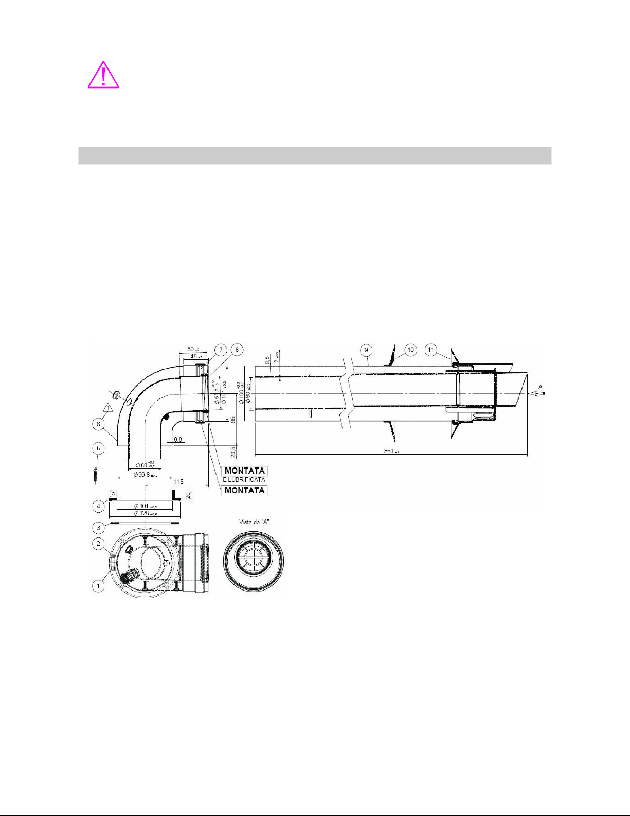
- The duct is then fastened in the elbow.
IN CASE OF CONCENTRIC FLUS, AIR AND FLUE GASES DUCTS
MUST HAVE MAXIMUM 3m IN LENGTH (WITHOUT THE FIRST ELBOW).
IN CASE OF TWIN FLUE,AIR AND FLUE GASES DUCTS MUST HAVE
MAXIMUM 4m LENGTH (WITHOUT THE FIRST ELBOW).
Consist of an elbow, the flue gases duct, the air duct and afferent
gaskets.
The coupling is peformed as follows:
- All gaskets are mounted in their proper places
- The elbow is fastened on the upper cover of the pressurized chamber
using 4 screws, ensuring the gasket between elbow and cover is properly placed
17
CONCENTRIC FLUE SYSTEM (figure 2)
The coaxial ducts must pass through the wall using a pipe with an inner
diameter of 120mm. This pipe is fastened inside the wall and its length must be
established according to the wall thickness. The gaskets between wall and ducts
are mounted at the both ends of the passing pipe.
2 screw M5X25
3, 7, 8 - rubber gasket
4 plastic flange
5 screw 3,9x19mm
6 - flue elbow 900
9 - air duct 100mm/3.93 in
- flue duct 60mm/2,36 in
10, 11 - ornamental wall gaskets
Figure no. 2
Components:
Page 20
IT IS COMPULSORY FOR THE AIR AND FLUE GASES DUCTS TO
HAVE AN ASCENDING SLOPE OF 3% (APPROXIMATELY 2°) IN ORDER TO
FORCE THE CONDENSATE TO FLOW BACK TOWARD THE COMBUSTION
CHAMBER.
A90 degree flue elbow reduces the total duct length by 0,5 m.
Under no circumstances the flue length (including allowances for
extra bends) must not exceed 3m.
18
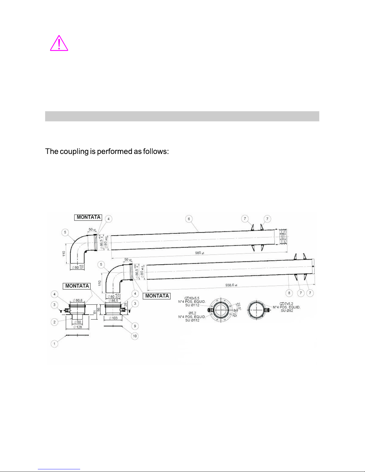
Consist of two exhausting ducts of Ø80mm in diameter and two elbows
(for air duct and for flue gases duct) and the afferent gaskets.
-All gaskets are mounted in their proper places.
- The elbows are fastened on the upper cover of the pressurized chamber
using 4 screws, ensuring the gasket between elbow and cover is properly placed.
- The ducts are then fastened in the elbows.
- The air and flue gases ducts must pass through the wall using pipes
with an inner diameter of 80mm.
TWIN FLUE SYSTEM (figure 3)
Figure no. 3
1, 10 - gasket
2, 9 - flue duct adaptor Ø80
5 - flue elbow 90 Ø80 mm/ 3,15 in
4 plastic terminal Ø80 mm/ 3,15 in
6 - air and flue duct Ø80mm/3,15 in
7 - wall ornament gasket
3 - screws 3,9X9,5mm
0
Page 21
IT IS COMPULSORY FOR THE AIR AND FLUE GASES DUCTS TO
HAVE A SLOPE OF 3% (APPROXIMATELY 2°) DESCENDING,
RESPECTIVELYASCENDING.
A90 FLUE ELBOW REDUCES THE TOTALDUCT LENGTH BY 0,5m.
UNDER NO CIRCUMSTANCES MUST THE LENGTH (INCLUDING
ALLOWANCES FOR EXTRA BENDS) EXCEED 5m.
0
19
The condensate resulted from the water contained in the burning gases is
drained through a pipe specially designed for this purpose. The condensate must
not be drained unless a neutralization process is performed, because the
condensate is acid (with a typical pH in the range 3.8 ÷ 5.4). The materials used in
the construction of the primary heat exchanger and flue duct system cannot be the
same as those used in conventional boilers (i.e. cooper or aluminum) because of
the acidity of the condensate. Therefore, the primary heat exchanger is made of
stainless steel and the flue ducts are made of special plastic materials.
At boiler installation, half liter of water must be introduced into the flue duct in order
to fill the condensate trap. This eliminates the danger that fumes might escape
through the flue duct into the room and cause poisoning.
In order to avoid water stagnation inside the condensate drainage system, the
pipes must be continuously descending, especially if the drainage system might
be exposed to freezing.
The condensate drainage must comply with the current standards and installation
codes available in the destination country.
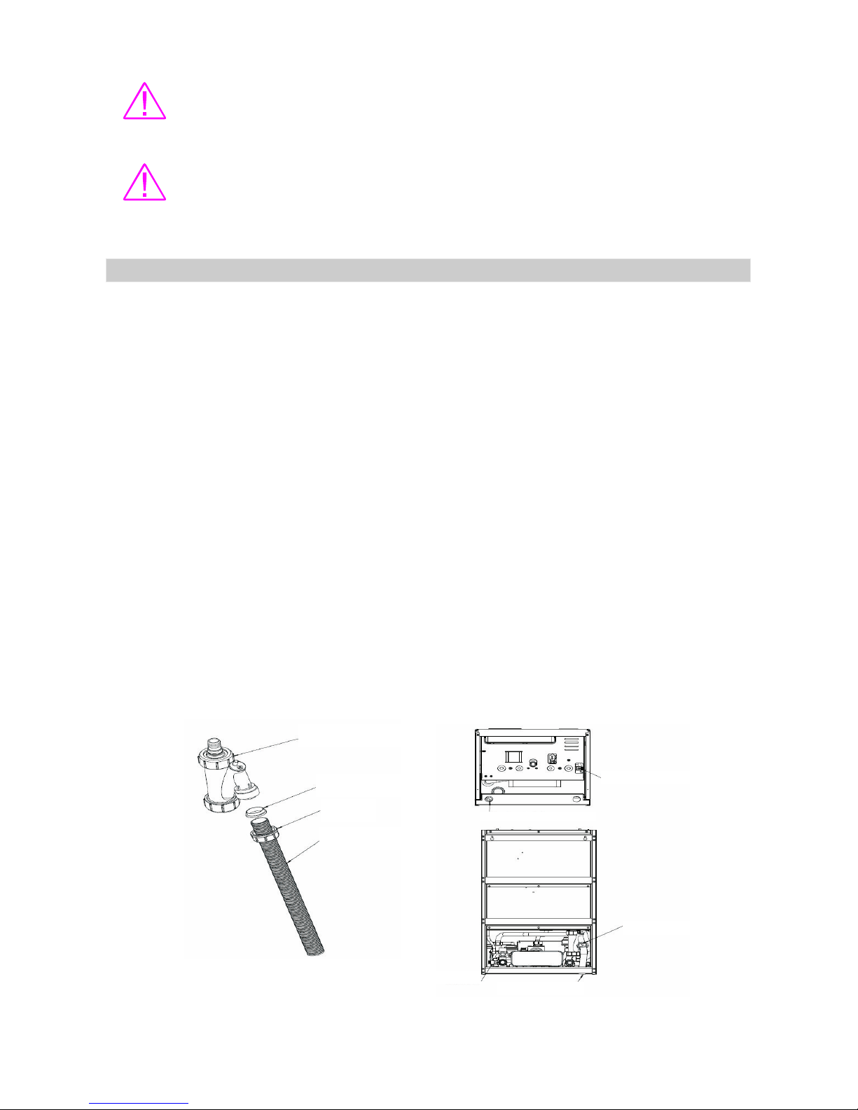
Condensate drain hose mounting instructions (see figure 4):
- unscrew the nut
- replace existing hose with another PVC flexibile hose, with desire length
- mount the gasket on hose
- screw in the nut together with hose and gasket.
Figure no.4
3.4 CONDENSATE DRAINAGE - see figure 4
Gasket
Drain valve
Drain valve
Condensate drain
PVC hose,
Dext.=25mm
Nut
Condensate siphone
Condensate siphone
Condensate
siphone
Page 22

20
The putting into service shall be performed only by an authorized personnel.
The personnel that ensure putting into service shall agree with the conditions
specified in the Technical Manual. These are necessary for warranty
awarding:
- The boiler must be correctly installed (conforming to local laws) and the
proper draught must be ensured.
- The electrical power supply must be compliant with the next parameters:
230V, 50Hz and 130W minimum.
- The gas supply system must be built by authorized personnel conforming
to local laws.
- The CH and DHW installation must be built by authorized personnel. The
minimum distance to the nearest draining point is 6m.
- The putting into service shall be performed only by personnel authorized
and certified by KOBER LTDTurturesti, Vaduri Branch.
- The authorized personnel may decline the responsibility if the conditions
stated above are not met.
The conditions stated above are compulsory. The authorized personnel shall
specify all malfunctions that obstruct the proper operation according to the
parameters indicated in the Technical Manual. The boiler will start only if all
elements are optimally functioning.
The non-compliance with these conditions obstructs the putting into
service at the established date. In this case, the end-user will pay all taxes to the
authorized personnel for putting into service.
The putting into service and maintenance of the “MOTAN” boilers
during the warranty period must be performed only by personnel authorized
(according to local laws) and certified by KOBER LTD Turturesti, Vaduri Branch.
1. The boiler must be placed in areas with ventilation according to the current
standards regarding boilers mounting and putting into service.
2. The heating installation must be completely filled with water and correctly
vented; the water pressure must be of minimum 1 bar.
3. The gas supply system must be equipped with a pressure controller that
ensures constant pressure / constant gas rate in accordance with the
specifications from the Technical Manual. Check the gas supply system
(especially the joints) for leakages.
4. The gas consumption and maximum / minimum pressures on gas valve inlet and
outlet must be adjusted in accordance to the Technical Manual.
5. The electrical power system must be compliant with the parameters specified in
the Technical Manual.
1.
2.
3.
It is compulsory to perform the following checks:
4. PUTTING INTO SERVICE
Page 23

21
The commissioning shall be performed only by an authorized personnel and
certified by KOBER LTDTurturesti, Vaduri Branch.
The personnel that ensure commissioning shall agree with the conditions
specified in the Technical Manual. These are necessary for warranty
awarding:
a. The boiler must be correctly installed (conforming to local laws) and
the proper draught must be ensured.
b. The electrical power supply must be compliant with the next
parameters: 230V,50Hz and 130W minimum.
c. The gas supply system must be built by authorized personnel
conforming to local laws.
d. The CH and DHW installation must be built by authorized
personnel. The minimum distance to the nearest draining point is
6m.
e. The commissioning shall be performed only by personnel
authorized.
f. The authorized personnel may decline the responsibility if the
conditions stated above are not met.
The conditions stated above are compulsory. The authorized personnel shall
specify all malfunctions that obstruct the proper operation according to the
parameters indicated in the Technical Manual or Service Manual. The boiler will
start only if all elements are optimally functioning.
The non-compliance with these conditions obstructs the putting into service
at the established date. In this case, the end-user will pay all taxes to the
authorized personnel for putting into service.
The commissioning and maintenance of the “MOTAN” boilers during the
warranty period must be performed only by personnel authorized (according to
local laws) and certified by KOBER LTD Turturesti, Vaduri Branch.
1. provide power supply to the boiler
2. fill the central heating system
3. connect the room thermostat and external probe
4. verify the gas type
5. measure the static pressure
6. measure the dynamic pressure
7. initial lighting
8. testing heating system
9. instruct the user
1.
2.
3.
The steps of commissioning
5. COMMISSIONING
Page 24

22
Verify with a multimeter: the polarity, the grounding, grounding and short
circuit resistance. The gas boiler must be connected at monophase network by
230V/50Hz through 5Afast-blowing fuse, with grounding.
The electrical supply must be grounded and must keep into accout the
semantic of colour: brown phase; blue null, green yellow = grounding.
Connect double-pole switch in plug, taking care that the phase to
correspond with brown wiring of power supply cable.
It is reccomended that the installation filling up to be done with softened
water.
The primary system is filled up with water until the pressure
achieves 1.5 bar +/- 0.5, 21,49+/-7,1 p.s.i. The water heating bring to at thermal
distension which modify the pressure.
Filling up the instalation requires to follow next steps:
First, open the domestic hotwater tap and then the central heating tap.
Fill up the heating system ultil the requested pressure is achieved.
Verify the tightiness of the entire system by cecking for potential leakages and
solve eventual problems; after this, repeat the steps presented above.
The airing of the system is acheived using deairators from instalation and using
boiler pump airing plug by repetitive starting the pump with gas valve closed. After
these operations, the system is filled up again until the nominal pressure is
acheived.
The instalation pressure is verifyed.
Note:
IT IS MANDATORY TO INSTALL AN IMPURITY FILTER ON THE
PRIMARYHEATING SYSTEM (RETURN).
IT IS FORBIDDEN TO USE AN EMPTY BOILER OR A BOILER
PARTIALLY FILLED WITH WATER .
USING AN EMPTY BOILER OR A BOILER PARTIALLY FILLED
WITH WATER MAY LEAD TO EXPLOSIONS.
Appliance with Filling Tap
·
·
·
·
·
5.1 VERIFY THE POWER SUPPLY TO THE BOILER
5.2 THE FILLING UP
Page 25
23
ROOM THERMOSTAT
EXTERNAL PROBE
The fitting of a room thermostat is made on one of inside walls. Don't mount near
heat sources, in front of sun, near cold water pipework/ hot water pipework or near
places with air current.
Room thermostat and external probe is used for optimize the electrical
and natural gas consumption and for a superior comfort.
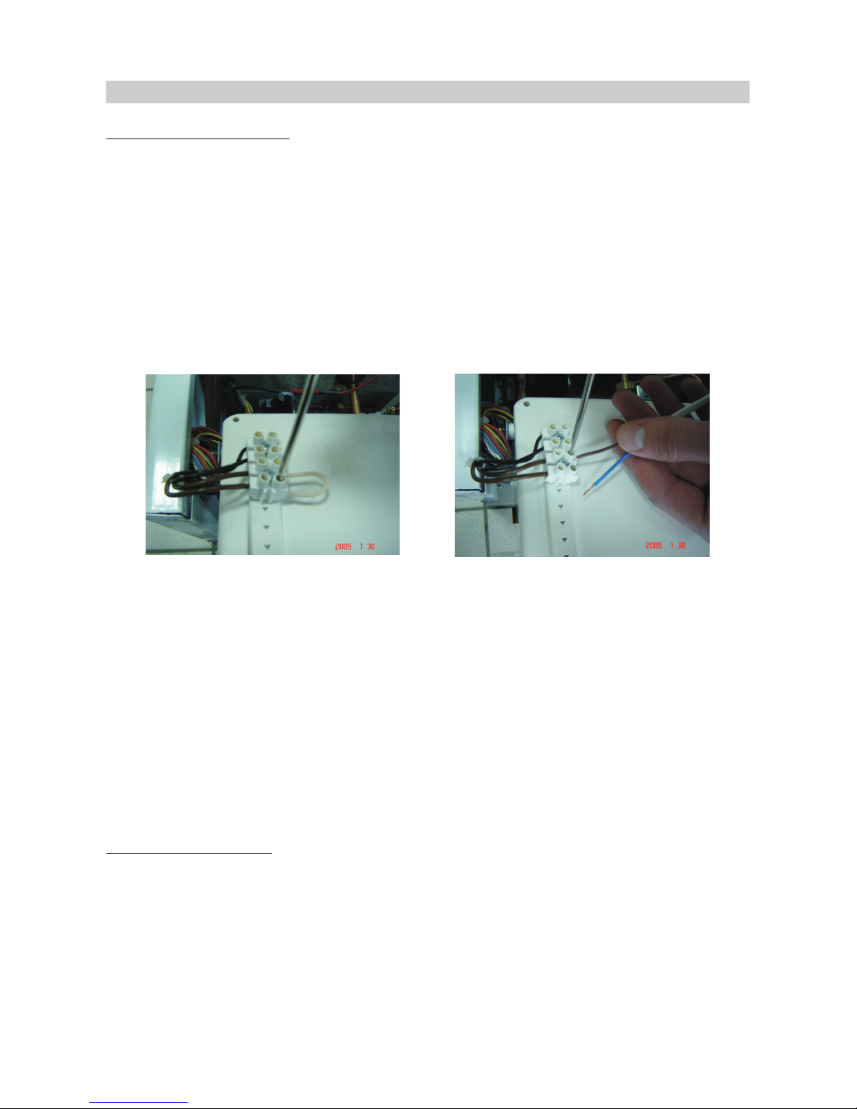
Ensure the following operations are carried out:
dismantle the boiler's frontal panel;
- unscrew the screw securing the lid and open up on hinges for making
the coupling;
- identify the room thermostat' s coupling connector (bridge wiring) and
the external probe's coupling connector (black wiring);
in case of room thermostat, take off the connection electrical cable (the
bridge) between the two connector's terminals;
- uninsulate the two wiring of bifilar cable which make the connection with
room thermostat or external probe;
- Introduce the bifilar cable in the connectors through screwing;
- The bifilar cable's diameter is 0,5 mm and is from copper litz wire.
The placing of room thermostat is made as so to assure a maximum
comfort.
We recommend to place the room thermostat at a height of 1,2 m, in the
coldest room.
By using an external probe, the “climatic compensation” function may be
activated (only be the autorized service person). In this case, the outgoing water
temperature is adjusted according to the outside climatic conditions, ensuring a
high comfort and energy saving when boiler operates in “Winter” season (AT
mode). Thus, on outside temperature increase, the outgoing water temperature is
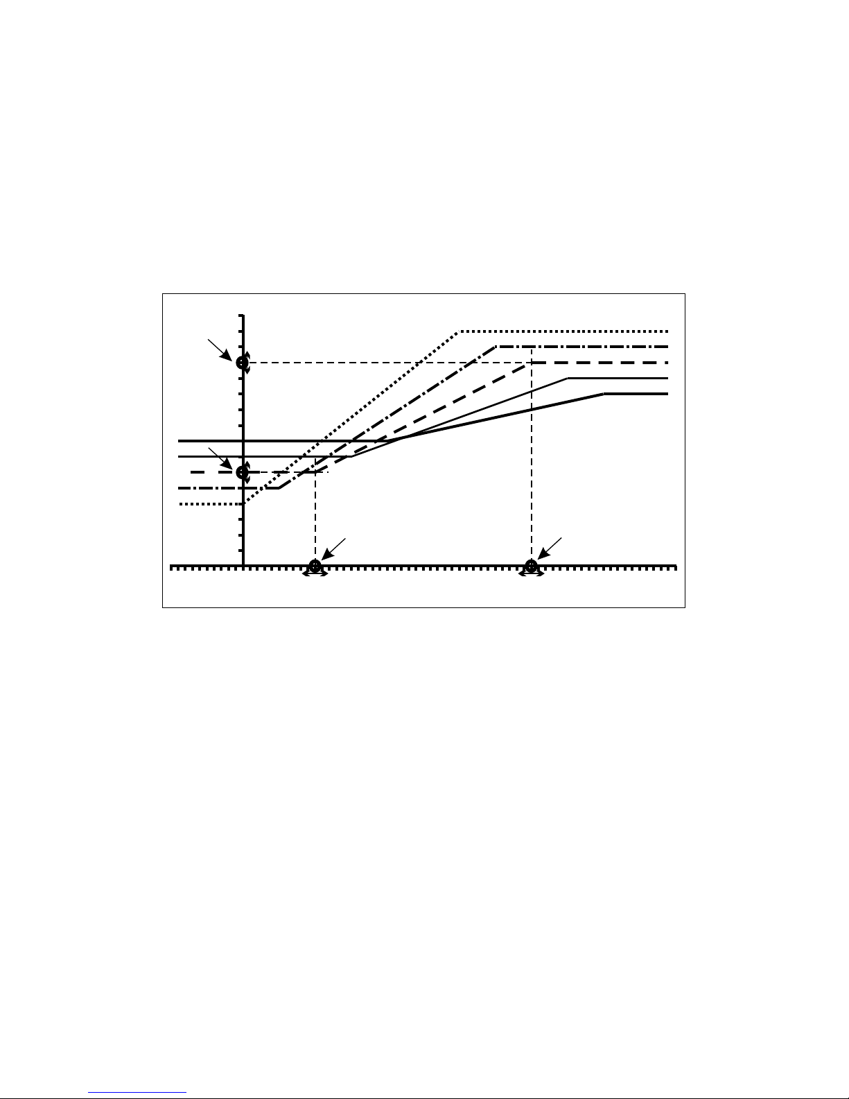
decreased according to a “compensation curve” (see figure 5).
-
-
Picture no.5
2
5.3 CONNECT AN ROOM THERMOSTAT AND AN EXTERNAL PROBE
Page 26
24
The positions of points A, B, C and D, which define this curve, are determined as
follows:
- The position of point A: is determined by the value of system outgoing
water set-point;
- The position of point B: is determined by the value of the minimum CH set
point; in the case of MKDens boiler, this value is:
- 30°C for high temperature CH system (radiators);
- 15°C for low temperature CH system (under floor heating);
- The position of point C: is determined by the autorized service person;
- The position of point D: is determined by the autorized service person.
As an example, the positions of points A, B, C and D from fig. 6 are established by
the following temperatures:
- A: 75°C
- B: 40°C
- C: 20°C
- D: -10°C
The correspondent compensation curve shows:
- If the external probe temperature is lower than -10°C, the value of
system outgoing water set-point will be 75°C.
- If the external probe temperature is higher than 20°C, the value of
system outgoing water set-point will be 40°C.
- If the external probe temperature is 0°C, the value of system outgoing
water set-point will be (about) 63°C.
Figure no. 5. Climatic compensation curve
40
10
15
20
25
30
35
40
45
50
55
60
65
70
75
80
85
90
35 30 25 20 15 10 5 0 -5 -10 -15 -20 -25 -30
A
B
D
C
External probe ( C)°
Sm probe setpoint ( C)°
Page 27

25
Request from the combustible supplier the gas type and Wobe coefficient.
Superior/ Inferior Wobbe coefficient is equal to the gross calorific value of the gas
in British thermal units per cubic foot at standard temperature and pressure divided
by the square root of the specific gravity of the gas.
The gas boiler is settled by producer for G20 type.
The static and dynamic measurement of gas valve inlet means some
preceding operations ,as following :
turn off the gas tap;
take off the front cover for heaving acces to gas valve;
turn on the fixing screw of electronic plastic box and open it up for can
make the measurement.
The static pressure measurement can be achieved as following :
turn-on the screw of test point ,using a 1x5 mm flat top screw-drive
connect the manometer's tube on the test point;
turn-on the gas tap;
read the pressure value from manometer's display.
The range of minimal and maximum value of static pressure for using GN,
must be 25...30 mbar.
After finalising the measurement of static pressure turn on the boiler and
read the pressure value from manometer's display.
The range of minimal and maximum value of dynamic pressure for using
GN , must be 20...25 mbar . : if the dynamic pressure is
not in this range, than the performances of combustion will be not good .
turn-off the boiler using the “STAND-BY” switch;
turn-off the gas tap;
get-out the manometer's tube from test point;
- turn-on the screw of test point.
Before and after making of installation, must be checked the
concentration of CO (carbon monoxide), according with the valid legislation
and normative.
VERY IMPORTANT
Verify the connection's tightness on gas valve pressure test point.
-
-
-
-
-
-
-
-
-
-
Obturate the flue system.
The air pressostat will observe the gas exhausting absence and on the
display appear FO 02 error.
The boiler will start to operate when the flue system obturation disappear.
5.4 VERIFY THE GAS TYPE
5.5 THE MEASUREMENT OF STATIC PRESSURE
5.6 THE MEASUREMENT OF DYNAMIC PRESSURE
5.7 VERIFY THE EXHAUST SYSTEM
Page 28

26
DO NOT operate the boiler without water.
Check that all external controls are calling for heat.
Press the on/off button for start the boiler. Press the winter/summer
button for start on Central Heating mode.
Set the Central Heating temperature and the Domestic Hot Water
temperature at maximum value.
The lighting procedure of the boiler is fully automated.
The digital display will show water temperature in central heating
demand. The appliance will enter a self checking routine then the fan should
start and the ignition will commence.
If the burner fails to light the fan will stop. Initially this may be due to air
in the gas supply line (with gas tap off). The boiler will automatically have three
attempts at ignition.
If the boiler fails to ignite the display will show FO 02.
Press the reset button for repeat the ignition sequence.
Once the system has been purged of air. Set the hot water to the
desire temperature by using and open the hot water tap, the diverter valve
motor will move to hot water supply and the display will read domestic hot water
temperature.
Check that hot water is available and then close the hot water tap. Set
the central heating water temperature to the desire temperature by using and
continue to operate in central heating until the user controls are satisfied or
there is another demand made.
The User must be advised (and demonstrated if necessary) of the
following important points:
How to light and turn off the boiler in safety conditions through the verify of the
following components:
the main supply and polarity respecting.
gas supply.
central heating system loading.
after central heating system loading, the filling valve must be closed.
the pressure of central heating system must be in the range1-
2bar/14,33-28,66 p.s.i.. The pressure is displayed on the control .
The taps on the DHW system must be open.
The gas boiler's operation and the errors which can appear. Explain the
switches meaning.
The autorized person must tell the user about the sealed system pressure.
The user must call at least once per year the authorized service engineer for
gas boiler's verify.
1.
panel
2.
3.
4.
-
-
-
-
-
-
5.8 INITIAL LIGHTING
5.9 INSTRUCT THE USER
Page 29
27
5.
6.
The Service Mode must be accessed only by an authorized person
for the boiler installation or service. The end-user can access only the User
Mode.
The autorized person must explain to the user about the frost protection.
Explain the user that if he is leaving home, in cold season, for a longer period of
time, it is recommended to empty the heating circuit and avoid installation
freezing.
The autorized person must hand to the user the technical instructions.
At the end, the user must sign a commissioning's paper, which certify that
the user learn the user information.
The authorized service engineer have the right to refuse the
commissioning in case there is a screw loose somewhere.
The authorized service engineer which make the commissioning is not
obliged to correct the errors of heating system (without gas boiler). The authorized
service man must verify that the heating system (without gas boiler) correspond
functionally and constructive with the gas boiler.
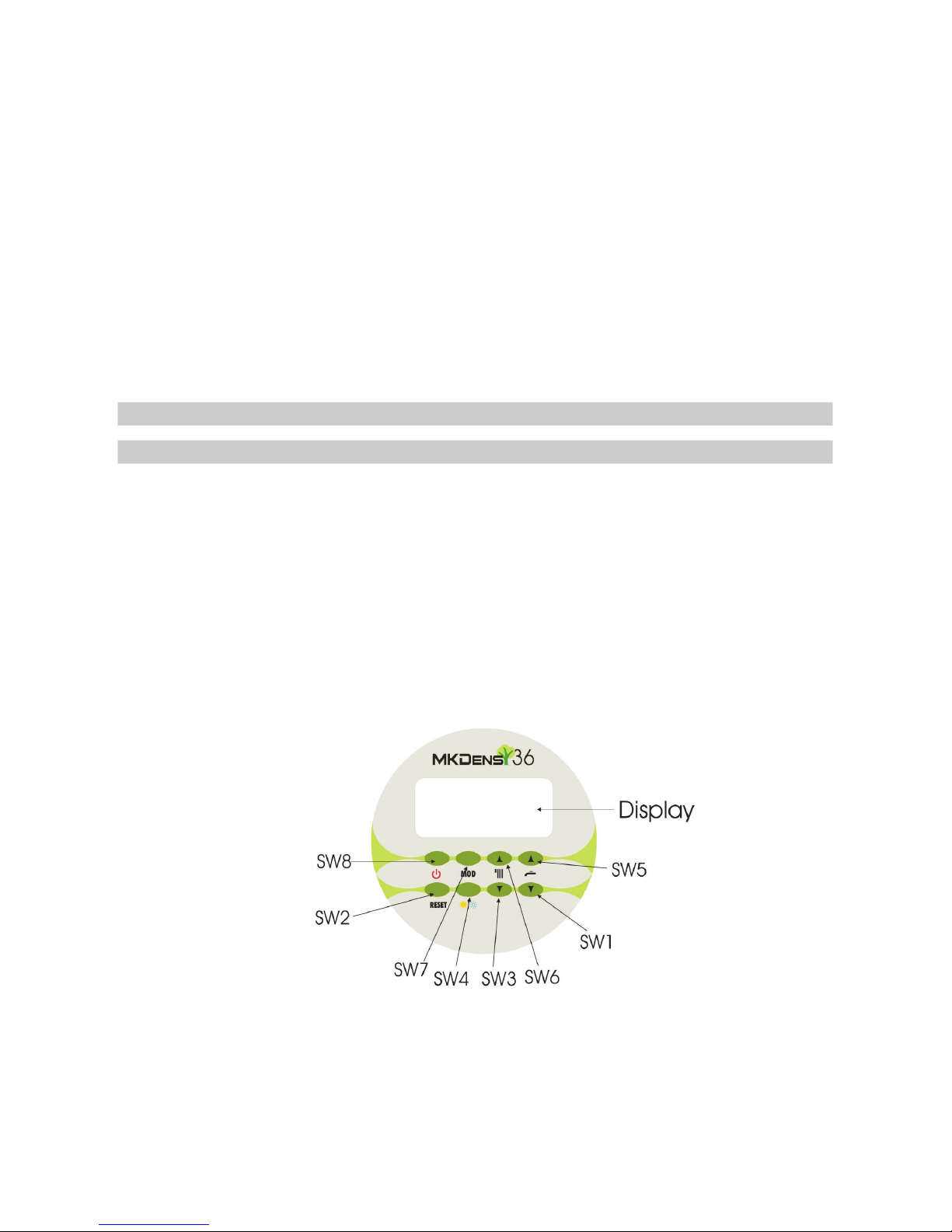
The control panel (Figure 6) has 8 keys and a LCD display (Figure 7) and
allows the configuration of the boiler (operation performed only by an authorized
person, when the boiler is installed or during the service operations). It also allows
the interactions between the user and the boiler, display of the measurements from
the sensors and the error codes signaling boiler faults.
Two operating modes are available:
Service Mode
User Mode
Figure no.6. The control panel
·
·
6. USAGE INSTRUCTIONS FOR THE END USER
6.1 CONTROL PANEL
Page 30
The control panel keys functions in mode are presented in table 1.
Table 1
User
28
KEY
S W 6
S W 5
S W 1
S W 7
S W 4
S W 8
S W 2
FUNCTION
(+) CH: On the first pressing, the set value for the outgoing water
temperature is displayed. Next pressings of the key lead to the
increasing of this set value. Symbol 8 blinks during these
operations.
(+) DHW: On the first pressing, the set value for DHW temperature is
displayed. Next pressings of the key lead to the increasing of this
set value. Symbol 7 blinks during these operations.
(-) DHW: On the first pressing, the set value for DHW temperature
is displayed. Next pressings of the key lead to the decreasing of
this set value. Symbol 7 blinks during these operations.
MOD: All the probe values are cyclically displayed (see table 4) by
repeatedly pressing this key. After 10 seconds from the last
pressing of the button, the unit displays back the outgoing water
temperature.
“Summer” / “Winter” season selection. The symbol 2 is activated
in “Summer” season and symbol 3 is activated in “Winter” season
(see fig. 7 and table 1).
Board switching on and off (if pressed for more than 1 second).
Excepting symbol 1, LCD is completely deactivated when the boiler
is in OFF state. When the boiler is turned ON, the symbol 1 is
deactivated and LCD displays all the symbols corresponding to the
active functions.
Boiler reset from non-volatile lockout (if pressed for one second and
then released).
S W 3
(-) CH: On the first pressing, the set value for the outgoing water
temperature is displayed. Next pressings of the key lead to the
decreasing of this set value. Symbol 8 blinks during these
operations.
Page 31
29
Figure no. 7. The LCD display
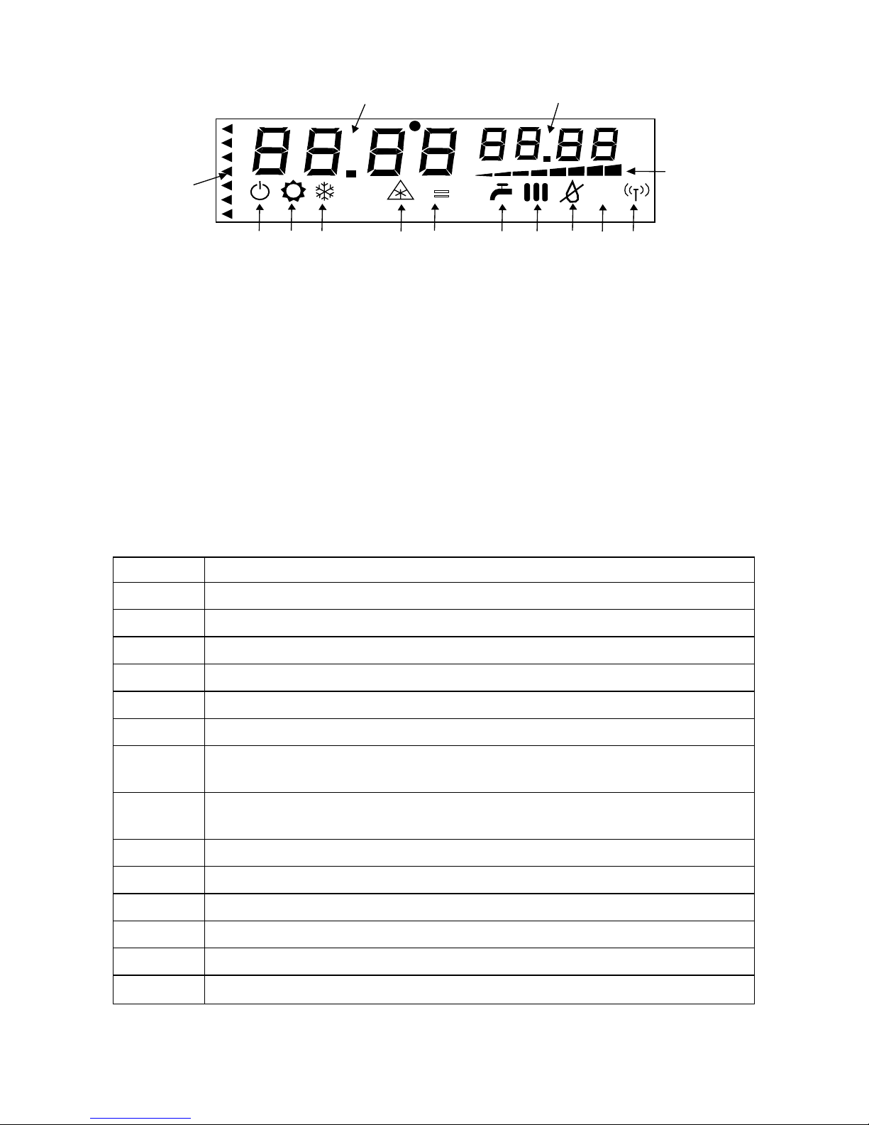
When the Boiler Control Unit (BCU) is powered on, the user wait 25
seconds before any commands can be processed. During this period, the symbol
“---” is permanently being dispayed and symbol 11 is blinking.
After 25 seconds on the LCD display appear the symbols indicated in
figure no.7. In the following paragraphs we discribe this symbols.
The symbols 1 through 12 of the LCD display from the control panel
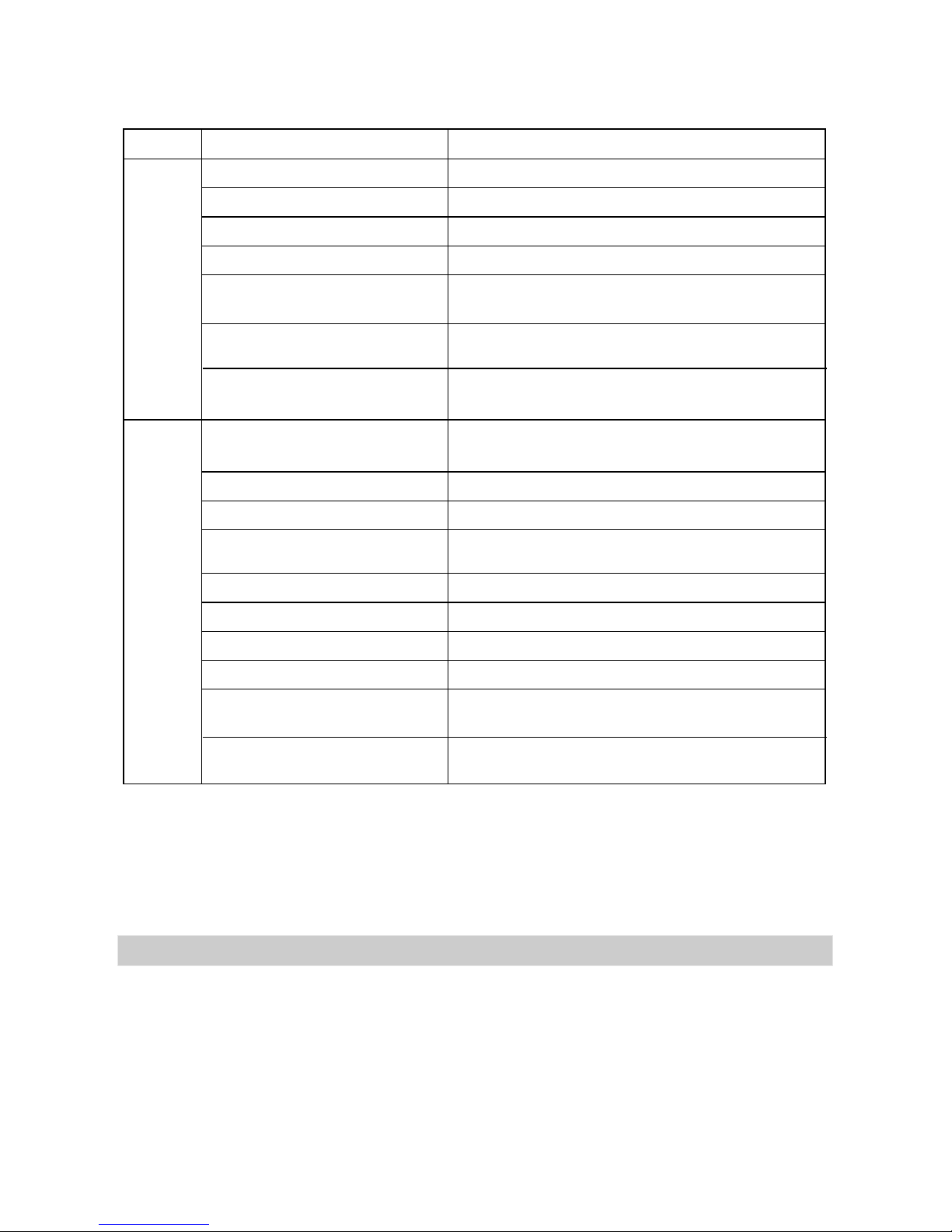
have the meanings described in the Table 2. The symbols 13 and 14 display the
information presented in Table 3.
Table 2
The end user can access this operating mode only.
SYMBOL
1
2
3
4
5
6
7
8
9
10
11
12
13
14
DESCRIPTION
Boiler in “OFF” state
Boiler in “SUMMER” season
Boiler in “WINTER” season
Antifreeze cycle active
“Service” mode (blinking)
Parameters setting error
Domestic Hot Water request / Domestic Hot Water set-point
change (blinking)
Central Heating request / Central Heating set-point
change (blinking)
Flame detected / not detected (boiler in “lockout” state)
Error detected
Not used
Fan modulation bar
See table 2
See table 2
6
1
2
3
4
5
7
8
9
10
11
12
13
14
%
%
=
Page 32
30
Table 3
Each temperature that can be set in User mode has an associated range:
CH: - radiators: 30-80 °C
- pavement: 15-40 °C
DHW: 30-60 °C
Ambient temperature: 35-45 °C
When the Boiler Control Unit (BCU) is powered on, the user must wait
25 seconds before any commands can be processed. During this period, the
symbol “----“ is permanently being displayed and symbol 11 is blinking.
The boiler is : its operation is supervised and controlled by the
BCU and the other constitutive devices of the control system, including the
optional devices (room thermostat or remote chrono-thermostat).
·
·
·
fully automatic
AREA
13
14
EVENT
DESCRIPTION
Standby / normal operation System water pressure expressed in bar + “b”
“Setp”
“Off”
CH set-point (°C)
“On”
“H”
“-St-”
“L”
“-St-”
“Setp”
“FO” + error code (see table 4)
“In” + information index (see table1)
Primary system outgoing water probe
temperature (°C)
Domestic Hot Water probe temperature (°C)
Pressing SW6 / SW3
Switching off the boiler
Pressing Sw6 / SW3
Pressing SW5 / SW1
Error
Pressing SW7
DHW set-point (°C)
“Err”
Information value (see table 1)
Turning on the boiler
Pressing SW5 / SW1
Error
Pressing SW7
Stand-by
Domestic Hot Water request
Chimney-sweep at the
maximum power
Chimney-sweep at the
maximum power
Chimney-sweep at the
minimum power
Chimney-sweep at the
minimum power
6.1.1 BOILER CONTROL UNIT - POWER ON
Page 33

31
During winter, in case of power off or other possible situations when
temperature can drop below the freezing point (0°C) for more than 2-3 hours, the
water from both CH and DHW circuits must be drained. The boiler will be
disconnected from both power and gas supply networks.
The boiler operates in this mode only when “Winter” season is selected. If
the room thermostat is present, this device commands the boiler turning on / off. If
the room thermostat is not present, the boiler will carry out an ignition cycle when
the outgoing water temperature will be lower than the set temperature with 5°C (in
the case of CH system with radiators) or 2°C (in the case of pavement CH
installation). After ignition, the flame modulation will begin; the BCU tries to deliver
the outgoing water at the set-point temperature. If the outgoing water temperature
is 5°C higher than the set temperature selected by the user (or 2°C in the case of
pavement CH installation) the boiler will switch off. Re-ignition occurs as soon as
the water temperature drops 5°C (2°C) below the set value.
The boiler operates in this mode in both seasons (“Summer” or “Winter”)
when domestic water flow is detected.
Domestic hot water requests have priority over central heating. Therefore,
when the boiler operates in CH mode (in “Winter” season) and a DHW request is
detected, the boiler will be switched in DHW mode. When the DHW request stops,
the boiler returns to CH mode.
When a DHW request is detected (by the flowmeter), the BCU starts the
ignition and the system tries to deliver hot water at the set temperature.
If “Summer” season is selected, the boiler will operate only in DHW mode
even if the ambient temperature or outgoing water temperature recommends
operation in CH mode.
The system water pressure must be periodically checked by the user.This
pressure is displayed on LCD (see figure 7 , position 13) and must be of 1-2 bar.
If pressure drops below 0.8bar, the error code will be displayed and
boiler stops. If pressure rises over 3 bar, the safety valve will be opened.
By using an external probe, the “climatic compensation” function may be
activated (only be the autorized service person). In this case, the outgoing water
temperature is adjusted according to the outside climatic conditions, ensuring a
high comfort and energy saving when boiler operates in “Winter” season (AT
mode). Thus, on outside temperature increase, the outgoing water temperature id
decreased according to a “compensation curve” (see figure 5 chapter 5.3).
FO 01
6.1.2 “CENTRAL HEATING” MODE (symbol 8 ON)
6.1.3 “DOMESTIC HOT WATER” MODE (symbol 7 ON)
6.1.4 SYSTEM WATER PRESSURE CHECKING
6.1.5 ADDITIONAL FACILITIES
Page 34

In case the end user establishes that the appliance has an abnormal
running, if the error codes keep displaying or if the appliance manifestations can
not be understood, he has the obligation of shutting-down the boiler as soon as
possible and in maximum safety conditions. The user must perform the following
operations:
Press STAND BY (SW8 button from figure “Control Panel”) and the boiler
shuts down;
Disconnect the boiler from the electric power supply circuit by unplugging;
Disconnect the gas supply circuit by switching off the gas valves;
Interrupt the DHW and the DCW (domestic cold water) circulation by
switching on the gas valves corresponding to these circuits.
After boiler shutting down in maximum safety conditions, the user must
call the service authorized provider.
Each time the boiler is shutting down (in CH mode), the pump keeps running for a
short period of time in order to lower the water temperature in the main heat
exchanger; in this way, water overheating is avoided.
Each time the boiler is shutting down, the fan keeps running for a short period in
order to evacuate the humid vapors and prevent moisture from invading or
damaging the fan driving circuit.
If the boiler does not effect any cycle during a 24 h period, the pump will start
running for a few seconds to avoid blocking caused by the non-running.
On each pump shutting down, the three-way valve is activated for one second
and then it reverts to the initial position.
When the outgoing water temperature drops to 6°C, the burner is activated and
boiler starts to operate on minimum power in CH mode. The boiler stops
(antifreeze function is disabled) when the outgoing water temperature reaches
6°C.
·
·
·
·
1. Pump overrun
2. Fan post-purge
2. Pump anti-blocking function
3. Three-way valve anti-blocking function
4. Antifreeze function (symbol 4 ON)
6.1.6 THE BOILER SHUTTING-DOWN IN SAFETY CONDITIONS
6.2 FUNCTIONS CONCERNING BOILER SAFETY
32
Page 35
33
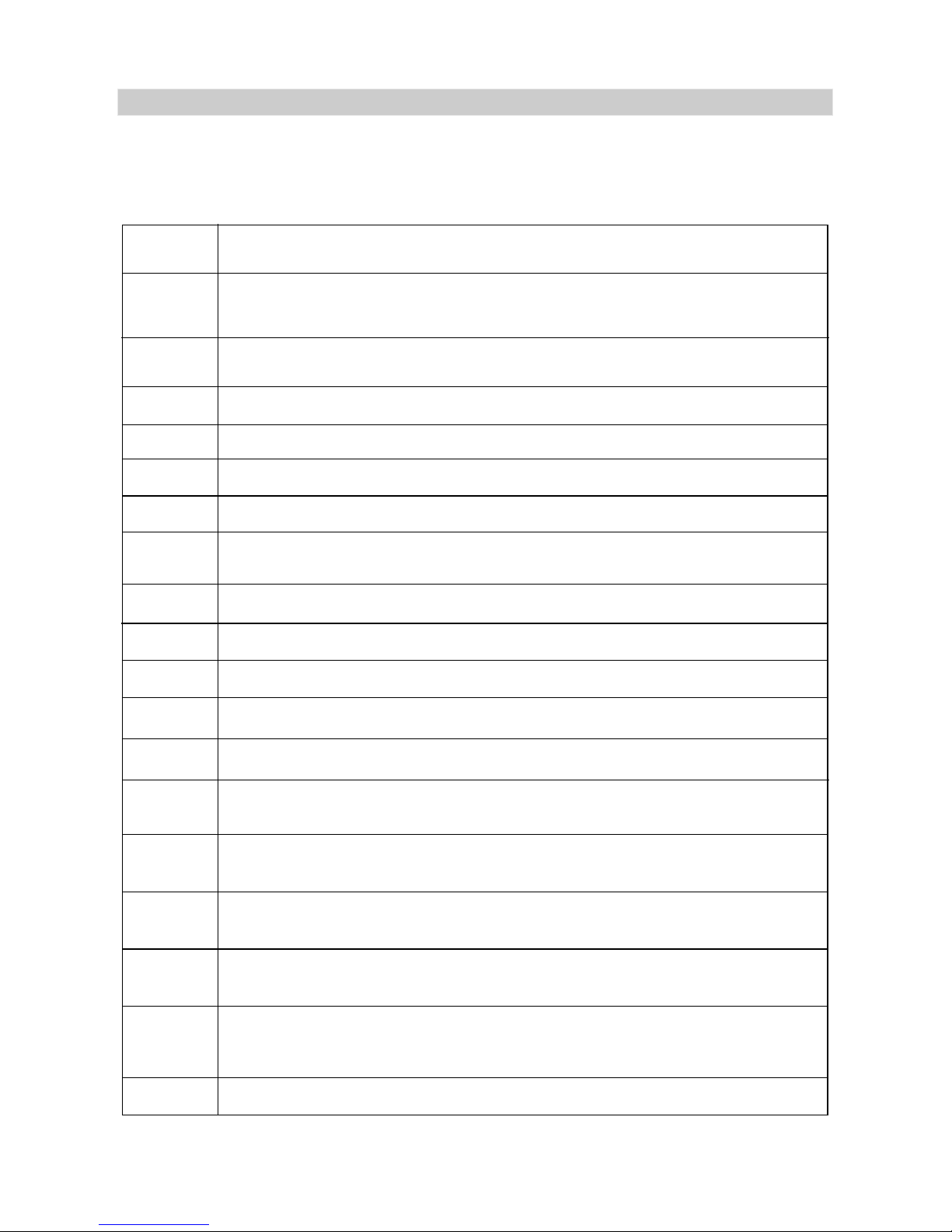
The information sent by sensors and safety devices to the BCU is used in
the detection of malfunctions. In these cases, the error codes are displayed on the
LCD. These error codes are presented in Table 4.
Table 4
ERROR
CODE
FO 01
FO 02
FO 03
FO 12
FO 13
FO 14
FO 15
FO 04
FO 05
FO 07
FO 11
FO 08
FO 17
FO 18
FO 19
FO 20
FO 21
FO 22
DESCRIPTION
The heating system has a low water pressure (below 0,8 bar) or the pump does not
work properly. The user must press SW2 (RESET) key. If the error is present after a
few resets of BCU, the user shuts down the boiler in safety conditions and calls the
!service provider
Flame failure.The user must press SW2 (RESET) key. If the error is present after a few
resets of BCU, the user shuts down the boiler in safety conditions and calls the
!service provider
The electric signal from the primary temperature probe (CH) is missing. The user shuts
down the boiler in safety conditions and calls the !service provider
The electric signal from the secondary temperature probe (CH) is missing.The user
shuts down the boiler in safety conditions and calls the !service provider
The electric signal from the external temperature probe (CH) is missing. The user shuts
down the boiler in safety conditions and calls the !service provider
The electric signal from the combustion detection probe (CH) is missing.The user shuts
down the boiler in safety conditions and calls the !service provider
The electric signal from the floor temperature probe (CH) is missing. The user shuts
down the boiler in safety conditions and calls the !service provider !
The electric signal from the temperature probe (DHW) is missing.The user shuts down
the boiler in safety conditions and calls the service provider!
The electric signal from the fan is missing.The user shuts down the boiler in safety
conditions and calls the !service provider
Fake flame resulted from bad ignition.
The user shuts down the boiler in safety conditions and calls the !service provider
Fan speed errors. The user shuts down the boiler in safety conditions and calls the
!service provider
The boiler shuts down due to safety thermostat. The user must press SW2 (RESET)
key. If the error is present after a few resets of BCU, the user shuts down the boiler in
safety conditions and calls the !service provider
The temperature of the combustion products is above the limit (90°C). The user must
press SW2 (RESET) key. If the error is present after a few resets of BCU, the user
shuts down the boiler in safety conditions and calls the !service provider
The temperature recorded from the primary CH probe is above the limit. The user must
press SW2 (RESET) key. If the error is present after a few resets of BCU, the user
shuts down the boiler in safety conditions and calls the !service provider
The temperature recorded from the DHW probe is above the limit.The Sw2 (RESET)
key must be pressed by the user. If the error is present after a few resets of BCU, the
user shuts down the boiler in safety conditions and calls the !service provider
The temperature recorded from the secondary CH probe is above the limit. The SW2 (RESET)
key must be pressed by the user. If the error is present after a few resets of BCU, the user shuts
down the boiler in safety conditions and calls the !service provider
The difference of the temperature between the primary and the secondary probes is
above the limit. The SW2 (RESET) key must be pressed by the user. If the error is
present after a few resets of BCU, the user shuts down the boiler in safety conditions
and calls the service provider!
Parameters setting error. The user shuts down the boiler in safety conditions and calls
the !service provider
6.3 ERRORS DETECTION
Page 36

34
The User must be advised (and demonstrated if necessary) of the following
important points:
1. How to light and turn off the boiler in safety conditions through the verify of the
following components:
the main supply and polarity respecting;
- gas supply;
- central heating system loading;
- after central heating system loading, the filling valve must be closed;
- the pressure of central heating system must be in the range12bar/14,33-28,66 p.s.i.. The pressure is displayed on the control panel;
- The taps on the DHW system must be open.
2. The gas boiler's operation and the errors which can appear. Explain the
switches meaning.
3. The autorized person must tell the user about the sealed system pressure.
4. The user must call at least once per year the authorized service engineer
for gas boiler's verify.
5. The autorized person must explain to the user about the frost protection.
Explain the user that if he is leaving home, in cold season, for a longer
period of time, it is recommended to empty the heating circuit and avoid
installation freezing.
6. The autorized person must hand to the user the technical instructions.
At the end, the user must sign a commissioning's paper, which certify that the
user learn the user information.
The authorized service engineer have the right to refuse the commissioning
in case there is a screw loose somewhere.
The authorized service engineer which make the commissioning is not
obliged to correct the errors of heating system (without gas boiler). The
authorized service man must verify that the heating system (without gas boiler)
correspond functionally and constructive with the gas boiler
To ensure efficient operation of the boilerit is recommended that is checked
and serviced as necessary at .
The manufacturer recommends that any service work must be carried out by
a licensed technician. It is recommended that the service work to be carried out
before winter time, when the boiler don't operate at maximum capacity.
Ensure the following operations are carried out:
check the operation of burner and clean it if necessary
check the flue terminal and ensure it is not blocked
verify the settings on gas valve
- verify the circulation pump
- verify the air pressostat and the tightness of flue system
- verify the combustion through the analyze of exhaust gases
- ensure that all system connections, fittings and gas connections are sound
- verify electrical supply.
-
-
-
-
regular intervals (minimum once per year)
6.4 DELIVERY THE BOILER TO THE END USER AFTER INSTALLATION
6.5 ROUTINE SERVICING
Page 37

35
The gas boiler's storage is made in dry places and safe by natural phenomena and
chemical materials.
The product have label on the package (packaging label) and on interior part of
frontal lid (data badges).
On the packaging label are written the following dates:
The manufacturer company
The name of the product, type and size
The serial number
CE 0480
Country(ies) of destination
Category of appliance
The appliance types
The gas supply pressure in millibar
Quality Department authority sign
Also, the product have . This
label states the following:
“
Type of gas: GN G20 H subgroup. Gas supply pressure: 20 mbar
The heater may only be installed in a room wich complies with the appropriate
ventilation requirments and wich is separated from living rooms.
Read the tehnical instructions before installing the boiler.
Read the user's instructions before lighting the boiler.”
Each gas boiler must have in the package the following documents:
- Technical manual;
- EC Conformity declaration (is printed on the back of Technical Manual).
The boilers will be packed into the cardboard boxes, protected by boxboard angles.
The boiler will be delivered with all the installed components, less those from the
appliance book.
During the shipment, all the necessary measures must be taken to avoid strokes or
boiler damaging.
The boilers storage is achieved in dry places and protected by the bad weather
and the chemical agents.
STORAGE
MARKING
ATTENTION label on the electronical box
ATTENTION!
DOCUMENTS
PACKING
TRANSPORT
STORAGE
!
!
!
!
!
!
!
!
!
6.6 STORAGE, MARKING, DOCUMENTS, PACKING, TRANSPORT
Page 38

36
KOBER LTD TURTURESTI VADURI BRANCH OFFICE, as manufacturer,
guarantees the boiler good running if the following conditions are provided:
The correct installation and setting by the authorized personnel.
The yearly examinations are achieved on beneficiary demand and at the
expense of the beneficiary, the first year examination is compulsory to
maintain the guarantee for the first three years of usage.
The exchanged components will be warranted for one year. This doesn't
mean that the set guarantee period will prolong for the entire device.
The guarantee period prolongs from the moment the user has claimed the
device breakdown and till the time the device will be putted into service
again.
The heating installation design and execution should be performed by
qualified personnel (if needed).
It is necessary to check and clean the installation before mounting the
boiler in case of an existing installation.
The interventions during the warranty period will be performed only by the
authorized personnel of the manufacturer company.
Any repair by another person except the authorized personnel of the
manufacturer company leads to warranty loss.
The boiler will be used in conformity with the technical instructions “tehnical manual”. Any deviation from these instructions leads to
warranty loss.
All devices are sealed after adjustment with withe, red or black paint.
Please be aware that if any sign of demaged seale will be found this leads
to warranty loss.
the guarantee does not cover the malfunctions that refer to the
responsibility of the utilities providers, also for: inadecvate manipulation
after delevery; improper storage conditions untill putting into service; the
installation and putting into service by the unauthorized personal;
improper mounting conditions (including demages of the appliance
because installation frost).
!
!
!
!
!
!
!
!
!
!
! Attention:
See details in page number 39- 40.
6.7 QUALITY AND GUARANTEE CONDITIONS
Page 39
37
MKDens36 Boiler, type C13SPV36MEF
MKDens25 Boiler, type C14SPV25MEF
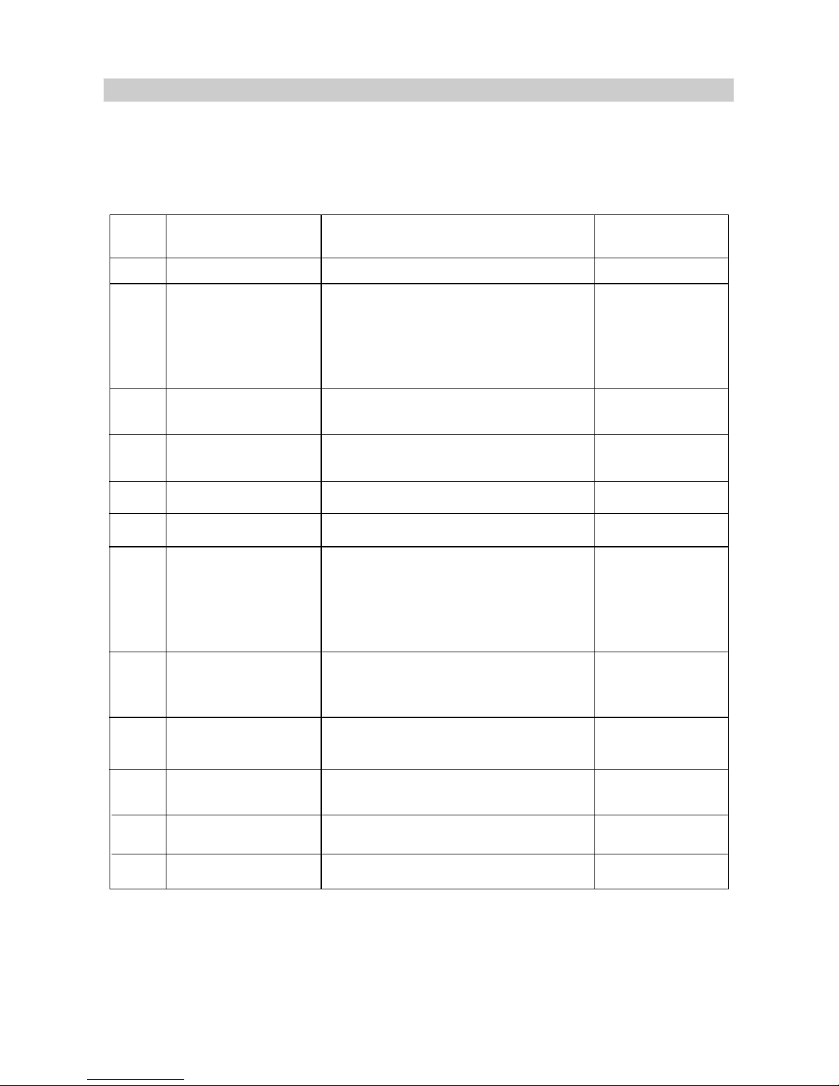
MALFUNCTIONS THAT REFER TO THE MANUFACTURER’S RESPONSABILITY
NO.
1
3
5
4
6
7
8
9
10
11
12
2
COMPONENT
POSSIBLE
ERROR CODE
DESCRIPTION
Pressure sensor
Gas valve
Expansion vessel
Heat
exchanger
Burner
Ignition electrode
and/or ionization
electrode
The control board
(display)
Control Board Unit
(BCU)
Ignition
transformer
Overheating
thermostat
Ventilator
FO 01
FO 02
FO 01
FO 22
-
-
-
-
FO 02
FO 05
Temperature
probes
A defective running
- it does not run or;
- it runs defectively
Pressure losses
Defective
Burner distortions
Parasite spark; there is no spark
between the electrode and the burner
or it loses the spark due to the
defective isolation; there is no flame;
it is flame, but is not flame signal.
You can not operate the wanted
setting any more by pressing.
There is no information displayed.
Malfunction determined by
Control Board Unit.
Defective
Defective
Defective
Broken cables or defective probes:
- CH flow probe (outgoing water)
- CH return probe
- DHW probe
- Flue gases probe
FO 03
FO 12
FO 04
FO 14
FO 07
FO 02
6.8 RESPONSABILITIES DURING THE WARRANTY PERIOD
Page 40

MALFUNCTIONS THAT REFER TO THE RESPONSABILITY OF THE
UTILITIES PROVIDERS
MALFUNCTIONS FOR WHICH THE MANUFACTURER IS NOT
RESPONSIBLE
NO.
1
2
3
DESCIPTION
The boiler does not
run, there is no
signal on display.
The boiler runs
intermittently;
enters in error
mode.Damage,
noises or vibrations.
Unsteady DHW
temperature
Electrical power supply deficiency
(inadequate electrical circuit,
blown safety fuse)
- gas deficiency;
- unadjusted inlet pressure
into the boiler;
- unadjusted outlet pressure (on
burner)
Pressure of the domestic water
is too low (less than 1 bar)
Electrical
circuit
Gas supply
circuit
Domestic
water circuit
-
-
Call the electric
power supplier.
Call the gas
supplier.
Call the domestic
water supplier.
POSSIBLE
ERROR CODE
POSSIBLE CAUSE
REMEDY
SOLUTION
DISTURBED
SYSTEM
FO 02
38
The boiler does not
run, there is no
signal on display.
NO.
1
2
3
4
DESCRIPTION
The boiler starts
but there is no
flame.
The flame starts
but there is no
flame.
The central
heating does not
heat.
- the gas valve is closed;
- the ignition pressure is too low;
- pressure controller is not set
adequately;
- there is air in the gas pipe;
- the system water pressure is lower
than 0,8 bar.
The reversal of phase with zero
- the “Winter” / “Summer” switch is
on “Summer”;
- the boiler was set to run at a too
low temperature;
- the room thermostat is set at a too
ow temperature;
- the pipes lay-out is through a below
0º C area and is frozen
- there is air in the installation.
-
Call the authorized
service provider
Call the authorized
service provider
Call the authorized
service provider
Call the authorized
service provider
POSSIBLE
ERROR CODE
CAUSE
REMEDY
SOLUTION
FO 01
FO 02
FO 02
-
Electrical power supply deficiency
(inadequate electrical circuit,
blown safety fuse)
Page 41
39
Plan 1 - the couplings arrangement
of the Wall Mounted Condensing Gas Boiler with Forced Draught
7. APPENDIX: LISTS AND PLANS FOR MOUNTING AND INSTALLATION
COUPLING
1. DCW inlet
2. DHW outlet
3. CH flow (outgoing water)
4. CH return
5. Gas supply
1/2” - external thread
1/2” - external thread
3/4” - external thread
3/4” - external thread
3/4” - external thread
DIMENSION
CH FLOW DHW OUTLET GAS SUPPLY DCW INLET CH RETURN
3
2
5
1 4
Page 42
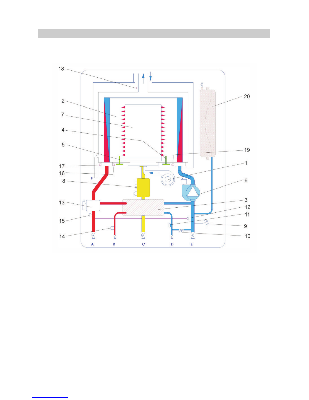
40
Plan 2 - hydraulic diagram
of the Wall Mounted Condensing Gas Boiler with Forced Draught
7. APPENDIX: LISTS AND PLANS FOR MOUNTING AND INSTALLATION
Legend:
1 Modulating fan
2 Primary heat exchanger
3 Secondary heat exchanger
4 Ignition electrode
5 Ionization electrode
6 Circulation pump with automatic
de-aerator
7 Cylindric metal premix burner
8 Gas valve
9 3 bar safety valve
10 Filling tap
11 Flowmeter
12 Automatically bypass
13 Three-way valve
14 DHW temperature probe
15 System water pressure sensor
16 CH flow temperature probe
17 Overheating thermostat
18 Flue gases temperature probe
19 CH return temperature probe
20 Expansion vessel
A CH flow (outgoing water)
B CH return
C Gas supply
D DCW inlet
E DHW outlet
Page 43
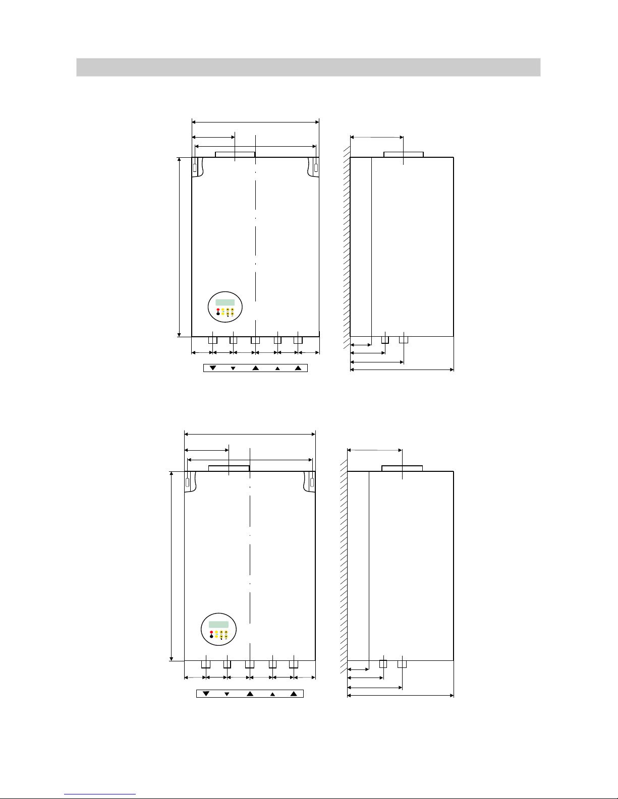
41
Plan 3 - The couplings diagram for MKDENS36 boiler
Plan 4 - The couplings diagram for MKDENS25 boiler
7. APPENDIX: LISTS AND PLANS FOR MOUNTING AND INSTALLATION
6597 786550 65
A B
C
D E
3/4” 3/4” 3/4”
1/2” 1/2”
720
154
340
420
187
30
208
383
GAZ
165
RESET
MOD
6597 786550 65
A B
C
D E
3/4” 3/4” 3/4”
1/2” 1/2”
720
154
340
420
143
30
164
340
GAZ
167
RESET
MOD
Page 44
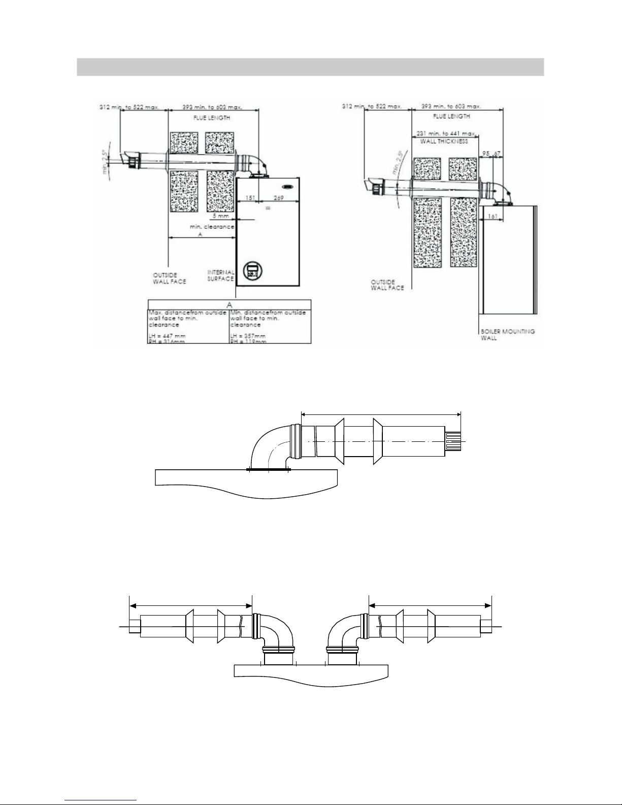
Lmin=1m; Lmax=5m
Lmin=1m; Lmax=5m
Lmin=1m; Lmax=3m
42
CONCENTRIC FLUE SYSTEM
TWIN FLUE SYSTEM
7. APPENDIX: LISTS AND PLANS FOR MOUNTING AND INSTALLATION
Page 45
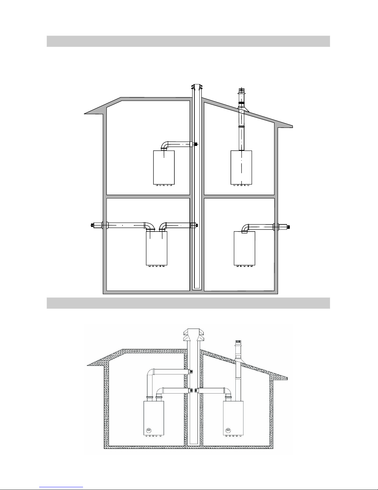
43
Plan 5a, 5b - Typical flue system applications for the
Wall Mounted Condensing Gas Boiler with forced draught
Plan 5a
7. APPENDIX: LISTS AND PLANS FOR MOUNTING AND INSTALLATION
Plan 5b
7. APPENDIX: LISTS AND PLANS FOR MOUNTING AND INSTALLATION
Page 46
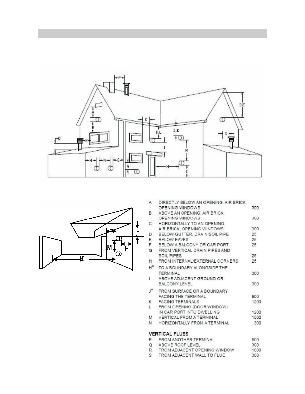
44
Plan 6 - Terminal Clearances for flue installation
UNDER CAR PORT, etc. HORIZONTALFLUES
7. APPENDIX: LISTS AND PLANS FOR MOUNTING AND INSTALLATION
M
H
L
F
J,K
Page 47
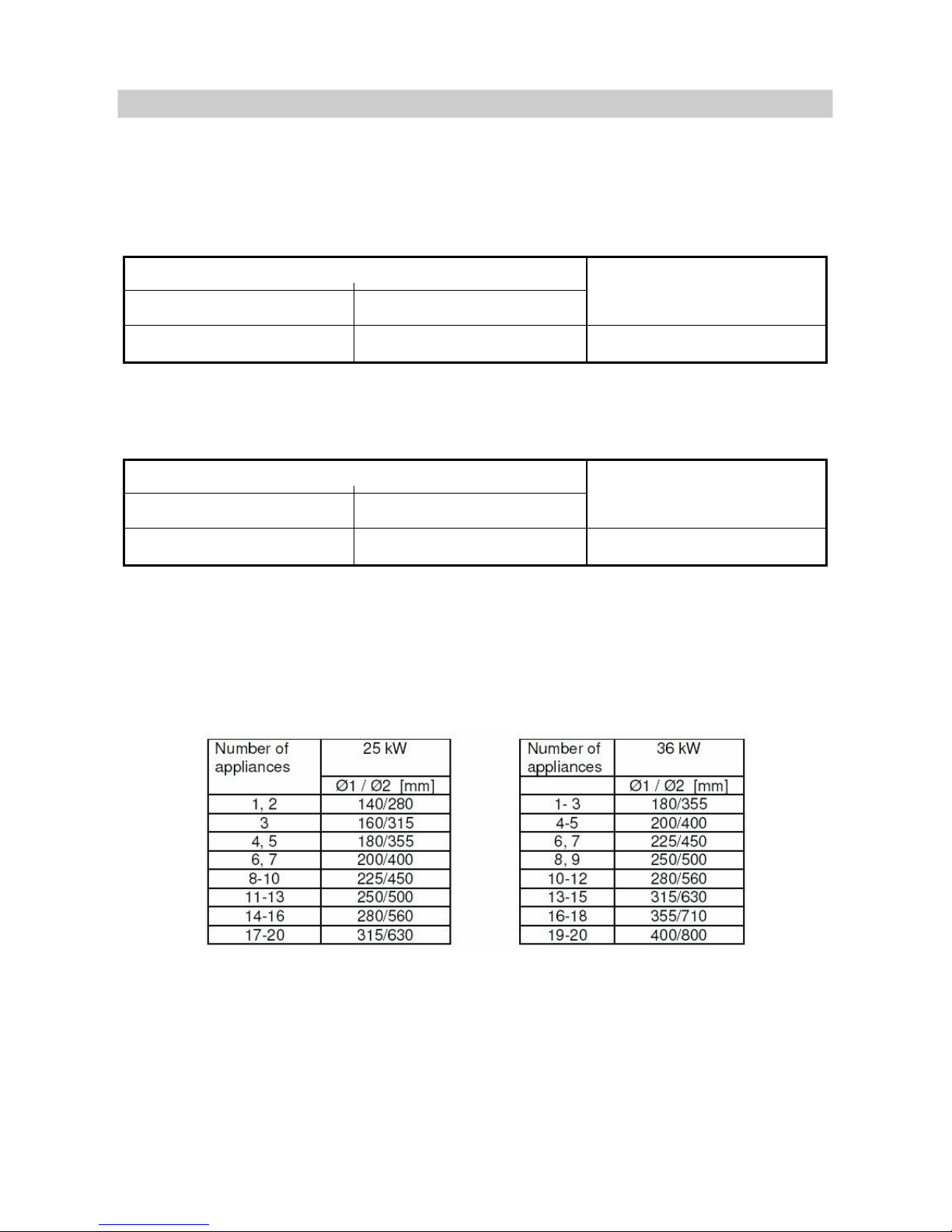
45
Plan 7 - Detalis for C43 and C83 type Flue systems
Details for C Flue System
ATTENTION!
ATTENTION!
43
1. Nominal combustion products temperature = 75 C
2. Overheat combustion products temperature = 90 C
3. Minimum combustion products temperature = 41 C
4. CO2 content = max. 8.9%
5. The MKDENS 36 and MKDENS 25 boilers including connecting
ducts are suitable for connection to a natural draft chimney only.
6. Characteristics of the common duct system:
The total length of air/flue ducts must not increase the overall
pressure lose over 125 pa.
In case of twin common duct flue system the ducts diameters
are those from C83, indicated in the next section.
0
0
0
7. APPENDIX: LISTS AND PLANS FOR MOUNTING AND INSTALLATION
36 kW boiler
25 kW boiler
Combustion fan - FIME
Mass flow rate = 18.4 kg/h Mass flow rate = 16.9 kg/h Mass flow rate = 13.3 kg/h
Combustion fan - EBM
36 kW boiler
25 kW boiler
Combustion fan - FIME
Mass flow rate = 60.3 kg/h Mass flow rate = 57.1 kg/h Mass flow rate = 43.5 kg/h
Combustion fan - EBM
Page 48
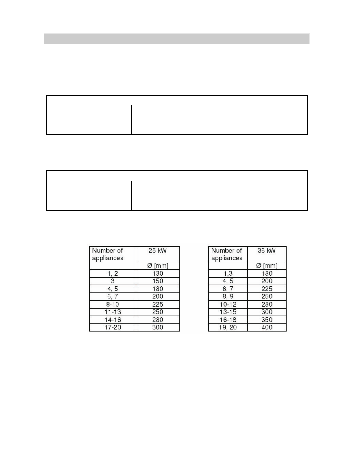
46
Details for C83 Flue System
ATTENTION!
1. Nominal combustion products temperature = 75 C
2. Overheat combustion products temperature = 90 C
3. Minimum combustion products temperature = 41 C
4. CO2 content = max. 8.9%
5. Characteristics of the common duct system:
The total length of air/flue ducts must not increase the overall
pressure lose over 125 pa.
0
0
0
7. APPENDIX: LISTS AND PLANS FOR MOUNTING AND INSTALLATION
36 kW boiler
25 kW boiler
Combustion fan - FIME
Mass flow rate = 18.4 kg/h Mass flow rate = 16.9 kg/h Mass flow rate = 13.3 kg/h
Combustion fan - EBM
36 kW boiler
25 kW boiler
Combustion fan - FIME
Mass flow rate = 60.3 kg/h Mass flow rate = 57.1 kg/h Mass flow rate = 43.5 kg/h
Combustion fan - EBM
Page 49
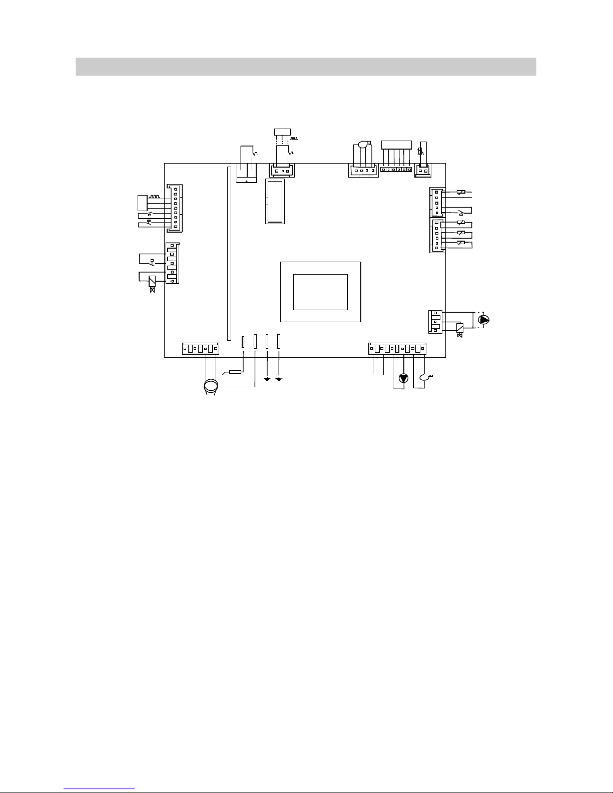
47
Plan 8 - Electrical diagram for the Wall Mounted Condensing Gas Boiler
with forced draught
SYMBOLS:
J14 (HIGH VOLTAGE)
J16 (HIGH VOLTAGE)
J13 (LOW VOLTAGE)
J12 (LOW VOLTAGE)
1: Board power supply (N) -Neutral
2: Board power supply (L) -Phase (230VAC - 50 Hz)
3: Circulator (CI) - Neutral
4: Circulator (CI) - Phase
5: Fan power supply (V) -Neutral
6: Fan power supply (V) -Phase
1: 3-ways valve (VDM) Neutral
DHW circulator (CS) Neutral
2: 3-ways valve (VDM) Normally closed contact NC
3: 3-ways valve (VDM) Normally open contact NA
DHW circulator (CS) Phase
1: Outgoing water CH probe (Sm)
2: Outgoing water CH probe (Sm)
3: Return water probe (Sr)
4: Return water probe (Sr)
5: Combustion products detection probe (Sf)
6: Combustion products detection probe (Sf)
1: Differential water pressure switch (PD)
2: Differential water pressure switch (PD)
3: Not connected
4: DHW probe (Ss)
5: DHW probe (Ss)
7. APPENDIX: LISTS AND PLANS FOR MOUNTING AND INSTALLATION
TRASD
J5
+
-
NA
PA
TS
1
1
TL
VG
J19
N
1
J8
AE
ER
J7
J17
J1
J18
J14
1
N
L
N N
CI
V
1
J16
NA
NC
N
VDM
CS
TA
J6
J9
1
J4
FL/TB/VP
+
-
FLUX
DRIVER
Se
RS 232
J3
J26
J23
J12
1
1
1
+
HS
PWM
GND
1
1
Ss
PD
Sf
Sr
Sm
J13
Page 50

Plan 8 - Electrical diagram for the Wall Mounted Condensing Gas Boiler
with forced draught
J23 (LOW VOLTAGE)
J26 LOW VOLTAGE)
J3 (LOW VOLTAGE)
J4 (LOW VOLTAGE)
J6 (LOW VOLTAGE)
J5 (LOW VOLTAGE)
J19 (HIGH VOLTAGE
J8 (HIGH VOLTAGE)
J9 (LOW VOLTAGE)
J7 (HIGH VOLTAGE)
J17
J1
J18
1: External probe (Se)
2: External probe (Se)
Not used
1: Fan driver GND
2: Fan driver PWM regulation signal
3: Fan driver HS speed signal
4: Fan driver +24 VDC
1: Flowmeter (FLUX) output signal
Flow switch / tank thermostat contact (FL/TB)
2: Flowmeter (FLUX) voltage supply + VCC
3: Flowmeter (FLUX) voltage supply GND
Flow switch / tank thermostat contact (FL/TB)
1: Room thermostat (TA)
2: Room thermostat (TA)
1: Not connected
2: Not connected
3: Water pressure transducer (TRASD) output signal
4: Water pressure transducer (TRASD) voltage supply +VCC
5: Water pressure transducer (TRASD) voltage supply GND
6: Air pressure switch (PA). SHORT CIRCUIT if not fitted
7: Air pressure switch (PA). SHORT CIRCUIT if not fitted
8: Safety thermostat (TS)
9: Safety thermostat (TS)
)
1: Not connected
2: Limit thermostat (TL). SHORT CIRCUIT if not fitted
3: Limit thermostat (TL). SHORT CIRCUIT if not fitted
4: Gas valve (VG) - Neutral
5: Gas valve (VG) - Phase
1: Not connected
2: Not connected
3: Ignition device (AE) Neutral
4: Ignition device (AE) - Phase
FLAT-CABLE 14 poles for the connection of the control board LCD2
Flame detection electrode ER
Ignition device Earth
Board Earth
Board Earth
7. APPENDIX: LISTS AND PLANS FOR MOUNTING AND INSTALLATION
48
 Loading...