

Motan MKDENS 25, MKDENS 36 Technical Instructions

KÖBER LTD DUMBRAVA ROSIE - VADURI BRANCH OFFICE
Branch Office:Vaduri, No. 280, Alexandru cel Bun, Neamt District, Postal Code 617511, Romania
Phone : +40.233.24.17.46, 233.24.19.33, Fax : +40.233.24.19.29
E-mail : , www.motan.rooffice.vaduri@kober.ro
TECHNICAL INSTRUCTIONS
FOR INSTALLATION/ USAGE/ MAINTENANCE
Köber LTD
Vaduri Branch Office
1798
0086
Type: C13SPV36MEF
Type: C14SPV25MEF

KÖBER L.T.D. VADURI BRANCH
implements and certifies the Quality Management System,
according with standard EN ISO 9001:2008.
This certificate assure the conformity of our products.
The quality of our product is the result of permanent
investments in implementing of the highest development and
research technology, profesionalism, experiency and
dedication of employers.
The technical instruction must to be available any time.
The technical instruction is the exclusive property of
KÖBER LTD , VADURI BRANCH
It is forbidden to copy and to distribute the technical instruction
in any other way without the prior written aproval of
KÖBER LTD , VADURI BRANCH
DUMBRAVA ROSIE -
DUMBRAVA ROSIE
DUMBRAVA ROSIE

page
1. DESCRIPTION OF THE APPLIANCE
1.1 GENERAL DESCRIPTION
1.2 BOILER MODELS
1.3 GENERAL INSTRUCTIONS CONCERNING THE BOILER SAFETY
2. BOILER SPECIFICATION
2.1 TECHNICAL DATA
2.2 MAIN COMPONENTS
2.2.1 BURNING SYSTEM (see picture no.1)
2.2.2 HYDRAULIC SYSTEM ( 2)
2.2.3 CONTROL SYSTEM ( )
3. MOUNTING AND INSTALLATION INSTRUCTIONS
3.1 ACCORDANCE WITH THE CURRENT REGULATIONS
3.2 MOUNTING THE BOILER ON THE WALL
3.3 CONECTING THE BOILER
3.4 CONDENSATE DRAINAGE (see figure no.4)
4. PUTTING INTO SERVICE
5. COMMISSIONING
5.1 VERIFY THE POWER SUPPLY TO THE BOILER
5.2 THE FILLING UP
5.3 CONNECT AN ROOM THERMOSTAT AND AN EXTERNAL PROBE
5.4 VERIFY THE GAS TYPE
5.5 THE MEASUREMENT OF STATIC PRESSURE
5.6 THE MEASUREMENT OF DYNAMIC PRESSURE
5.7 VERIFY THE EXHAUST SYSTEM
5.8 INITIAL LIGHTING
5.9 INSTRUCT THE USER
6. USAGE INSTRUCTIONS FOR THE END USER
6.1 CONTROL PANEL
6.1.1 BOILER CONTROL UNIT - POWER ON
6.1.2 “CENTRAL HEATING” MODE (symbol 8 ON)
6.1.3 “DOMESTIC HOT WATER - DHW” (symbol 7 ON)
6.1.4 SYSTEM WATER PRESSURE CHECKING
6.1.5 ADDITIONAL FACILITIES
6.1.6 THE BOILER SHUTTING-DOWN IN SAFETY CONDITIONS
see picture no.
see picture no.4
6.2 FUNCTIONS CONCERNING BOILER SAFETY
6.3 ERRORS DETECTION
6.4 DELIVERY THE BOILER TO THE END USER AFTER INSTALLATION
TABLE OF CONTENTS:
3
4
5
6
7
7
8
8
9
11
12
12
13
13
19
20
21
22
22
23
25
25
25
25
26
26
27
27
30
31
31
31
31
32
32
33
34

6.5. ROUTINE SERVICING
6.6. STORAGE, MARKING, DOCUMENTS, PACKING, TRANSPORT
6.7 QUALITY AND GURANTEE CONDITIONS
6.8 RESPONSIBILITIES DURING THE WARRANTY PERIOD
7. APPENDIX: LISTS AND PLANS FOR MOUNTING AND INSTALLATION
Plan 1 - The couplings arrangement
2 - Hydraulic diagram
3 - The couplings diagram for MKDens36
5a, 5b - Typical flue system applications
6 - Terminal clearances for flue installation
7 - Lists and plans for mounting and installation
8 - Electrical diagram
Plan
Plan
Plan 4 - The couplings diagram for MKDens25
Plan
Plan
Plan
Plan
34
35
36
37
39
39
40
41
41
43
44
45
47
TABLE OF CONTENTS:

PLEASE RESPECT STRINGENTLY THE INFORMATIONS OF
TECHNICAL INSTRUCTION. OTHERWISE, CAN APPEAR FIRE AND BLOW
UP RISK WHICH CAN LEAD AT MATERIAL PREJUDICE, PERSON'S INJURY
OR EVEN DYING.
VERYIMPORTANT!
IT IS THE LAW THAT ALL GAS APPLIANCES ARE INSTALLED BY A
COMPETEND PERSON. IT IS IN YOUR OWN INTEREST AND THAT OF
SAFETY TO ENSURE THAT THE LAW IS COMPLIED WITH.
DO NOT STORE OR USE FLAMMABLE MATERIALS IN THE VICINITY
OF GAS BOILER.
DO NOT USE THE GAS BOILER IF ANY OF HIS COMPONENTS HAVE
BEEN FLOODED.
INFORM URGENTLY THE SERVICE PEOPLE TO INSPECT THE GAS BOILER
AND TO REPLACE THE FLOODED COMPONENTS.
IN CASE YOU FEEL GAS FLAVOUR, RESPECT THE FOLLOWING
OPERATIONS:
- DON'T SWITCH ANY LIGHT OR FLAME
- DON'T TOUCH ANY LIGHTING SWITCH
- CALL URGENTLY THE GAS SUPPLIER. DON'T USE THE PHONE IN
THE BUILDING WHERE IS INSTALLEDTHE GAS BOILER
- IF YOU CAN'T CONNECT WITH THE GAS SUPPLIER, CALL THE
FIRE BRIGADE.
INSTALLING, COMMISSIONING, ROUTINE SERVICE WILL BE MADE
ONLY BY QUALIFIED SERVICE ENGINEERS, QUALIFIED SERVICE
CORPORATIONS OR BY GAS SUPPLIERS.
THIS APPLIANCE IS NOT INTENDED FOR USE BY PERSONS
(INCLUDING CHILDREN) WITH REDUCED PHYSICAL OR SENSORY
CAPABILITIES, OR LACK OF EXPERIENCE AND KNOWLEDGE, UNLESS
THEY HAVE BEEN GIVEN SUPERVISION BY A PERSON RESPONSABILE
FOR THEIR SAFETY.
1. DESCRIPTION OF THE APPLIANCE
SATEFY MEASURES
3

The Motan MKDENS wall mounted gas boiler is a fuel gas consuming
appliance, that has the role of turning the fuel gas power into thermal energy
through burning. This appliance operates unsupervised due to its protection and
control systems.
The boiler consists of many components that are described in the following
chapters.
The gas enters inside the boiler through the gas supply circuit made of a
coupling and a reducing valve, which must be set at 20 mbar for G20 H subgroup.
After the reducing valve, the gas enters the gas valve and, further, the Venturi tube.
The boiler is equipped with an air fan, which ensures the forced draught.
The rotation speed of the fan is variable (control is made by modulation).
In the pre-purge phase, the fan evacuates an air volume to provide a safe ignition.
Otherwise, an explosive ignition might occur due to gas storage from non-operating
periods.
The air delivered by the fan enters the Venturi tube, where it draws in (by
suction) and entrains the fuel gas suppliedby the gas valve. The air and fuel gas are
mixed in the Venturi tube diffuser.The resulted air gas mixture supplies the burner.
The assembly fan gas valve Venturi tube ensures a constant and
optimum air gas ratio at any load of the boiler.
The flame ignition is performed by an ignition electrode, by means of an
ignition transformer. During the combustion, the flame sensing is ensured by an
ionization sensor.
The main heat exchanger is made of stainless steel and has an annular
shape. Inside this cylinder, the combustion chamber is placed. The main heat
exchanger is designed to allow the heat transfer from the combustion gas to the
water with minimal heat leakages.
In case of the Central Heating (CH) circuit, the heat resulted from fuel gas
burning is taken over by the main heat exchanger and sent to the water which is
delivered by the circulating pump through the heating installation.
When the flowmeter detects flow in the Domestic Hot Water (DHW) circuit,
the three-way valve switches from the central heating circuit to the short circuit that
includes the plate heat exchanger; in this case, the heat resulted from fuel gas
burning is transferred to the domestic water.
The system monitoring and control are electronically performed. The boiler
setting is made from the control board (see the chapter concerning this subject).
1.1 GENERAL DESCRIPTION
4

5
C13, C14 - model code
S - with instant delivery of hot water (without external water tank)
P - with circulation pump
V - with sealed expansion vessel
36, 25 - maximum gross output in kW
M - continuous modulating air - gas supply system
E - electronic control and supervision of ignition and flame
F - forced draught
1.2 BOILER MODELS
MODEL NUMBER CODING
TYPE
C13SPV36MEF
C1 SPV MEF4 25
Maximum Output
Accesories
[kcal/h] KW
36
25
Fan Pump
Expansion
vessel
DHW instant
production
30954
21496
X
X
X
X
X
X
X
X
Type: C13SPV36MEF
Type: C14SPV25MEF

6
! This manual is part of the product and must be given to the user.
The commissioning and service operations is made only by authorized service
engineers.
Read this manual carefully and keep it carefully for a further application by the
user and by the mounting and installing authorized personnel.
The installation must be to the current Gas Safety (Installation and Use)
Regulations and must be installed by a competent person. The installation, the
putting into service, the service repair operations and the periodical technical
checking are performed only by authorized personnel in accordance with the
current standards and installation code.
All the indications from this manual must be respected; any exception may
cause damages and the manufacturer is not responsible for them.
In case of a defective running of the device, shut it down and call up
immediately one of the authorized breakdown services units .
To guarantee the boiler efficiency and its correct operation it is recommended
that the boiler be checked periodically by qualified personnel, complying with the
manufacturer conditions.
If the device is sold or given, make sure it is delivered with its technical
handbook in order to be consulted by the new user/ installer.
In case of some components damaging there will be used only the original
components. You must have the manufacturer's permission to use some
components from another company. You must obtain the written acceptance of
the producer so that you may use those components.
This boiler will be used properly.Any other use will be considered unsuitable.
There is excluded any contractual or extra-contractual responsibility of the
producer for the damages caused by the installing or usage errors and by the nonobservance of his instructions.
It is compulsory to install a softener filter on the domestic water circuit, a
mechanical impurities filter (Y filter) on the CH installation return and a pressure
controller on the gas supply circuit.
Not submitting to these technical manual regulations and to those from the
warranty certificate leads to warranty loss.
!
!
!
!
!
!
!
!
!
!
!
!
1.3 GENERAL INSTRUCTIONS CONCERNING THE BOILER SAFETY
7
Commercial Name MKDens 25 MKDens 36
Type
C14SPV25MEF C13SPV36MEF
Gas category
Draught type
Combustion chamber
Energy Efficiency Band (natural gas)
Nox class (natural gas)
Net efficiency at rated output (natural gas)
Net efficiency at 30% part-load (natural gas)
Maximum CH gross Heat input, Q
Maximum CH heat output, P (at 100% load)
Weight
Capacity of the heat exchanger
Maximum gas rate (natural gas)
Heating circuit - Flow rate
Heating circuit - Min. and max admitted pressure
Heating circuit - Outgoing water temperature
Connections - inlet-outlet CH
Connections - inlet-outlet DHW
Connections - gas supply
Minimum CH heat output, P
Maximum DHW output, P (at 100% load)
Natural gas pressure on coupling (behind the reducer)
Maximum inlet pressure
Power supply
Power consumption
Minimum CH gross Heat input, Q
Maximum CH net Heat input, Q
Minimum CH net Heat input, Q
I2H (20)
Forced
Closed
5
96.7%
106.7%
26.6 kW
5.2 kW
24.0 kW
4.7 kW
26.6 kW
24.0 kW
24.3 kW
42 kg
1.75 l
2.65 Nmc/h
0.8 mc/h 0.8 mc/h
0.8 si 3 bar
30 - 80°C 30 - 80°C
3/4”
1/2”
3/4”
4.9 kW
24.5 kW
20 mbar
25 mbar
230V / 50 Hz
175 W
230V / 50 Hz
175 W
I2H (20)
Forced
Closed
5
96.7%
106.5%
36.3 kW
8.1 kW
31.8 kW
7.3 kW
36.4 kW
32.8 kW
32.3 kW
48 kg
2.45 l
3.58 Nmc/h
0.8 si 3 bar
3/4”
1/2”
3/4”
7.6 kW
33.3 kW
20 mbar
25 mbar
Maximum DHW gross Heat input, Q
Maximum DHW net Heat input, Q
2.1 TECHNICAL DATA
2 BOILER SPECIFICATIONS
A A
8
It is designed to supply the necessary heat for CH and DHW circuits.
It consists of the following elements:
. It must include a reducing valve that will set the inlet pressure at
20-25 mbar NG. It is compulsory to mount a pressure controller on the gas supply circuit.
. The boiler is equipped with an air fan (forced draught).
The rotation speed of the fan is variable; its control is made by modulation.
. It is designed to ensure the gas supply at any load
from the minimum load to the maximum load.
It ensures the mixing of air and fuel gas: the air delivered by fan draws
in (by suction) and entrains the fuel gas delivered by the gas valve; the air and fuel gas
are mixed in the Venturitube diffuser. The resulted air gas mixture supplies the burner.
The assembly fan gas valve Venturi tube ensures a constant and optimum air gas
ratio at any load of the boiler.
. It is a PREMIX type, made of stainless steel and has a cylindrical shape. It
operates on positive relative pressure. The burner output is controlled by means of a
modulating fan.
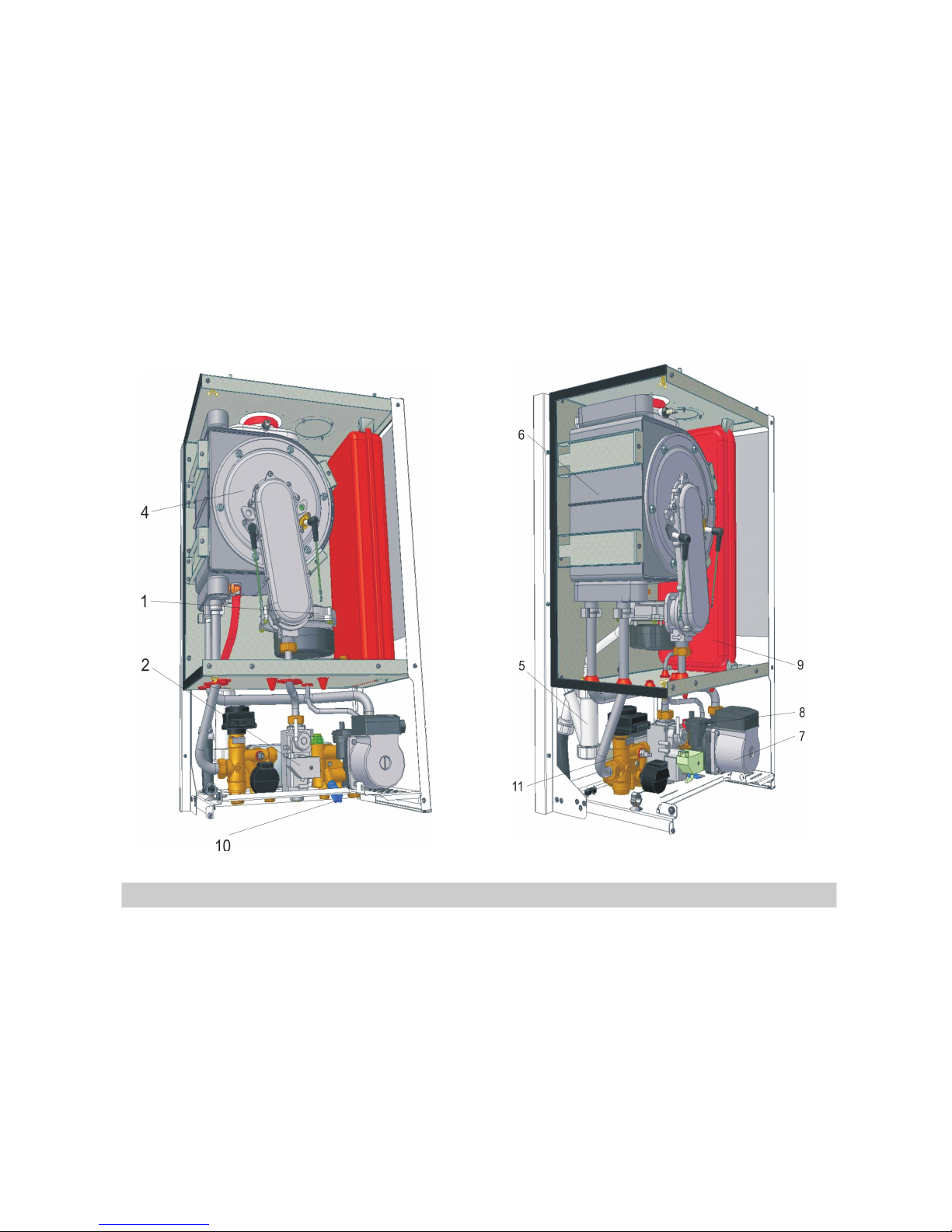
1. Gas supply circuit
2. Fan (position 1 picture 1)
3. Gas valve (position 2 picture 1)
4. Venturi tube.
5. Burner
Dimensions (mm) Depth
720 720
Width
Height
With mounted elbow
420 420
340 383
850 850
Expansion vessel
Domestic Hot Water Temperature
DHW flow rate
t = 35°C
t = 40°C
t = 25°C
Domestic cold water pressure
Flue gases temperature
Draught
Concentric flue kit - diameters
Twin flue kit - diameters
7 l
0.2 - 8bar
62 °C 62 °C
0.2 - 8bar
0.015 hPa 0.015 hPa
D100 / D60 D100 / D60
D80 / D80 D80 / D80
3m (maximum)
4m (maximum)
3m (maximum)
4m (maximum)
150 l
8 l
200 l
Length of the concentric flue duct
Lenght of the twin flue duct
Guiding values
Maximum water content in the installation
30 - 60°C
14.3 l/min
10.2 l/min
8 l/min
20.6 l/min
14.7 l/min
11.5 l/min
30 - 60°C
2.2.1 BURNING SYSTEM (see picture no.1)
2.2 MAIN COMPONENTS
6. Combustion chamber (position 4 picture1).
7. Air and flue gases ducts.
8. Condensate trap (position 5 picture1)
Picture no.1 Picture no.2
1. Main heat exchanger (position 6 picture 2)
It is sealed and has a cylindrical
shape. It is placed inside the main heat exchanger (annular shaped). To reduce
the heat leakages, both front and rear walls of the combustion chamber are
isolated indoor with heat insulating material (ceramics fibers). On the front wall is
placed the burner.
According to the situation, can be concentric or
eccentric type. In both cases, the air duct is connected to outside environment.
The flue gases duct can be connected to the outside environment or to a chimney.
. It is specific to the condensing boilers
and must be always filled with water (condensate). Otherwise, there is a danger
that fumes might escape in to the room and cause poisoning.
It consists of the primary circuit and the secondary circuit (DHW circuit).
The primary circuit takes over the heat resulted from fuel gas burning and sends it
to the heating installation or to the secondary circuit.
The main components of the hydraulic system are:
. Takes over the heat resulted
from fuel gas burning and sends it to the water from the primary circuit. Is made of
stainless steel and has an annular shape. Inside this cylinder, the combustion
chamber is placed.
2.2.2 HYDRAULIC SYSTEM (see picture no.2)
9
10
2. Circulating pump (position 7 picture 2)
3.Automatic air vent (position 8 picture 2)
4. Expansion vessel (position 9 picture 2)
5. Safety valve
4.Automatic by-pass
5. Filling system
6. Three-way valve (position 11 picture 2)
7. Plate heat exchanger
.
It is designed to supply the necessary water flow in the primary circuit in
both modes Central Heating and Domestic Hot Water.
Also, it must be aware of the hydraulic features of the pump, presented in
the figure 1:
.
It ensures the air discharge from the primary circuit. It is mounted on the circulating
pump shell.
.
It allows the expansion of the hot water from the primary circuit. Thus, the hydraulic
overstraining and/or damaging are avoided.
.
It limits the maximum water pressure in the primary circuit to 3 bar. If the water
pressure increases over 3 bar, the safely valve opens automatically and primary
circuit is drained. The safety valve closes when pressure drops under 3 bar.
.
It allows the heat carrier recycling through the heat exchanger and pump, in case of
pressure differences (between the external heat installation turn and return) at
over 0.3 bar.
.
It allows filling of the heating installation with water. It must be used when the
system water pressure is too low. If the system water pressure decreases
accidentally, the heating installation must be carefully checked before the filling
procedure.
.
It allows routing of the thermal agent from the primary circuit towards the heating
installation or the plate heat exchanger - according to the operating mode (CH or
DHW). It is electrically controlled.
.
It takes over the heat carried by the water from the primary circuit and sends it to
the domestic water from the secondary circuit. In this way, the domestic hot water
is prepared.
Pumping height
Pump water flow
0
0
1
1
2
20
2
3
3
4
40
5
6
H
[m]
H Hp
kPa[ ]
0.0 0.2 0.4 0.6 0.8 1.0 1.2 1.4 1.6 1.8 2.0 2.2 2.4 2.6 2.8
Q m /h[ ³ ]

11
Is made by the following elements:
It monitors and controls the operation of
the boiler.
Send temperature signals (CH flow and
return) to the electronic board. In this
way, instantaneous values of the
temperatures can be displayed on LCD
and the gas rate can be adjusted in
order to deliver water at the set
temperature. In addition, when CH flow
a n d r e t u r n p r o b e s i n d i c a t e
temperatures over admitted limits,
malfunctions can be signaled.
1. Boiler control unit (position 12
picture 4)
2. CH flow and return temperature
probes (position 13 picture 4)
Picture no.3
3. DHW temperature probe (position 14 picture 4)
4. Overheating thermostat(position 15 picture 4)
5. Waterpressure sensor (position 16 picture 4)
6. Flowmeter (position 17 picture 4)
7. Fan speed sensor
8. Ignition electrode (position 18 picture 4)
9. Ionization electrode (position 19 picture 4)
It sends information about the temperature in the DHW circuit to the electronic
board. Thus, the instantaneous value of the DHW temperature can be displayed
and the gas rate is adjusted according to this information in order to deliver
domestic hot water at the set temperature.
It cuts off the fuel gas supply when the maximum allowed temperature of the
outgoing water is exceeded. In this situation, the boiler goes in lockout state; in
order to exit the lockout state, the RESETkey must be pressed. The thermostat is
placed on the outgoing water pipe, close to the main heat exchanger.
It sends information about the water pressure from the heating system to the
electronic board. In this way, the instantaneous value of the pressure can be
displayed and the user can be notified in case of low water pressure.
It detects and measures the water flow in the DHW circuit.
It sends information about the fan rotation speed to the electronic board. This
information allows optimization of the burning process at any load.
It ensures the spark generation in the ignition stage.
It provides information about the flame status, ensuring a safe combustion. When
the flame is missing, the fuel gas supply is cut off and the boiler goes in the lockout
state.
2.2.3 CONTROL SYSTEM (see picture no.4)

10. Flue gases temperature probe (position 20 picture 4)
11. External probe (optional)
12. Chrono-thermostat or room thermostat (optional)
The control system achieves the following:
It cuts off the fuel gas supply when flue gases temperature exceeds 90°C. It is
placed in the flue gases collector, which is located above the main heat exchanger.
It ensures an optimum temperature of the water from the heating installation,
when the external temperature is in the range -20...20°C.
It keeps the room temperature at the user set value. It is provided on demand
(optional).
Ignition control and flame drop out protection;
Gas rate adjustment according to the user requirements regarding water
temperature;
Temperatures signaling for both CH and DHW circuits;
System water pressure signaling;
Protection against fuel gas cut offs;
Protection against overheating of the heating circuit;
Protection against excessive water pressure;
Protection against water loss in the primary circuit;
Protection against clogging of the condensate drain system.
!
!
!
!
!
!
!
!
!
12
The EC type examination certificates eliberated for this types of combi
boilers, by official and autorized bodies, shows the accordance of the appliance
with the current regulations and gives the presumption of the conformity with the
GasAppliances Directive, Low Voltage Directive and Electromagnetical Directive.
This chapter addresses both to the qualified personnel that
performs the boiler installation and to the beneficiary that is concerned that
the mounting and installation of the boiler are performed following the
safety rules in operation of all the installations which contribute to the good
running of the boiler.
THE BOILER INSTALLATION IS NOT THE SAME WITH THE BOILER
STARTING.
THE BOILER STARTING MUST BE DONE BY QUALIFIED
PERSONNEL AND AUTHORIZED IN ACCORDANCE WITH THE CURRENT
LEGISLATION.
THERE IS NO GUARANTEE WITHOUT THE AUTHORIZED
PERSONNEL SIGNING THE PUTTING INTO SERVICE STATEMENT, AND
THE COMPANY WITHDRAWS ANY BOILER GUARANTEE OR RUNNING
RESPONSIBILITIES.
3. MOUNTING AND INSTALLATION INSTRUCTIONS
3.1 ACCORDANCE WITH THE CURRENT REGULATIONS

The boiler is designed to be use in integrated in heating systems in closed
chambers. It is forbidden to mount the boiler outside the building.
The appliance has the protection level IP 40;
Improper climate conditions of installing the boiler
automaticcaly conduct to warranty lose.
It shall be performed only if all the conditions concerning the connection
of the boiler are respected (see the chapter 3.3 “Connecting the boiler”).
· - Remove the packing.
· - Make two holes on the wall, at a desired height, by using the pattern
drawn on the boiler pack.
· - Fix the two dowels on the wall and then mount the two hooks by
screwing up. The dowels and hooks are provided with the boiler.
· - Fix the boiler on the wall by inserting the hooks into the two holes made
on the posterior side of the boiler.
- Check the stiffness of the boiler fixed on the wall, to be sure that the
structure of boiler is not stressed
ATTENTION!
13
3.2 MOUNTING THE BOILER ON THE WALL
The boiler must be connected to a mono-phase network of 230V / 50Hz
with ground protection, through a 5A fusible plug. The color semantics will be as
follows: brown= phase, blue=null, green/yellow=earth.
Insert the plug into connection, so that the phase of the network to correspond to
the brown wire of the supply cable.
The correct polarity of the supply connection can be identified by using a
multimeter..
Connecting the boiler to the electric power supply, water, gas,
heating installations and air / flue gases ducts can be performed only by
authorized personnel for mounting / installingactivities.
THE CONNECTION TO THE ELECTRIC NETWORK MUST BE
ACCOMPLISHED ACCORDING TO THE CURRENT LEGISLATION AND
STANDARDS.
IT IS FORBIDDEN TO INSTALL THE BOILER WITHOUT EARTH
CONNECTION .
ONLY THE MANUFACTURER OR THE AUTHORIZED PERSONNEL
CAN REPLACE THE ELECTRICAL POWER SUPPLY CABLE IF DAMAGED.
Electric power supply
ELECTRICAL PROCEDURES
3.3 CONNECTING THE BOILER
 Loading...