

MOTALA HISSAR AB
mc200501
Luxorgatan 1
Box 4029
591 04 Motala
SWEDEN
Tel: +46 (0)141-23 70 50
LOW SPEED LIFT
MC2000
2-6 landings
Automatic/manual doors
Assembly Instruction Manual
Release 2.02 2011-10-20


Safety regulations 3
Wordlist 4
ols 5
To
Preparations before assembly 6
Use the layout drawing for erection site check 6
Lift material 6
Lift well construction planning 6
Assembly 7
Introduction 7
General information on how to erect modules 7
Construction of precision gauge blocks 7
Lift well assembly according to layout drawing. 9
Installation of electric cables and wires 23
Guide rails 24
Driving shafts, gear and motor 27
Connecting pit functions 29
Connecting control panel wiring 30
Connecting drive command box 30
Door panel and removal of work platform 31
Commencing with drive command box 32
Chain jointing rod 32
Platform 33
Fixing lift well 35
Sills 35
Fixing plates 36
Travelling flex cable, panel plate, overload unit and control panel 37
Cancelling drive command box 41
Ceiling 41
Commencing from platform control panel 42
43
Lock arms 43
Highspeed contact and magnet 43
Lubrication 44
Cover plates 45
Finishing work 47
Final inspection and own inspection 47
Layout drawing 48
Checklist 49
Approvals and version history 50
Attachments
MOTALA HISSAR AB
Luxorgatan 1
Box 4029
59104 Motala
SWEDEN
Tel: +46 (0)141-23 70 50


MC2000 – Assembly Instruction Manual
mc200501
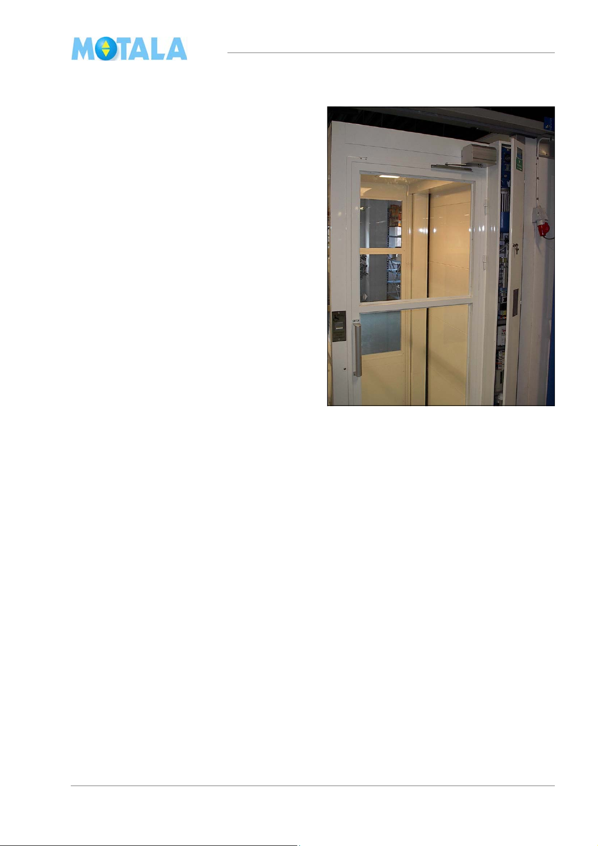
Introduction
This assembly instruction manual shows you
how to erect Motala Hissar MC2000 with 2-6
landings and manual or automatic doors.
The texts
and the illustrations of the manual
show an MC2000 with 2 landings, but are also
valid for lifts with several landings. Note that the
manual also describes the assembly of equipment that is not found in all lifts.
MC2000 can be delivered with straight or
adja-cent two-way entrances. For power
supply, see the current electrical diagram.
The assembly instructions are based on
equip-ment and tools that were accessible
when the manual was written. Because of
continuous product development we reserve
the right to al-terations without further notice.
Safety regulations
Important!
For your own safety and for the safety of others,
follow the existing safety regulations.
Warning! Risc to get jammed! Do not work in
the pit without necissary pre-actions, use the pit
prop, use the stop button, switch off the power!
3

MC2000 – Assembly Instruction Manual
Wordlist
Adjacent lift Lift with door or doors on sides B or D.
Chain joint For connecting the chain between the guide rail sections and
tween the chain and the jointing rod.
be
Clamp coupling For jointing the driving shaft.
Corner profile 100x40 Non-drive side corner.
Corner profile 250x40 Drive side corner.
Door front (With door frame, lock etc).
Drive command box For temporary driving.
Drive command panel Plate with control buttons, attached to the panel shelf and
he panel plate.
t
Drive side The side where the guide rails are placed. This is the wider
ide if you look at the door frame. Can be on the B or D side
s
FF Finished floor.
Glass module Glass module on the long and short sides.
Jointing rod 12x12 mm square rod for adjusting the chain tension.
Jointing sleeve U-section to be put between two corner profiles.
Lift well module Isolamine. Product and expression for 25 to 35 mm thick iso-
lated steel modules.
Non-drive side E.g. side B if the guide rails are on side D.
Panel plate The plate to which the panel shelf and the control panel are
ached.
att
Panel shelf Steel shelf with electric equipment, attached to the panel
ate.
pl
Passage contact Contact which straps across the lock contact when the lift is
the landing zone.
in
Platform Floor frame, floor plate
Pit prop (in the pit) Yellow safety bar that can be raised.
Safety gear test equipment. Attached below the gripping lever. Remote-released by a
ord in the control panel.
c
Side A The side where the motor and gear are placed.
Side B The side placed clockwise next to side A.
Side C The side opposite side A.
Side D The side placed clockwise next to side C.
Slide Flat bar iron with sliding guide shoes where the chain is fas-
tened.
Turning case Cut plastic case where the chain changes direction.
Two-entrance lift. Lift with doors on side A and side C.
Two-metre fixing plate angles. Fixings for the large cover plate above the guide rails.
Work platforms Occasional platforms for building lift wells.
4

MC2000 – Assembly Instruction Manual
Tools
Tools/Equipment with item numbers can be ordered from Motala Hissar AB.
Equipment
Sets of dimension sticks, 1480 mm, 1081
m, 1181 mm.
m
Work platforms, standard set. 705658 For lift well construction. For about three
Drive command box complete with 25 m
ble.
ca
Winch or telpher, min. approx 100 kg. 705867 For lifting guide rails.
Lifting eye bolt with lock, see ill 6 on
page 25.
Fastening rod (telescopic) 705824 For suspending the winch in the well top.
Chain fixing tool. 701268 To prevent the chain from sliding during as-
Glue sprayer. 101428
Structural glue. 100510 Gluing of platform floors.
Grease and lubricating substances. Lubrication of guide rails and lock arms.
Lifting tool (suction cups), 2 pieces 101423 For glass and lift well modules.
Working place illumination
Spirit-level, short, approx, 500 mm
MH item
numbe
705827 For lift well construction, outside dimensions:
705868 For driving the lift during assembly and test-
705826 For lifting guide rails.
r
Notes
depth 1560mm x width 1150 mm/1250mm.
rs. Extra equipment to be ordered
floo
ing.
sembly.
Spirit-level, long, approx, 2000 mm
Measure tape/folding rule, plumb.
Measuring instruments
Tools for electric installation
Jigg saw with long blade “120mm”. For cutting lift well modules “35mm thick”.
Wire shears For cutting wires and wire covers.
Electric screw driver with extender and bits,
pe ph2.
ty
Ratchet with extender and sleeves 13 mm
nd 17 mm.
a
Ring-open-end spanners 7-17 mm.
Plate shears
Riveting tongs
Drill, diameter 3.3, 4.2, 6 and 12 mm For pop rivets and making holes in jointing
ods for drive chains.
r
Hand tools: multi-purpose pliers, screwdrivers, socket wrenches etc.
Hack saw For sawing the joint rod of the drive chain.
Crowbar
5
MC2000 – Assembly Instruction Manual
2
A
D
B
Preparations before assembly
Use the layout drawing for erection site check
Measurments
There is an example under the heading “Layout
awing” on page 48. (The measurments in the
dr
picture are taken from that example.)
Check that the pit:
• has the correct measurments
• is even and level
• is painted.
C
1590
Check the lifting heights (FF-FF). Check that
the floors are completed, i.e. have the correct
height.
Use the plumblines to measure the openings of
e joists. Also check that the diagonal meas-
th
ures of the openings are equal.
Check that the erection space is at least 30 mm
the maximum height of the lift.
above
Check the wall opening dimensions in front of
e door sections according to the layout draw-
th
ing.
Free space for doors
Check the space available for opening doors,
king the inclination of the floors into consider-
ta
ation. Are the doors hung correctly - right or
ft?
le
Free space for the pit prop
Check the space available for the pit prop. See
e layout drawing.
th
Power supply
Check that there is power supply for the lift, the
llumination and the telephone. Compare with
i
the electrical diagram and the layout drawing.
Other facts
Go through and make sure what parts of the lift
e to be powder coated or just primed consid-
ar
ering the framing of joists, walls etc. at the erection site. See the object description enclosed
h the delivery of the lift. Also check the plac-
wit
ing of glass modules, if any.
60
1280
mc20050
Lift material
Check at arrival
Check the number of packages against the
gnment note and the equipment against
consi
the packing list.
Check that nothing is damaged or missing.
Placing
Transport the material to the erection site and
ace it on the appropriate floor. Use the
pl
“checklist”. See example under the heading on
page 49. The door frames are marked on the
bottom side of the profile with an 0, I, II, III or IIII,
dependi
ng for which floor they are intended.
Lift well construction planning
• Where do glass module sections start and
end, if any? The first lift well module might
have to be adjusted so that the glass modules are at the right height above the correct
sts higher up in the lift well. See the lay-
joi
out drawing.
• Where are the channels for lock wires and
es? (These channels can be found in
cabl
adjacent lifts and in two-entrance lifts.)
6
MC2000 – Assembly Instruction Manual
100
100
100
100
mc200553
mc200552
8
Assembly
Introduction
This section contains general information on
o construct so called precision gauge
how t
blocks and how to erect lift well modules and
glass modules.
General information on how to erect modules
Lift well modules
Generally, each module is assembled with four
ews in the corner profiles. The screws are
scr
placed about 100 mm from the upper and lower
edges.
For a nicer look, the screws can be exchanged
pop rivets (4 mm).
by
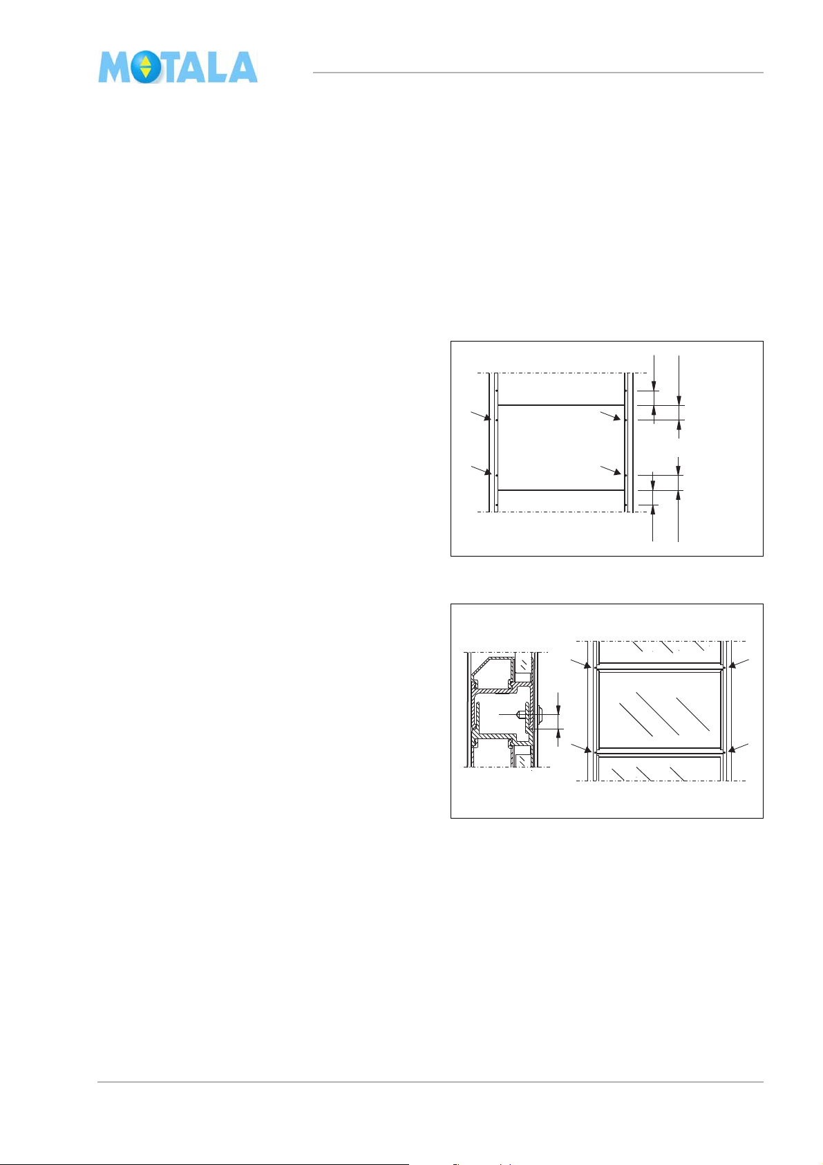
Glass modules
Glass modules are to be placed with the bevelled window moulding on the outside of the lift
. (The flush side on the inside.)
well
The modules are generally put together so that
each modul
e is fastened with four screws in the
corner profiles. You need to pre-drill 3,2mm.
The screws in the splice between two modules
placed about 8 mm from the lower edge of
are
the upper module so that the screw also goes
through the male profile of the lower module.
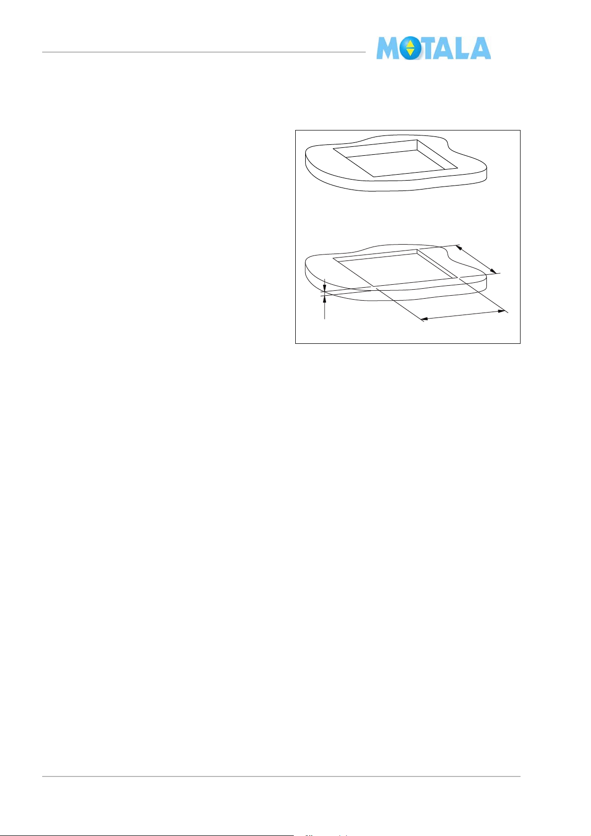
Construction of precision gauge blocks
For glass modules, precision gauge blocks are
used at joist passages and in the pit so that the
glass surfaces are placed at the proper height
according to the layout drawing. Note that the
measurements in the layout drawing apply to
cutting measurements of the precision gauge
blocks. Example: see the heading “Layout
drawing” on page 48
7
MC2000 – Assembly Instruction Manual
1
2
2
1
1
4
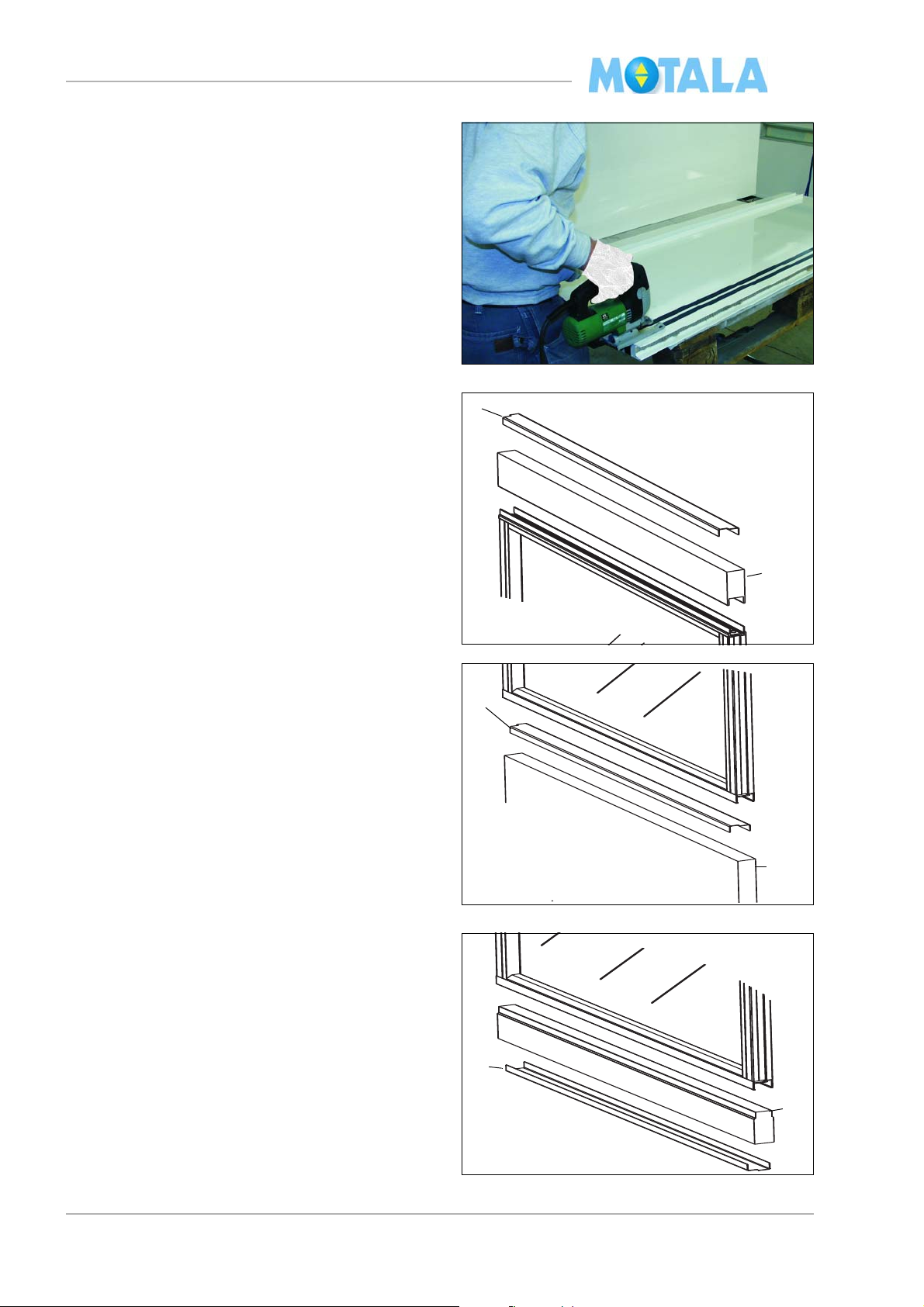
1. Cut the lift well modules with a jigg saw.
Protect the surface with insulating tape or
something similar.
2. Remove the sharp edges.
3. Turn the U-profile with notch 1 towards the
side of the lift well. Note that the top U-
out
profile looks different.
Finish (top clearance of lift well)
Use female section 2 of a lift well module.
Joist passage
Use female section 2 of a lift well module.
Pit
For glass modules, for example.
Use male section 4 of a lift well module.
8
MC2000 – Assembly Instruction Manual
mc200505
2
1
3
4
C
A
D
B
100
100
mc200506
8
5
7
6
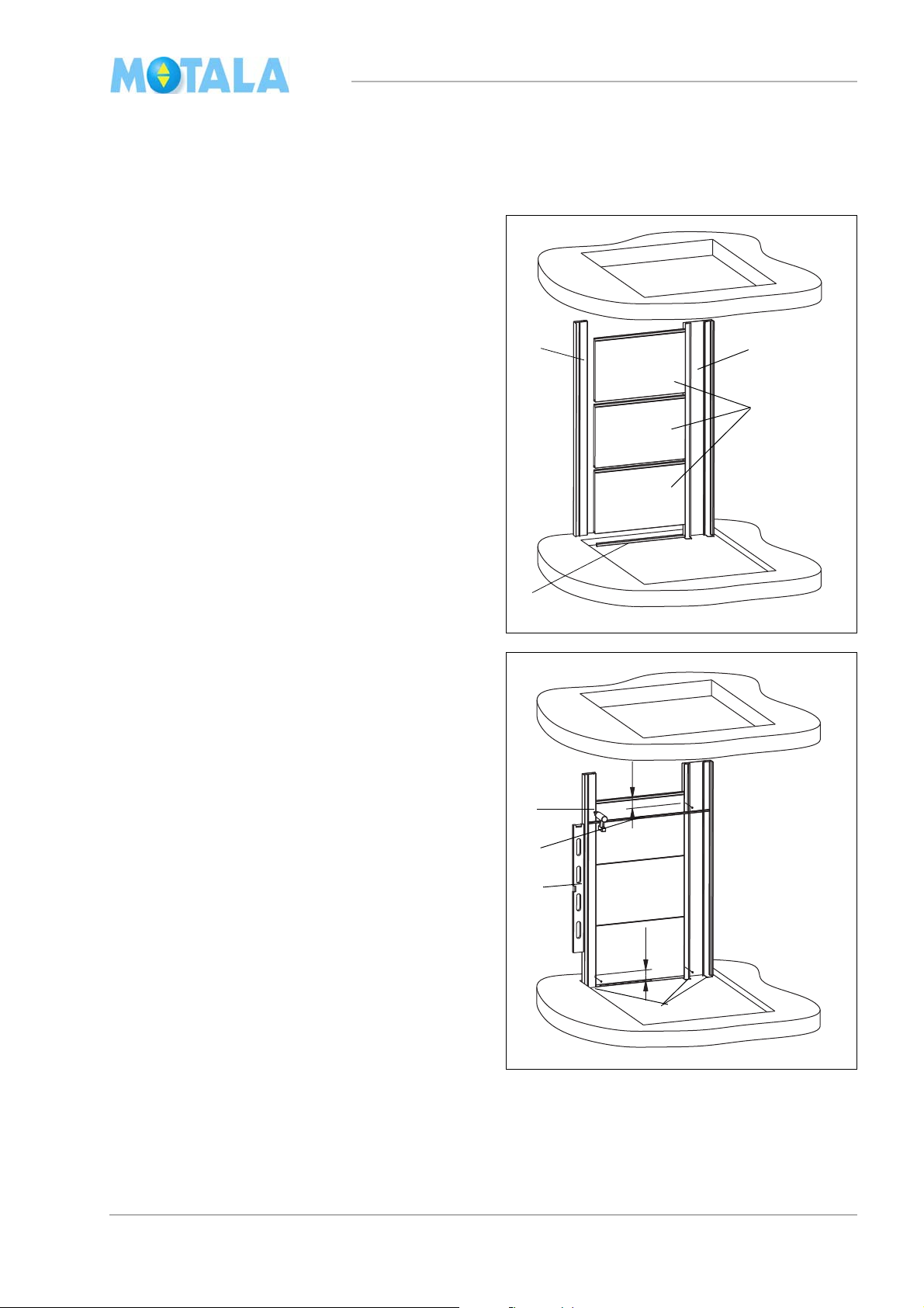
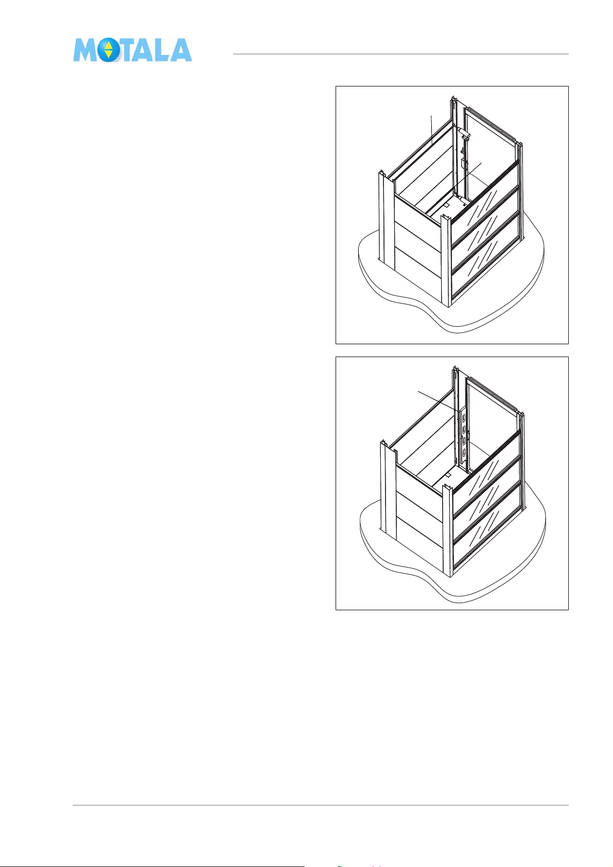
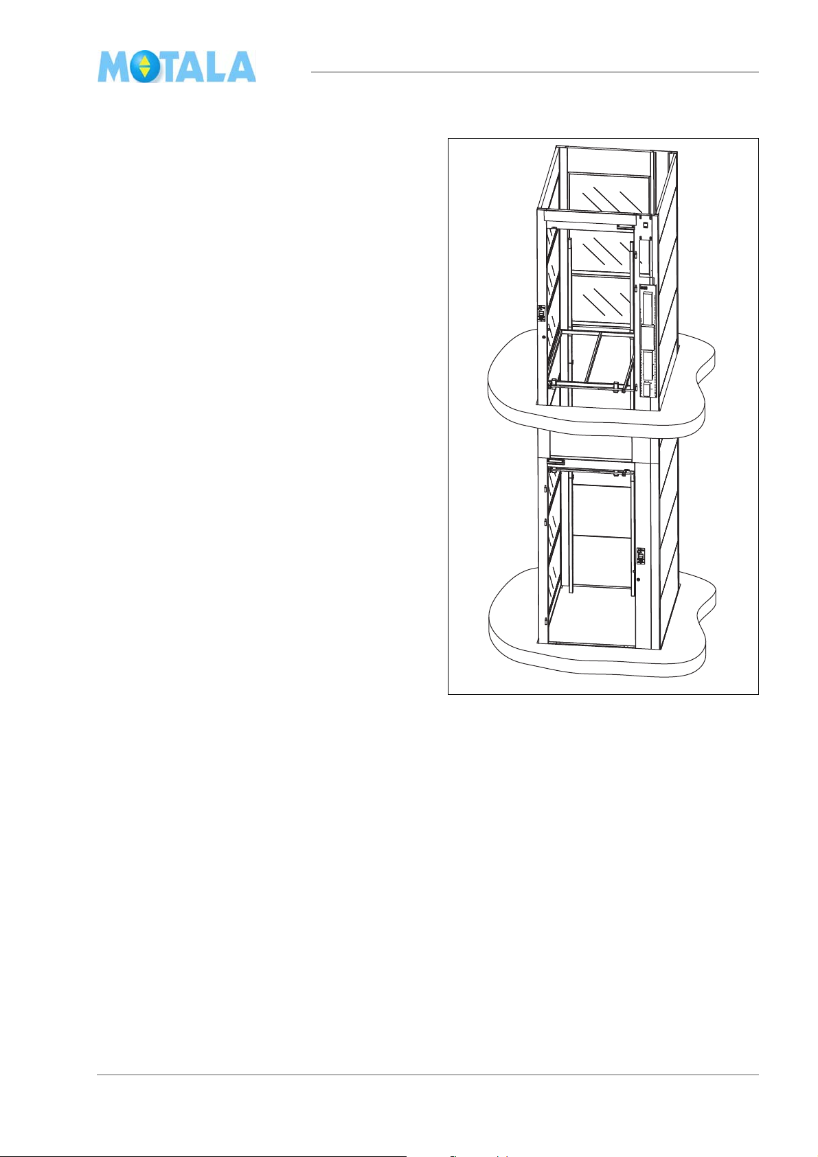
Lift well assembly according to
layout drawing.
Bottom part of the lift well, landing 0
1. Erect the broad corner profile on side C of
the lift well. Note that the broad profile must
be placed against side D.
2. Erect the thin corner profile.
3. Place a U-profile (35 mm) on the bottom
de, “female side”, at the bottom of the
si
lowest lift well module/glass module. The
notches (ends) of the U-profile should be
turned towards the outside of the lift well.
4. Place three lift well modules/glass modules
ween the corner profiles. Turn the “male
bet
side” upwards. The modules must not
reach the very bottom of the corner profiles. Leave a millimetre or two so that,
ater, you will be able to align the whole
l
side C vertically.
5. Place a short dimension stick between the
ner profiles. Check that the base is
cor
level.
6. If necessary, adjust with a metal shim under the corner profiles. The shim must be
aced under the corner profile and the
pl
module. Note! When plumbing, always
start at the “highest point” of the pit.
7. Fasten the modules in the corner profile by
taching one screw at the top and one at
at
the bottom of each side about 100 mm
from the edges. Use a dimension stick.
(For placing of screws, see the heading
“General information on module assembly”
on page 7).
8. Align vertically by means of a long spirit-
vel.
le
9. Fasten the modules and the corner profiles
th screws.
wi
9
MC2000 – Assembly Instruction Manual
10
mc200508
14
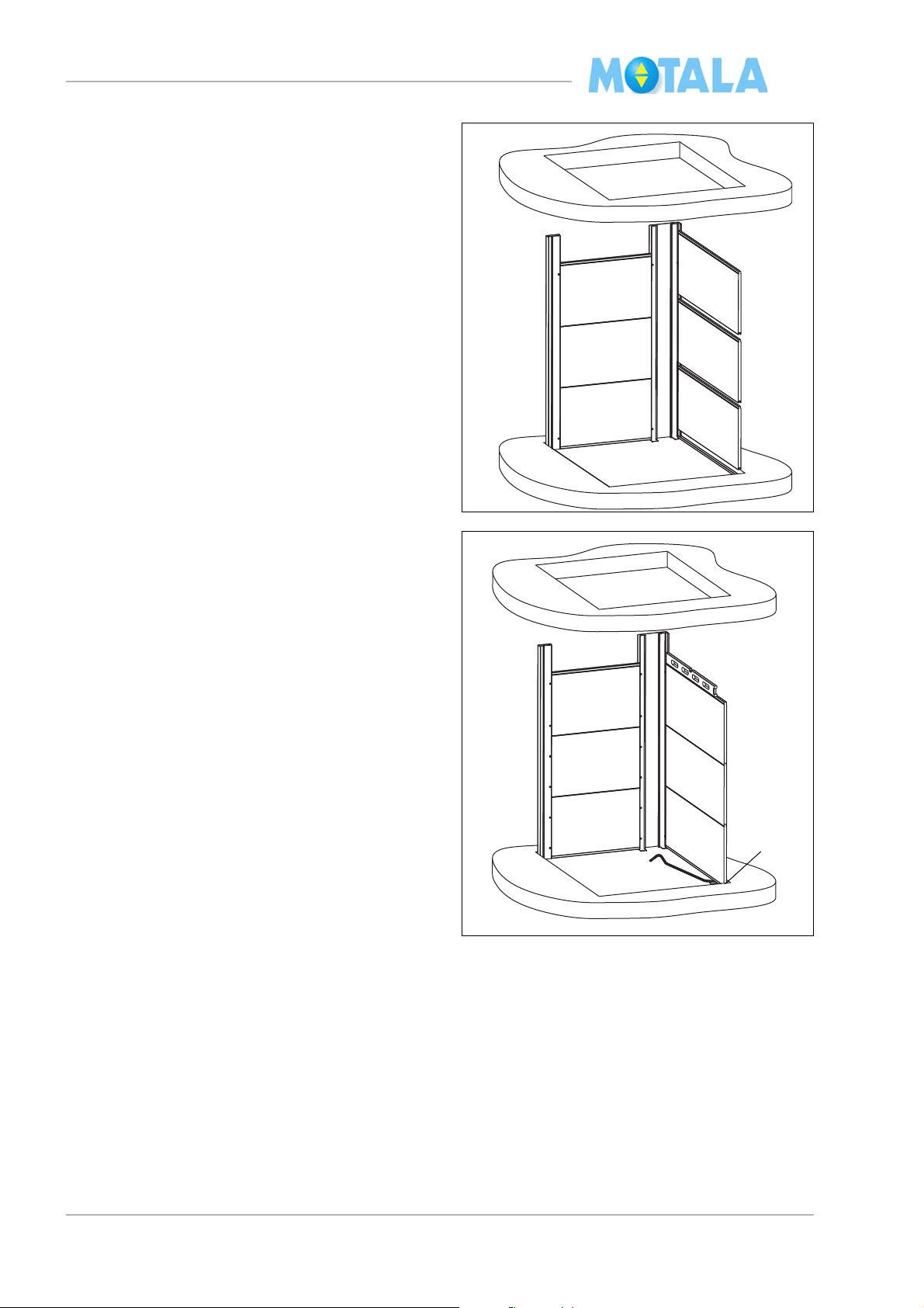
10. Place a U-profile (25 mm) under the lift well
module/glass module on side D. Turn the
notch of the U-profile towards the outside
of the lift well.
11. Place three lift well modules/glass modules
de D. Turn the “male side” upwards.
on si
The modules must not reach the very bottom of the corner profiles. Leave a millimetre or two so that, later, you will be able to
ign the whole side C vertically.
al
12. Fasten the modules in the corner profile by
f
astening one screw at the top and one at
the bottom about 100 mm from the edges.
Note! The screw heads in the corner profile
of the driving side must be placed at least 6
mm from the corner profile to leave room
for the guide rail flange.
13. Align horizontally by means of a spirit-level.
14. If necessary, use metal shims.
10
MC2000 – Assembly Instruction Manual
mc200509
15 17
16
C
D
A
B
18
20
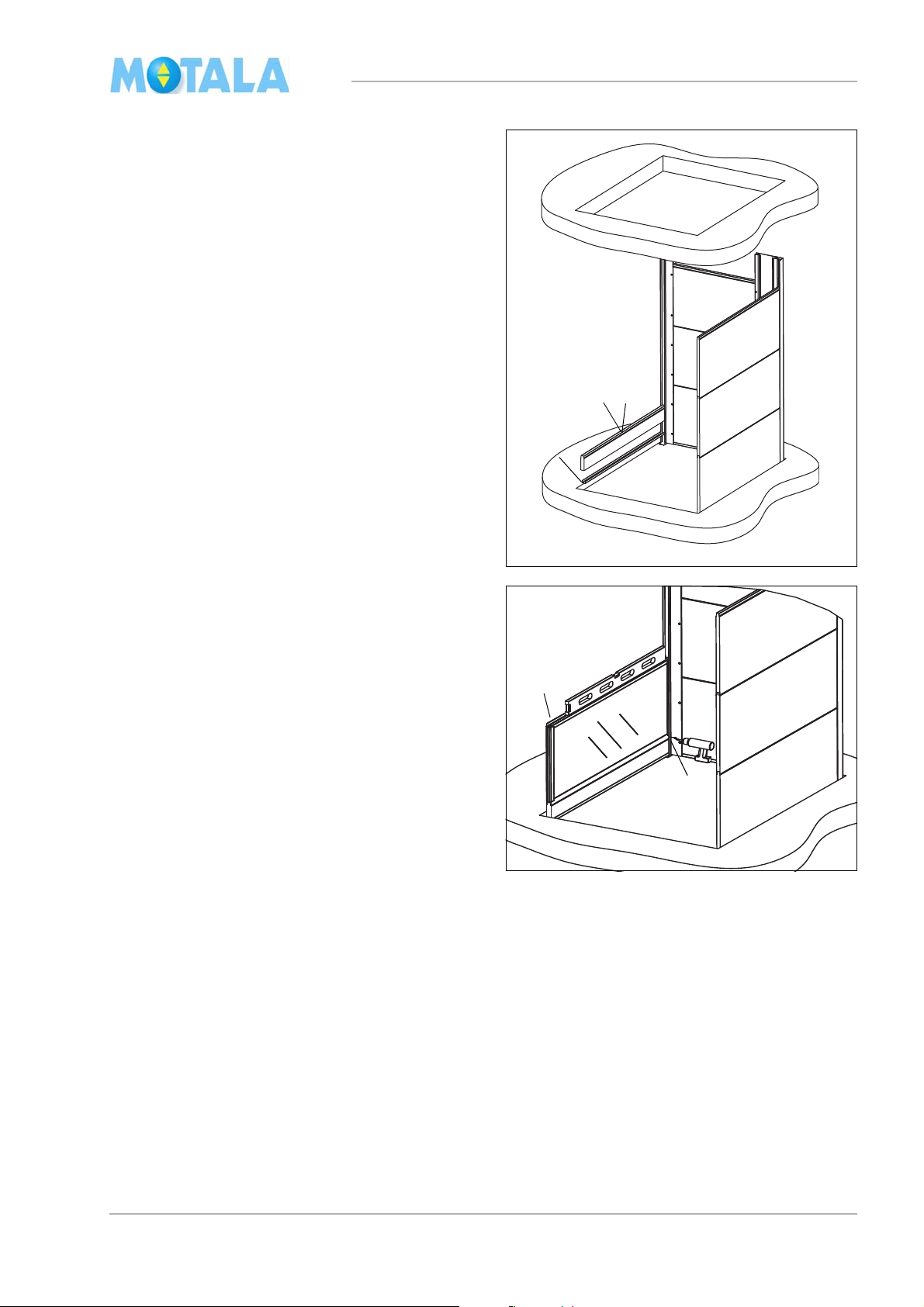
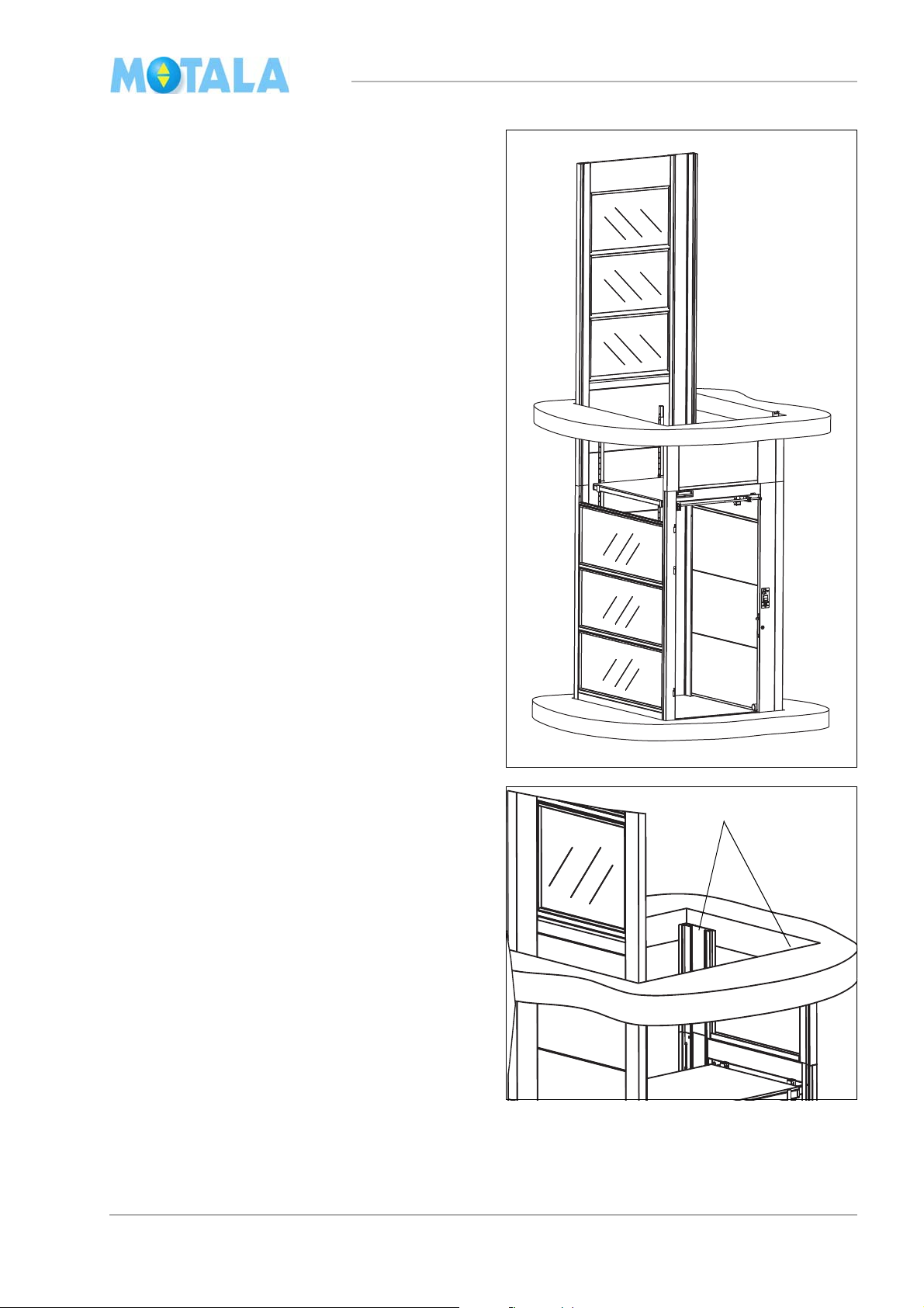
In this example, the lift well side B has glass
modules. The first glass module must not be in
close contact with the pit but should be placed
a little higher up. For measurments, see the layout drawing.
15. Using the male section of a lift well module,
truct a precision gauge block and
cons
place it in close contact with the pit. See
the heading “Construction of precision
gauge blocks” on page 7.
16. Install the U-profile with the notch turned
wards the outside of the lift well.
to
17. Fit the precision gauge block.
18. Place a glass module on top of the preci-
sion gauge block. Turn the “male side” upwards and the level glass side towards the
ift well. Check with a spirit-level that the
l
upper edge of the glass module is horizontal.
19. If necessary, adjust with a metal shim be-
tween the precision gauge block and the
t.
pi
20. Fasten the glass module with a screw in
e longitudinal bottom corner profile. See
th
the heading “Glass module” on page 7.
11
MC2000 – Assembly Instruction Manual
mc200511
22
A
D
C
B
mc200512
23
B
D
C
A
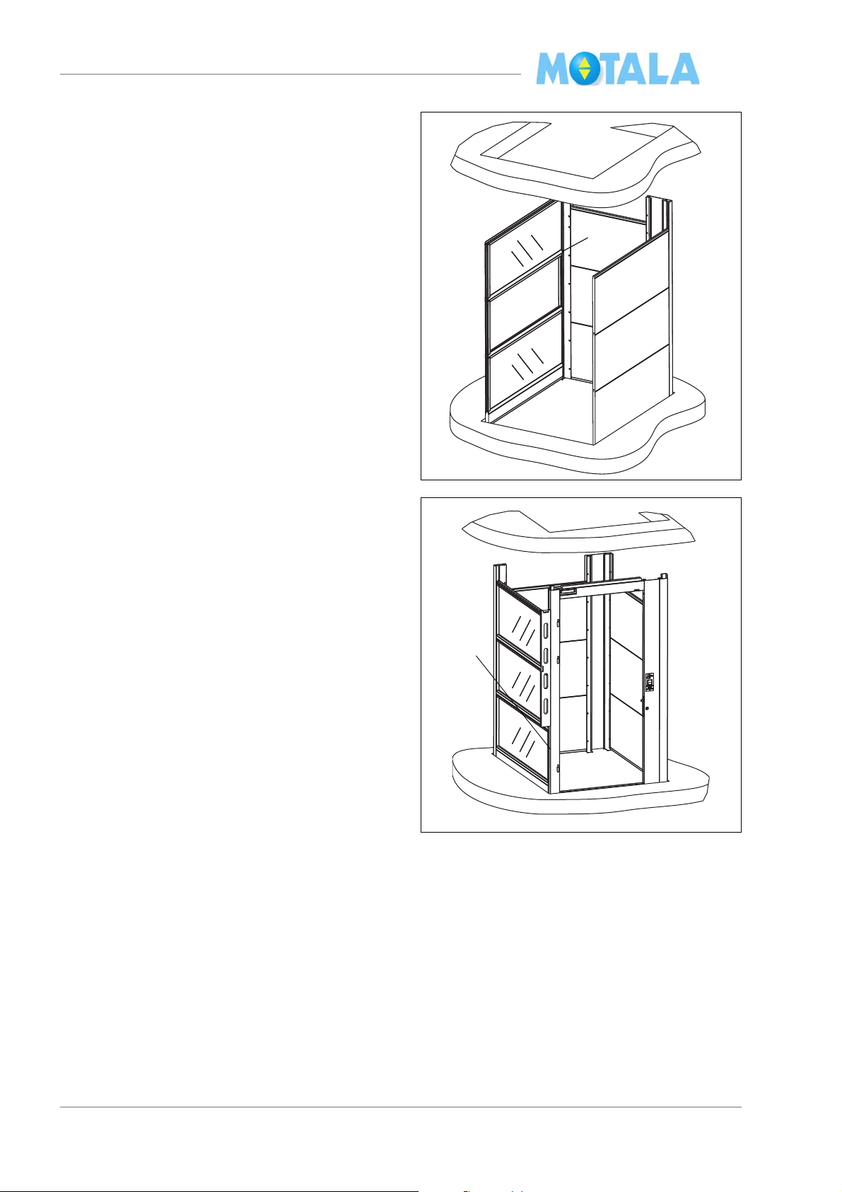
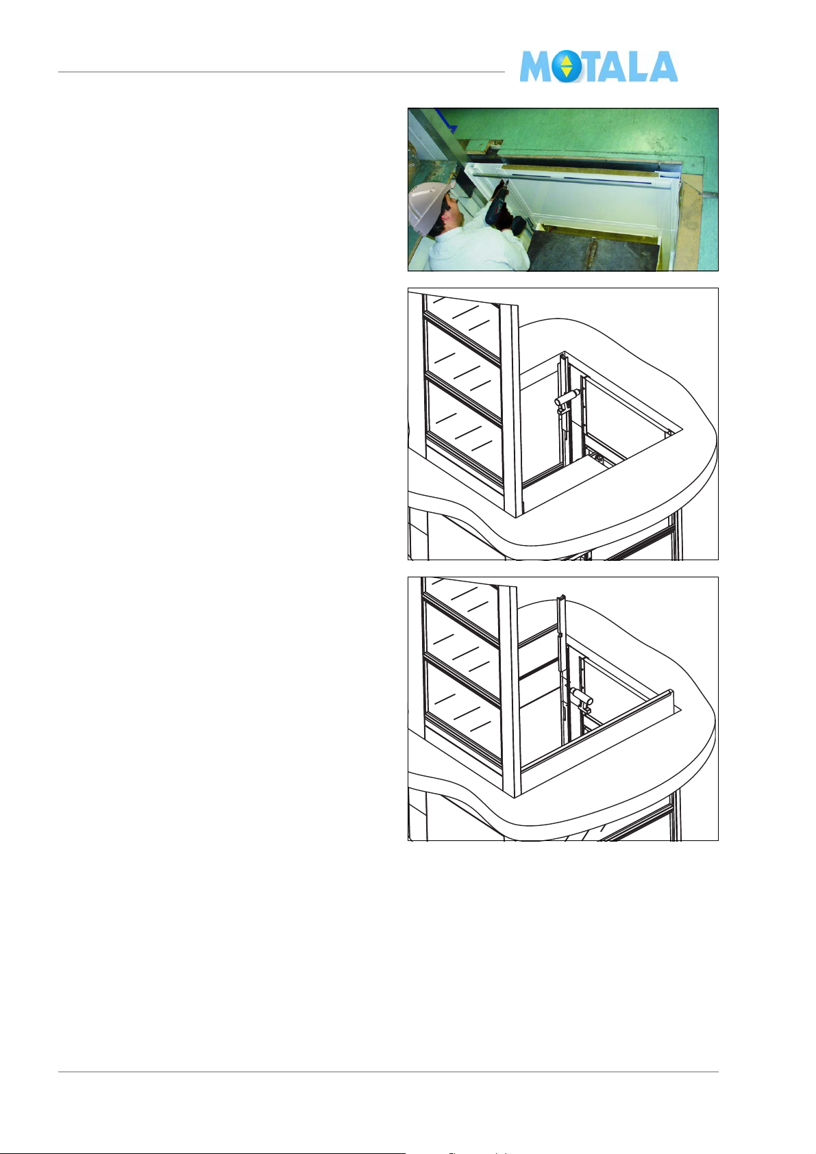
21. Fit three glass modules.
22. Fasten the tops of the glass modules in the
ner profile with a screw through the two
cor
modules.
23. Set up the door frame. Start at the bottom.
Check
is laterally vertical. If necessary, adjust with
metal shims.
with a spirit-level that the door frame
12
MC2000 – Assembly Instruction Manual
mc200513
25
24
A
B
C
D
mc200514
26
24. Use a long dimension stick to check the
correct distance between sides A and C of
the lift well. Fasten the door frame with
screws at the very bottom of the modules
on sides B and D.
25. Move the dimension stick upwards and fasten the door frame with screws in the upper
es of sides B and D.
modul
26. Check with a spirit-level and straighten the
frame vertically against sides A and C.
door
27. Secure the remaining screws in the modules.
13
MC2000 – Assembly Instruction Manual
mc200519A
mc20051
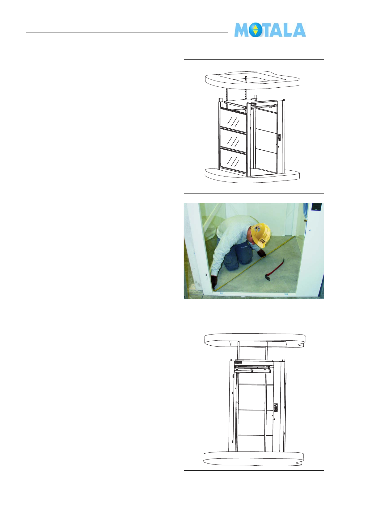
Placing the lift well in the pit
1. Adjust the placing of the lift well in the pit
and chec
k that the lift well can pass freely
upwards through the joists.
2. Measure and adjust the diagonal measurements of the lift well.
Erecting the work platform, landing 0.
1. Erect the work platform in the two predrilled holes of the door frame. Unfold the
platform and set up two adjustable legs in
the back edge of the platform.
14
MC2000 – Assembly Instruction Manual
mc200517
2
mc200518
11
mc200518
2
2
2. Attach the lock pins.
3. Set up the platform floor.
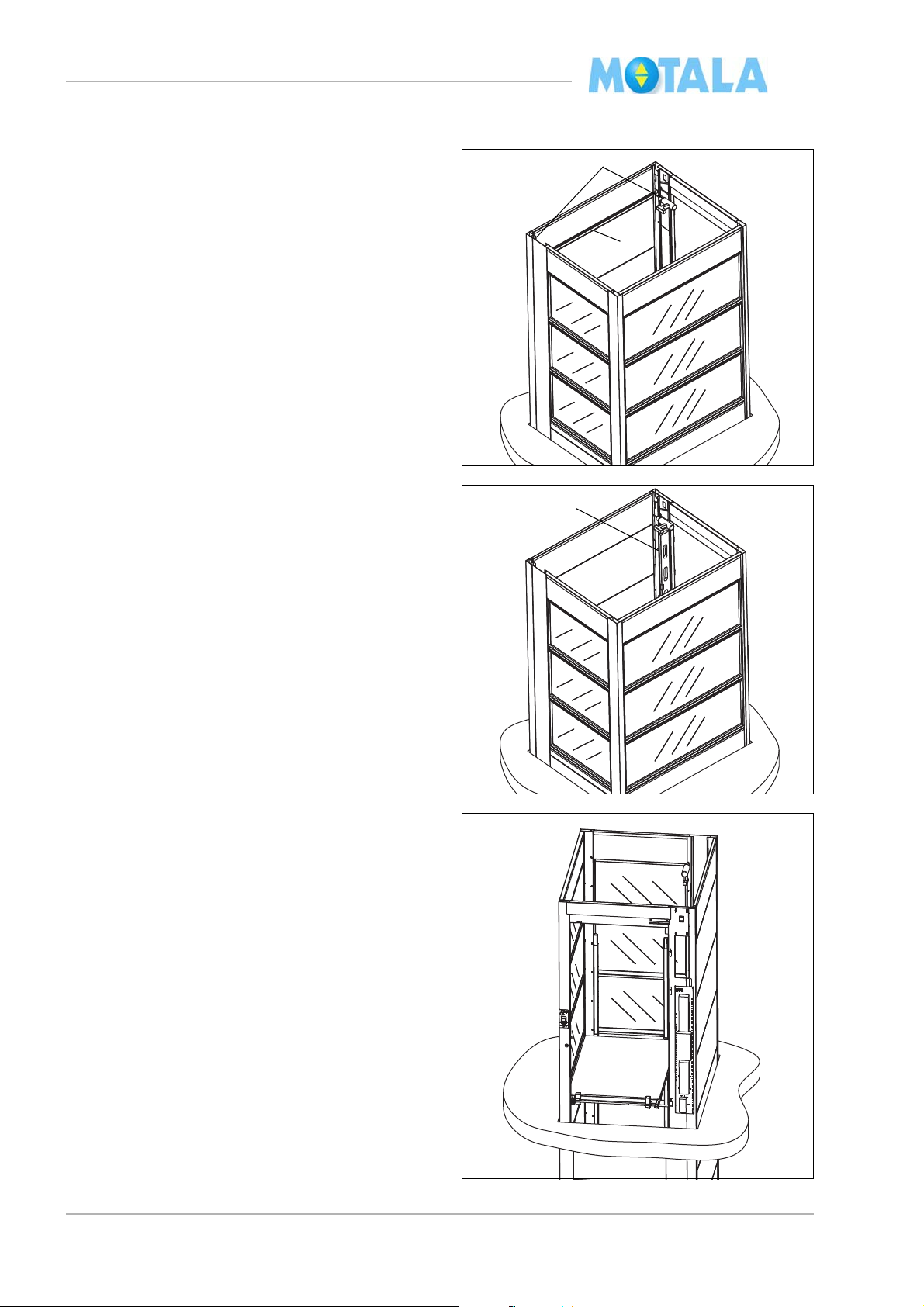
Construction of lift well for remaining floors (1-4)
Corner profiles, side C
1. Fasten a screw in each corner profile of
de C so that half the jointing sleeve de-
si
scends into the profile.
2. Attach the jointing sleeves.
15
MC2000 – Assembly Instruction Manual
mc200519
3. Erect the corner profiles onto the jointing
sleeves
16
MC2000 – Assembly Instruction Manual
mc200521mc200521
7
In this example side C is also fitted with glass
modules and therefore a precision gauge block
is needed for the joist passage and a second
one is needed as a finish at the well top.
4. Construct precision gauge blocks, see the
ng “Construction of precision gauge
headi
blocks”, on page 7.
5. Set up no more than 3 or 4 modules.
6. Align and fasten side C with screws in the
way as you did for landing 0.
same
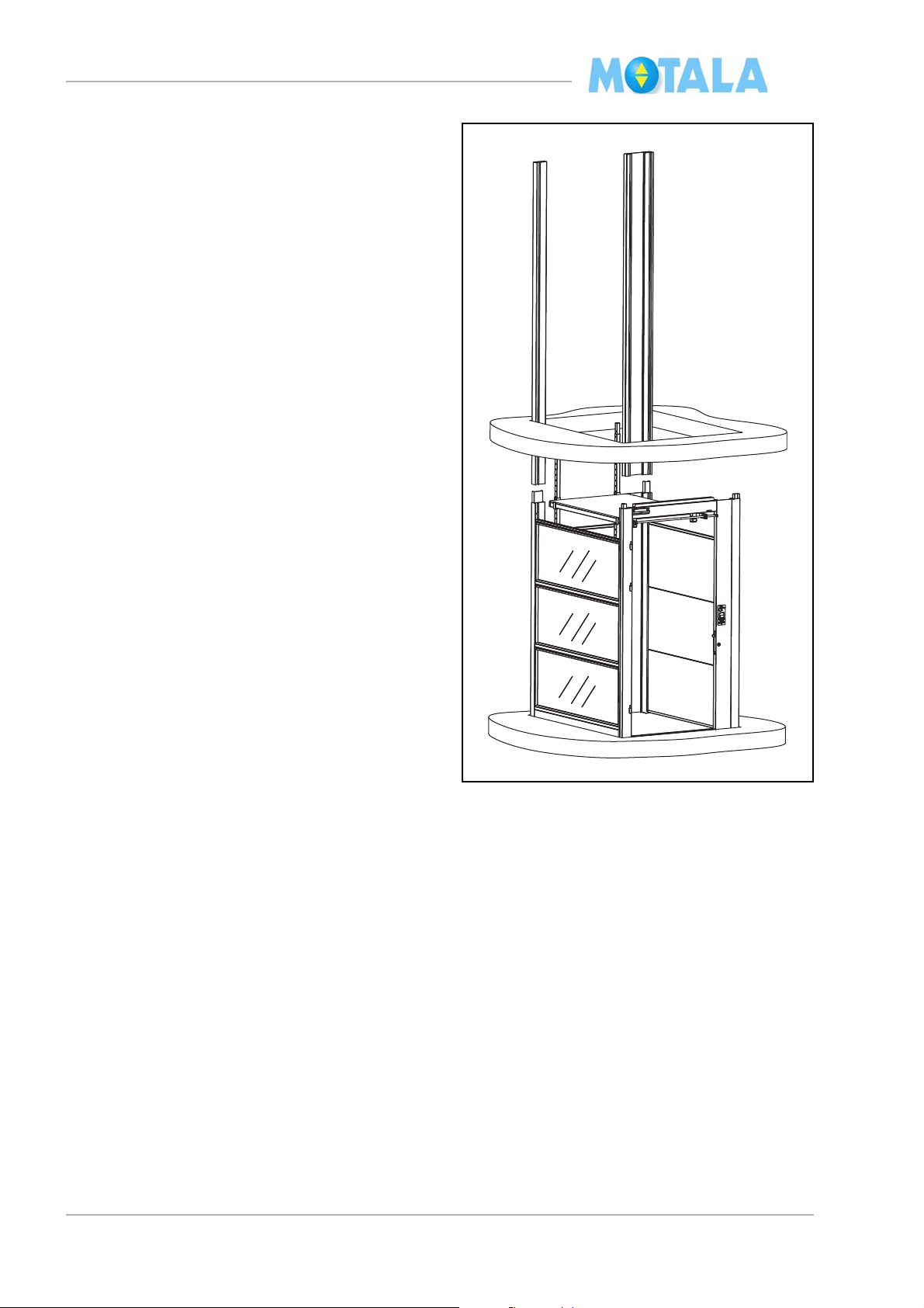
Corner profiles, side A
7. Push the two corner profiles into the door
ame. For length, see the checklist. (The
fr
corner profiles ascend through the joists so
that the door frame of landing 1 can be
placed on top of these profiles.)
17
MC2000 – Assembly Instruction Manual
A
B
C
D
A
B
D
C
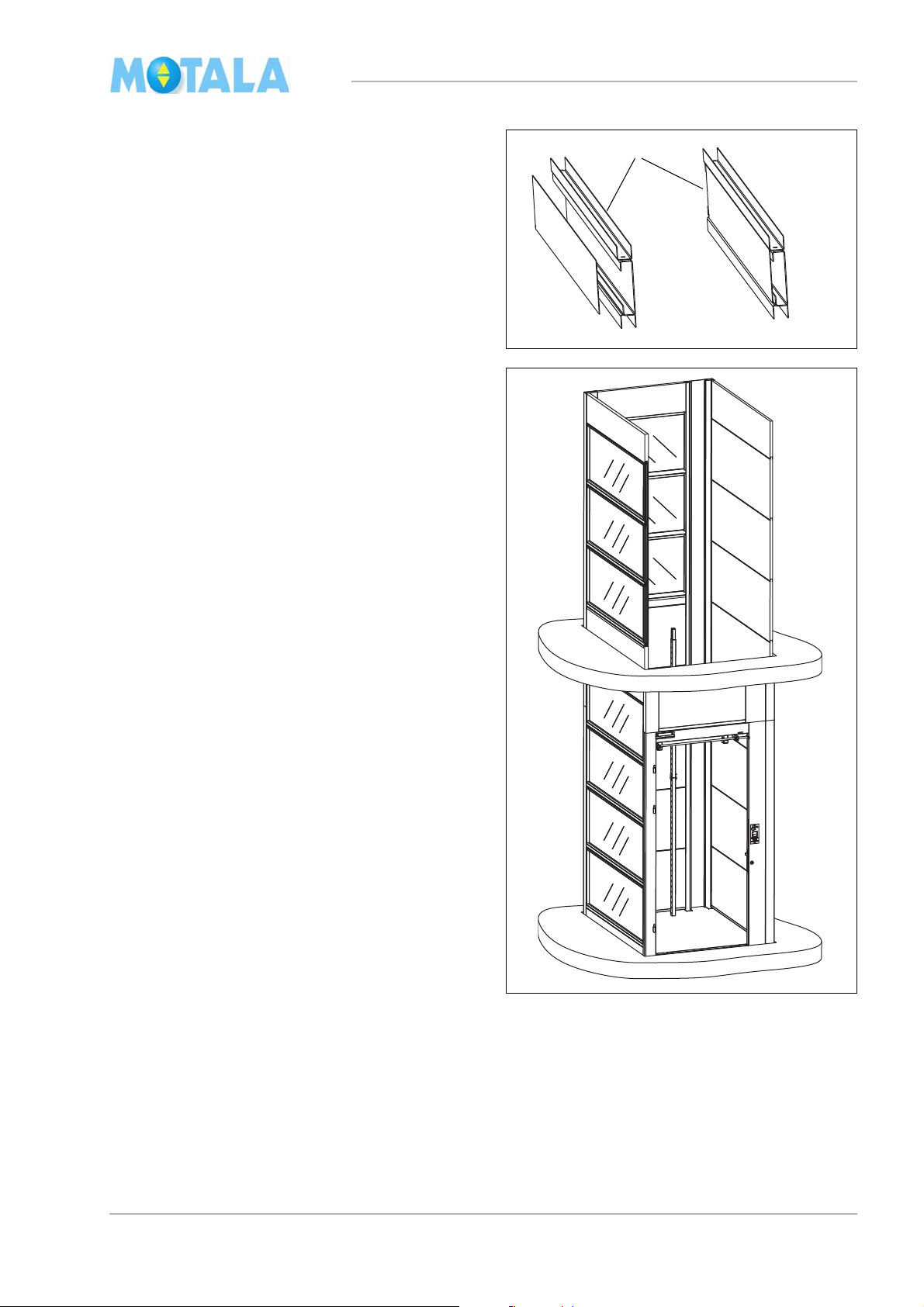
8. Measure and cut the lift well module with a
jigg saw if necessary. The module should
end a few millimetres below the upper ends
of the corner profiles.
9. Assemble the module/modules.
10. Use a short dimension stick and fasten the
modul
of the corner profiles.
11. Use a spirit-level and fasten the remaining
s
e with two screws in the upper edges
crews in lift well wall A.
12. Erect the modules on sides B and D. Use a
ong dimension stick and fasten the mod-
l
ules with two screws in the upper edges of
he corner profiles. Use a spirit-level and
t
fasten the remaining screws in lift well walls
B and D.
18
MC2000 – Assembly Instruction Manual
mc200548
13
mc200545
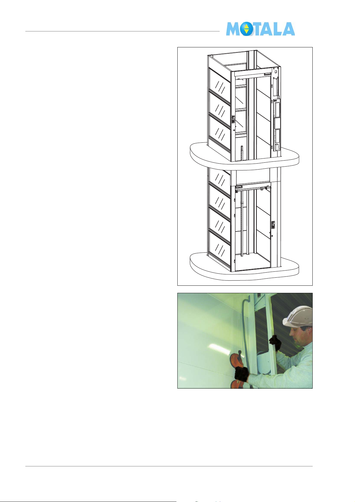
13. Note! For adjacent lifts and two-entrance
lifts, remember that you need a channel for
cables and wires in the lift well walls. The
retiring ramp is always on the same side as
the motor and the gear, see “Layout drawing” on page 48.
14. Install the modules on sides B and D.
15. Cut the modules about 2 mm shorter than
e corner profiles.
th
16. Set up the U-profiles.
17. Fasten the sides with screws just as you
d on the previous floor.
di
19
MC2000 – Assembly Instruction Manual
mc200525
18. Install the door frame in the two foremost
corner profiles.
19. Unfold and fit the door frame against the
modul
es of sides B and D. Use a glazier’s
lifting tool with suction cups.
20
MC2000 – Assembly Instruction Manual
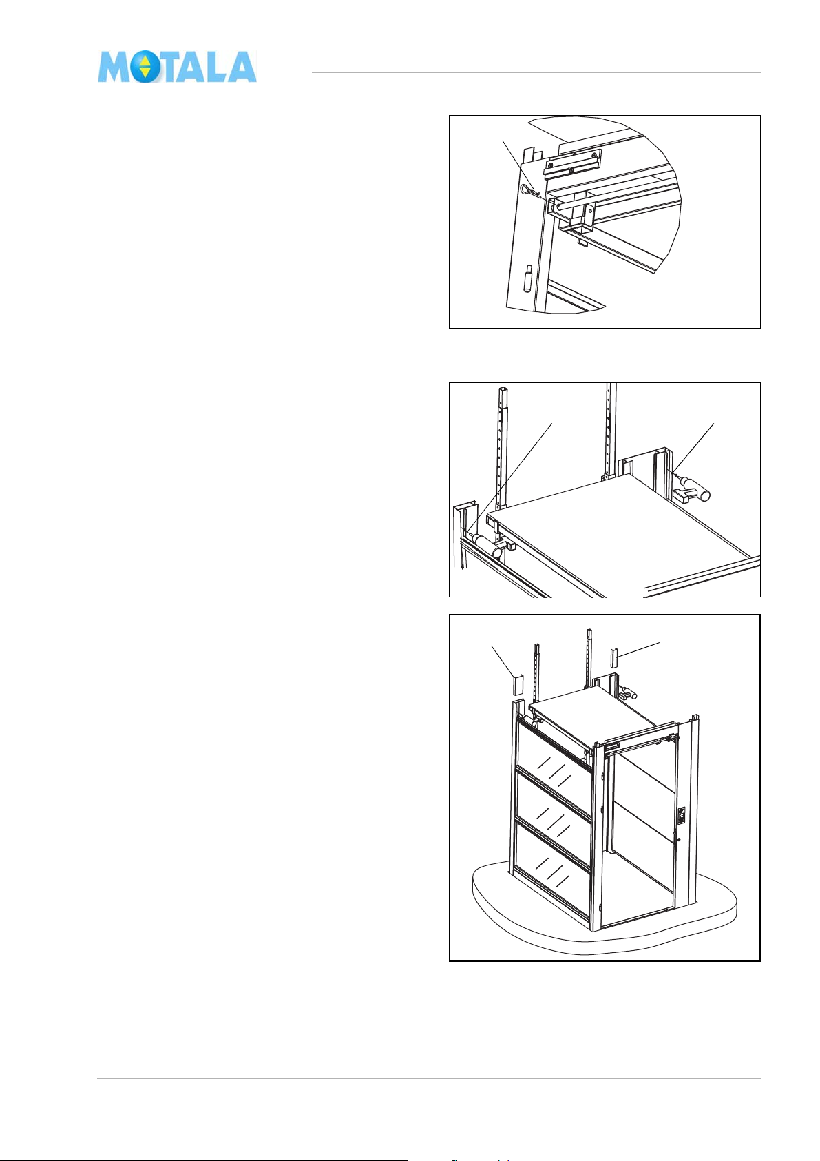
mc200526
Erecting the work platform, landings 1-4
1. Erect the work platform in the two preilled holes of the door frame. Unfold the
dr
platform and set it up in the two adjustable
legs in the back edge of the platform.
2. Attach the lock pins.
3. Install the platform floor.
21
MC2000 – Assembly Instruction Manual
2
1
3
Finishing the upper part of the lift well
Straightening of sides B and D
1. Place the dimension stick on a level with
he upper edge of the door frame.
t
2. Fasten a screw in the upper part of the
frame and another screw on the same
door
level on side C.
3. Align side A with a spirit-level and fasten
t
he remaining screws.
4. Align and fasten the other side in the same
.
way
5. Erect the remaining modules on side C and
sec
ure them with screws. Use a short di-
mension stick.
In order to place the last lift well modules/glass
es on side C in case of minimal roof
modul
space.
• Unfasten the module screws temporarily.
• Pull the corner profiles apart so that the
module
ner profiles.
• Fasten the modules with screws.
s can be placed in between the cor-
22
MC2000 – Assembly Instruction Manual
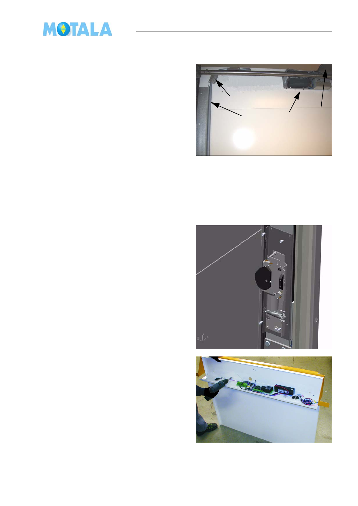
127:
Installation of electric cables and wires
Pull all the cables to the control panel, i.e. the
e from the pit and the cables from all the
cabl
door frames.
The illustrations show the standard installation,
e. the control panel is installed on the door
i.
frame on the top floor at the same place as the
motor and the gear.
If the control panel is placed on another floor on
side the lift, cables for the hand wheel
or out
contact 28: must be installed; the motor cable
and the brake cable to the control panel. (The
hand wheel contact is effected by the hand
wheel tool for emergency control of the lift.)
Also see on page 28.
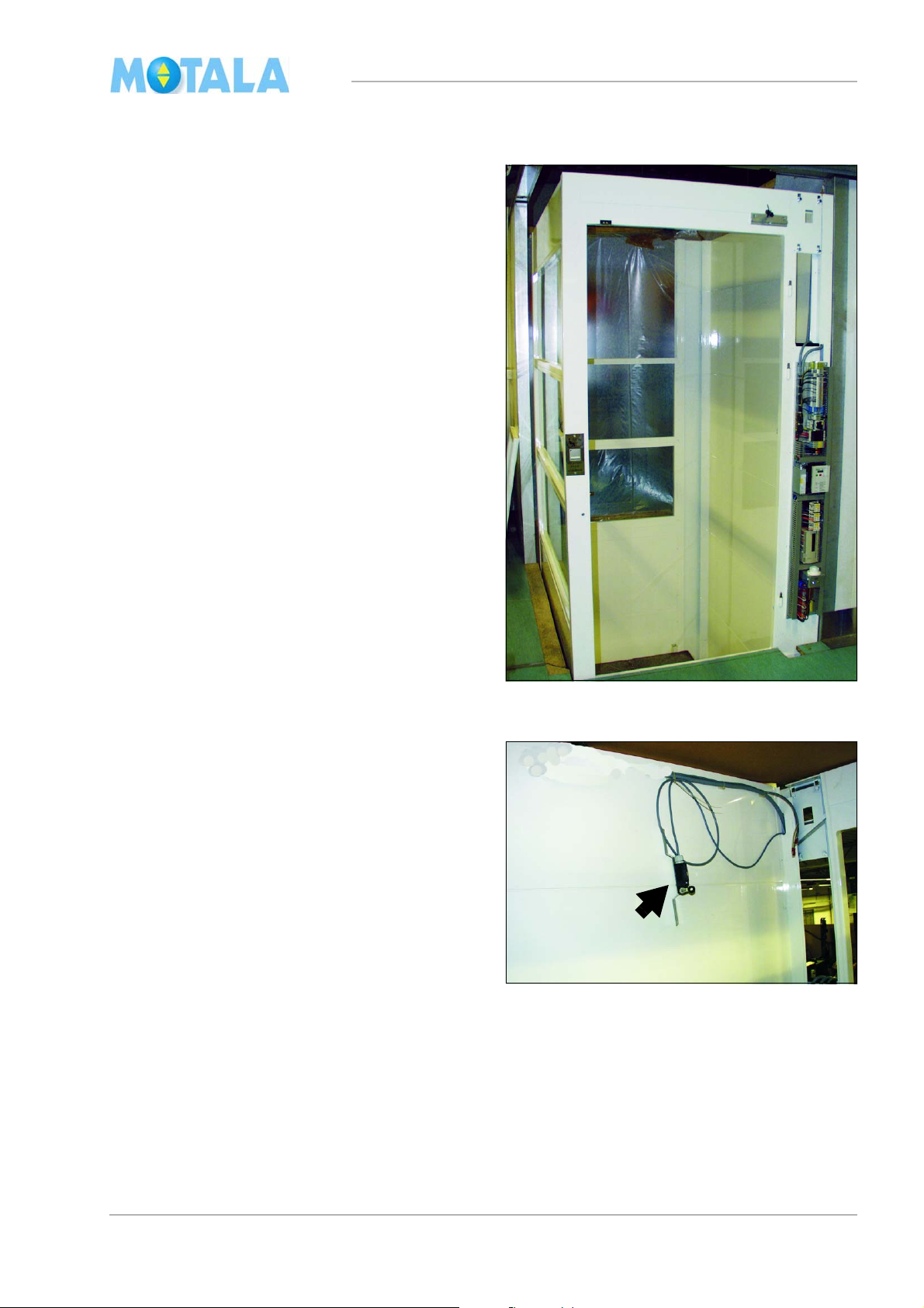
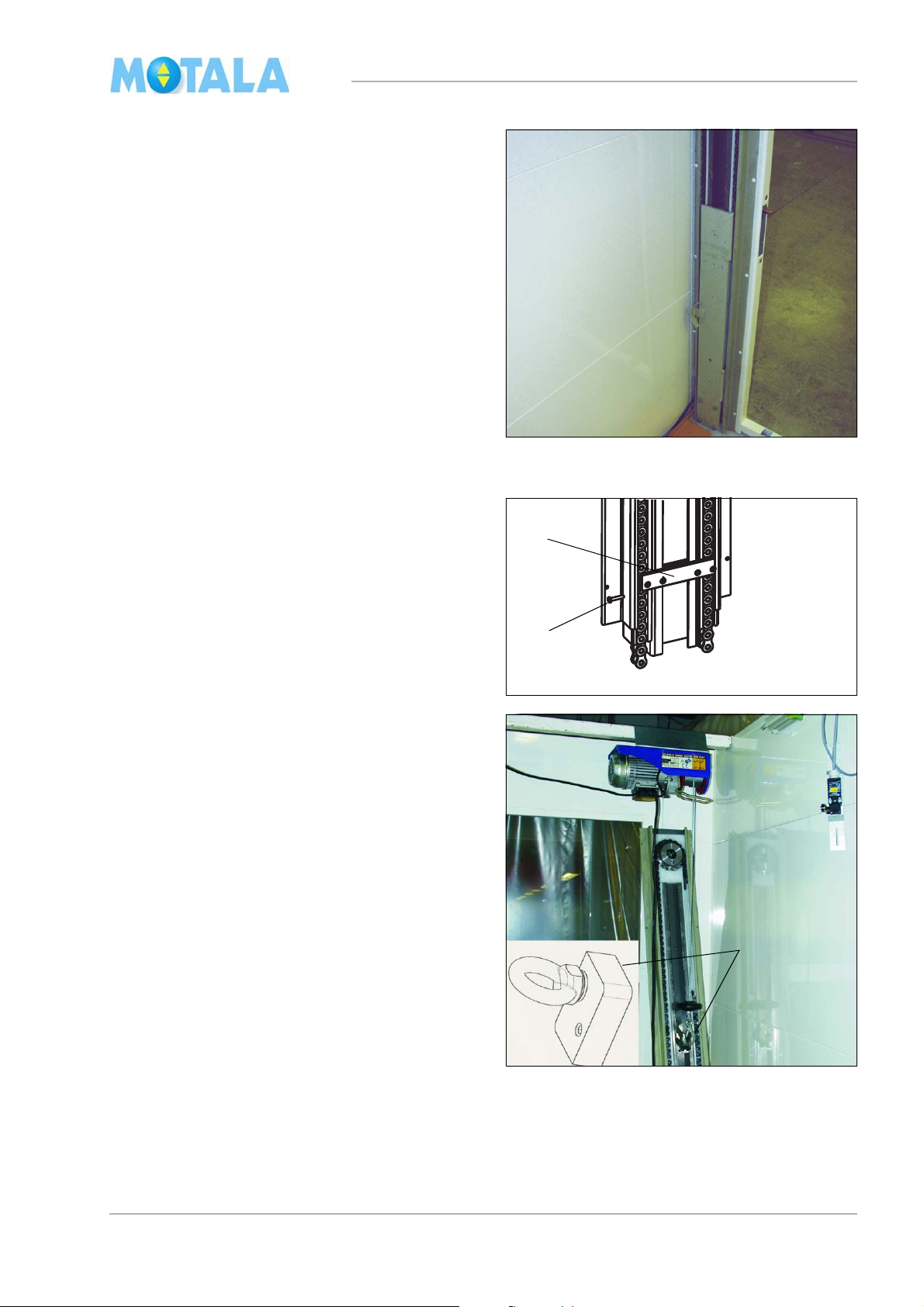
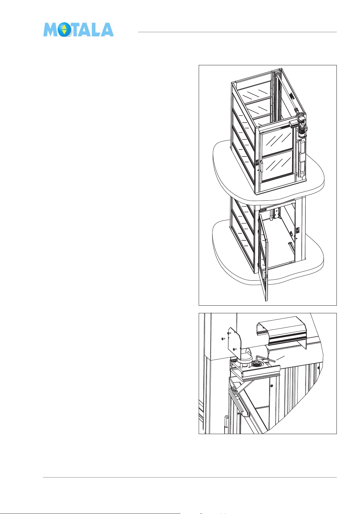
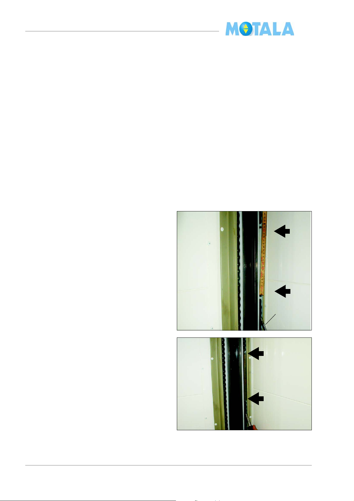
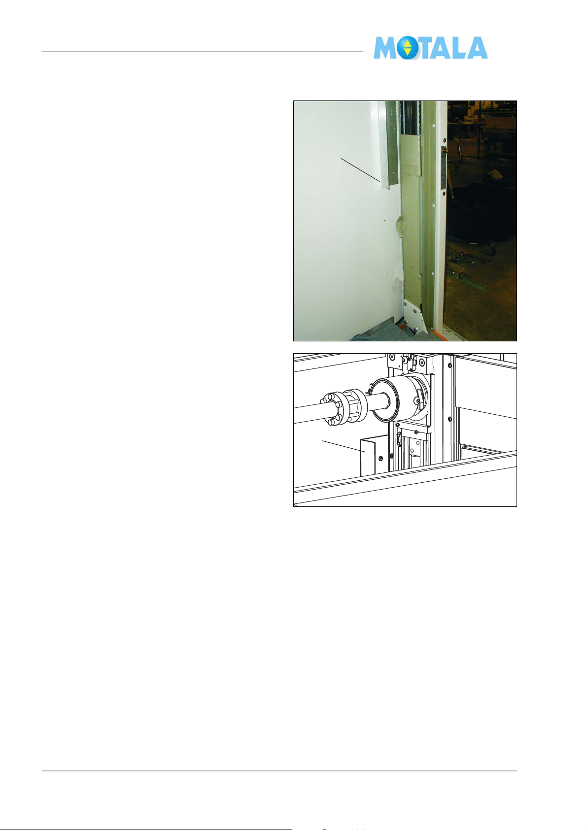
Top landing
1. Route the cable for the safety gear contact
127: to the control panel (to be installed
later) with cable tie
2. .Temporarily fasten the upper end limit
U (marked with an arrow in the photo)
62:
and pull the cable through the door frame
to the control panel.
3. Note where the cables from the door
ames enter the channel so that you do not
fr
screw or drill through them by mistake. Try
to keep the cables in the centre of the door
frame profile and the corner profile.
23
MC2000 – Assembly Instruction Manual
1
2
1
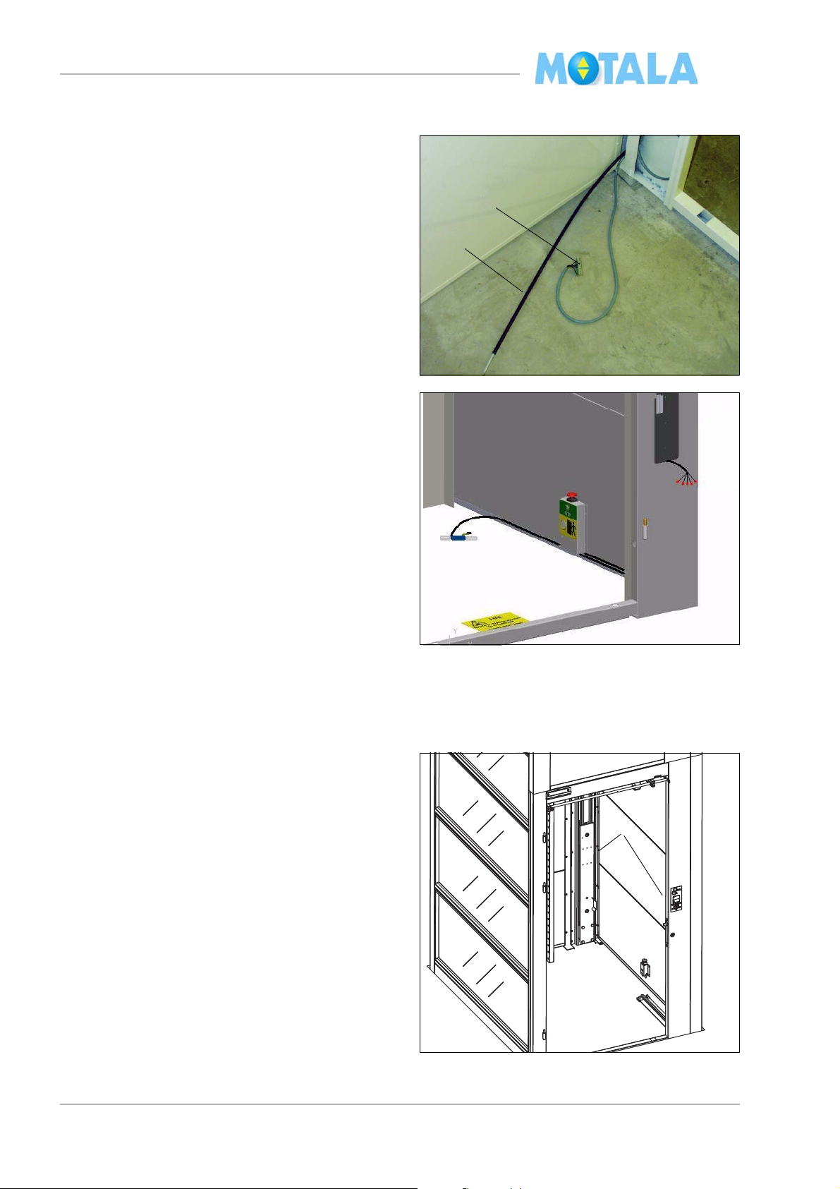
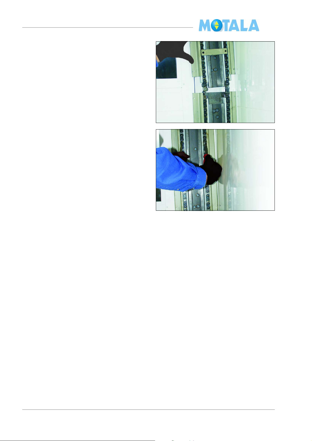
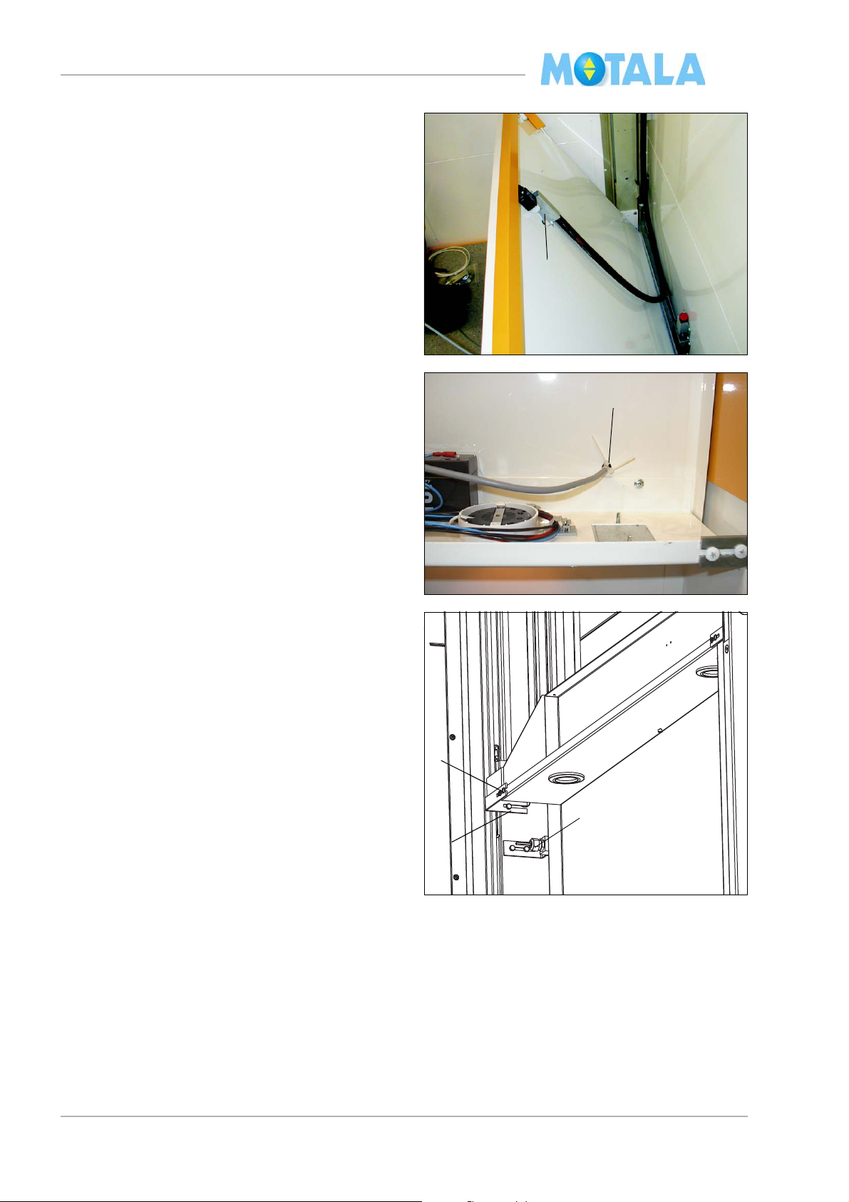
Landing 0, pit
1. Pull the cable with terminal block “control
anel - terminal block pit” through the
p
opening in the door frame. (Length of cable
to the block approx. 0.8 m.)
2. Pull the door lock wire through the same
ing.
open
3. Install “terminal block with the stop button”
and cabe
switch 62:U on the side wall of the driving
side in the lift well. It should be placed in a
position of 100mm from centre nearest
door side, about 50 mm upwards on the
wall.
4. Route the cable for the pit prop into the cor-
ner profile and out where the recess for the
t prop is. The end limit and the pit prop
pi
shall be fitted later.
l for the pit prop and end limit
Guide rails
Lower guide rails
1. Place the lower rails in the lift well. Note the
markings A and C. Side A is always the
side where the motor and the gear are
placed.
24
MC2000 – Assembly Instruction Manual
mc200529
1
2
6
2. Place the guide rails in the very corners
th the mounting brackets turned towards
wi
the lift well wall. Check that the lower end
of the guide rail is on the same level as the
lower edge of the lift well, i.e. take the
shims, if any, into consideration
3. Secure the guide rails with screws. Note!
Use 25
mm screws. Check that you do not
screw through any cable or door lock.
Upper guide rails
1. Install the chain fixing device.
2. Remove the two plate screws (transport
ocking) that keep the chain in place in
l
each guide rail.
3. Erect the adjustable mounti
ng rod between
two of the walls of the lift well.
4. Attach the lifting winch to the mounting rod.
5. Lift the guide rails into the lift well.
6. Install a lifting loop on one of the guide
ils.
ra
7. Lift the guide rail. Check that it is installed
n its correct position, see the marking in
i
the guide rail profile..
25
MC2000 – Assembly Instruction Manual
8. Joint the chains. Lift the guide rail that is to
be jointed high enough above the lower
guide rail so that you can attach the connecting links.
9. Hold the chains in the upper guide rail with
g. two screw drivers and loosen the chain
e.
fixing device at the same time. Lower and
adjust the guide rail. Work carefully and
check that the steering pins enter the top
track properly.
10. Fasten the guide rails in the lift well with
rews. Use 25 mm screws. Check that the
sc
two C-profiles of the guide rails are in a position exactly opposite each other, so that
he lift moves softly past the joint.
t
11. Perform the same operation with the remaining guide rails..
26
MC2000 – Assembly Instruction Manual
mc200530
1
2
mc200531
3
20mm
4
mc200532
7
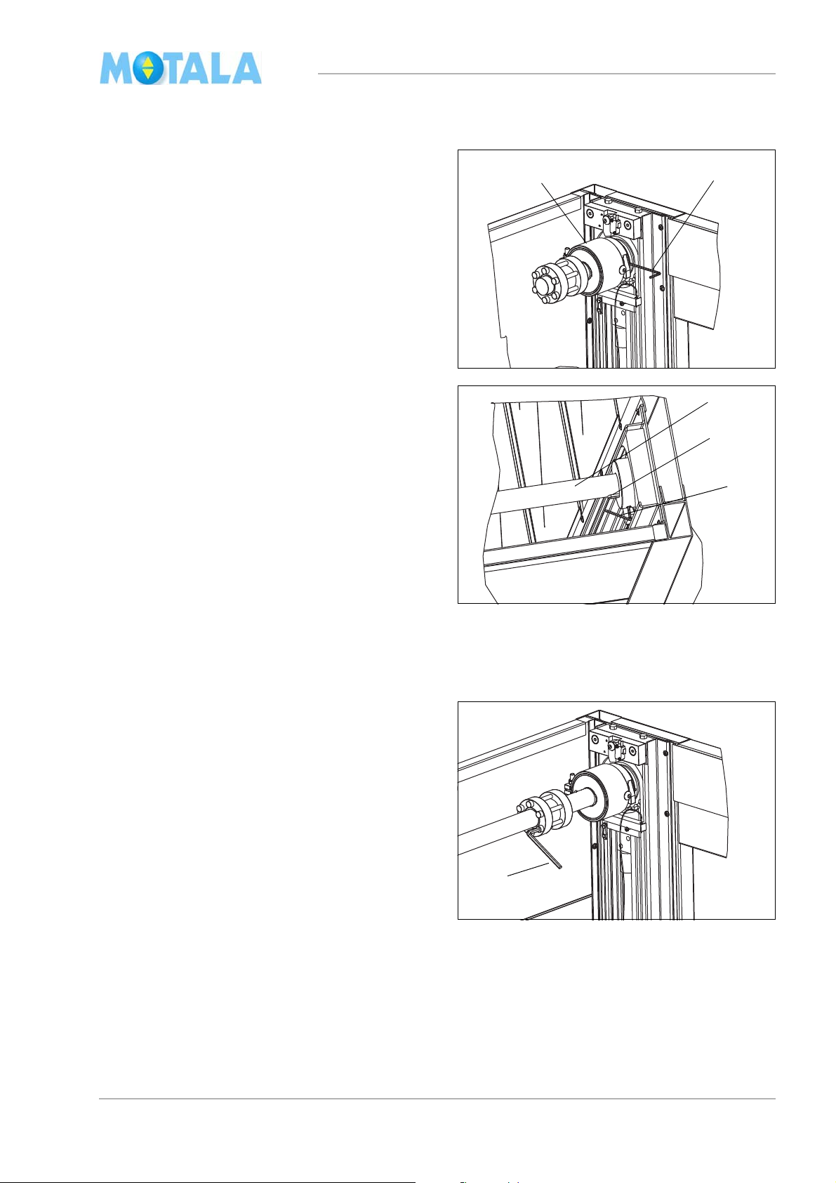
Driving shafts, gear and motor
1. Carefully push the safety gear shaft into the
sprocket wheel on side A of the lift. Note!
Do not use force!
2. Fasten the lock screw (use a 3 mm socket
ch).
wren
3. Carefully insert the long driving shaft into
si
de A. Check that the shaft reaches the
very bottom of the sprocket wheel bearing
in the turning case. Maximally 20 mm of the
keyway should be seen. Note! Do not use
force!
4. Fasten the lock screw (use a 4 mm socket
ch.)
wren
5. Loosen the four M10 screws (transport po-
sition) on each slide so that the shafts can
ned by hand. (Note! These screws
be tur
will be needed later for platform fitting.)
6. Measure and adjust the chain joints of the
two gui
de rails so that they are at the same
distance from the turning case.
7. Pull the shaft coupling tight crosswise (use
6 mm socket wrench 41 Nm).
a
27
MC2000 – Assembly Instruction Manual
10
9
mc200534
11
mc200535
28:
8. Thread on the test device cord of the safety
gear through the hollow space between the
guide rail and the door frame.
9. Fit the two keyways on the short driving
ft before installing the motor package.
sha
10. Change the oil plug at the top of the gear
or the enclosed plug with vent holes.
f
11. Tie the test device cord of the safety gear
n an empty screw hole on the gear.
i
12. Fasten the hand wheel contact 28: with
rews. The contact must be activated be-
sc
fore the hand wheel tool enters the teeth.
28

MC2000 – Assembly Instruction Manual
Connecting pit functions
Connect the cables according to the electrical
diagram of the lift. The bottom floor is called
“landing 0” in the diagram.
1. Fit temporarily and connect the terminal
oor switch (marked with an arrow in the il-
fl
lustration). The friction roller should be
aced at least 40 mm from the outer edge
pl
of the guide rail. (The position is to be adjusted later).
2. Fit and connect the pit prop, contact 155:1
and the
electrical drawings
3. Fasten all cables in the side wall of the lift
wel
4. Fit the pit prop cover.
position contact 155:2. See in the
l.
29

MC2000 – Assembly Instruction Manual
Connecting control panel wiring
1. Connect the cables in the control panel according to the electrical diagram.
• Do not cut the cables too short.
• Unload the cables with cable tie.
• Import
ant! Make sure there is no lead
connected to terminal input 15 on the
PLC! Impulse function!
Connecting drive command box
Safety
Use the approved drive command box from
Motal
a Hissar (with emergency stop).
Note! For your own safety and that of other
ons, disconnect the control voltage for
pers
the call buttons, connected to terminals X1/
47 and X1/48. See the electrical drawings.
1. Connect the emergency stop to block X1/3
and X1/
10 in the controlpanel. Important!
This is the same terminals where the
platform safety contacts will be connected later. The command box shall be
sconnected before connect the plat-
di
form safety leads.
2. Connect the lift drive wires. Connect the
ply to terminal X1/24V, upwards drive to
sup
X1/42 and downwards drive to X1/41. See
the electrical drawings.
x
30
MC2000 – Assembly Instruction Manual
mc200536
mc200544
8
Door panel and removal of work platform
1. Secure the door openings so that nobody
can accidentally fall into the lift well.
2. Install all the sills loosely except on landing
here the sill should be fitted properly af-
0 w
ter fastening the lift well.
3. Hang up the doors.
4. Remove the work platforms and close the
s as the platforms are being removed.
door
5. Adjust the doors and the lock box. (There
d be an approximate play of 1 mm.)
shoul
Adjust by loosening the screw above the
lock box, push the loose wedge upwards or
downwards.
6. Fasten the screw.
7. Install the door closer or electric door
opener
, with the exception of landing 0
where only the door panel should be fitted.
The door closer is fitted after the fastening
of the lift well.
8. The electric door opener moment is factory-set.
The adjustment of door opening times for electric door openers is made later. See separate
tructions in the electrical diagram.
ins
31
MC2000 – Assembly Instruction Manual
2
Commencing with drive command box
1. The safety circuit must be whole in order to
drive, i.e. stop circuit, door circuit, lock circuit etc.
2. Switch on the supply voltage.
3. Check that the slides of the platform goes
n the right direction in relation to the con-
i
tactors. If they go in the wrong direction,
nge motor phase.
cha
The lift will only go down after the current
has been discone
The lift has PLC control, so you can only drive
landing 0 the first time, in order to reset the
to
PLC program after the current has been disconnected. You may need to adjust floor 0 limit
tch now.
swi
cted!
Chain jointing rod
1. With the drive command box, drive the
slides almost to the top so that the chain
ends are reachable from landing 0.
2. With a big screw driver, press the lower
of the chain upwards. Measure the de-
end
sirable length of the jointing rod.
3. Measure and drill a new hole (diameter 6.0
mm) in t
ends.
4. Fit the jointing rod with connecting links.
5. Perform the same procedure on the other
cha
6. Drive the slides down.
he jointing rod. Cut and bevel the
in.
32
MC2000 – Assembly Instruction Manual
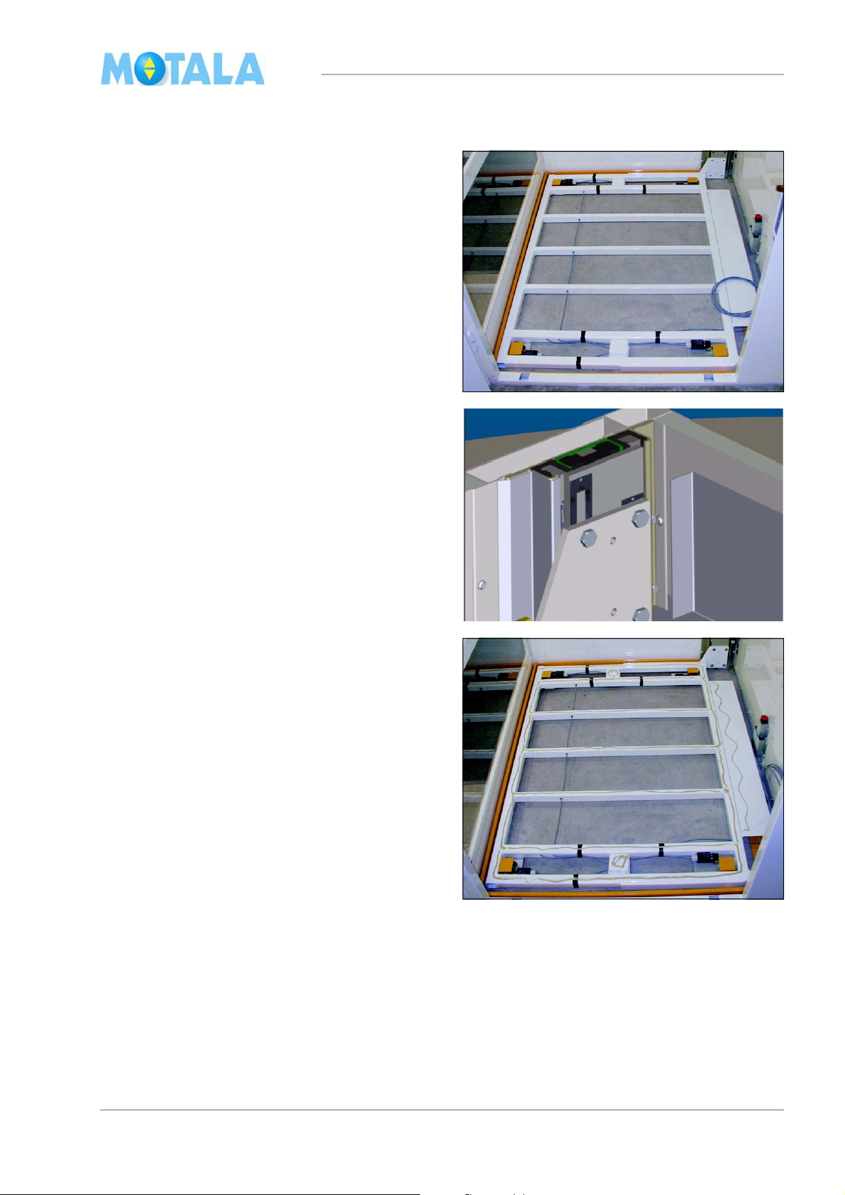
Platform
1. Lift the floor panel from the floor frame.
2. Carry the floor frame into the lift well and
ld it downwards.
fo
1. Fasten the floor frame in the slides, using
ght M10 screws. Lift and adjust the floor
ei
frame into position with a crowbar so that
the screws can be fastened lose by hand.
2. Fit if nesisary schims “in pairs between”
atform fixing and slide. If yo need to put
pl
more than one pair of shims to fill up the
gap, you shall share them equal only in
pairs to both fixings.
3. Fasten the screws with 55 Nm
4. Put an adhesive run on all the floor frame
ossbars.
cr
33

MC2000 – Assembly Instruction Manual
3
4
5
5. Install the floor panel. Check that the bentdown edge of the floor panel is in close
contact with the floor frame.
6. If necessary, fine-adjust the diagonal
measur
e of the lift well so that the platform
can run freely and smoothly through the
whole lift well.
7. Check with a spirit-level that the platform is
izontal. If it needs adjusting, see below.
hor
Fine adjustment of the platform
1. Run to the topmost landing.
2. Push the emergency stop.
3. Place a 12 mm drill steel or a screw be-
tween the sprocket wheel of the driving
ft and the chain.
sha
4. Lock the drill steel/screw by lowering the
atform somewhat with the hand wheel
pl
tool.
5. Loosen the terminal coupling of the driving
ft.
sha
6. Measure with a spirit-level and adjust with
he hand wheel tool to make the platform
t
floor horizontal.
7. Fasten the terminal coupling (41 Nm).
8. Raise the platform somewhat in order to re-
move the drill steel/the screw.
9. Note! Do not forget to remove the drill
eel/the screw.
st
34
MC2000 – Assembly Instruction Manual
3
5
Fixing lift well
1. Fasten the lift well in the pit with bolts. One
bolt for each guide rail and two in the notch
of the door frame.
Sills
1. Lift or hang off the lower door (landing 0)
te
mporarily and install the sill.
2. Install the door opener/door closer for landing 0.
3. Secure the sills on all landings with screws.
4. Check that the opening between the sill
and the door
If the opening is wider, fit the door plate
onto the inside of the door. This does not
apply to landing 0.
panel does not exceed 6 mm.
5. Placing of door plate.
35
MC2000 – Assembly Instruction Manual
1
mc200538
3
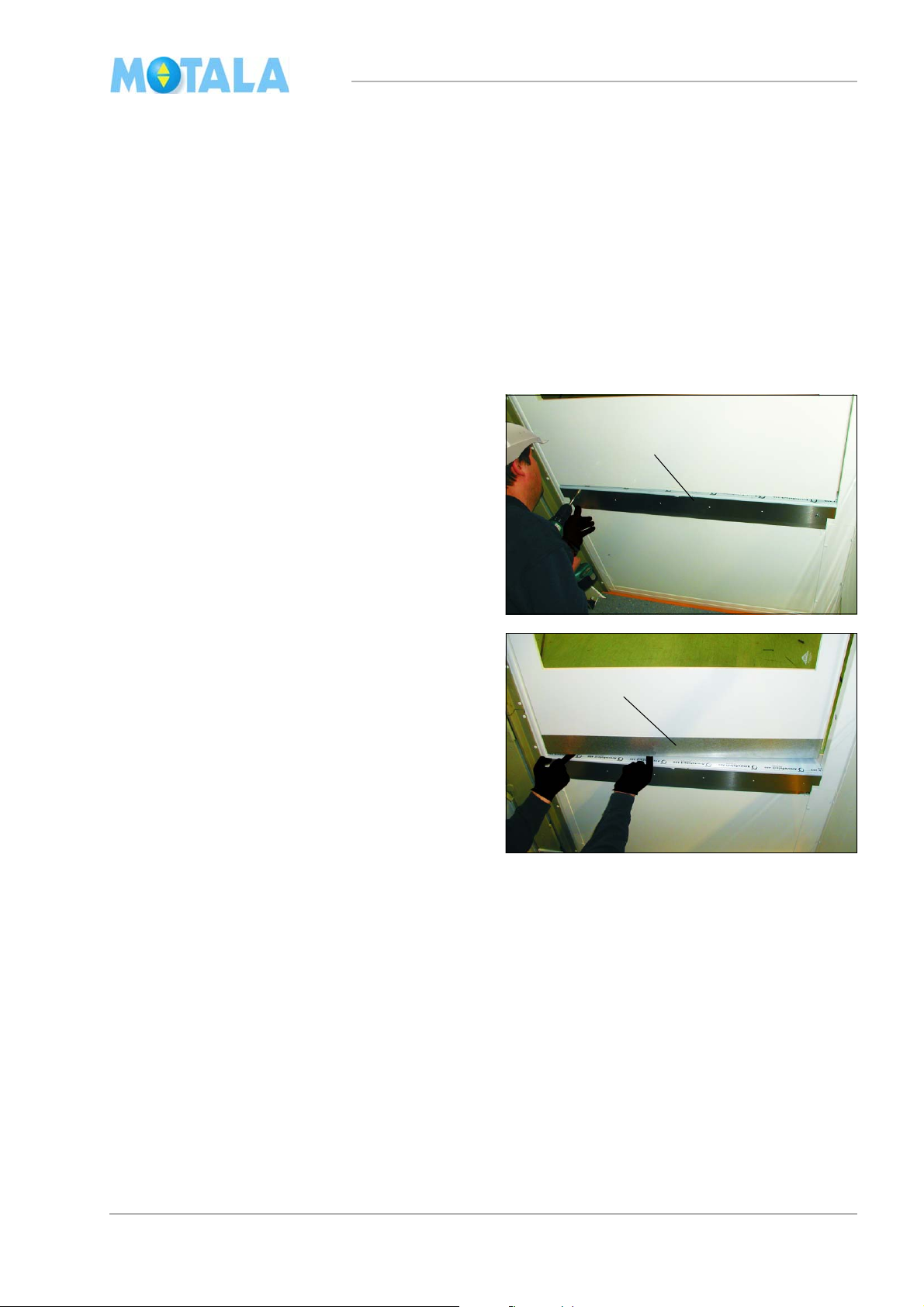
Fixing plates
1. Secure the fixing plates (90x50x2000 mm)
for the “large cover plates” of the guide rails
with screws. The fixing plates must be
edge to edge with the flange of the corner
profiles. Start from the bottom, 50 mm from
the pit. Note! You now have to loose the
62:N switch and re-install it up on the fixing
plate.
2. Make notches for cables and wires, if any.
Applies to two-entrance lifts and open ad-
(
jacent lifts.)
3. The fixing plates must end where the top
urning cases of the guide rails begin.
t
Check that the safety gear can rotate
freely.
36
MC2000 – Assembly Instruction Manual
1
2
3
4
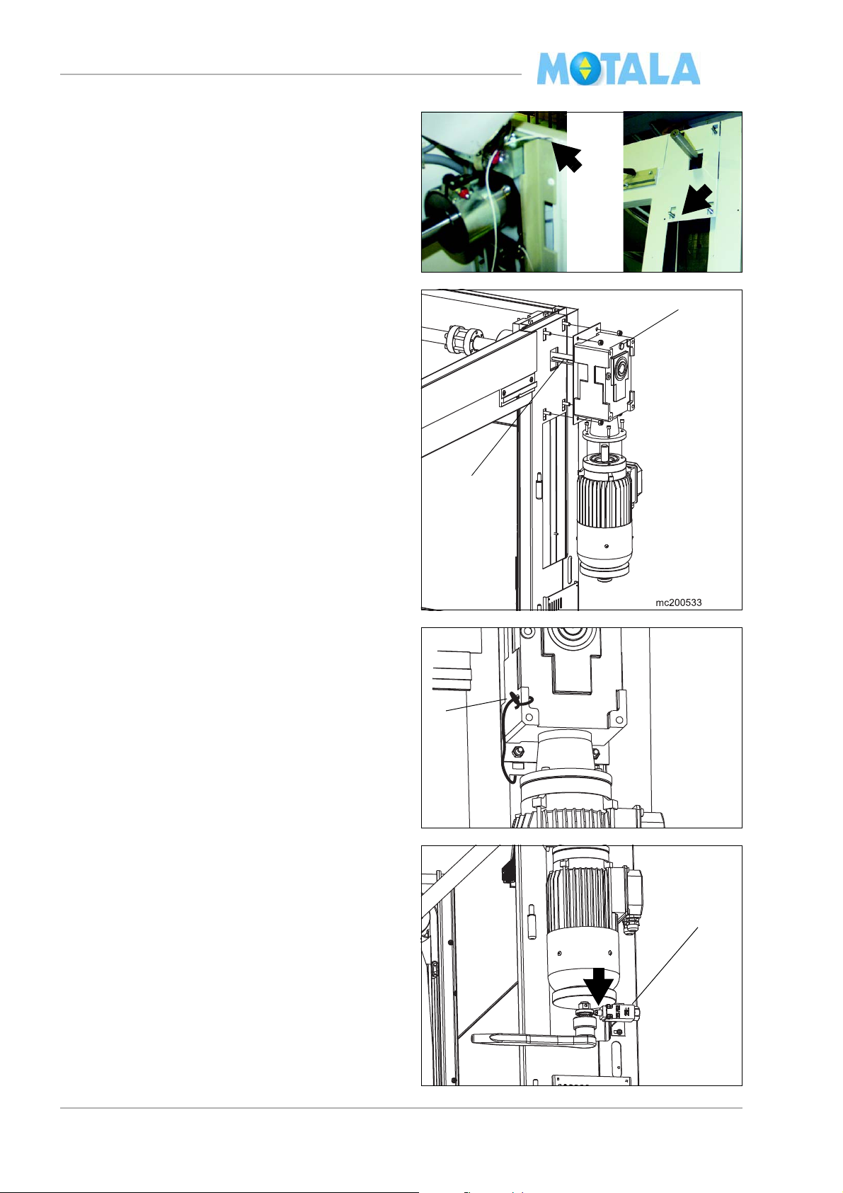
Travelling flex cable, panel plate, overload unit and control panel
1. Run the lift to the topmost landing.
2. Lower the flex cable (1) with the platform
rminals in the end on the opposite side of
te
the door on floor 0. The unpeeled part of
the cable should reach the pit precisely.
Lower the cable another 1150 mm.
3. Secure the travelling cable with U-fasten-
ers (2).
4. Fasten the remaining parts of the travelling
e with U-fasteners. The cable must not
cabl
run down further than 180 mm from the
well top. Check that no cables can touch
the driving shaft. Note! If the lift has an
electrical emergency lowering device (3).
Also leave place for that.
5. Install the protection over the safety gear
).
(4
6. Fit (if any) the electrical emergency lower-
ing device. Route the cables 28 and 29 to
e control panel.
th
7. Switch off the supply voltage of the lift,
ute and connect the travelling cable to
ro
block X1 in the control panel.
8. Switch on the supply voltage of the lift,
ive down to landing 0 and switch off the
dr
power.
9. Fit the retiring ramp on the same side as
e motor is fitted. A-side.
th
10. Attach the panel shelf with electric equip-
ment on the panel plate of the platform.
37
MC2000 – Assembly Instruction Manual
10
11
13
12
15
11. Place the panel plate on the platform.
12. Thread the travelling cable through the
e “nearest the side as the cable hangs
hol
on” in the panel plate and secure the cable
with U-fasteners. Note! Check that the
screws are not placed under the panel
shelf or damage the shelf components.
13. Thread the cable from the floor sensitive
contacts trough the hole. Stretch it
edge
and lock it with cable tie.
14. Fasten the two angle brackets for the panel
lf with hexagon-headed screws, M6x10,
she
and plain washers in each slide.
15. Fasten the angle brackets in the panel
ate with self tapping screws. Adjust the
pl
position of the brackets with the screws so
that the panel plate is in an exact central
position between the slides.
16. Adjust the distance between the sensetive
list of the panel plate and the lift well
edge
wall. The distance should be 10-15 mm,
maximally 15 mm. Adjust the distance by
loosening the hexagon-headed screws.
17. Fasten the fixing with contacts 66:,61: (if
) and 51: in the upper pre-drilled holes
any
in the slide on the opposite side of the side
where the motor is placed.
38
MC2000 – Assembly Instruction Manual
1
2
3
4
5
Overload unit
Bring the platform to the middle of the door
ng so you can reach to fit the overload
openi
arm (1) from underneath.
Fit with screws in the pre-drilled holes nearest
nner corner (2).
the i
Adjust the distance between arm and panel
te to be15mm at the end of the arm (3) when
pla
the platform is unloaded.
Fasten the arm in the holes that remain. Use
f-drilling screws.
sel
Fit the overload flag (4) from inside of the panel.
Pre-adjust the transmitter (5) to a gap of 2mm
between
transmitter and the flag and at the
same time the distance between the edge of
the flag to centre of the transmitter to about
6mm.
Note. Do not
tighten the nuts to hard you may
damaged the transmitter.
Adjustment with load has to be made later.
39

MC2000 – Assembly Instruction Manual
Electric connections on the platform panel
plate
All electric connections are made according to
e electrical diagram of the lift. Fasten all ca-
th
bles from the slide to the panel shelf on the inside of the angle bracket with cable tie (not on
e top or bottom sides).
th
1. Connect the following cables:
• the travelling cable 51.
• the cable from the floor sensitve edge contacts 57.
• the cable from the sensitive edge of the
anel plate 56.
p
• the cables 62-65 from the high speed contact 66:, 59:, 51: and intermediate floor
ector 61:, if any.
det
• the cable 53 from the retiring ramp.
2. Connect alarm and telephone equipment, if
. Do not yet install the battery, as the
any
alarm signal might ring.
3. Push in both the stopbutton on the control
anel and the commission box.
p
4. Connect the control panel.
5. Connect the battery. Im
portant! If the lift
has the electrical emergency lowering
system as an option. The battery on the
panel is replaced with the battery in the
emergency lowering unit, suited at the
top of the shaft. You shall not in any circumstances connect two batteries!
6. Switch on the main power
7. Bring in test load on the platform.
8. Adjust by move the transmitter in or outwards. The transmitter shall light when it’s
ivated. Also check that input 0 on the
act
PLC lights up. Note. Do not tighten the
nuts to hard you may damaged the transmitter.
40

MC2000 – Assembly Instruction Manual
1
mc200542
1
mc200543
2
3
4
9. Fasten the platform panel with four screws
(1). Place the cables so that they cannot be
damaged.
Cancelling drive command box
1. Push the stop button on platform panel.
Warning! In this position, the button is connected in parallel with the emergency stop
the drive command box.
of
2. Disconnect the command box from the
rol panel.
cont
3. Reset the stop button on the platform
nel.
pa
Ceiling
The ceiling should be placed at a height of 2100
m
m above the floor of the topmost landing.
1. Fasten three L-shaped mouldings on all
ls except the wall of the drive side. Turn
wal
the side with the pre-drilled screw holes upwards.
2. Install the ceiling (4). The electric fittings (2)
d be centred in the lift well.
shoul
3. Route and the light cable 18 to the control
anel. Secure the cable on the safety gear
p
cover plate to prevent it from getting dammiged.
arning! There is power on the terminal
4. W
LJ for the light even if the main switch is
set to OFF! Connect if the power is com-
pletely OFF from the main central and also
e F8 fused shall be removed in the con-
th
trol panel.
41

MC2000 – Assembly Instruction Manual 2011-10
5
3
4
5. Important! Fasten the ceiling in the L-
shaped moulding with screws from underneath (5).
Commencing from platform control panel
1. Switch the main switch 220: to ON. Note!
The lift is equipped with PLC control so it
will run down to landing 0 in order to reset
the PLC program, no matter which button
you push.
2. Run to the upper terminal floor, to exactly
correct height.
3. Install the terminal floor stop switch so that
the roller of the arm is in close contact with
the slide. Check that the arm cannot get
stuck against the edge of the guide rail.
Fasten the cable.
4. If the lift has more than two landings, run it
down and install intermediate floor magnets. Switch the supply voltage off and on
and run to landing 0 in order to reset the lift.
• Note! The size of the magnet is15X30 mm
and must be fitted vertical. (Changed from
horizontal to vertical in okt 201 1 from control
panel No 6000 and higher)
42

MC2000 – Assembly Instruction Manual 2011-10
1
1
Lock arms
5. Run the lift to an exact position on each
floor and fit the lock arm. When the lift is on
a certain floor, the roller of the lock arm
should be in the centre of the ramp. Note!
There is an exception for the bottom and
top floors: there, the lock arm should be fitted so that, when the lift reaches the floor,
the roller has just reached the flat part of
the ramp.
6. Adjust the length of the lock wires by cutting the outer cover so that it reaches the
lock arm. Let the inner cover run a short
distance through the lock arm sleeve. Pull it
down and fasten excessive wire in the recess of the arm.
Highspeed contact and magnet
1. Adjust the distance of the floor counting
contact 61: (if any) and highspeed contact
to 7 mm from the lift well wall.
2. Fasten the highspeed contact magnet (1)
at every floor. Adjust the magnet so it
starts and ends 50 mm from the floor in
question.
43

MC2000 – Assembly Instruction Manual
2
3. Fit the final stop ramp (2) for the 51: contact at the top and ground floor. The switch
uld be effected by the ramp if the lift
sho
runs more than 15mm above the top floor
and 15mm below the ground floor. The
ramp shall align against the angle plate
corner.
Lubrication
1. Lubricate the C-profile guide rails. Use Superlube synthetic grease, article item
number
100401.
2. Lubricate the roller of the lock arms where
t
he wire runs.
44

MC2000 – Assembly Instruction Manual
1
2
1
Cover plates
Check before fitting cover plates
Check
• that the lift stops at the landings
+ - 10 mm.
• that the locks open properly, even if you pull
the door
• that the safety gear is placed correctly in relation to the motor position, see illustration,
and t
works.
• Check safety according to document IQ-
K98_10_C
B
Small cover plates
and call the lift simultaneously.
hat the safetygear testing function
1. Fasten the small guide rail cover plates
with pop rivets. Start from the bottom and
work upwards in the lift well. Note! Take
care not to fasten pop rivets in the locks
and cables that might be placed behind the
covers.
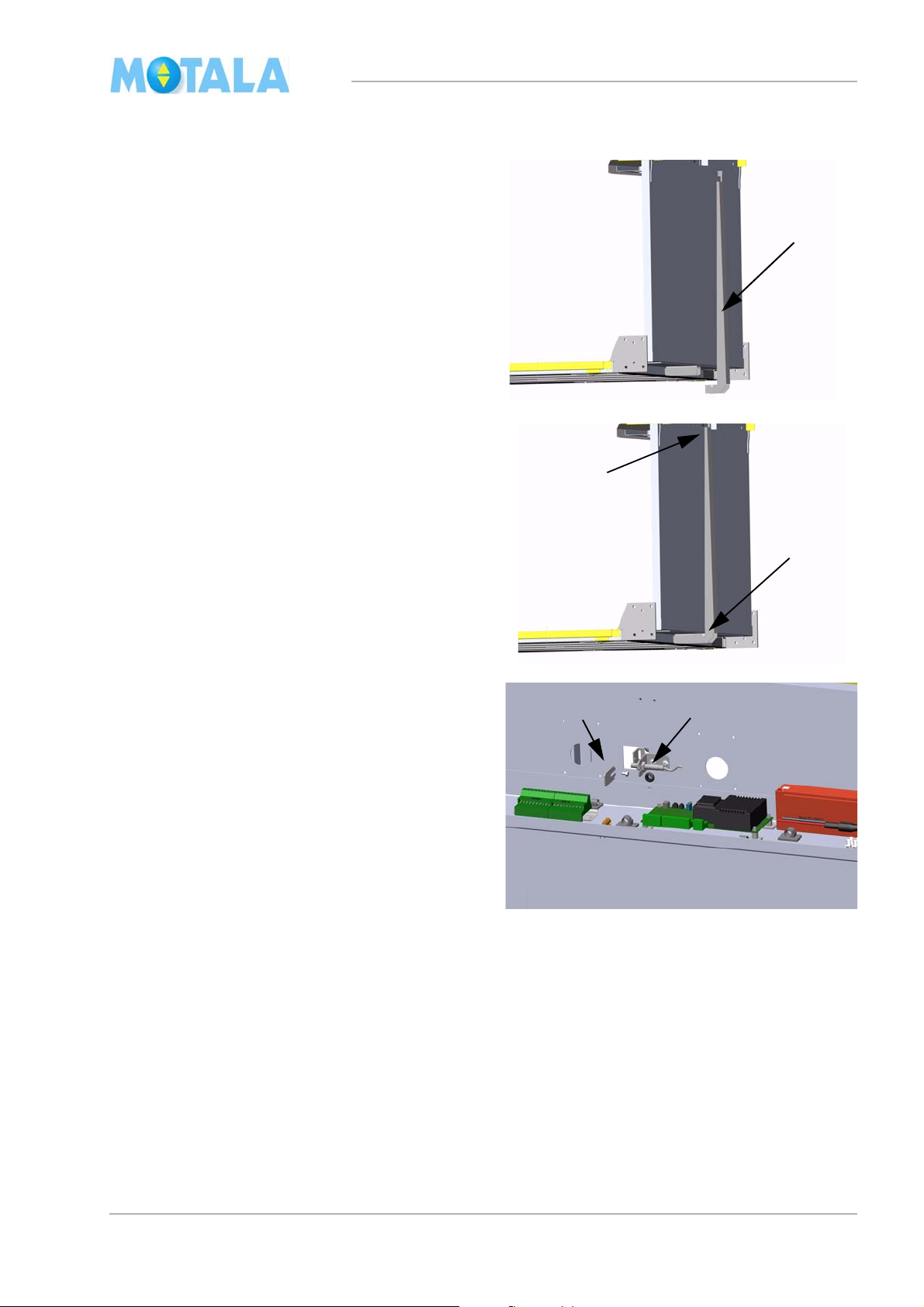
Shaft hood
1. Fit the drive shaft cover plate (1). The illus-
tration shows a lift with 2200 mm ceiling
ght.
hei
2. Lose the screws for the ceiling a little, so
you can push th
shaft cover plate (2).
3. Then tighten the screws to the ceiling
n.
agai
e ceiling tight against the
45

MC2000 – Assembly Instruction Manual
2
4
3
On lifts with 1300 mm ceiling height the drive
shaf
t cover plate is fastened in the same way
and is also fastened with screws from the top
side.
Large cover plates
1. Start from the bottom with the lowest cover
plates (they can usually be shorter than the
others) 50mm up from the pit.
2. Fit the next cover plates.
3. Continue with the remaining cover plates
hat measure 2000 mm. The two upper-
t
most cover plates (2) must reach about
10 mm above the edge of the drive shaft
er plate.
cov
4. Check that the safety gear can rotate
reely.
f
Cover plate, platform
5. Run the lift to the bottom position.
6. Fit the cover plates (3) with two short
rews (4). Note! Maximum length 8 mm.
sc
er screws might scratch the large
Long
cover plates of the guide rail while the lift is
running.
46
MC2000 – Assembly Instruction Manual
Finishing work
1. Fit the motor and the electric cabinet top
cover.
2. Put up all necessary signs, taking local demands into consideration.
3. Clean the lift.
4. If necessary, patch damaged paint.
5. Inform customers and working staff about
e lift and its functions.
th
Final inspection and own inspection
Make a final inspection and, at the same time,
fill in the inspection form.
47
MC2000 – Assembly Instruction Manual
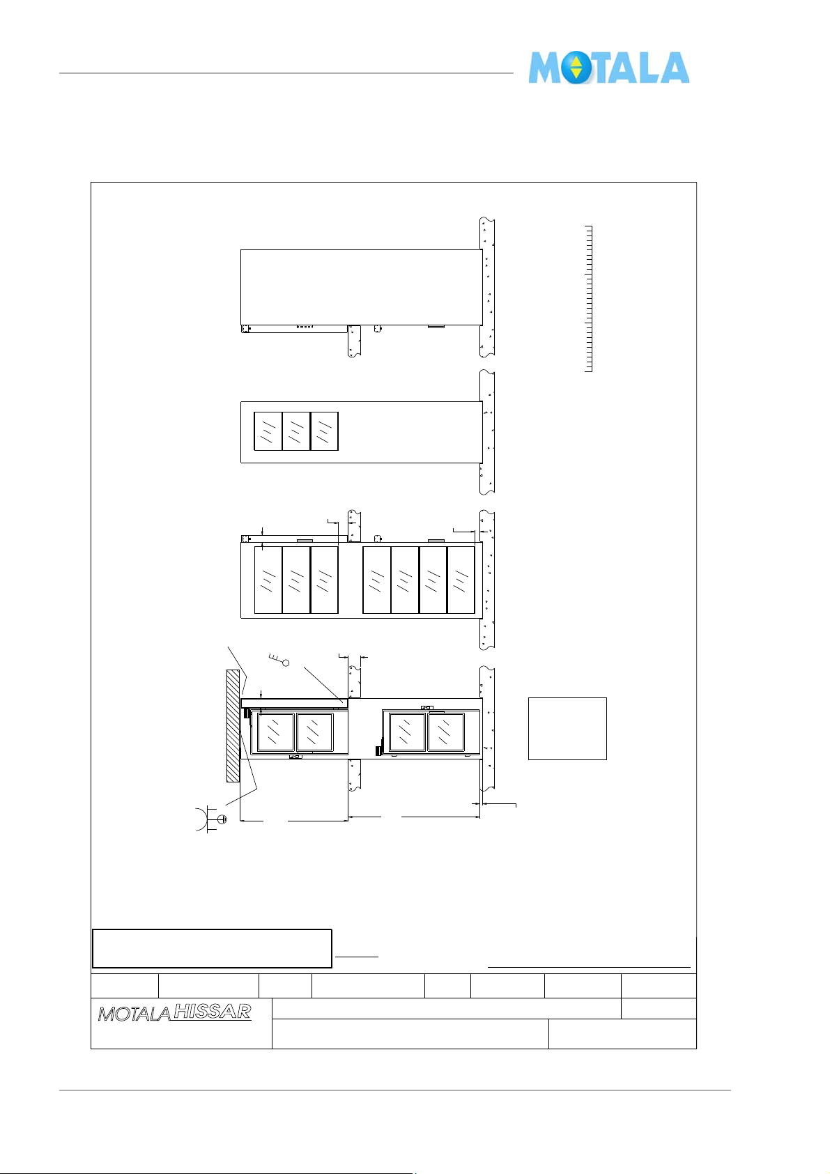
145
Pit depth
60 +5/-0
and painted
Replaces
Drawing/Lift number
Motala Lift MC2000
Object
Lift type
Note! Basic free construction heights.
Floor with automatic doors requires free height min. 2200 mm.
Floor without automatic doors requires free height min. 2150 mm.
Delivery time
Box 4029 591 04 MOT ALA
Tel +46 141 237050 Fax +46 141 237051
Drawn
RMS Produktion
Demo Mo tala Hissar
Check .ApprovedSeller Scale -Not according to scale
APPROVED with registered changes:
Purchaser’s signature:
A
A
030116
9187
Replaced by
Dat.
Scale
0 1
3m2
FF ±0
FF ±0
HIT
HISS
1590
From above
Joist hole
Width 1280
FF ±0
FF ±0
A
B
C
D
30 mm.
HIT
HISS
L1
N
1d
1d
1
Ceiling height
2200
210
FF +2700
+0/-5 mm
100
200
250
400V/10A
A
B
D
C
IMPORTANT! Please check and adjust measures, door hangers etc.
Please return the layout drawing immediately.
Floor 0
Freely plumbed
Should be horizontal
Floor
Fitting space
Depth
Layout drawing
48
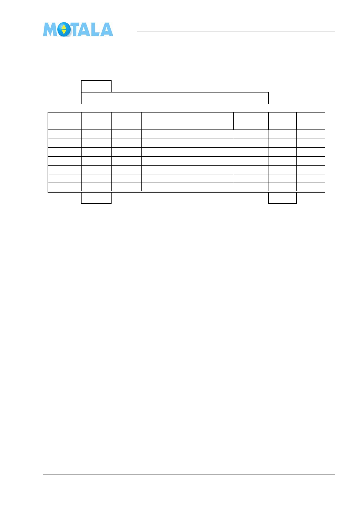
Checklist
Lift number: 9187
Project: MC2/2 Dem o Motal a His s ar
L ength
[mm]
Door
Al-prof.
Length
[mm]
Door
Al-prof.
1 2155 Door 1 2950 Al-prof.
2 535 Al-prof. 2 2010 Al-prof.
3 2270 Door 3
4 4
5 5
6 6
7 7
4960 mm Total height 4960 mm
Side A
Side C
From below
Cable hole
From below
MC2000 – Assembly Instruction Manual
49

MC2000 – Assembly Instruction Manual
Approvals and version history
Table 1:
Issue Date Description of change Ref CR Approve by
Rev.A 2005-05-04
1.01 2007-01-31 Change of version counting. See first page
Adding this side. See “Approvals and version history”
on page 50.
Headline and text modified in step 2 and 10. See
“Travelling flex cable, panel plate, overload unit and
control panel” on page 37.
New steps added for overload unit. See “Overload
unit” on page 39.
Step 3, 6, 7 and 8 added. See “Electric connections
on the platform panel plate” on page 40.
50

MC2000 – Assembly Instruction Manual
Attachments
51
MOTALA HISSAR AB
Hidden hinges
Mounting and adjustment of door with hidden
hinges
2012-04-12
Draft 2 – Method for mounting door with hidden hinges.
Mounting door leaf
Tips!
Hold the door leaf in about 45 degree
opening angle so that the door part of
the hinge rests against the edge of the
frame as shown, this makes it easier to
steer hinges on the pins that are
hidden inside the frame.
Door stop
Install the door stop (1) so that the door
is not possible to open more than 90
degrees.
Note!
If the door is opened more than 90
degrees there is a risk to damage
hinge or door frame (2).
Adjusting the hinges
The hinges can only be adjusted in
height.
1. Adjust the door in height by
turning the Allen screw.
2. Lock Allen screw with hex.
Note! Adjust the upper and
lower hinge equal. The hinges
can only be adjusted in height.
Important!
Both the upper and lower hinge must be adjusted so
that the ball of the hinge rests in the cup in order to
avoid play in the hinges.
Install the cover at both hinges.
Insert the controller that fits into the
groove of the door frame and snap on
lid.
Done
Removing the cover
Press gently with a screwdriver on the
side as shown until the lid comes off.

MOTALA MC2000 – Mechanical blocking device
Instruction
Mechanical blocking device in the pit MC2000
Rev. B
© 2012 Motalahissar AB 0 (12) IQ56-03 Rev: B

MOTALA MC2000 – Mechanical blocking device
Instruction
All rights reserved.
No part of the contents of this document may be copied, reproduced or transmitted in any form or by
any means, or translated into another language or format, in whole or part, without prior written
permission of MOTALA HISSAR Corporation.
CONTACT:
MOTALA HISSAR AB
Luxorgatan 1
BOX 4029
591 04 MOTALA
+46 141 23 70 50
www.motalahissar.se
© 2012 Motalahissar AB 1 (12) IQ56-03 Rev: B

MOTALA MC2000 – Mechanical blocking device
Instruction
TABLE OF CONTENTS
1. GENERAL .................................................................................................................3
RELATED DOCUMENTS ..................................................................................................3
2. SAFETY .....................................................................................................................3
3. FASTENERS USED IN THE INSTALLATION INSTRUCTION ................................3
4. OVERVIEW................................................................................................................4
MECHANICAL BLOCKING DEVICE ....................................................................................4
THE OPERATING HANDLE TO THE MECHANICAL BLOCKING DEVICE ....................................4
5. INSTALLATION ........................................................................................................5
MOUNT THE FIRST BRACKET..........................................................................................5
MOUNT THE COVER PLATE BRACKET ..............................................................................5
MOUNT THE SECOND BRACKET .....................................................................................6
MOUNT THE FIRST PULLEY ............................................................................................6
MOUNT THE SECOND PULLEY ........................................................................................7
EXAMPLE OF PULLEY PLACEMENT ..................................................................................7
MOUNT THE OPERATING HANDLE AND THE WARNING SIGN...............................................8
MOUNT THE WIRE .........................................................................................................8
MOUNT THE PLATFORM FRAME ......................................................................................9
MOUNT THE MECHANICAL BLOCKING DEVICE ..................................................................9
ADJUSTMENT OF THE WIRE ........................................................................................ 10
REMOVE SLACK IN THE OPERATING HANDLE AND WIRE. ................................................ 10
MOUNT THE RETIRING RAMP AND LIMIT SWITCH CAMS .................................................. 11
MOUNT THE LIMIT SWITCHES ...................................................................................... 11
ADJUSTMENT OF THE LIMIT SWITCHES POSITIONS ........................................................ 12
6. APPROVALS AND VERSION HISTORY .............................................................. 12
© 2012 Motalahissar AB 2 (12) IQ56-03 Rev: B

MOTALA MC2000 – Mechanical blocking device
Number
Description
view
100223
Staps 4,2x14 CS Ph2
100197
RXS B8x16
102040
MC6S M4x8
100179
M6S M10x16
100136
MC6S M6x10
Instruction
1. GENERAL
This mechanical blocking device are special designed to be fitted on MC2000. Follow this
instruction carefully to ensure an efficient and trouble-free installation.
Related documents
This instruction is to be used with the MC2000 installation instruction.
2. SAFETY
Personal safety precautions for fitters.
Always use Personal Protective Equipment (PPE). Always use Head protection, Eye
protection, Foot protection, Hand protection, Protective clothing, Face shield and
Safety harness.
Follow the safety precautions in the MC2000 installation instruction.
3. Fasteners used in the installation instruction
© 2012 Motalahissar AB 3 (12) IQ56-03 Rev: B

MOTALA MC2000 – Mechanical blocking device
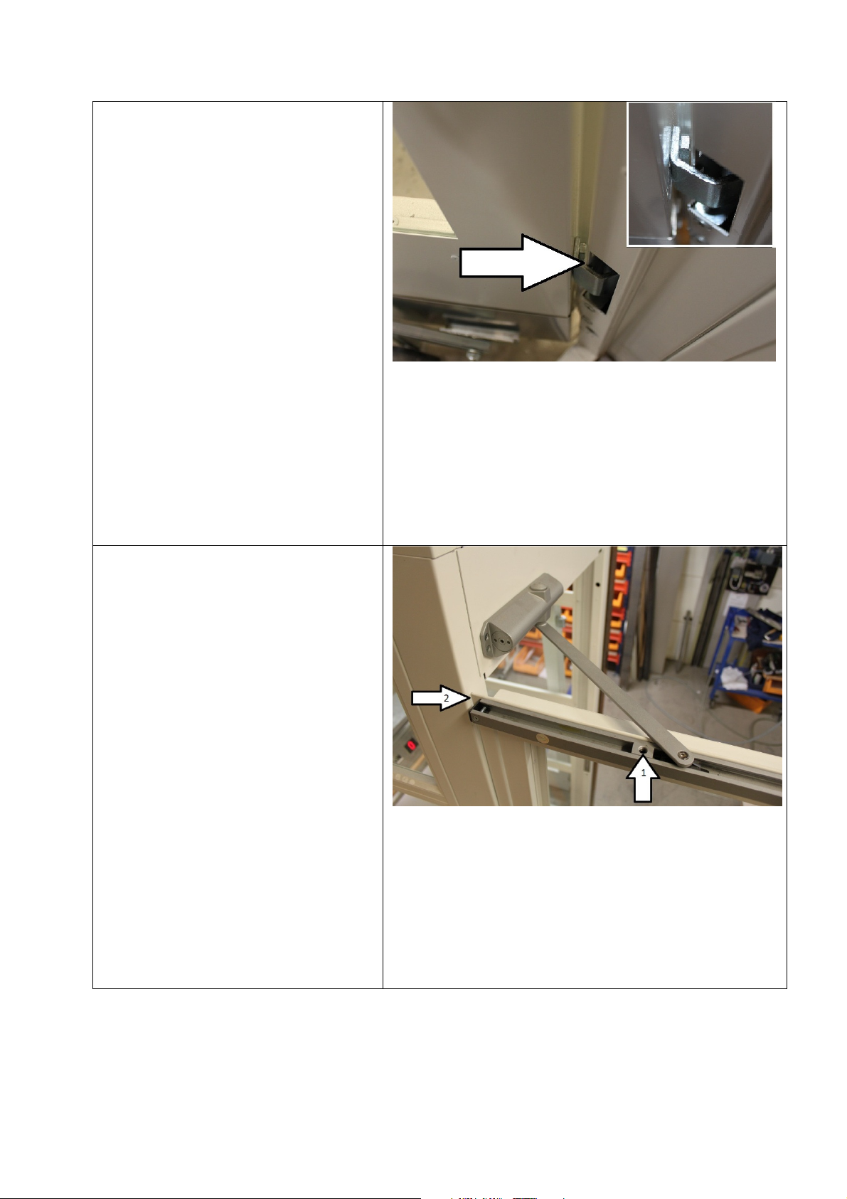
Mechanical blocking device
1. The mechanical blocking
device in the pit is always
placed on the opposite side
from the motor and the retiring
ramp. It is used to provide a
safety space of 500 mm when
working in the pit.
The operating handle to the
mechanical blocking
device
1. Open the bottom floor door,
the operating handle is placed
in the pit just inside the door.
2. Lift up (2.1) and swing out
(2.2) the arm to activate the
mechanical blocking device.
3. The green light on the
emergency stop device must
be switched on before entering
the pit.
4. When entered the pit push the
emergency stop device.
5. When you are leaving the pit
make the steps in reverse
order.
Instruction
4. Overview
© 2012 Motalahissar AB 4 (12) IQ56-03 Rev: B

MOTALA MC2000 – Mechanical blocking device
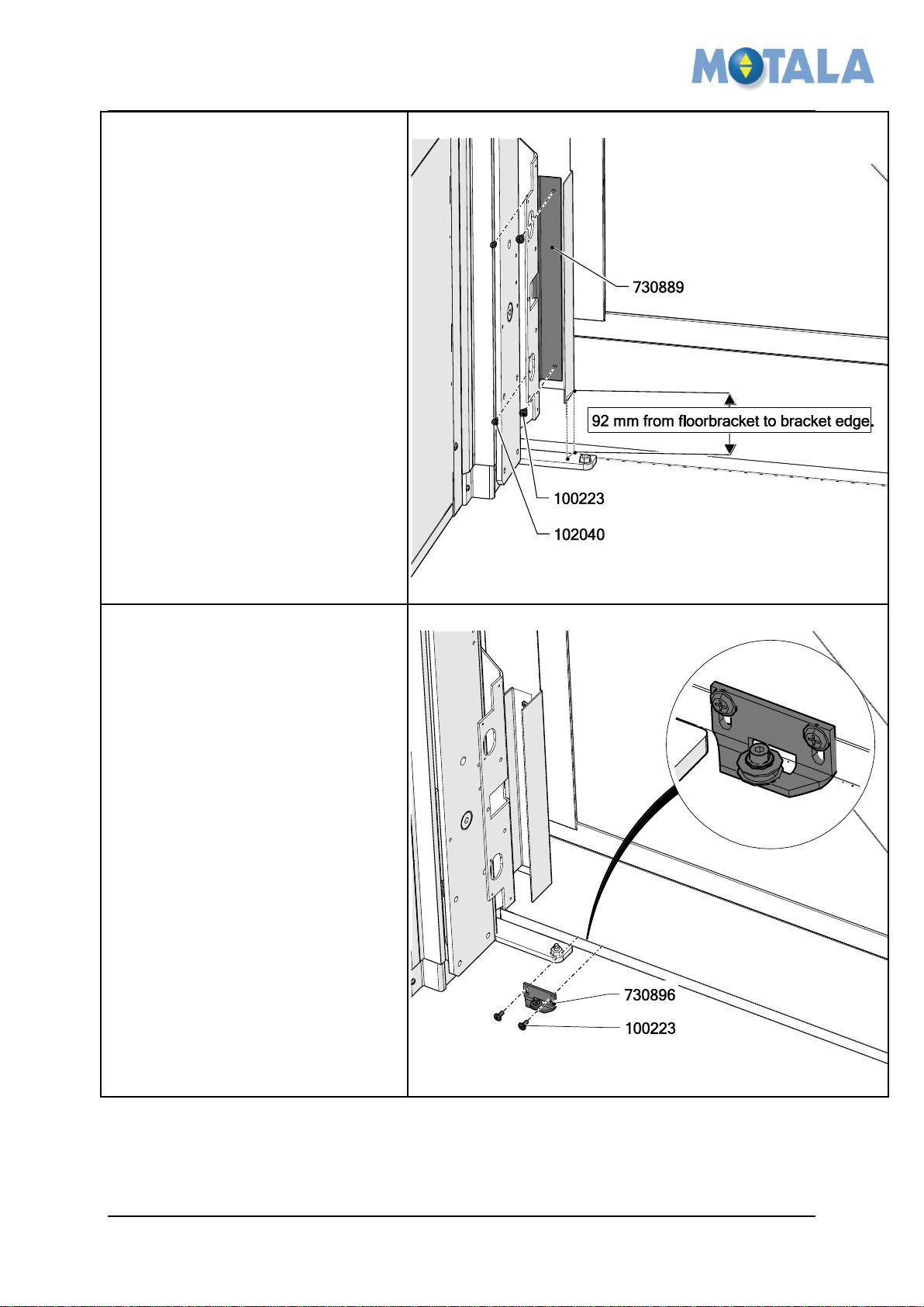
Mount the first bracket
1. Mount the bracket 730888 in
the pre-drilled holes in the
guide, use 4x 100197.
Mount the cover plate bracket
1. Mount the cover plate 730624,
use 8x 100223.
2. Make sure that the cover plate
edge rest against the edge of
the door frame (or aluminum)
profile. And its lower end is
100 mm over the pit floor.
Instruction
5. Installation
© 2012 Motalahissar AB 5 (12) IQ56-03 Rev: B
MOTALA MC2000 – Mechanical blocking device
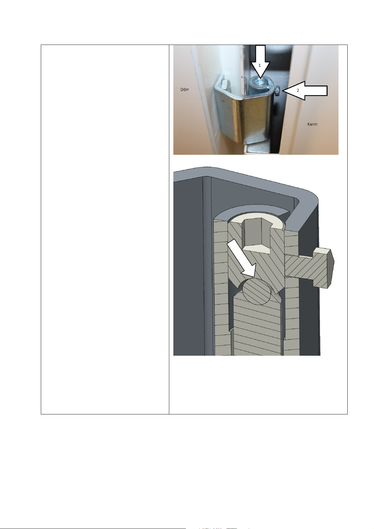
Mount the second bracket
1. Put the second bracket
730889 behind the first
bracket.
2. Use 2x 102040.
3. Use 2x 100223.
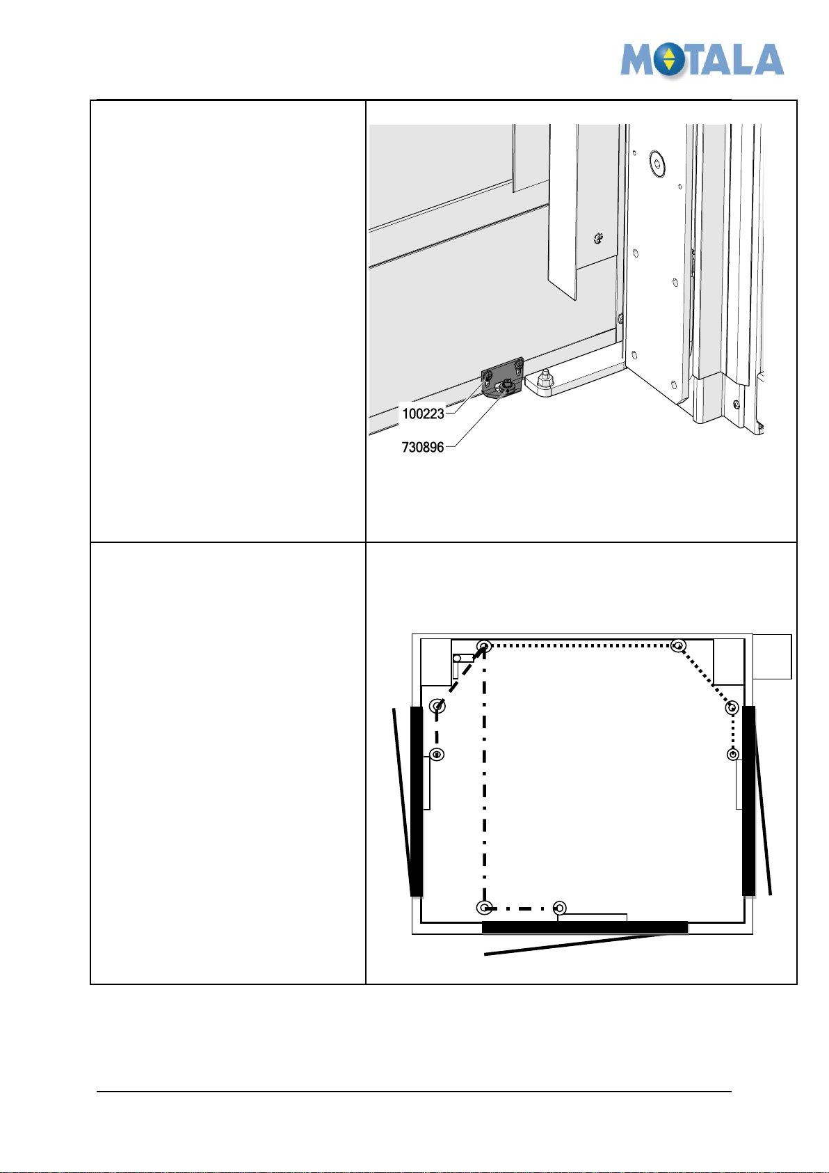
Mount the first pulley
1. The first pulley 730896 is
mounted right next to the floor
bracket.
2. Use 2x 100223
Instruction
© 2012 Motalahissar AB 6 (12) IQ56-03 Rev: B
MOTALA MC2000 – Mechanical blocking device
Mount the second pulley
1. The second pulley 730896 is
mounted right next to the floor
bracket.
2. Use 2x 100223.
3. Note that the second pulley
can be placed in a variety of
places depending on the
placement of the mechanical
blocking device and the door
giving access to the pit. See
example below.
Example of pulley placement
1. If the mechanical blocking
device is placed to the left this
is 3 alternative for the pulleys
and the wire. See the picture
for alternative door
placements 1, 2 and 3.
2. If the mechanical blocking
device is place to the right the
alternatives will be mirrored.
1.
2.
3.
Instruction
© 2012 Motalahissar AB 7 (12) IQ56-03 Rev: B

MOTALA MC2000 – Mechanical blocking device
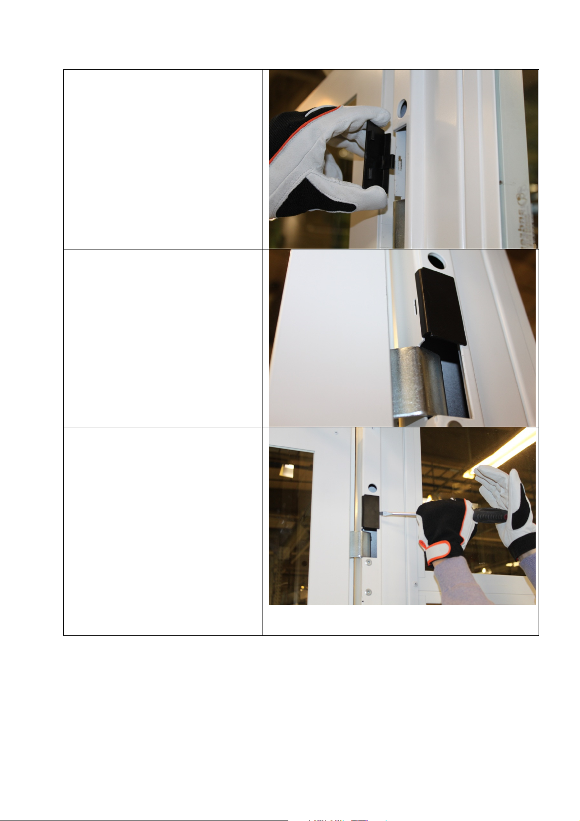
Mount the operating handle and
the warning sign
1. Place the operating handle
731032 inside of the threshold
on the door giving access to
the pit, use 2x 100223.
2. Place the warning sign on the
floor at the bottom of the pit,
fix it with glue or screws.
Mount the wire
1. Pull the wire from the
mechanical blocking device to
the operating handle.
2. The wire end must not stick
out from the wire lock at the
handle, that would prevent the
handle movement.
Instruction
© 2012 Motalahissar AB 8 (12) IQ56-03 Rev: B
MOTALA MC2000 – Mechanical blocking device
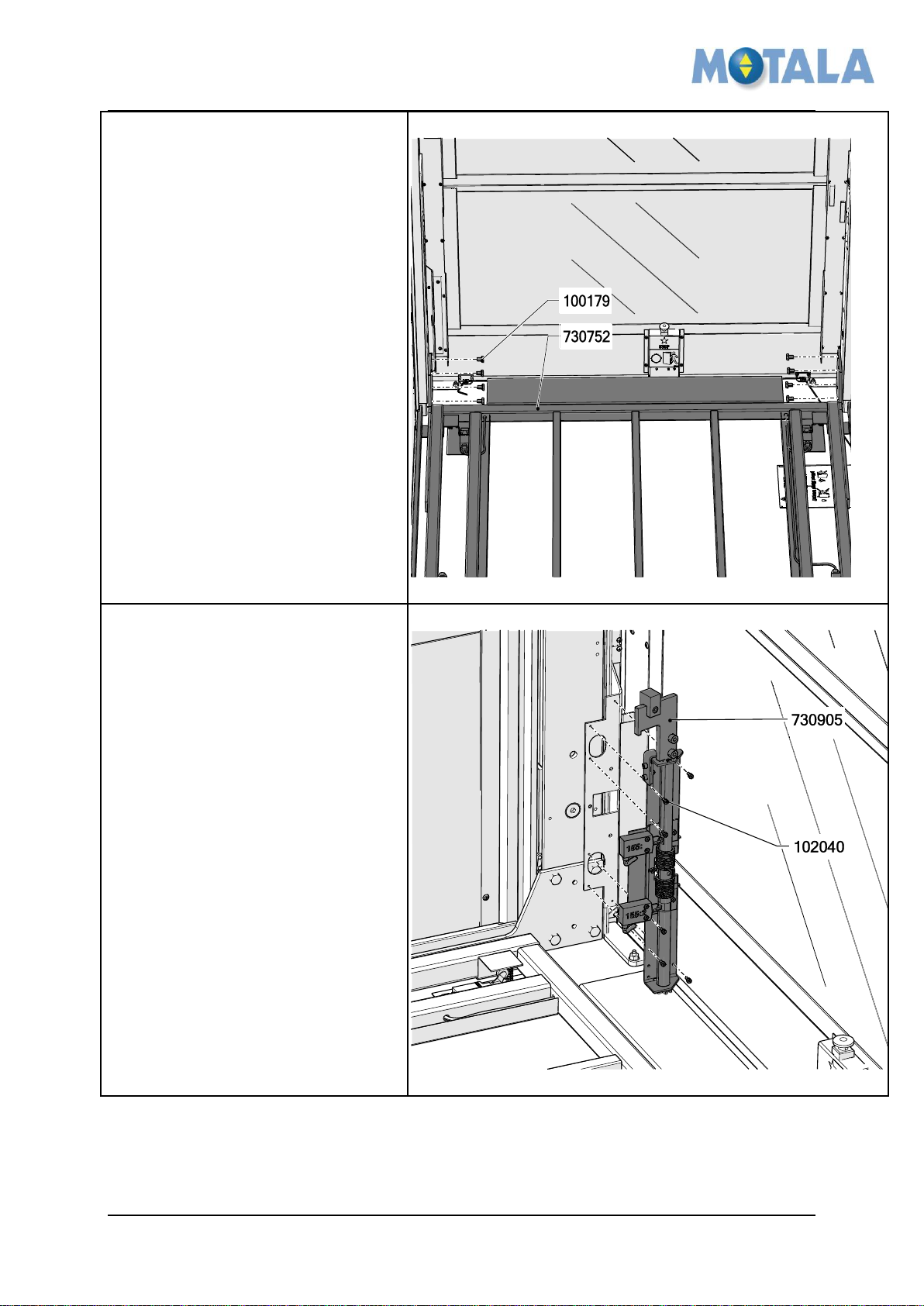
Mount the platform frame
1. Mount the platform frame
730752, use 8x 100179.
2. See the MC2000 installation
instruction for further important
details on mounting the
platform.
Mount the mechanical blocking
device
1. Mount the mechanical
blocking device 730905, use
6x 102040.
Instruction
© 2012 Motalahissar AB 9 (12) IQ56-03 Rev: B
MOTALA MC2000 – Mechanical blocking device
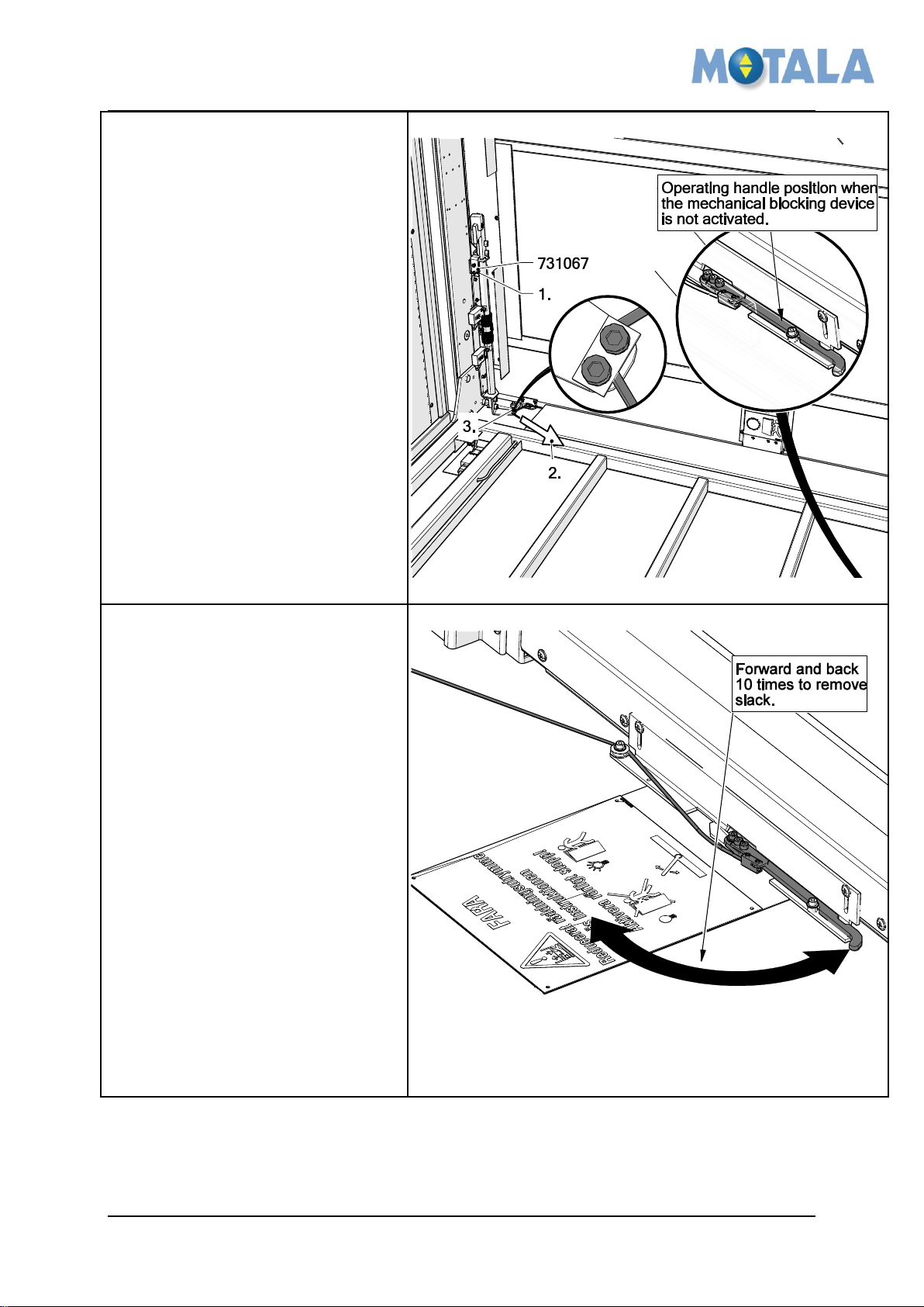
Adjustment of the wire
1. Make sure the red device
731067 is in its position. And
the operating handle is in its
inactivated position.
2. Stretch the wire.
3. Tighten the two screws to lock
the wire.
4. Remove the red device
731067 and check that the
mechanical blocking device is
still in its inactivated position.
5. Test that the wire, stop and
handle function works
properly. (See - 4. Overview)
Remove slack in the operating
handle and wire.
1. To make the mechanical stop
work properly over time the
slack in the operating handle
and the wire must be
eliminated.
2. Turn the handle forward and
back 10 times.
3. Test that the wire, stop and
handle function works
properly. (See - 4. Overview),
if not repeat (adjustment of the
wire 1-5)
Instruction
© 2012 Motalahissar AB 10 (12) IQ56-03 Rev: B
MOTALA MC2000 – Mechanical blocking device
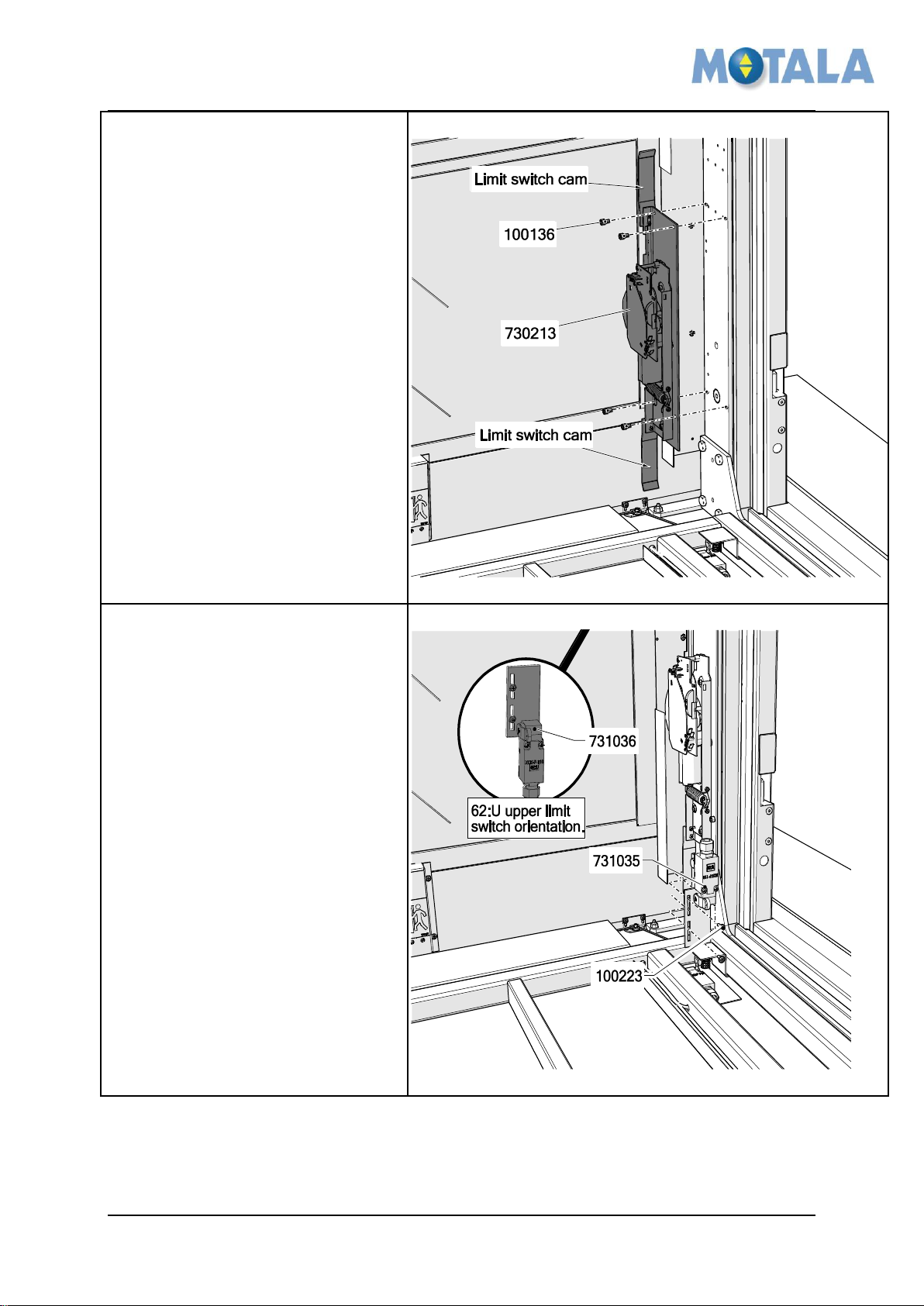
Mount the retiring ramp and
limit switch cams
1. Mount the retiring ramp
730213, use 4x 100136.
Mount the limit switches
1. Mount the retiring ramp
731035 (62:N) and 731036
(62:U), use 4x 100223.
Instruction
© 2012 Motalahissar AB 11 (12) IQ56-03 Rev: B
MOTALA MC2000 – Mechanical blocking device
Adjustment of the limit switches
positions
1. Place the lower switch so that
the ridge affects the switch 25
mm before the platform
reaches the lower floor level.
2. Place the upper switch so that
the cam break the switch just
when the platform reaches the
upper floor level.
Rev
Date
Description of change
Ref CR
Checked by
Approved by
-
2012-09-05
Draft 1.0
10521
Niklas Adell
Ari Nieminen
A
2012-09-25
New transport safety device
12629
Niklas Adell
Ari Nieminen
B
2013-02-19
Remove slack in the operating handle and
wire
13536
Niklas Adell
Ari Nieminen
C
Instruction
6. APPROVALS AND VERSION HISTORY
Compiled by: Designer/Ronnie Sundström
© 2012 Motalahissar AB 12 (12) IQ56-03 Rev: B
MOTALA MC2000 – Updated version of the platform wall
Instruction
Updated version of the platform wall MC2000
Rev. B
© 2012 Motalahissar AB 0 (14) IQ56-04 Rev: B

MOTALA MC2000 – Updated version of the platform wall
Instruction
All rights reserved.
No part of the contents of this document may be copied, reproduced or transmitted in any form or by
any means, or translated into another language or format, in whole or part, without prior written
permission of MOTALA HISSAR Corporation.
CONTACT:
MOTALA HISSAR AB
Luxorgatan 1
BOX 4029
591 04 MOTALA
+46 141 23 70 50
www.motalahissar.se
© 2012 Motalahissar AB 1 (14) IQ56-04 Rev: B

MOTALA MC2000 – Updated version of the platform wall
Instruction
TABLE OF CONTENTS
1. GENERAL .................................................................................................................3
RELATED DOCUMENTS ..................................................................................................3
2. SAFETY .....................................................................................................................3
3. FASTENERS USED IN THE INSTALLATION INSTRUCTION ................................3
4. INSTALLATION ........................................................................................................4
INSTALL THE OVERLOAD ARM ........................................................................................4
INSTALL THE PLATFORM WALL .......................................................................................4
ATTACH THE TRAVELING CABLE .....................................................................................5
SENSITIVE EDGE CABLE ................................................................................................5
FIT THE SHELF..............................................................................................................6
FIT THE ANGLE BRACKETS .............................................................................................6
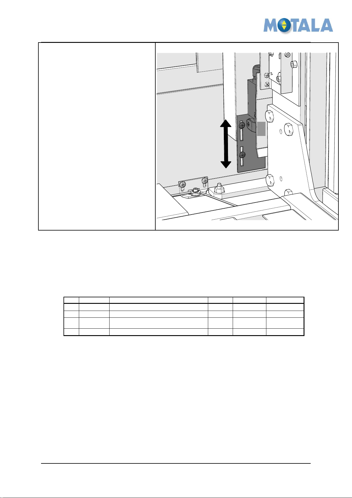
INSTALL THE SWITCH UNIT FOR THE UPPER SENSITIVE EDGE ...........................................7
FIT THE SWITCH FOR THE OVER LOAD DEVICE .................................................................7
FIX THE OVERLOAD ARM ...............................................................................................8
FIT THE EARTH TERMINAL AND CIRCUITS BOARD .............................................................8
FIT THE UPPER SENSITIVE EDGE ....................................................................................9
PLACE THE SIDE PANELS ...............................................................................................9
FIX THE SIDE PANELS ................................................................................................. 10
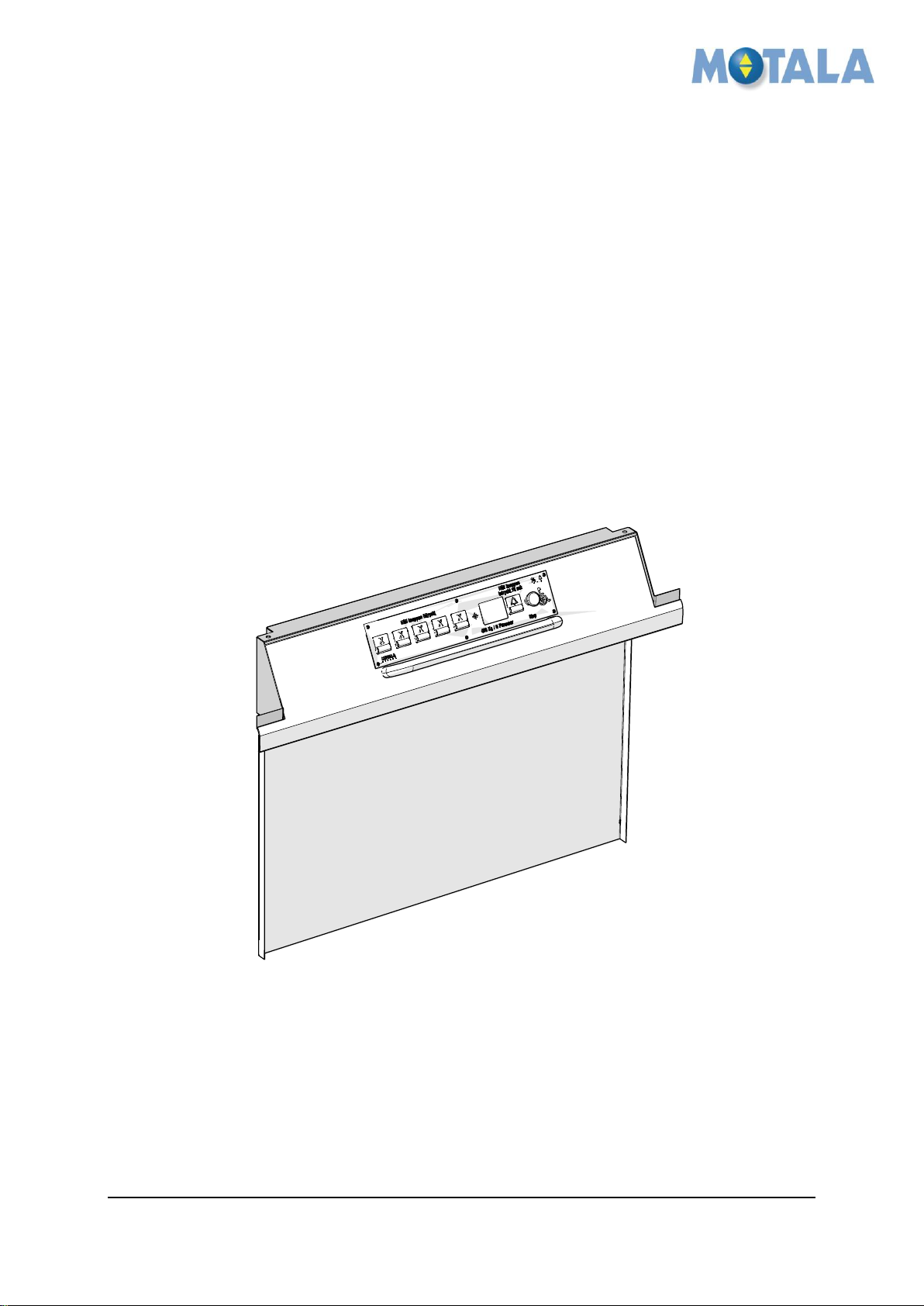
FIT THE COP AND HANDRAIL ...................................................................................... 10
INSTALL THE COP PANEL STEP 1 ............................................................................... 11
INSTALL THE COP PANEL STEP 2 ............................................................................... 11
INSTALL THE COP PANEL STEP 3 ............................................................................... 12
INSTALL THE COP PANEL STEP 4 ............................................................................... 12
INSTALL THE COP PANEL STEP 5 ............................................................................... 13
INSTALL THE COP PANEL STEP 6 ............................................................................... 13
5. APPROVALS AND VERSION HISTORY .............................................................. 14
© 2012 Motalahissar AB 2 (14) IQ56-04 Rev: B

MOTALA MC2000 – Updated version of the platform wall
Number
Description
View
100223
Staps 4,2x14 CS Ph2
100226
Staps 4,2x25 CS Ph2
100132
MC6S M5x14 FZB
100137
M6S M6x10 FZB DIN
100260
AZ 5,3 FZB
102332
SR 2604
101924
Secufast M5x12
100158
M6S M8x20 FZB DIN
Instruction
1. GENERAL
This new platform wall is specially designed to achieve a better and easier installation and
give the platform a better look. Follow this instruction carefully to ensure an efficient and
trouble-free installation.
Related documents
This instruction is to be used with the MC2000 installation instruction and the electrical
drawings.
2. SAFETY
Personal safety precautions for fitters.
Always use Personal Protective Equipment (PPE). Always use Head protection, Eye
protection, Foot protection, Hand protection, Protective clothing, Face shield and
Safety harness.
Follow the safety precautions in the MC2000 installation instruction.
3. Fasteners used in the installation instruction
© 2012 Motalahissar AB 3 (14) IQ56-04 Rev: B
MOTALA MC2000 – Updated version of the platform wall
Install the overload arm
1. Fit the overload arm from the
underside of the platform, use 2x
100233 so that it still can be
adjusted.
2. Route the cable from the
sensitive edges inside the arm.
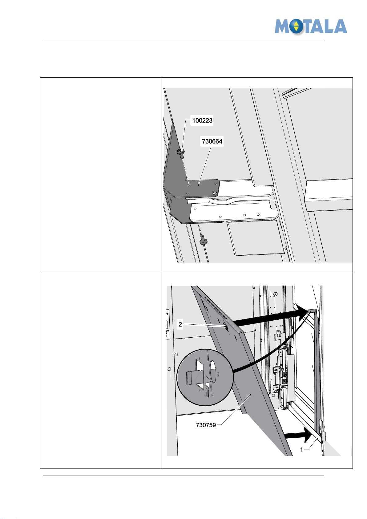
Install the platform wall
1. Fit the lower part of the wall
730759 so it abuts the platform
floor edge (1).
2. Fit the overload arm into the
hole (2) in the platform wall.
Instruction
4. Installation
© 2012 Motalahissar AB 4 (14) IQ56-04 Rev: B

MOTALA MC2000 – Updated version of the platform wall
Attach the traveling cable
1. Tread the traveling cable through
the hole (1) and fix it with the
cable clamp 730764, use 1x
100132.
2. Note, no cables are visible in this
illustration.
Sensitive edge cable
1. Thread the cable from the floor
sensitive edge contacts through
the hole. Stretch it and lock it
with a cable tie.
2. Note, no cables are visible in this
illustration.
Instruction
© 2012 Motalahissar AB 5 (14) IQ56-04 Rev: B

MOTALA MC2000 – Updated version of the platform wall
Fit the shelf
1. Fit the shelf 731072, use 5x
100223.
Fit the angle brackets
1. Fit the angel brackets 2x 730767,
one on the left and one on the
right side, use 4x100137 and 4x
100223.
2. Route the cables from the
magnet sensors, end limit switch
and retiring ramp together with
the fixings.
Instruction
© 2012 Motalahissar AB 6 (14) IQ56-04 Rev: B

MOTALA MC2000 – Updated version of the platform wall
Install the switch unit for the
upper sensitive edge
1. Fit the unit 730781, use 2x
100223.
Fit the switch for the over load
device
1. Fit the switch unit 730669, use 2x
100223.
Instruction
© 2012 Motalahissar AB 7 (14) IQ56-04 Rev: B

MOTALA MC2000 – Updated version of the platform wall
Fix the overload arm
1. Fix the overload arm, use 6x
100223.
Fit the earth terminal and
circuits board
1. Fit the earth terminal 100732,
use 1x 100260 and 1x 100938.
2. Fit fasteners for circuit boards, 6x
102332 on the shelf.
3. Fit the circuit board 102475.
4. Connect the cables to the PCB
terminals. See electrical drawings
for connection points.
Instruction
© 2012 Motalahissar AB 8 (14) IQ56-04 Rev: B
MOTALA MC2000 – Updated version of the platform wall
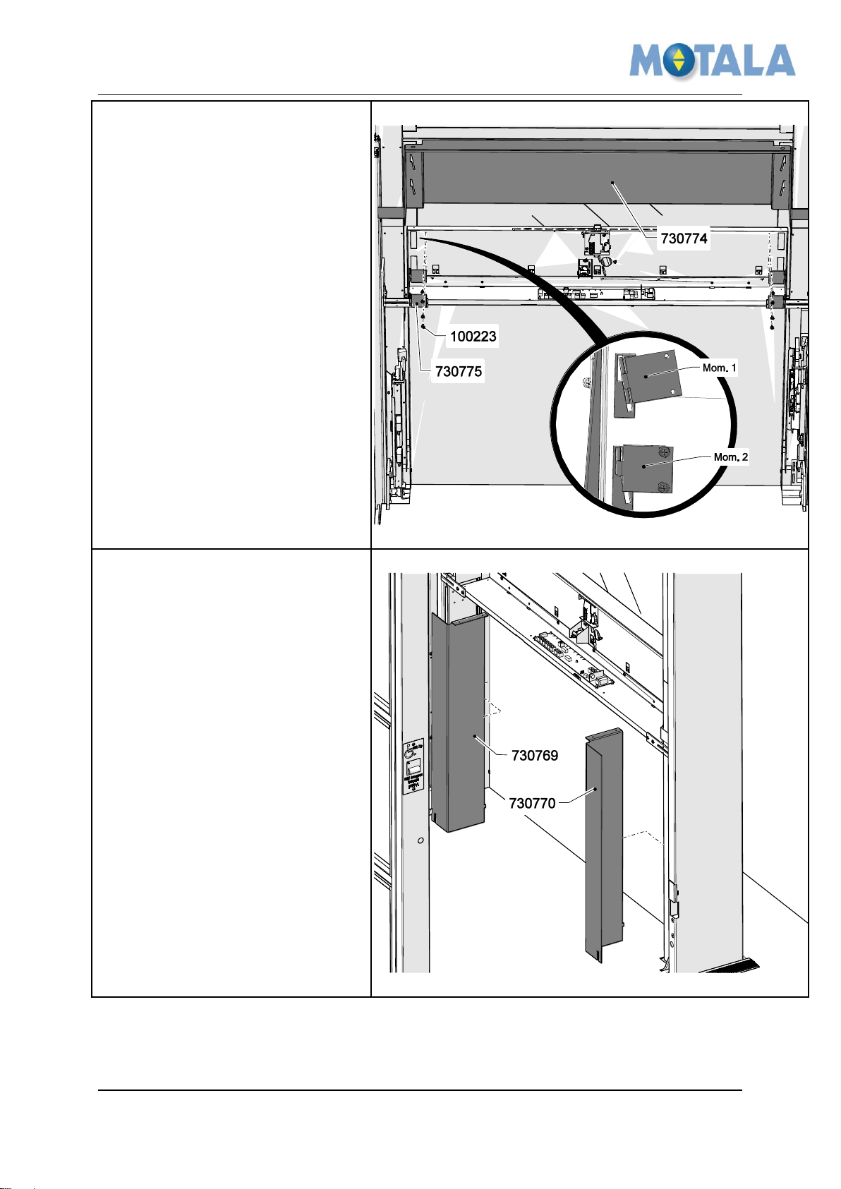
Fit the upper sensitive edge
1. Fit the upper sensitive edge
730774, use 4x 730775 and 8x
100223. Se Mom. 1 and Mom. 2.
Place the side panels
1. Place the left 730769 and right
730770 side panel after that you
are satisfied with floor magnets,
limit and lock arm positions.
Note! If you want to drive and
adjust from the platform COP
you may have to fit these panels
temporary for getting the COP
etc in right place.
Instruction
© 2012 Motalahissar AB 9 (14) IQ56-04 Rev: B
MOTALA MC2000 – Updated version of the platform wall
Fix the side panels
1. Insert the hook into the groove.
2. Fasten the side panels, use 4x
100223.
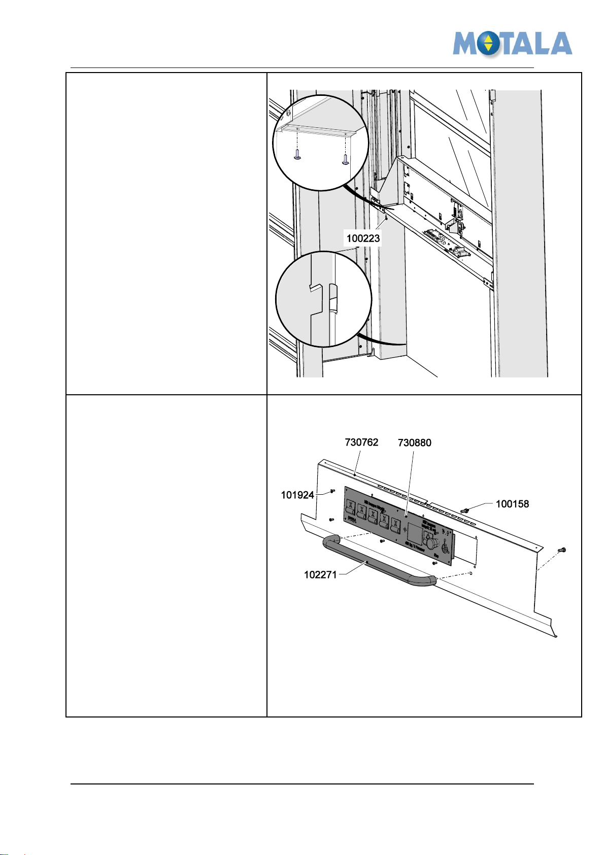
Fit the COP and handrail
1. Fit the COP 730880 on the panel
730762, use 6x 101924.
2. Fit the hand rail 102271, use 2x
100158.
Instruction
© 2012 Motalahissar AB 10 (14) IQ56-04 Rev: B
MOTALA MC2000 – Updated version of the platform wall
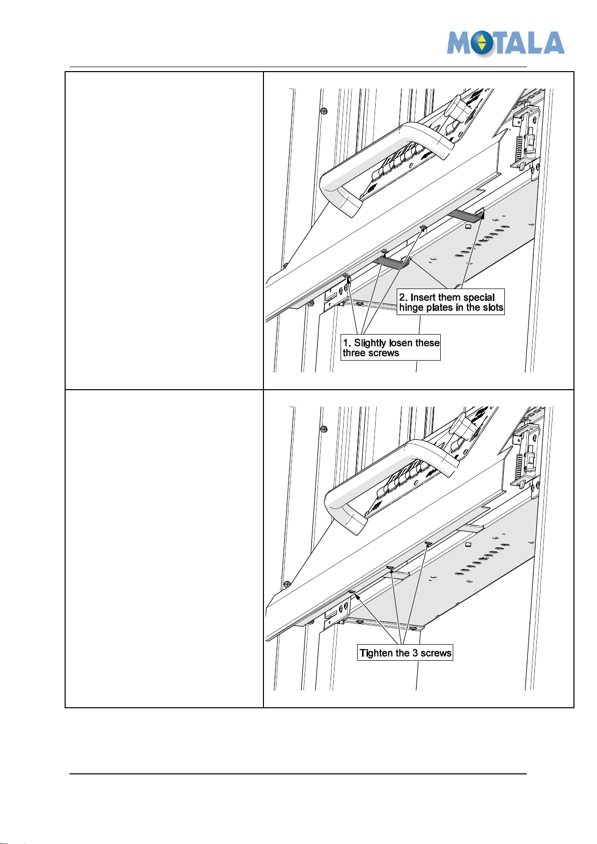
Install the COP panel step 1
1. Slightly loosen the 3 screws
under the COP panel.
2. Insert them special hinge plates
in the slots.
Install the COP panel step 2
1. Tighten the 3 screws.
Instruction
© 2012 Motalahissar AB 11 (14) IQ56-04 Rev: B
MOTALA MC2000 – Updated version of the platform wall
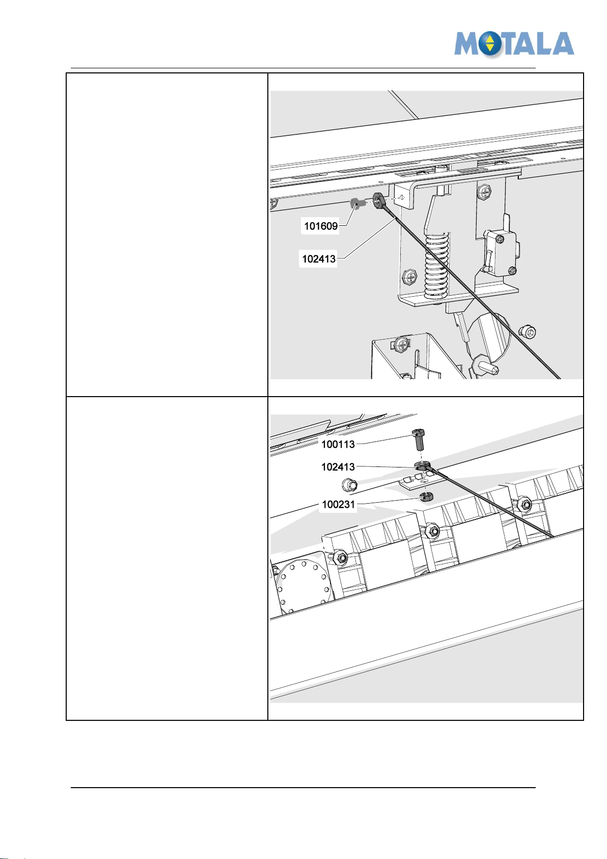
Install the COP panel step 3
1. Apply one end of the wire
102413 to the wall, use 1x
101609.
Install the COP panel step 4
1. Apply the other end of the wire
102413 to the COP, use 1x
100113 and 1x 100231 .
2. Connect the cables from the COP
to the PCB terminals. See
electrical drawings for
connection points.
Instruction
© 2012 Motalahissar AB 12 (14) IQ56-04 Rev: B
MOTALA MC2000 – Updated version of the platform wall
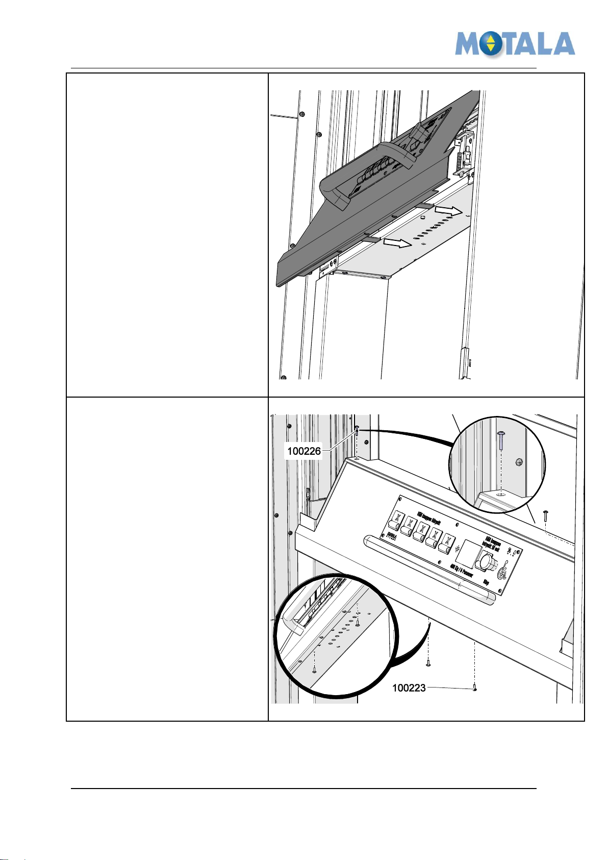
Install the COP panel step 5
1. Slide in the COP in until it stops,
let the edge of the plate slide in
under the sensitive edge.
Install the COP panel step 6
1. Fix the COP, use 2x 100226 and
2x 100223.
Instruction
© 2012 Motalahissar AB 13 (14) IQ56-04 Rev: B

MOTALA MC2000 – Updated version of the platform wall
Rev
Date
Description of change
Ref CR
Checked by
Approved by
-
2012-09-26
Draft 1.0
9340
Niklas Adell
Ari Nieminen
A
2013-01-15
Modified to fit Kinds equipment
9340
Niklas Adell
Ari Nieminen
B
2013-02-21
Added information about electrical
connections,
9340
Johan
Strömberg
Ari Nieminen
C
Instruction
5. APPROVALS AND VERSION HISTORY
Compiled by: Designer/Ronnie Sundström
© 2012 Motalahissar AB 14 (14) IQ56-04 Rev: B
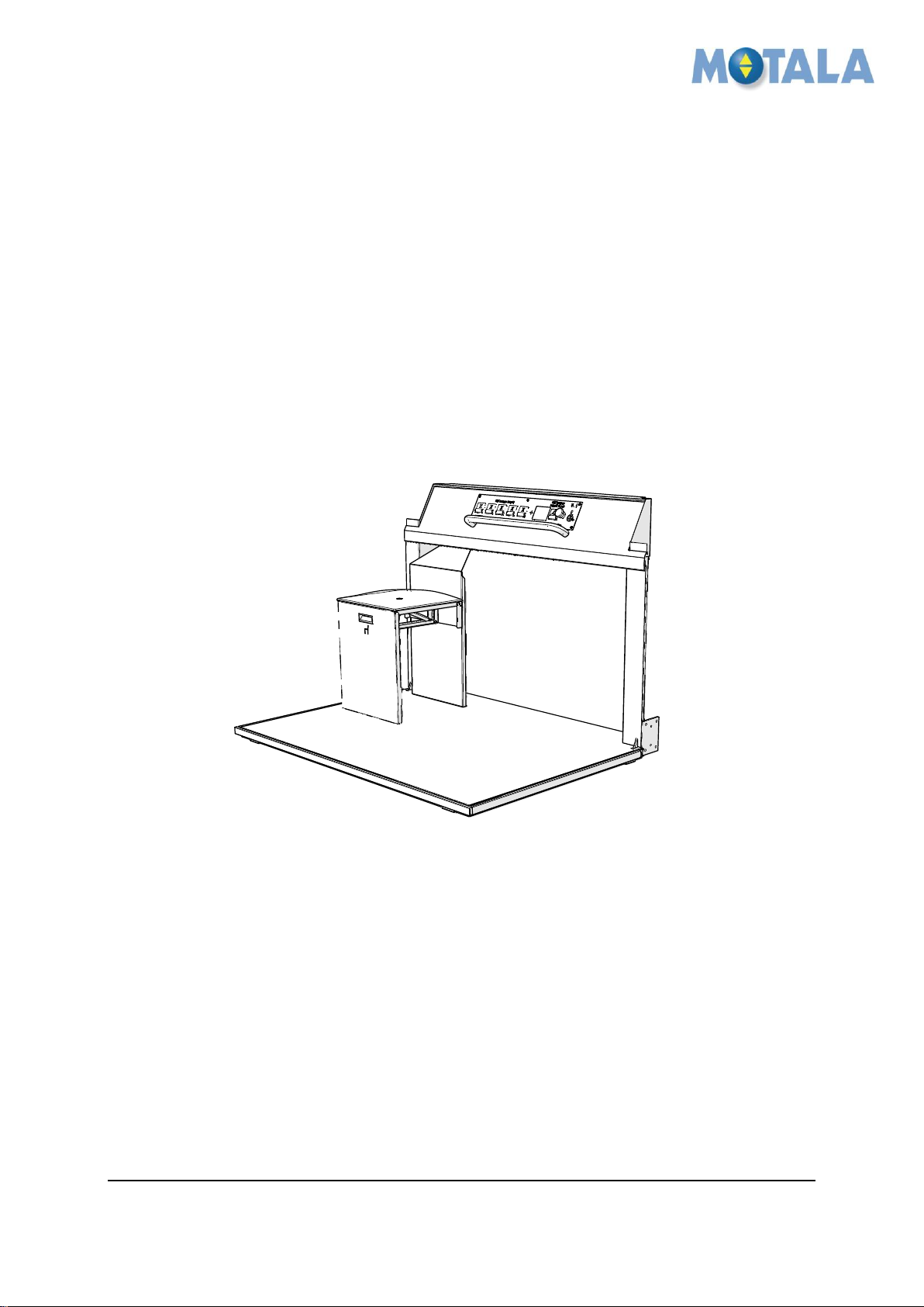
MOTALA MC2000 – Flip chair on the platform
Instruction
MC2000 - Flip chair on the platform
Rev. -
© 2012 Motalahissar AB 0 (6) IQ56-06
Rev: -

MOTALA MC2000 – Flip chair on the platform
Instruction
All rights reserved.
No part of the contents of this document may be copied, reproduced or transmitted in any form or by
any means, or translated into another language or format, in whole or part, without prior written
permission of MOTALA HISSAR Corporation.
CONTACT:
MOTALA HISSAR AB
Luxorgatan 1
BOX 4029
591 04 MOTALA
+46 141 23 70 50
www.motalahissar.se
© 2012 Motalahissar AB 1 (6) IQ56-06
Rev: -

MOTALA MC2000 – Flip chair on the platform
Instruction
TABLE OF CONTENTS
1. GENERAL .................................................................................................................3
RELATED DOCUMENTS ..................................................................................................3
2. SAFETY .....................................................................................................................3
3. FASTENERS USED IN THE INSTALLATION INSTRUCTION ................................3
4. INSTALLATION ........................................................................................................4
REMOVE THE COP .......................................................................................................4
FIT THE CONSOL ...........................................................................................................4
MOUNT THE FLIP CHAIR ................................................................................................5
TEST THE FLIP CHAIR ....................................................................................................5
REFIT THE COP AND MAKE A FUNCTION TEST OF THE COP ............................................6
5. APPROVALS AND VERSION HISTORY .................................................................6
© 2012 Motalahissar AB 2 (6) IQ56-06
Rev: -
MOTALA MC2000 – Flip chair on the platform
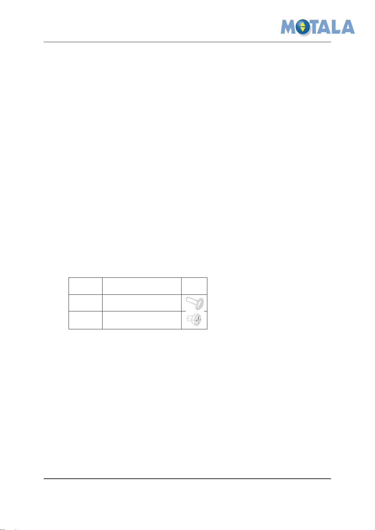
Number
Description
View
100223
Staps 4,2x14 CS Ph2
101725
RXK B8x9 FZB
Instruction
1. GENERAL
This flip chair is special designed to fit on MC2000 platform. Follow this instruction carefully
to ensure an efficient and trouble-free installation.
Related documents
This instruction is to be used with the MC2000 installation instruction and IQ56-04 Updated
version of the platform wall MC2000 installation instruction.
2. SAFETY
Personal safety precautions for fitters.
Always use Personal Protective Equipment (PPE). Always use Head protection, Eye
protection, Foot protection, Hand protection, Protective clothing, Face shield and
Safety harness.
Follow the safety precautions in the MC2000 installation instruction.
3. Fasteners used in the installation instruction
© 2012 Motalahissar AB 3 (6) IQ56-06
Rev: -

MOTALA MC2000 – Flip chair on the platform
Remove the COP
1. Remove the COP to be able to
install the consol for the flip
chair. Refer to document IQ56-04
Updated version of the platform
wall MC2000 installation
instruction.
Fit the consol
1. Fit the consol 731093 by using 2x
100223 in the pre-drilled holes in
the platform wall.
2. Make sure the consol I vertical by
using a spirit level before fitting
the lower part of the consol by
using 3x 100223. (you might have
to mark and drill holes before
fitting the screws in the platform
floor).
Instruction
4. Installation
© 2012 Motalahissar AB 4 (6) IQ56-06
Rev: -
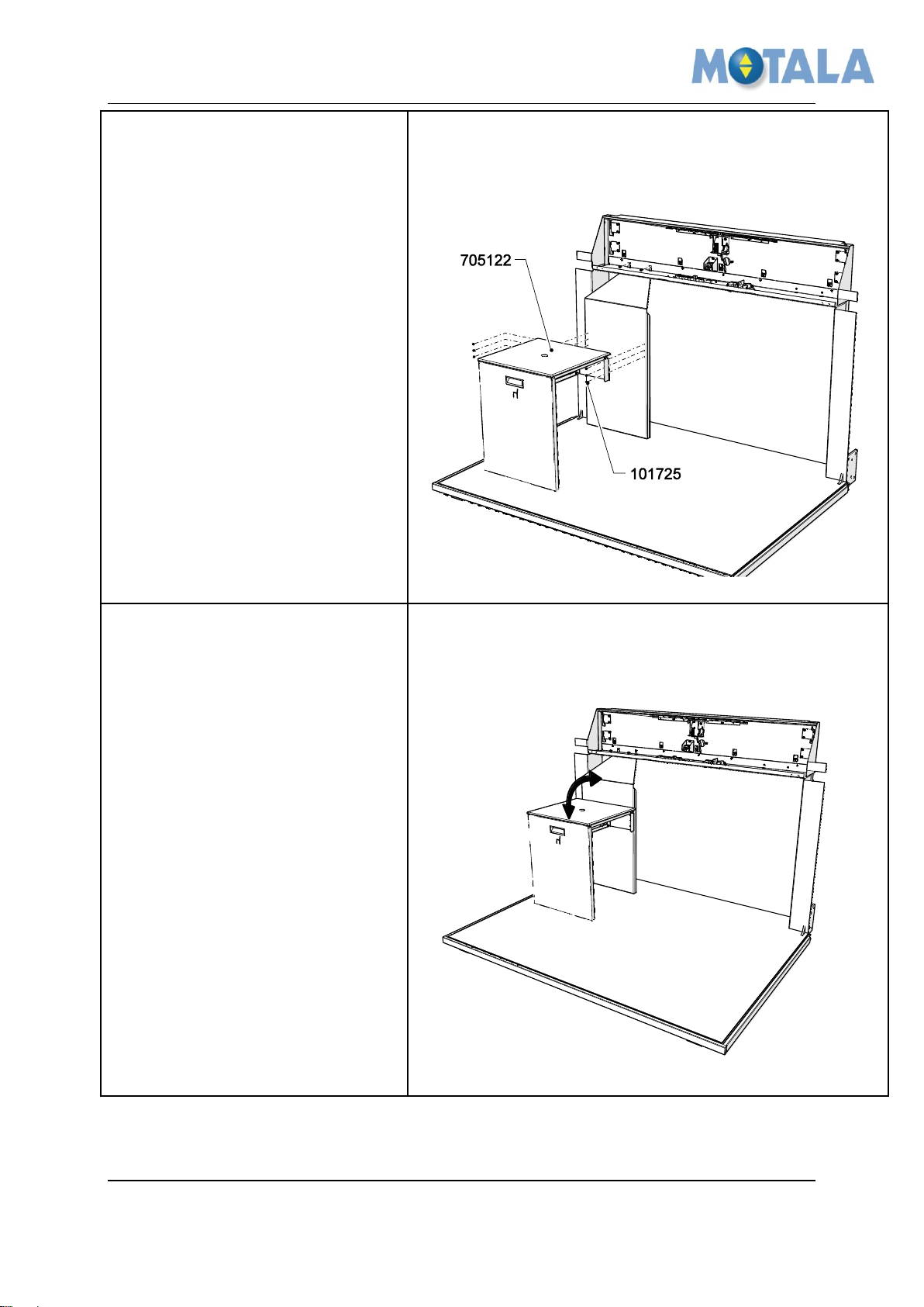
MOTALA MC2000 – Flip chair on the platform
Mount the flip chair
1. You have to tension the flip chair
apart to be able to fit the screws,
use 6x 101725. It is easier to be
two persons doing this phase of
the installation.
Test the flip chair
1. Test the flip chair by pull it out
and push all the way to the floor.
2. Then test that the gas spring
brings the flip chair up again.
3. In the upper retracted position
the flip chair must be hold in
position by the magnets.
Instruction
© 2012 Motalahissar AB 5 (6) IQ56-06
Rev: -

MOTALA MC2000 – Flip chair on the platform
Refit the COP and make a
function test of the COP
1. Refit the COP in its original
position, se document IQ56-04
Updated version of the platform wall
MC2000 installation instruction.
2. Test the function of the COP.
3. Installation is finished.
Rev
Date
Description of change
Ref CR
Checked by
Approved by
-
2013-01-18
First edition
13337
Niklas Adell
Ari Nieminen
A
B
C
Instruction
5. APPROVALS AND VERSION HISTORY
Compiled by: Designer/Ronnie Sundström
© 2012 Motalahissar AB 6 (6) IQ56-06
Rev: -

MOTALA MC2000 – Exclusive option for the plattform
Instruction
MC2000 - Exclusive option for the platform
Rev. -
© 2012 Motalahissar AB 0 (6) IQ56-07 Rev: -

MOTALA MC2000 – Exclusive option for the plattform
Instruction
All rights reserved.
No part of the contents of this document may be copied, reproduced or transmitted in any form or by
any means, or translated into another language or format, in whole or part, without prior written
permission of MOTALA HISSAR Corporation.
CONTACT:
MOTALA HISSAR AB
Luxorgatan 1
BOX 4029
591 04 MOTALA
+46 141 23 70 50
www.motalahissar.se
© 2012 Motalahissar AB 1 (6) IQ56-07 Rev: -

MOTALA MC2000 – Exclusive option for the plattform
Instruction
TABLE OF CONTENTS
1. GENERAL .................................................................................................................3
RELATED DOCUMENTS ..................................................................................................3
2. SAFETY .....................................................................................................................3
3. FASTENERS USED IN THE INSTALLATION INSTRUCTION ................................3
4. INSTALLATION ........................................................................................................4
FIT SIDE PANELS AND COP ...........................................................................................4
FIT THE EXCLUSIVE WALL STEP 1 ...................................................................................5
FIT THE EXCLUSIVE WALL STEP 2 ...................................................................................5
FINAL CHECK ...............................................................................................................6
5. APPROVALS AND VERSION HISTORY .................................................................6
© 2012 Motalahissar AB 2 (6) IQ56-07 Rev: -

MOTALA MC2000 – Exclusive option for the plattform
Number
Description
View
- - -
Instruction
1. GENERAL
This exclusive option is special designed to fit on MC2000 platforms. Follow this instruction
carefully to ensure an efficient and trouble-free installation.
Related documents
This instruction is to be used with the MC2000 installation instruction and IQ56-04 Updated
version of the platform wall MC2000 installation instruction.
2. SAFETY
Personal safety precautions for fitters.
Always use Personal Protective Equipment (PPE). Always use Head protection, Eye
protection, Foot protection, Hand protection, Protective clothing, Face shield and
Safety harness.
Follow the safety precautions in the MC2000 installation instruction.
3. Fasteners used in the installation instruction
See document IQ56-04 Updated version of the platform wall MC2000 installation instruction.
© 2012 Motalahissar AB 3 (6) IQ56-07 Rev: -
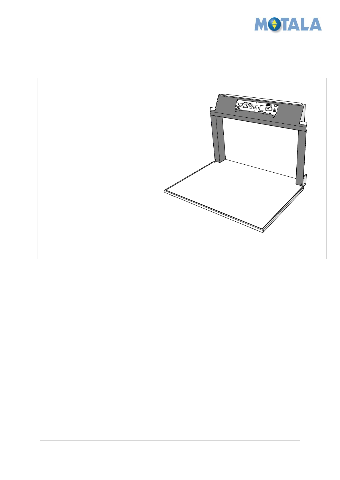
MOTALA MC2000 – Exclusive option for the plattform
Fit side panels and COP
1. Remove the plastic cover from
the stainless steel plates and
check for scratches. Fit the side
panels (stainless steel), handrail
(stainless steel or oak) and the
COP (stainless steel). Se
document IQ56-04 Updated
version of the platform wall
MC2000 installation instruction
Instruction
4. Installation
© 2012 Motalahissar AB 4 (6) IQ56-07 Rev: -
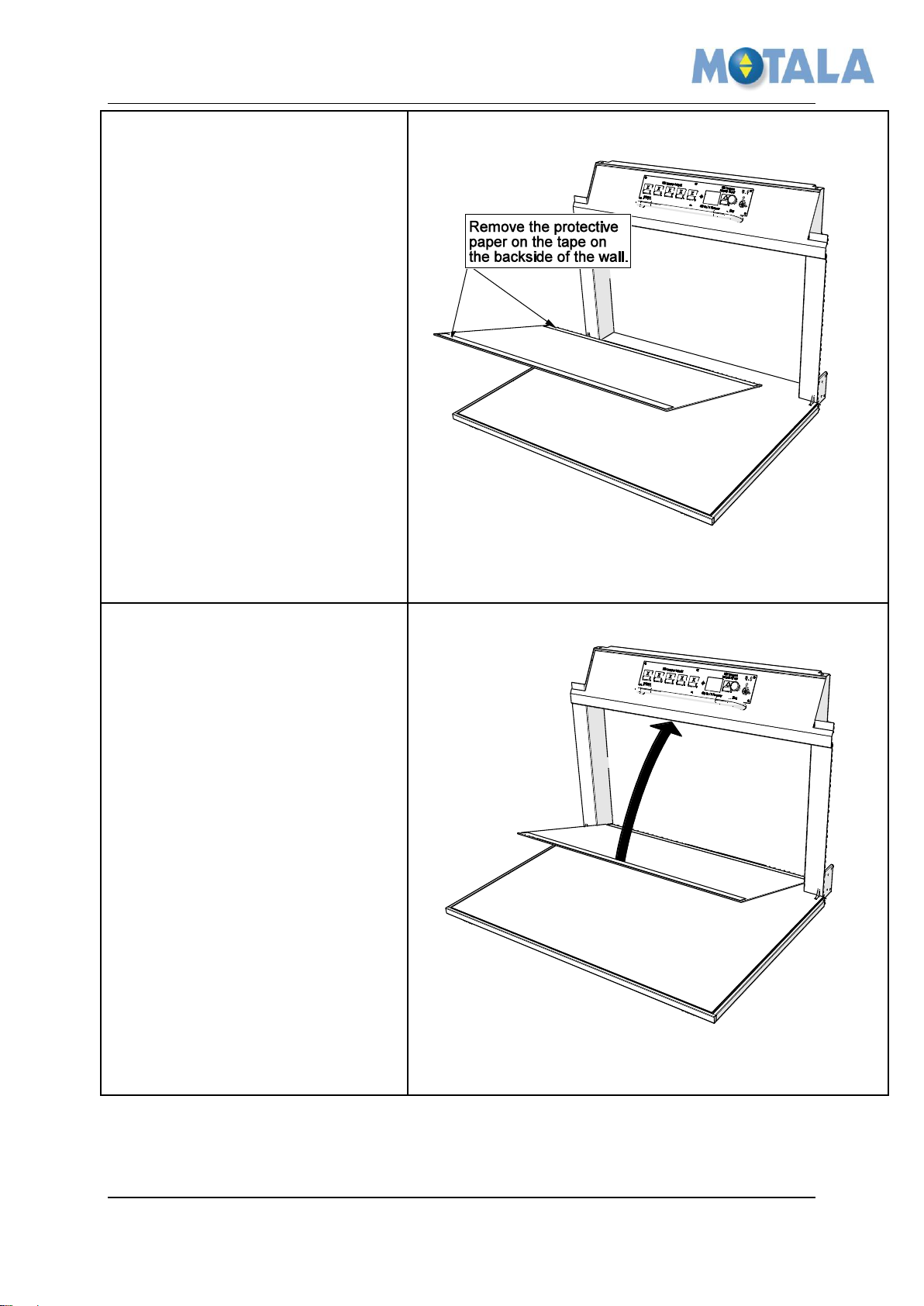
MOTALA MC2000 – Exclusive option for the plattform
Fit the exclusive wall step 1
1. Remove protective paper from
tape.
Fit the exclusive wall step 2
1. Fit the lower part of the exclusive
wall in the corner of the floor and
the wall and tape it to the wall of
steel.
Instruction
© 2012 Motalahissar AB 5 (6) IQ56-07 Rev: -
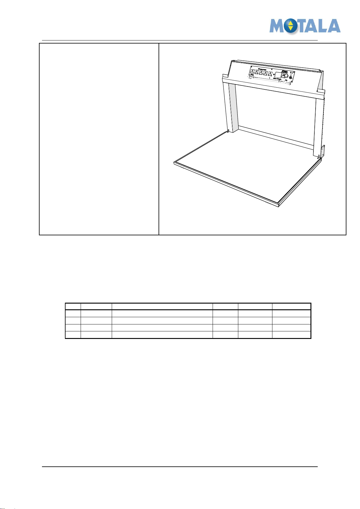
MOTALA MC2000 – Exclusive option for the plattform
Final check
1. Check the installation for
scratches.
2. Wash away fingerprints and
other dirt from the platform
before leaving the site.
Rev
Date
Description of change
Ref CR
Checked by
Approved by
-
2013-01-21
First edition
13339
Niklas Adell
Ari Nieminen
A
B
C
Instruction
5. APPROVALS AND VERSION HISTORY
Compiled by: Designer/Ronnie Sundström
© 2012 Motalahissar AB 6 (6) IQ56-07 Rev: -
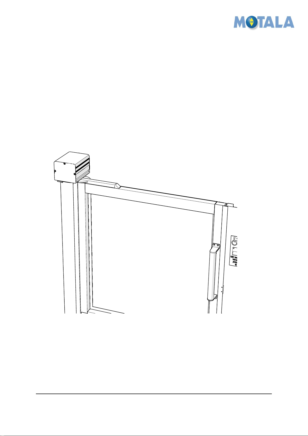
MOTALA MC2000 Automatic door operator when headroom
is 1300mm (so-called “half door”)
Instruction
MC2000 – Automatic door operator –
Headroom 1300 mm (half door)
Rev. -
© 2012 Motalahissar AB 0 (6) IQ56-08
Rev: -
 Loading...