

Page 1
M3605 operating manual V1.01e 1
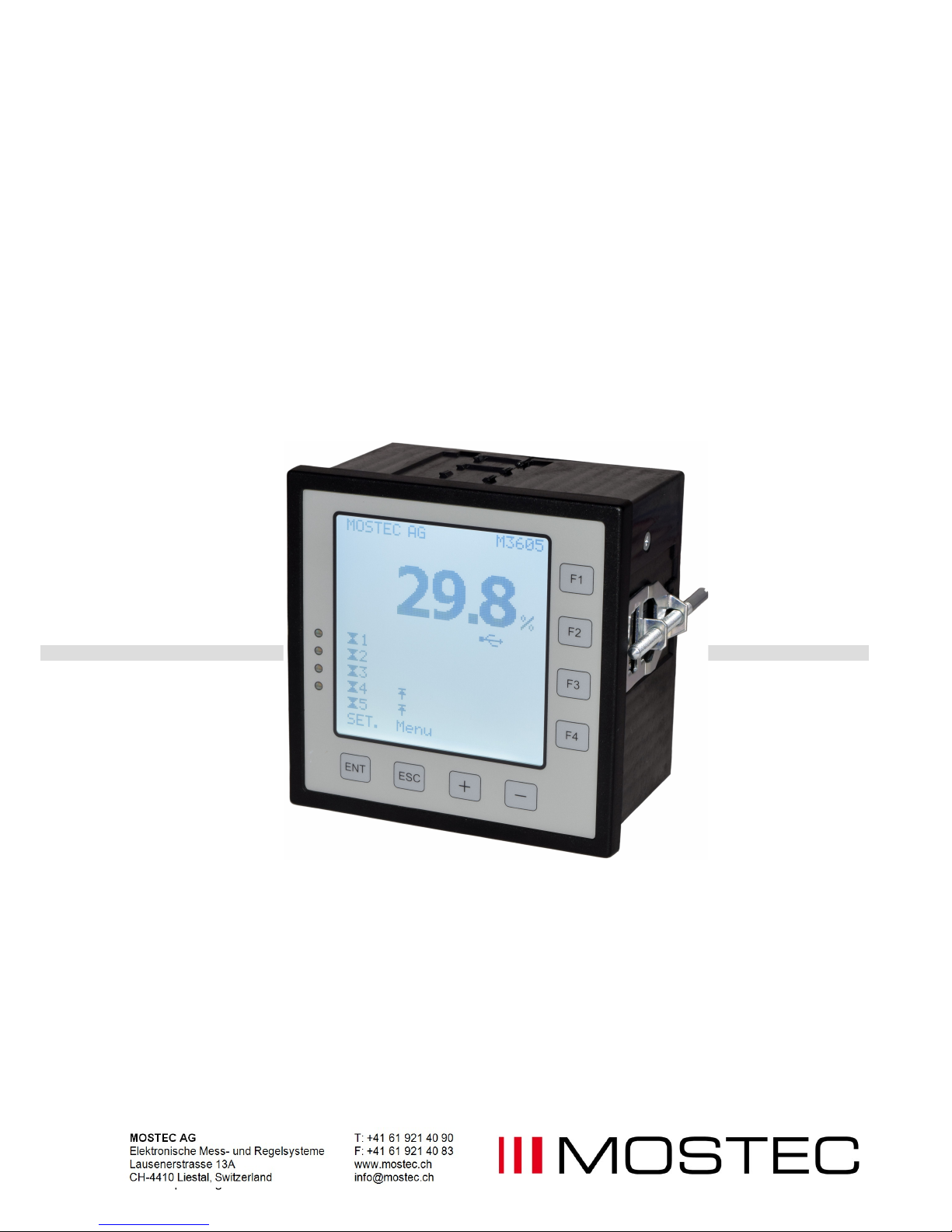
Operating Manual
Digital display unit
M3605
with five limit contacts
Page 2

M3605 operating manual V1.01e 2
Warranty
Mostec warrants this product to be free of manufacturing defects for a 2-year period after
the original date of purchase. Within this period, defective products will be repaired free
of charge provided that the defect occurred during normal operation. This warranty does
not cover damage to the product resulting from ordinary usage such as front panel
scratches, broken control elements and corrosion, etc. The customer is responsible for
shipping and packing charges for products returned under warranty to Mostec. Mostec
warrants this product beyond the 2-year warranty period for an additional 2 years in case
of long term damages due to improper manufacturing. Such damages as poorly soldered
joints or other assembly problems are also covered by the warranty. Transportation
damages are not covered by the warranty and should be referred to the respective
delivery service.
Page 3

M3605 operating manual V1.01e 3
Index: Page
A. Front Elements And Keyboard ............................................................................................ 4
B. Setup menu, setting the limits of the instruments ................................................................ 5
C. User Menu ........................................................................................................................... 6
Measurement settings ......................................................................................................... 6
Relay 1-5 settings................................................................................................................ 6
USB settings ....................................................................................................................... 6
Instrument settings .............................................................................................................. 6
D. Measurement settings ......................................................................................................... 7
Input range display .............................................................................................................. 7
Display range ...................................................................................................................... 7
Decimal point display .......................................................................................................... 7
Unit display .......................................................................................................................... 7
Input range signal ................................................................................................................ 7
Output range signal ............................................................................................................. 7
E. Relay Settings ..................................................................................................................... 8
F. USB settings........................................................................................................................ 9
Time setup ........................................................................................................................... 9
Date setup ........................................................................................................................... 9
Data log period .................................................................................................................... 9
Remove thumb drive ........................................................................................................... 9
USB characteristics ............................................................................................................. 9
B. USB error code .......................................................................................................... 9
G. Instrument settings ............................................................................................................ 10
Keyboard lock/unlock ........................................................................................................ 10
Language setting ............................................................................................................... 10
Customer label .................................................................................................................. 10
Factory setting ................................................................................................................... 10
Device info ........................................................................................................................ 10
6/6 ..................................................................................................................................... 10
Contrast ............................................................................................................................. 10
H. Factory Settings ................................................................................................................ 11
I. Mechanical Dimensions .................................................................................................... 12
J. Technical Data ................................................................................................................... 14
Page 4
M3605 operating manual V1.01e 4
A. Front Elements And Keyboard
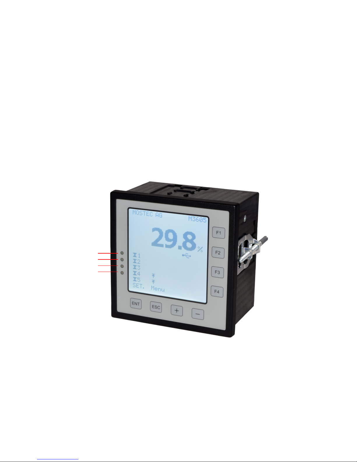
This listing only refers to the main screen, which shows up 3 seconds after power on.
Nr. Element Function Page
a. LED1 Errors, limit contacts, USB, wire break b. LED2 no function c. LED3 no function
d. LED4 no function
F1 setup menu, direct display of limit contact 1 value 5
F2 setup menu, direct display of limit contact 2 value 5
F3 setup menu, direct display of limit contact 3 value 5
F4 setup menu, direct display of limit contact 4 value 5
ENT display the setup menu, input 5
ESC display the main menu, exit 6
+ plus 5-12
- minus 5-12
a
b
c
d
Page 5
M3605 operating manual V1.01e 5
B. Setup menu, setting the limits of the instruments
The M3605 has 3 ways to change the limit values of the limit contacts. To make the handling of
the instrument simple, we have made a direct entry into the cursor menu available.
To enter the cursor menu below, you can either press the enter (ENT) key which leads you to
limit contact 1 directly. By pressing (ENT) again, limit contact 2 can be changed and so on until
limit contact 5.
By pressing (F1 to F4) you end up in the same menu, but directly on the desired limit contact.
Example: (F1) leads to limit contact 1, (F3) leads to limit contact 3 etc.
The third way, to set up the limit value is done by pressing the (ESC) key for more than 3
seconds. Then move with the arrow (+) / (-) keys to “Relay (Nr. of desired contact) settings”, press the
(ENT) key and move with the arrow (+) / (-) keys to “Rel (Nr. of desired contact): set point”. Then
press the (ENT) key again and change the limit value. Confirm with (ENT), skip with (ESC).
Quit the setup menu by pressing (ESC), or, wait a few seconds with no key operation. Values
can be altered with (+) and (-), or, depending on the menu, with the (F3) and (F4) as well.
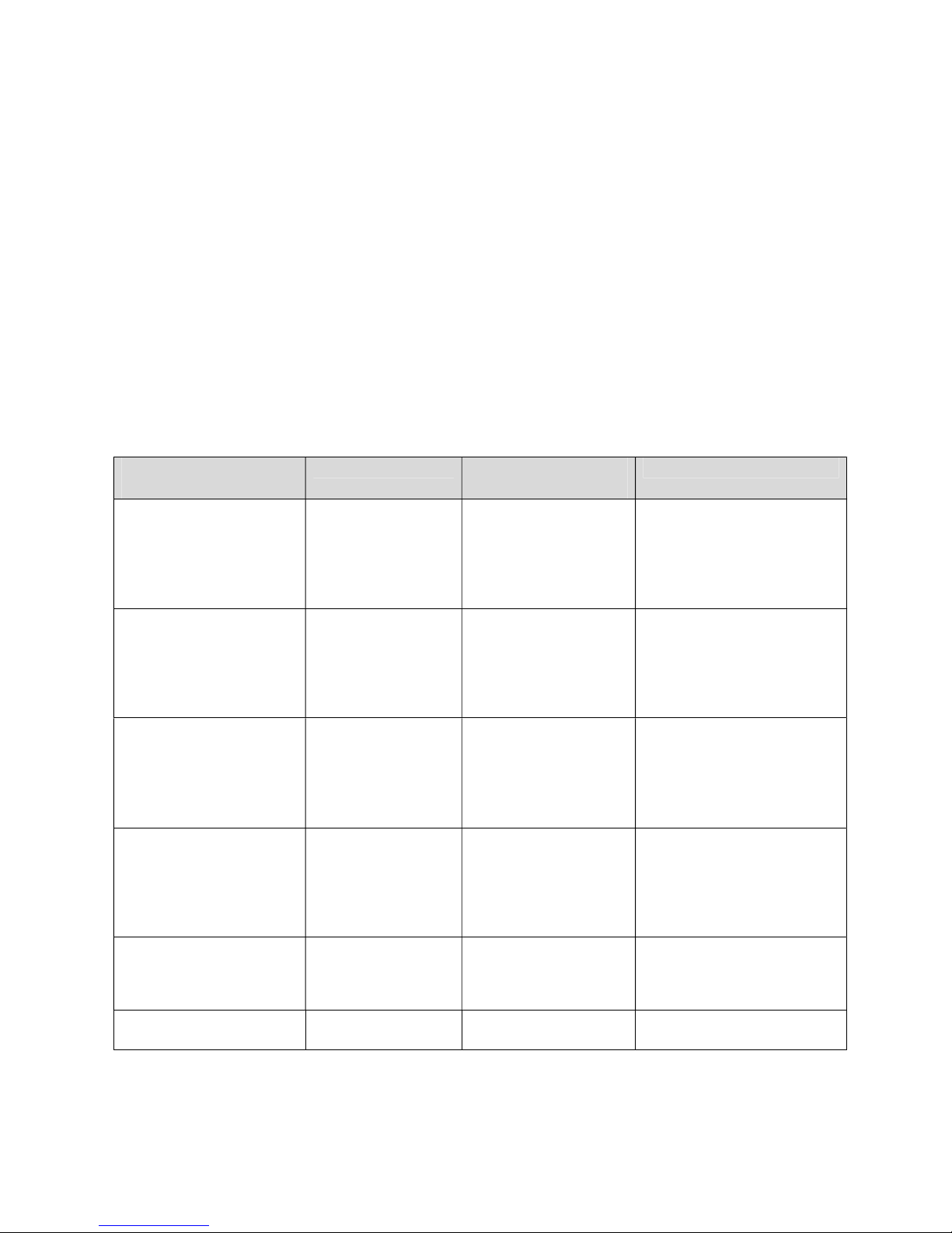
Access to the
menu item
Menu Item Display Reaction Change Values
press ENT 1x set limit contact
value 1
Limit 1 can also be
set by (F1) direct
LMT1 symbol blinks
Limit value is displayed
Adjust the value with (+)
and (-) .
(F1) or (ENT) saves the
settings
press ENT 2x set limit contact
value 2
Limit 2 can also be
set by (F2) direct
LMT2 symbol blinks
Limit value is displayed
Adjust the value with (+)
and (-).
(F2) or (ENT) saves the
settings
press ENT 3x set limit contact
value 3
Limit 3 can also be
set by (F3) direct
LMT3 symbol blinks
Limit value is displayed
Adjust the value with (+)
and (-).
(F3) or (ENT) saves the
settings
press ENT 4x
set limit contact
value 4
Limit 4 can also be
set by (F4) direct
LMT4 symbol blinks
Limit value is displayed
Adjust the value with (+)
and (-).
(F4) or (ENT) saves the
settings
press ENT 5x
set limit contact
value 5
LMT5 symbol blinks
Limit value is displayed
Adjust the value with (+)
and (-).
(ENT) saves the settings
press ENT 6x
USB
USB-symbol blinks Set the USB logger on/off
Page 6

M3605 operating manual V1.01e 6
C. User Menu
Access to menu: press and hold (ENT) for 3 seconds
Navigation in the menu: (+) and (-)
Access to a menu item: (ENT) = ENTER
Exit a menu item: (ESC) = ESCAPE
Adjust values: (+) and (-)
Menue Item Submenue Function/Comment
1/8
Measurement settings
Input range display,
Display range,
Decimal point display,
Unit display,
Input range signal,
Output range signal
See section D
2-6/8
Relay 1-5 settings
Rel1-5: behavior
Rel1-5: set point
Rel1-5: norm/inv
Rel1-5: LED norm/inv
Rel1-5: turn on delay
Rel1-5: turn off delay
Rel1-5: hysteresis
Rel1-5: label
See section E
7/8
USB settings
Time setup
Date setup
Data log period
Remove memory stick
See section G
8/8
Instrument settings
Keyboard lock/unlock
Language settings
Custom label
Factory setting
Instrument info
Contrast
See section H
Page 7

M3605 operating manual V1.01e 7
D. Measurement settings
1) Press and hold (ESC) 3 seconds to enter the users menu.
2) Then you are already at item 1/8, ''Measurement settings''. If not move to 1/8 with (+).
3) Open menu item with (ENT)
4) Menu structure:
Example 1: Input: 4 … 18mA → Display: 1.70 … 5.60 % →Signal output: 4 … 20mA
Example 2: Input: 2.5V … 7.5V → Display: 37.5 ... 115.4 A →Signal output: 4 … 20mA
Menu Item Change Values Function/Comment
1/6
Input range display
Min: Set the minimum point:
Example 1:
The instruments input signal:
0 … 20mA
Requested range: 4 … 18mA
Now set the Min to:
(4mA : 20mA * 100%) = 20%
Max:
Set the maximum point:
(18mA : 20mA * 100%) = 90%
Min: 20% & Max: 90% leads
to a new range of 4 … 18mA
Example 2:
The instruments input signal:
0 … 10V
Requested range:
2.5 …. 7.5V
Min = (2.5V : 10V * 100%) = 25%
Max = (7.5V : 10V * 100%) = 75%
→ 25% … 75% leads to 2.5 …
7.5V
2/6
Display range
Set minimum display range in
the Example 1:
(only parts, ignore decimal pt)
Min: 170 (1.70 is desired)
Max: 560 (5.60 is desired)
Example 2:
(only parts ignore decimal pt)
Min: 375 (37.5 is desired)
Max: 1154 (115.4 is desired)
3/6
Decimal point display
Set the decimal point in the
Example 1:
XXX.X
XX.XX (1.70 is requested)
X.XXX
XXXX
Set the decimal point in the
Example 2:
XXX.X (37.5 is requested)
4/6
Unit display
Select the unit for the Display:
Start with the first character.
Use the (+) and (-) key to
select it (to the right the
number of the current
character can be seen)
1. Blank (character # 32)
then select the second
character with > (F3)
2. Percent symbol (char # 37)
Store with (ENT) (max. 4
characters).
Example 2:
(+) and (-) to select:
1. Blank (char # 32)
(F3) to move the cursor
(+) and (-) to select:
2. A (char # 65)
Store with (ENT)
5/6
Input range signal
Example 1:
Min: 1.70% with (+) and (-)
(ENT) to store and select
Max: 5.60% with (+) and (-)
store and leave with (ENT)
Example 2:
Min: 37.5A with (+) and (-)
(ENT) to store and select
Max: 115.4% with (+) and (-)
store and leave with (ENT)
6/6
Output range signal
Example 1:
Min: 4.0mA with (+) and (-)
(ENT) to store and select the
Max: 20.0mA with (+) and (-)
store and leave with (ENT)
Example 2:
Min: 4.0mA with (+) and (-)
(ENT) to store and select the
Max: 20.0mA with (+) and (-)
store and leave with (ENT)
Page 8
M3605 operating manual V1.01e 8
E. Relay Settings
1) Press and hold (ESC) 3 seconds to enter the customer menu.
2) Go to menu item 2/8 to 6/8, “Relay x settings” with (+)
3) Open menu item with (ENT)
4) To confirm a selection press (ENT), exit with (ESC)
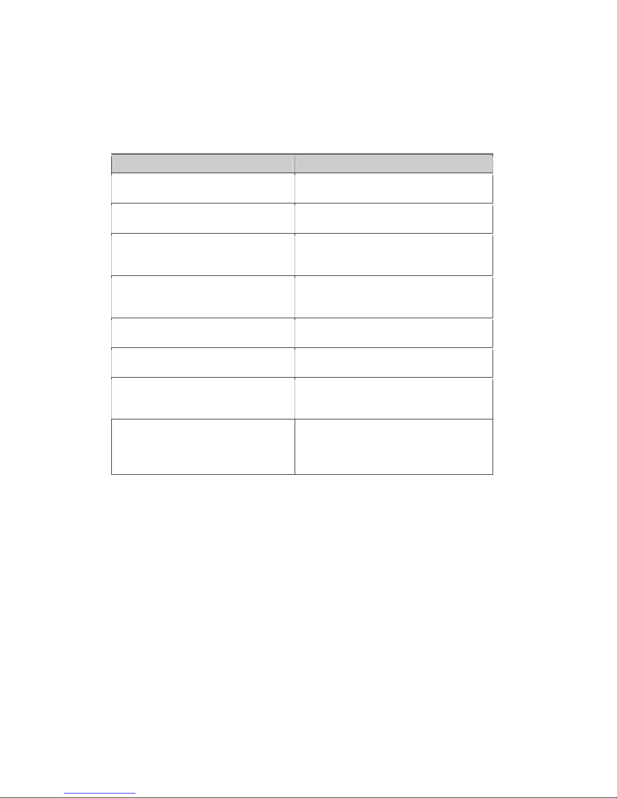
5) Menu structure:
Menue Item Change Values
1/8 Relay 1-5: behavior Switch with (+) between upper and lower
limit, confirm the selection with (ENT)
2/8 Relay 1-5: set point Change the set point value with (+) and
(-)
3/8 Relay 1-5: norm/inv? Switch with (+) between normal and
inverse operation and confirm the
selection with (ENT)
4/8 Relay 1-5: Led norm/inv? Switch with (+) between normal and
inverse operation and confirm the
selection with (ENT)
5/8 Relay 1-5: turn on delay Change the time delay with (+) and (-),
resolution is +/-1s
6/8 Relay 1-5: turn off delay Change the time delay with (+) and (-),
resolution is +/-1s
7/8 Relay 1-5: hysteresis
Change the hysteresis of both set points
with (+) and (-), possible resolution is 5 to
200 parts of range
8/8 Relay 1-5: label Change characters with (+) and (-) and
jump with (F3) and (F4) to the next
character, confirm the label text with
(ENT).
Page 9
M3605 operating manual V1.01e 9
F. USB settings
1) Press and hold (ESC) 3 seconds to enter the user menu.
2) Go to menu item 7/8 "USB settings" with (+).
3) Open menu item with (ENT)
4) To confirm a selection press (ENT), exit with (ESC)
5) Menu structure:
Menu Item Change Values Function/Comment
1/4
Time setup
Toggle with (+) between 12h and
24h format, confirm it with (ENT)
Set time format and time for logging
mode
2/4
Date setup
Toggle with (+) between
DDMMYY and MMDDYY format,
confirm with (ENT)
Set date format and date for logging
mode
3/4
Data log period
Set recording time interval with
(+) and (-) from5 to 7200sec .
Resolution: 1sec
4/4
Remove thumb drive
Toggle with (F3) between
stop/start logging
Close the current logging cycle before
removing the memory stick.
When the message ''USB: Start
logger?'' shows up, you may remove
the memory stick
USB characteristics
Device accepts empty and FAT32 formatted memory sticks only.
Date and clock settings remain stored up to 3 hours without power supply connection
Set date and time before recording with the memory stick.
Device starts automatically with logging data when memory stick is connected.
: Wait with removing the memory stick. It may take up to 5 minutes to write data to the stick.
Internal data sets are stored in CSV format every 15 minutes. The file name characteristics after a
secure ejection, removing the memory stick in the USB sub menu, are:
''JJMMDDXX.csv''
JJ = last 2 digit of current year
MM = current month
DD = current day
XX = file counter 0-99
Data will appear in a spreadsheet program as below:
* The unit and the limit contact label is adjusted according to the instruments settings
Date Time Value[ %]* 1*
2* 3* 4* 5*
04.07.2018 12:12:55 10.00 0
1 0 1 1
04.07.2018 12:13:03 10.01 1
1 0 1 0
04.07.2018 12:13:04 10.03 0
0 0 1 0
04.07.2018 12:13:06 10.15 1
0 1 1 1
04.07.2018 12:13:07 10.78 1
1 1 0 1
B. USB error code
E: xx
error description
01 drive not formatted
02 drive wrong formatted
03 drive is write protected
04 sector size not supported
Page 10
M3605 operating manual V1.01e 10
G. Instrument settings
1) Press and hold (ESC) 3 seconds to enter the user menu.
2) Go to menu item 8/8 "Device settings" with (+).
3) Open menu item with (ENT)
4) To confirm a selection press (ENT), exit with (ESC)
5) Menu structure:
Menu Item Change Values Function/Comment
1/6
Keyboard lock/unlock
Set a code with (+) and (-)
between 1 and 999 to lock or
unlock the device, confirm the
code with (ENT)
If the keyboard is locked, you
won't be able to make changes in
the settings, until you have
unlocked it with the valid code.
Note:
Please contact us if you forgot the
code. We will then provide a
factory unlock code.
2/6
Language setting
Set the required language
with (+) and (-)
3/6
Customer label
Change characters with (+)
and (-), switch position with
(F3) and (F4), confirm Text
with (ENT).
Shows a customer label on main
screen. Maximum 16 characters
are possible.
4/6
Factory setting
Sets all values to default,
confirm with (ENT) or exit with
(ESC)
5/6
Device info
Exit with (ENT)
Shows firmware version, serial
number and calibrating points.
6/6
Contrast
Change the contrast with (+)
and (-), confirm with (ENT)
Keep in mind, that you will not be
able to move back to this item if
you select a contrast which
makes the graphics on the screen
invisible (too dark or too bright)
Page 11

M3605 operating manual V1.01e 11
H. Factory Settings
(OEM factory settings can differ from the standard MOSTEC factory settings)
Measuring settings:
Input range display Min: 20.00%
Input range display Max: 100.00%
Display range Min: 0
Display range Max: 1000
Decimal point display: XXX.X
Unit display: “ %”
Input range signal Min: 0
Input range signal Max: 1000
Output range signal Min: 4.00mA
Output range signal Max: 20.00mA
→ leads to 4 … 20mA equals 0.0 to 100.0%
→ Signal output: 4 … 20mA
Relay 1 settings:
Rel 1: behavior upper limit
Rel 1: set point 80.0%
Rel 1: norm / inv normal
Rel 1: LED norm / inv normal
Rel 1: turn on delay 0s
Rel 1: turn off delay 0s
Rel 1: hysteresis 5
Rel 1: label “1 “
Relay 2 settings:
Rel 2: behavior upper limit
Rel 2: set point 60.0%
Rel 2: norm / inv normal
Rel 2: LED norm / inv normal
Rel 2: turn on delay 0s
Rel 2: turn off delay 0s
Rel 2: hysteresis 5
Rel 2: label “2 “
Relay 3 settings:
Rel 3: behavior upper limit
Rel 3: set point 40.0%
Rel 3: norm / inv normal
Rel 3: LED norm / inv normal
Rel 3: turn on delay 0s
Rel 3: turn off delay 0s
Rel 3: hysteresis 5
Rel 3: label “3 “
Relay 4 settings:
Rel 4: behavior upper limit
Rel 4: set point 20.0%
Rel 4: norm / inv normal
Rel 4: LED norm / inv normal
Rel 4: turn on delay 0s
Rel 4: turn off delay 0s
Rel 4: hysteresis 5
Rel 4: label “4 “
Page 12
M3605 operating manual V1.01e 12
Relay 5 settings:
Rel 5: behavior upper limit
Rel 5: set point 15.0%
Rel 5: norm / inv normal
Rel 5: LED norm / inv normal
Rel 5: turn on delay 0s
Rel 5: turn off delay 0s
Rel 5: hysteresis 5
Rel 5: label “5 “
USB settings:
Clock setup: 24h
Date setup: DDMMYY
Log period: 5s
Device settings:
Switch lock/unlock off
Language: English
Custom label: all Blanks
Contrast: 66
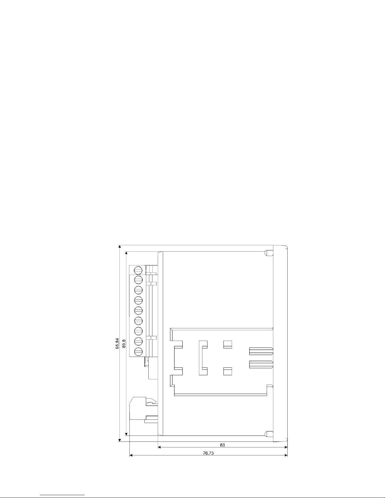
I. Mechanical Dimensions
Side view:
Page 13
M3605 operating manual V1.01e 13
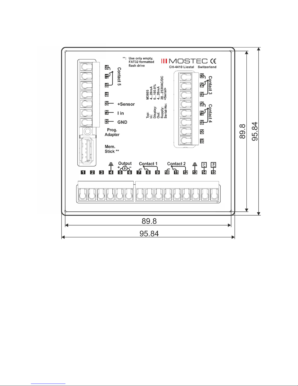
Rear view:
Page 14
M3605 operating manual V1.01e 14
J. Technical Data
Measuring ranges: 0/4 … 20mA free programmable
0 … 1 /10V or other signals on request
Imput load / impedance: Current signal = 51Ω; voltage signal = 1MΩ
2-Wire transmitter supply: 20VDC, max 25mA
Accuracy: ± 0.1% @ 23°C ambient temperature
Reproducibility: ± 0.1%
Temperature drift: Zero drift:30ppm/°C typical
Gain drift 25ppm/°C typical
Long-term stability: ± 0.1%
Working temperature range: -5°C to +45°C
Display: Graphic LCD 128x128 pixel
Pixel size: 0.4x0.4mm
Max. humidity: Non condensing
ENT key: Quick access to settings or to save parameters
ESC key: Access to the main menu, press and hold for 3 seconds, or exit menu item
+ / - key: Set values
F1-F4 key: Direct access to change the set point of relais 1 - 4
Signal current output: 0...20mA, galvanically isolated and adjustable over full range
Max load: <500Ω
Output impedance: Typ. >1MΩ
Relay contact: Adjustable over the full range
Hysteresis: 5 - 200 digits adjustable
Limit value status: Displayed with symbol on screen, LED’s not available
Relay outputs: Floating changeover contacts, max. 2A at 230VAC resistive load
USB: Logger function, programmable log-time, 5 to 7200 sec. Use only FAT32 formatted,
empty USB flash drives. Stop logging mode before removing.
Supply: 20..253VAC/DC, up to 4.5W
CE-conformity: Fullfilled
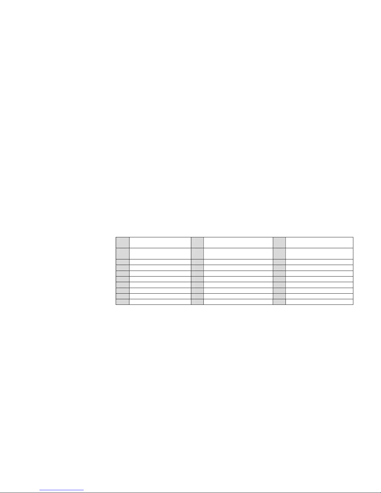
Terminals:
(n.o. =normally
open contact,
n.c. =normally
closed contact,
c.o. =changeover
contact)
Terminals: Plug-in terminals on the back panel
Weight: 304g
Hardware: 2 quick-mounting clips
1 operating instructions
Warranty: 2 years
Other options: – special measuring range / signal output
– customer functions, OEM customer home screen / logo
– Transparent cover IP55
1 Pt100 sense - 11 contact 2 n/c 21 + current signal or voltage
signal input
2 Pt100 - 12 contact 2 c/o 22 - (Gnd) current signal or
voltage signal input
3 Pt100 + 13 PE supply 23 contact 3 n/o*
4 PE Pt100/ current output 14 N supply 24 contact 3 n/c*
5 Signal current output + 15 L1 supply 25 contact 3 c/o*
6 Signal current output - 16 contact 5 n/o 26 contact 4 n/o*
7 contact 1 n/o 17 contact 5 n/c 27 contact 4 n/c*
8 contact 1 n/c 18 contact 5 c/o 28 contact 4 c/o*
9 contact 1 c/o 19 do not use
10 contact 2 n/o 20 sensor supply 20VDC
*optionally available
 Loading...