

Mosel Vitelic MSSI241, MSSI241B Datasheet
MOSEL VITELIC
1
PID224B 04/95
MSSI121/241/241B
INSTANT VOICE ROM
Features
Single power supply can operate at 2.4V
through 6V.
Current output can drive 8 ohm speaker with a
transistor, Vout can drive buzzer directly.
The voice content is stored for 7-12 seconds for
SI121 ( 13-24 for SI241/241B ) including mute
and is single section / phrase and single trigger.
Automatic power down.
A phrase is composed of repetitive sections.
Interrupt function (INTP) stops the audio output
at once.
An LED function with 3Hz flash is provided to
tell the audio status.
Repeat pin was provided to keep audio output
repeating.
Built-in power on play function and is
programmable.
Programmable option for either Retrigger or not.
Programmable option for either Level or Edge
trigger type.
Programmable option for either Holdable or
Unholdable output type.
Programmable option for repeat times up to 8
times.
Programmable option for either LED display or
STOP pulse on LED/STP pin.
SI121 can be programmed by MSM9159,
MSM9156, MSM9140 & MSM9139.
SI241/241B can be programmed by MSM9159,
MSM9140.
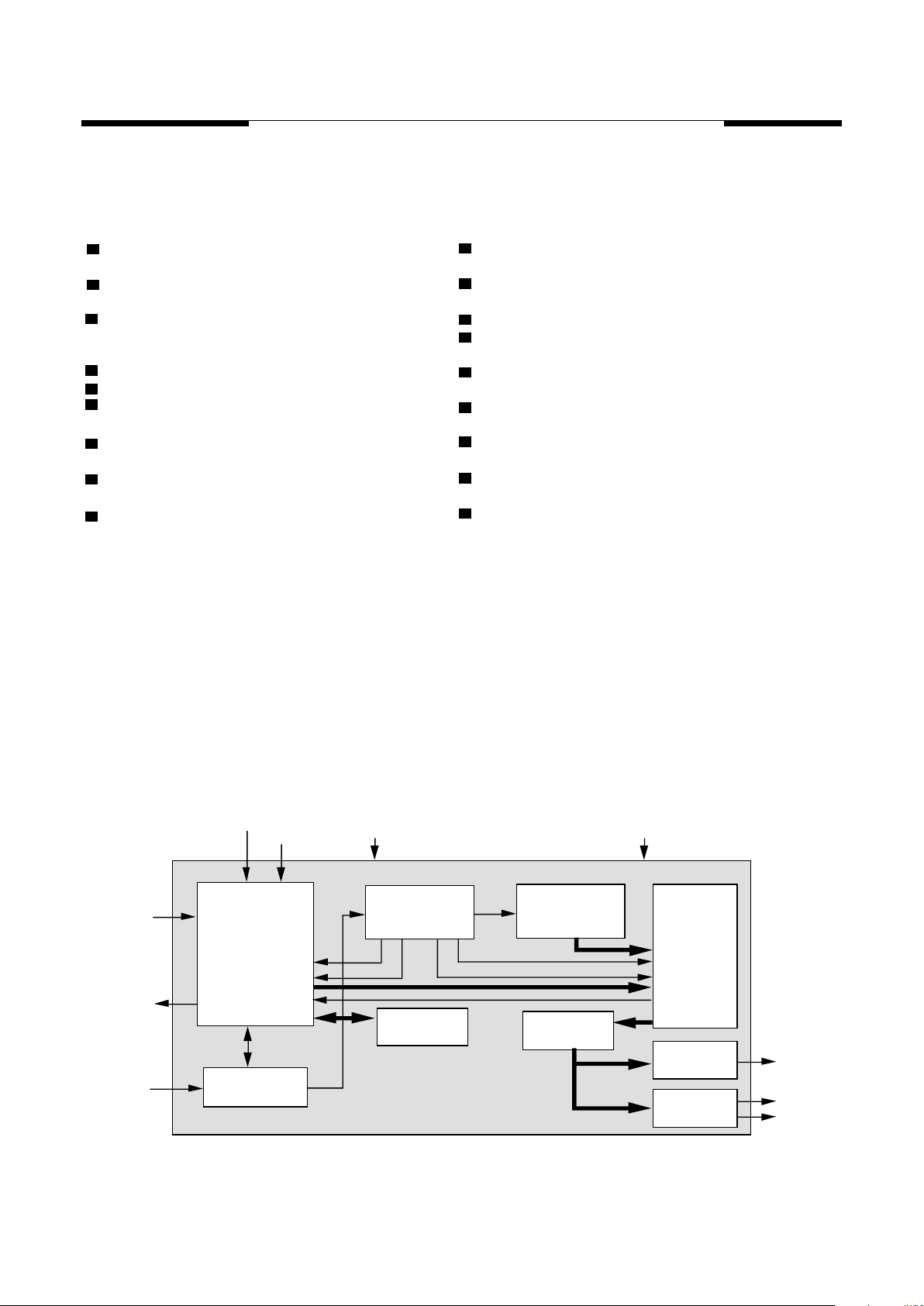
Block Diagram
CLOCK
GENERATOR
CONTROL
LOGIC
TG
INTP
REP
LED/STP
OSC
TIMING
GENERATOR
ADDRESS
GENERATOR
VOICE
ROM
TRIGGER
TABLE
MPCM
DECODER
CURRENT
BUFFER
BUZZER
BUFFER
C
OUT
V
OUT1
V
OUT2
V
DD
V
SS
A STOP pulse comes out when audio signal is
finished.
CDS input interface with 10ms debounce is
provided for trigger pin, REP pin and INTP pin.
MOSEL VITELIC
Pad Description
2
PID224B 04/95
MSSI121/241/241B
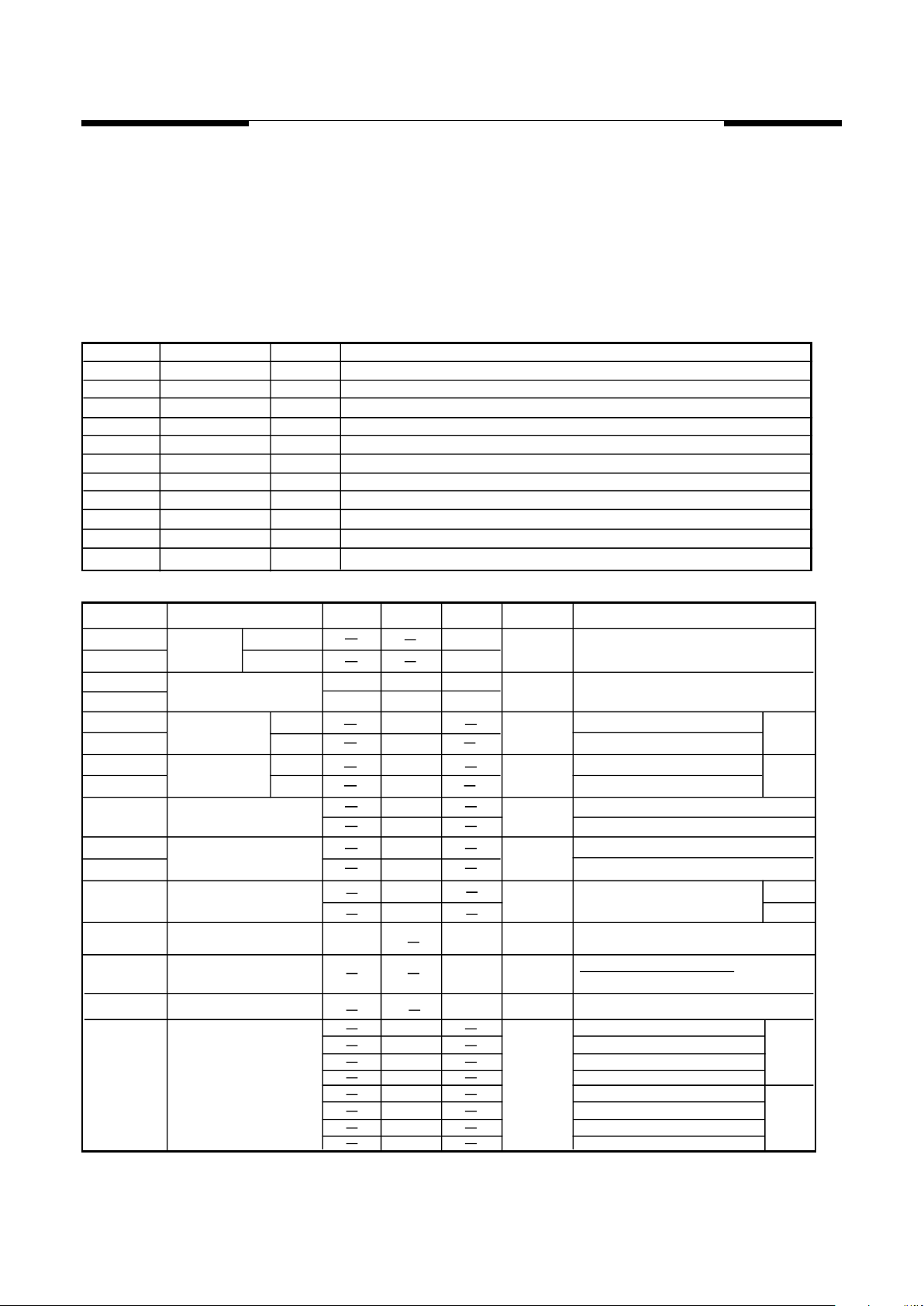
DC Characteristics
Pad No.
Signal Name Function
1
2
3
4
5
6
7
V
DD
OSC
REP
V
SS
V
OUT1
Positive power supply
Oscillator Resistor input
Negative power supply
I/O
I
O
Power
INTP
LED/STP
C
OUT
I
Power
8
9
10
V
OUT2
O
O
I
Audio signal voltage output (for buzzer)
Audio signal voltage output (for buzzer)
LED signal output / One shot stop signal output
Audio signal current output (for speaker)
Repeat pin, high active
Interrupt input, internal pull low, high active
I
O
TG Trigger input, internal pull low, high active
CLK I
Clock for programming
11
Description
The MSSI121/241/241B is an one time programmable CMOS VLSI ASIC that can memorize voice for 7-12
/ 13-24 seconds using 6-bit MOSEL qualified coding method (MPCM). Most of the necessary circuit are
built in like oscillator, ROM, DAC and interface logic. Versatile functions can be performed with minimum
external components. Customer voice data will be edited and built in by MOSEL writer in an instant time
base.
V = 3.0V, S.R. = 6KHz
Symbol Parameter Min. Max.
Typ.
Unit Condition
I
I
I
I
Supply
Current
Stand by
Operating
O/P Current
V
,V
Output Current (C )
Drive
Sink
µA
V = 4.5V, I/O Open
DD
SB
OP
OH
OL
OUT1 OUT2
-12
12
1
500
mA
mA
I
CO
DD
V = 0V
O/P
V = 4.5V,
V = 4.5V
O/P
V = 4.5V,
DD
V
V
Input Voltage
IH
IL
+0.3
V
DD
V = 4.5V
TG, INTP, REP
OUT
6
I
Output Current STP
OH -5
+5
mA
I
LED
V = 0V
O/P
V = 4.5V,
DD
V = 4.5V
O/P
V = 4.5V,
DD
V = 4.5V
DD
4
4.5
-0.3 0
I
OL
Output Current LED
0
12
mA
V =4.5V, V -V =2V
DD
DD O/P
depend on programmed data
%
Input Leakage current
10
µA
V = 4.5V
DD
DD
V = 4.5V, R
OSC
= 1.2MΩ
∆
F/F Fosc Variation
10
∆F/F
Frequency Stability
5
%
F
OSC
(4.5V) - F
OSC
(4V)
F
OSC
(4.5V)
I
LK
5
I
I
O/P Current
V
,V
Drive
Sink
OH
OL
OUT1 OUT2
-11
11
mA
DD
V = 0V
O/P
V = 4.5V,
V = 4.5V
O/P
V = 4.5V,
DD
V = 3.0VDD , Full scale
, Full scale
I241
I241B
I241B
I241
4
7.5
°”
°”
1100
770
1200
850
DD
V = 3.0V, S.R. = 8KHz
DD
V = 4.5V, S.R. = 6KHzDD
V = 4.5V, S.R. = 8KHzDD
KΩ
R1
Oscillation Resistor
V = 3.0V, S.R. = 6KHz
910
660
970
700
DD
V = 3.0V, S.R. = 8KHz
DD
V = 4.5V, S.R. = 6KHzDD
V = 4.5V, S.R. = 8KHzDD
I241B
I121
I241
 Loading...