

Mosel Vitelic MSS4305, MSS6605, MSS3205, MSS2105 Datasheet
d
d
r
MOSEL VITELIC INC.
preliminary
MSS2105/S3205/S4305/S6605
August 1996
Features
Single power can operate at 2.4V through 6.0V.
Current output could drive 8 ohm speaker with a
transistor, Vout could drive buzzer directly.
The voice content is stored up to 60 seconds at
5.8 KHz (55500h) for S6605 and can be separated to
128 sections. See next page for other device's data.
Duration of each section can be different and is
multiples of 100h.
Total duration of all 128 sections with mute is up
to 96 seconds (80000h).
The voice content can be accessed in "Sentence"
type on KeyBoard (KBD) and Matrix(MTX) modes.
Up to 50 Sentences for KeyBoard, 56
Sentences for Matrix modes.
Each sentence is composed of one or more than
one section(s).
Automatic power down .
Three addressing interface modes are provided for
versatile applications: CPU, KBD and MTX.
KeyBoard addressing mode:
a. 50 sentences can be accessed by 15
addressing input dual-tree type trigger.
b. Sentence is numbered by 00 through 49.
c. 5 input pins on D-tree (D0-D4) tells the 1st digit
(0 through 4), another 10 input pins on S-tree
(S0-S9) tells the 2nd digit (0 through 9). By these
two digits,all 50 sentences can be accessed.
d. With 2nd digit only also can access a sentence.
e. Section is located and numbered by 0 through 127.
f. Total section number of all sentences is up to 256.
21"/32"/43"/60 " VOICE ROM
Matrix addressing mode:
a. 56 sentences can be accessed by 8x7
wiring matrix.
b. Sentence is numbered by 00 through 55.
c. Section is located and numbered by 0 through
127.
d. Total section number of all sentences is up to
256.
CPU addressing mode:
a. 128 sections can be accessed by 7 address bits
with an enable strobe trigger.
b. Section is located and numbered by 00 through
127 .
Power on trigger play is available by bonding V
trigger together.
A dedicate LED output pin with 6 Hz flash is
provided to tell the audio status.
Playall function (OKY) plays all up to 64 define
sentences one by one by single trigger.
Playnext (sequential) function (OKY) : one trigger
plays next sentence of up to 64 define
sentences circularly.
Random-play function (OKY) : one trigger plays one
of 64 defined sentences randomly.
Continue sequence(PLAYNEXT):The first OKY trigger
after any addressing will keep current sequence
continuously.
Home sequence(PLAYNEXT):The first OKY trigge
after any addressing will return the sequence to the
first sentence.
Automatically ramp up & ramp down.
Sound Sentence & quality could be emulated on 9009
board.
SS
and
Specifications subject to change without notice, contact your sales representatives for the most recent information.
1/27
PID248*** 08/96
MOSEL VITELIC INC.
preliminary
MSS2105/S3205/S4305/S6605
Description
The MSS6605 is a single-chip CMOS VLSI ROM that can memorize voice up to 60 seconds using
MOSEL qualified coding method (MPCM) at 5.8 KHz.
Three addressing interfaces are provided: CPU mode, KEYBOARD mode and MATRIX mode for versatile
applications. The voice content can be stored separately into 128 sections or 50 or 56 sentences with
arbitrary length. With minimum external components, this chip can be applied to various application.
Customer voice data will be edited and programmed into ROM by changing one mask during fabrication.
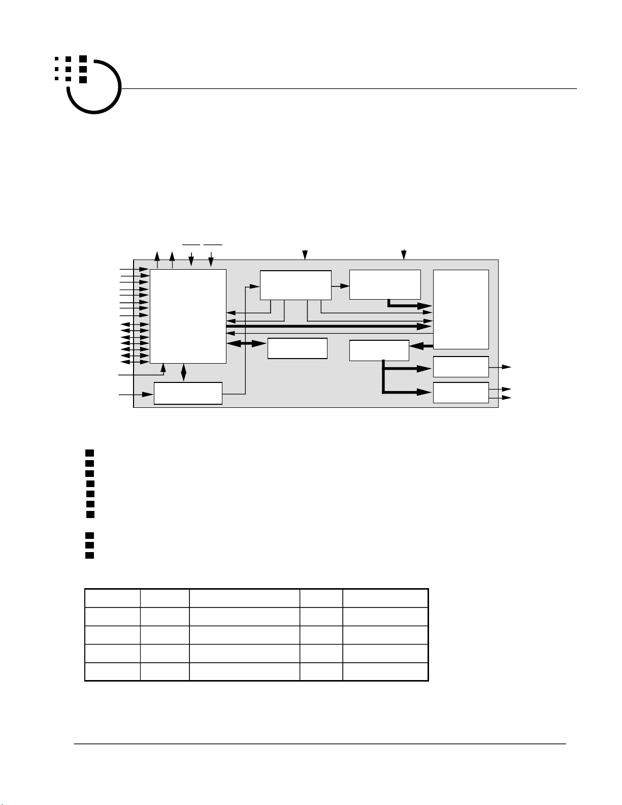
Block Diagram
BS
TG0
TG1
TG2
TG3
TG4
TG5
TG6
TG7
ROW0
ROW1
ROW2
ROW3
ROW4
ROW5
ROW6
CHG
OSC
GENERATOR
INTP OKYLED
CONTROL
LOGIC
CLOCK
V
DD
TIMING
GENERATOR
TRIGGER
TABLE
ADDRESS
GENERATOR
DECODER
MPCM
V
SS
VOICE
ROM
SPEAKER
BUFFER
BUZZER
BUFFER
Mask option for
either Level or Edge trigger type for MTX and KBD addressing modes.
either Holdable or unholdable output type for MTX and KBD addressing modes.
either retriggerable or not for all 3 addressing modes.
either BUSY signal or STOP pulse output on BS output.
either low or high active for STOP pulse output.
random or playall or playnext (sequential ) output on OKY (one key) input pin.
either return to the 1st section(ORIGINAL)or keep continuing (CURRENT) for PLAYNEXT (sequential)
function.
3 addressing interface modes.
either slow (20ms) or regular (5ms) debounce time for MTX & KBD addressing mode.
either long (80ms) or regular (40ms) stop pulse width.
C
V
V
OUT
OUT1
OUT2
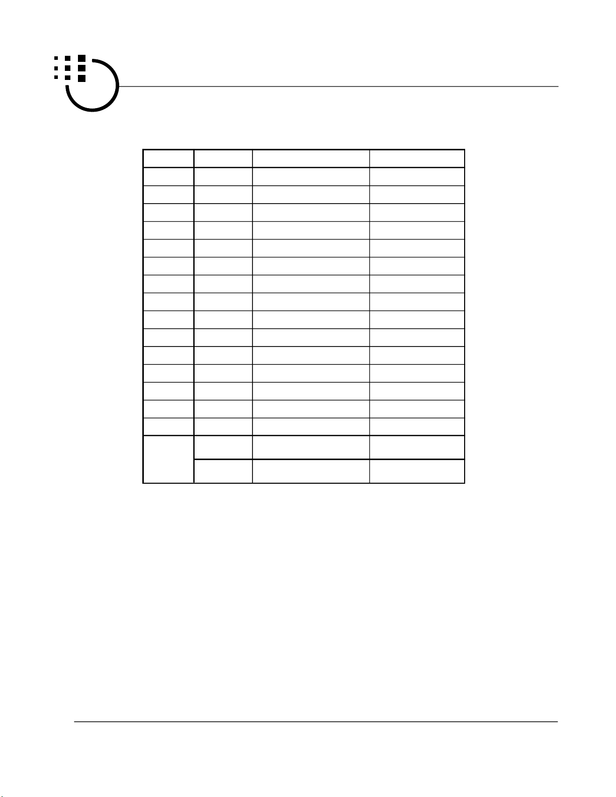
Voice Storage Reference
Device
MSS6605
MSS4305
MSS3205
MSS2105
Specifications subject to change without notice, contact your sales representatives for the most recent information.
Capacity
55500h
40000h
30000h
20000h
Duration at 6 KHz S.R.
58.2 seconds
43.6 seconds
32.7 seconds
21.7 seconds
Section
128
128
128
128
2/27
Entry/Sentence
256/64
256/64
256/64
256/64
PID248*** 08/96
MOSEL VITELIC INC.
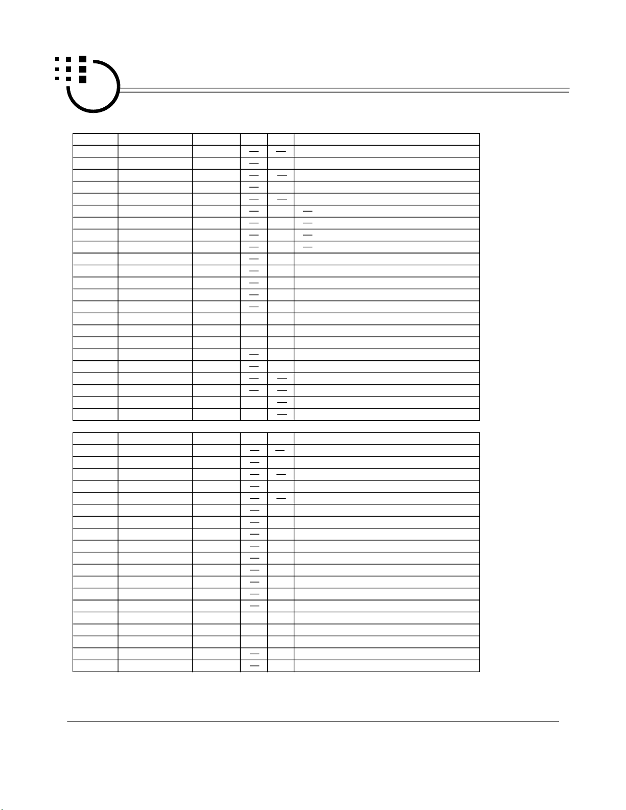
Pad Description
Pad No.
21~28
1~7
8
9
10
11
16
12
13
13
14
15,17
18
19
20
NC: No connection
Signal Name Function
~
TG7
ROW6~ROW0
INTP I
OKY
LED
CHG
NC
C
OUT
V
DD
ROSC
V
SS
V
OUT2
V
OUT1
BS
TG0
I/O
I
NC/I/O
I
O
I
NC
O
Power
I
Power
O
O
O
preliminary
Active
L
L
MSS2105/S3205/S4305/S6605
CPU mode: address input (TG0 ~ TG6), internal pull
high, negative strobe trigger (TG7).
KBD mode: with ROW0 ~ROW6 for trigger input,
internal pull high, active low.
MTX mode: with ROW0 ~ROW6 for scanning function,
internal pull high, active low.
CPU mode: No connection.
KBD mode: with TG0 ~ TG7 for trigger input,
internal pull high, active low.
ROW0~ROW4 are used as Decimal digit (D-tree)
ROW5 and ROW6 are used for S-tree.
MTX mode: with TG0 ~ TG7 for scanning function,
used as output pins.
Interrupt, stops the audio output at once;low active.
One key Play, playall or playnext or random-play;active low.
LED, sink current
Change addressing interface mode from existing mode
Audio signal current output (for speaker)
Positive power supply
Oscillator Resistor input
Negative power supply
Audio signal voltage output (for buzzer)
Busy / Stop
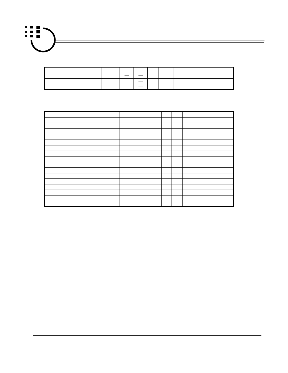
Absolute Maximum Rating
Symbol
V - V
T (Operating)
T (Storage)
Specifications subject to change without notice, contact your sales representatives for the most recent information.
DD
V
V
OUT
SS
IN
Name
DC supply voltage
Input voltage
Output voltage
Operating Temperature
Storage Temperature
Rating
-0.5 ~ +7.0
V - 0.3 ~ V + 0.3
SS
DD
V ~ V
SS
-10 ~ +60
-55 ~ +125
DD
Unit
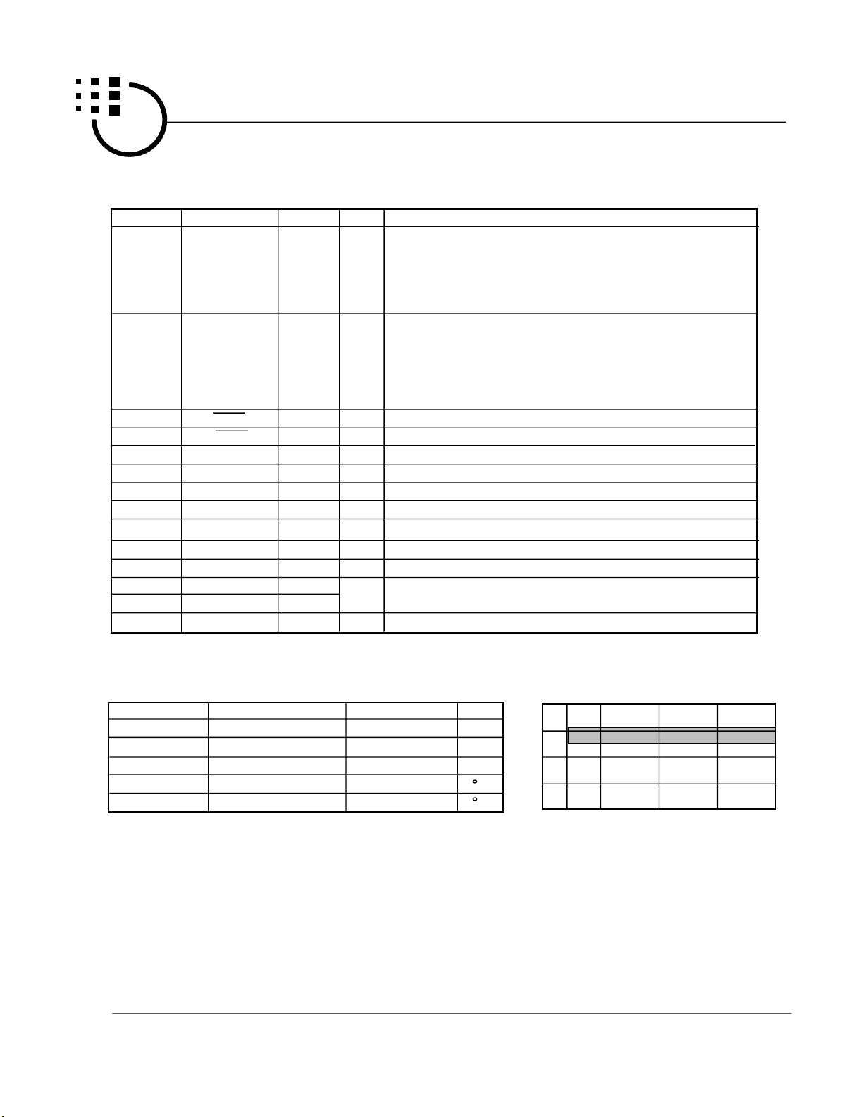
F
8000
V
6000
V
4000
2000
C
Hz
C
3/27
OSC
Characteristics
Max
Min
2.4
2.0 3.0 4.0 5.0 6.0
S.R.=6000Hz
PID248*** 08/96
6400
5000
VDD

MOSEL VITELIC INC.
y
d
y
d
e
x
r
preliminary
MSS2105/S3205/S4305/S6605
Signals
Cout
This pin can drive speaker through a transistor.
Cout is tristate during standby.
Cout has zero current output when sound data is
zero. Cout has full current output when sound
data is the highest. Cout has half of full current
output when sound is silence at middle data value.
Cout has half of full current output when playing
sound at appended memory-less mute.
The bypass Cout Resistor is used to bypass the
audio output current from Cout. This bypassing
extra current to ground gives a way to prevent the
saturation of audio waveform amplified b
transistor. This Resistance is 470 ohm typically. It
always is not very small. Or user can let it open if
the transistor has a fair beta value.
A transistor with beta value 150 is sufficient for
typical applications. Larger beta value get larger
sound but may have the amplified waveform
saturated.
8 ohm speaker is recommended. The speaker
characeristics and housing impacts the loudness
very much.
Vout1, Vout2
They are tristate during standby state.
These two pins can drive buzzer directly. The
piezo buzzer used should have its resonant
frequency at the center of your sound frequency
domain or you are unable to play your sound good
by this buzzer.
For instance, you have your sound spans over
frequency from 100 Hz through 1 KHz. A buzzer
with resonant frequency at 300 Hz will play this
sound good. A buzzer with resonant frequency at
1 KHz will distort the sound very much because
that most of the energy of the playback sound is
unable to be played by this buzzer.
TG0, TG1, TG2, TG3, TG4, TG5, TG6
These 7 pins have 4 ways to perform.
The lst way (KBD addressing 1):
When user defines less than 11 sentences, a Vss
pulse wider than t T applied to TG0 plays sentence
2, TG1 plays sentence 3,..., TG6 plays sectence 8.
Of course, the fabrication should be masked as
Keyboard addressing.
The 2nd way (KBD addressing 2):
When user defines more than 10 sentences, he
can access the first ten sentences by way 1st. To
access the 11st sentence or higher, these 7 pins
are played as the S-tree. TG6 means 8, TG5
means 7, ..., TG0 means 2. Of course, the
fabrication should be masked as Keyboar
addressing.
The 3rd way (Matrix addressing ):
To coorperate with TG7 as well as 7 ROWn pins
Specifications subject to change without notice, contact your sales representatives for the most recent information.
(ROW0 through ROW6), they form an 8x7 matrix
in 56 cross points. The touch of a cross point
activates a trigger signal to play repectivel
sentence. Of course, the fabrication should be
masked as matrix addressing.
The 4th way (CPU addressing):
They are 7-bit high-true addresses to specify the
section to be played among 128. TG6 is the MSB
while TG0 is the LSB. They should meet the
address hold time required, t H. Of course, the
fabrication should be masked as cpu addressing.
TG7
This pin has 4 ways to perform.
The 1st way (KBD addressing 1):
When user defines less than 11 sentences, a Vss
pulse wider than t T applied to TG7 plays sentence
9. Of course, the fabrication should be masked as
Keyboard addressing.
The 2nd way (KBD addressing 2):
When user defines more than 10 sentences, he
can access the first ten sentences by way 1st. To
access the 11st sentence or higher, this TG7
means number 9 of S-tree. Of course, the
fabrication should be masked as Keyboar
addressing.
The 3rd way (Matrix addressing ):
To coorperate with 7 TGn pins (TG0 through TG6)
as well as 7 ROWn pins (ROW0 through ROW6),
they form an 8x7 matrix in 56 cross points. The
touch of a cross point activates a trigger signal to
play repectively sentence. Of course, th
fabrication should be masked as matri
addressing.
The 4th way (CPU addressing):
Address Strobe.
Its rising edge latches the 7-bit addresses and
starts the playing. Its falling edge stops
immediately the playing sound, activates (o
keeps) the busy output to be high, activates the
audio output to stay at center value, activates the
LED output. Its width should be wide enough as t
W. Of course, the fabrication should be masked
as cpu addressing.
ROW0, 1, 2, 3, 4, 5, 6
These 7 pins have 3 ways to perform.
The 1st way (KBD addressing 1):
When user defines less than 11 sentences, a Vss
pulse wider than t T applied to ROW6 plays
sentence 1, ROW5 plays sectence 0. Of course,
the fabrication should be masked as KeyBoard
addressing.
The 2nd way (KBD addressing 2):
When user defines more than 10 sentences, of
4/27
PID248*** 08/96
MOSEL VITELIC INC.
preliminary
course he can access the first ten sentences by
way 1st. To access the 11st sentence or higher,
these 5 pins (ROW0 through ROW4) are played as
the D-tree. ROW5 and ROW6 are played as
S-tree. ROW6 means 1, ROW5 means zero.
ROW4 means 40, ROW3 means 30, ..., ROW0
means 0. Of course, the fabrication should be
masked as KeyBoard addressing.
The 3rd way (Matrix addressing):
To cooperate with TG7 as well as 7 TGn pins (TG0
through TG6), they form an 8x7 matrix in 56 cross
points. The touch of a cross point activates a
trigger signal to play respectively sentence.
Of course, the fabrication should be masked as
matrix addressing.
Rosc
This is a pin to provided bias to activate built in
VCO circuit. A 1200 K ohm resistor serial from
Vdd (3.0V) to this pin can play the audio output at
6 KHz sample rate. Larger Rosc plays lower
frequency.
LED
This is an output pin which can flash an LED lamp
at Fix 6 Hz in a sink type by I led. Fix 6 Hz flash
means this pin turns LED lamp on for 83 ms and
then turns it off for 83 ms alternately.
MSS2105/S3205/S4305/S6605
filename of
S6605's
1
S6605QA
S6605QE
2
filename of
S4305's
S4305QA
S4305QE
filename of
S3205's
S3205QA
S3205QE
filename of
S2105's
S2105QA
S2105QE
Functions
to define 128 word sections
to define 64 sentence tables
Specifications subject to change without notice, contact your sales representatives for the most recent information.
5/27
PID248*** 08/96

MOSEL VITELIC INC.
e
o
d
preliminary
MSS2105/S3205/S4305/S6605
Terms
Retrigger Trigger
Retriggerable Trigger-m means the sentence-m
addressed by Trigger-m could be retriggerred by
other Triggers. It can be retriggerred by itself.
Cycle Loop
It is determined automativally by the sentences
user defined at fabrication.
Continue OKY & Home OKY
This is a function belongs to OKY and determines
the play sequence when the first OKY comes after
any other trigger addressing. The "continue"
preserves the sequence while the "home"rewinds
to the very beginning. You will see a term
S.W.A.I. in this data sheet, it means sequence
when after interrupt by other trigger addressing.
Smaple Rate
There are some parameters are sample rat
dependent. They aare debounce time, LED fix
flash frequency and Stop pulse width. The
numbers mentioned in this data sheet are based
on 6 KHz sample rate typically, but just typical .
Smaller Rosc playback quicker - higher pixel rate.
MVI provides voice chip with very flat response for
playback vs working voltage. Higher working
voltage get slower playback but insignificantly.
Stop Pulse
Stop pulse is one of Status definition. This Stop
pulse is not guaranteed when user defines the
trigger behavior as Holdable.
Key Priority
The key priority defines which trigger is to be
acknowledged when two or more triggers are
being activated. For both KeyBoard and Matrix
addressing modes, no key priority is guaranteed.
It means when playing a sound, only one key is
promised, further triggers is not guaranteed until
when this sentence is accomplished and trigger is
released.
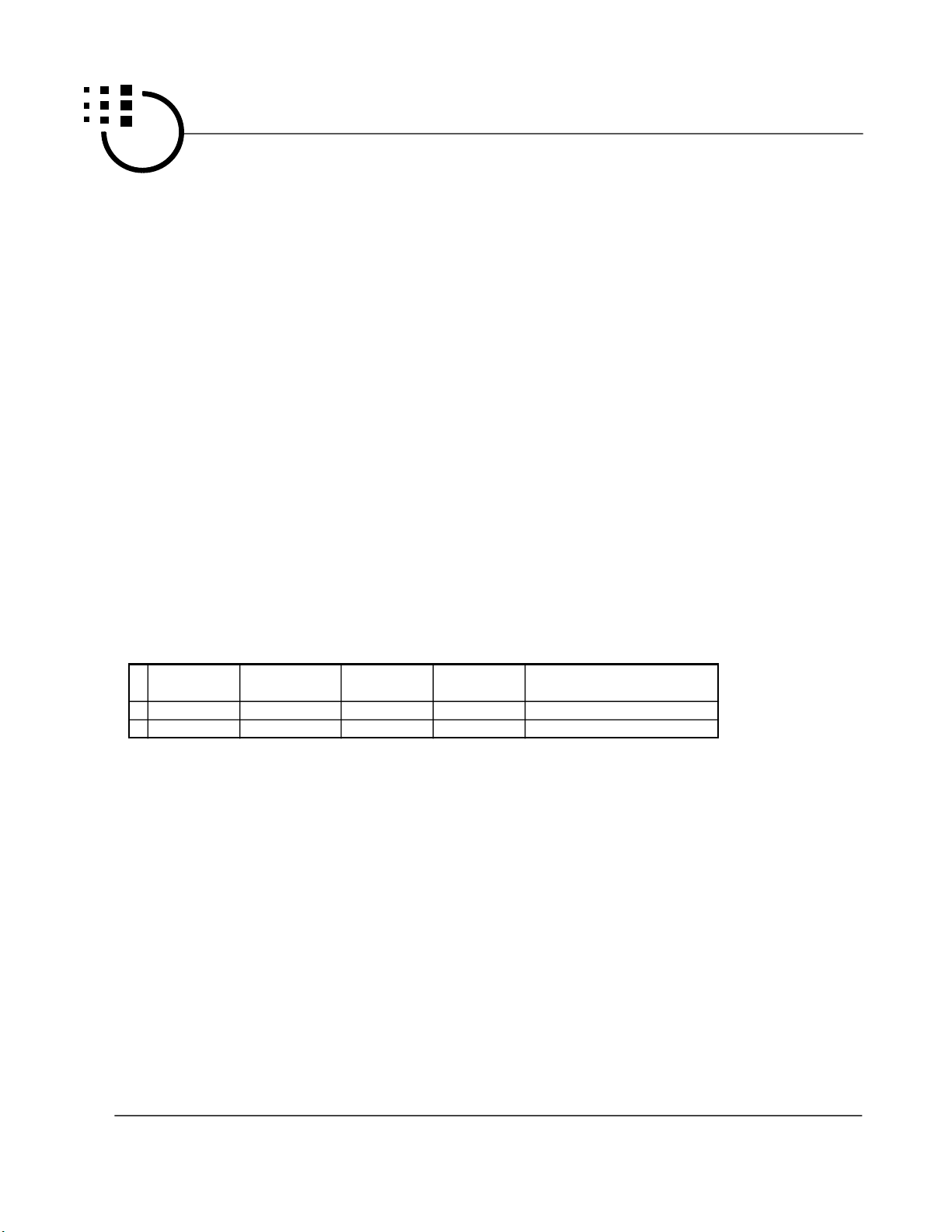
Application Notes
To play words concatenated
To play two words concatenated at cpu addressing
mode, cpu should take care during the interval in
between. When detecting the busy signal falls to
low, the next word had better to start in within t PL.
Because during this t PL interval, the Cout sounds
silent but keeps at the center of full scale. The
former word starts within t PL interval will start
smoothly without abrupt potential change on current
through speaker.
Longer than the t PL interval the Cout begins ramp
down interval, it is recommended to not start the
former word. It does not sound bad, but ramp up
starts at the ramp down interval is not preferred.
Parallel chips
Parallel chips share a speaker is not recommended
at cpu addressing mode. Please don't use this
solution. MVI offers 120" chip to replace this parallel
chips solution.
When user insists to adopt this solution due to no
alternate, the cpu should take care when playing two
words simultaneously or concatenated from tw
respective chips. As described, the silence hears
nothing on speaker but there is signal potential
appears on Cout output pin.
There are four occurances to have potential signal
on Cout but you hear nothing. With Two sources
both have any one of above occurances, the
summation will cause particular signal output and
even noice. These four occurances are (1) silence
from ramp up (2) silence from ramp down (3) silence
from at middle data value either in-between sound or
in interval t PL (4) silence form appende
memory-less mute.
To left sentence empty
User may not define every sentence. But every
sentence accessed by OKY must be defined, cannot
be empty. This kind of mis-use always happens
when customer define several not concatenated
sentences under matrix addressing mode. At this
time, OKY is not allowed to access or the error may
occur due to there is empty sentence.
Specifications subject to change without notice, contact your sales representatives for the most recent information.
6/27
PID248*** 08/96
MOSEL VITELIC INC.
Addressing Reference
preliminary
MSS2105/S3205/S4305/S6605
TG7
TG6
TG5
TG4
TG3
TG2
TG1
TG0
ROW6
ROW5
ROW4
ROW3
ROW2
ROW1
ROW0
To play
KeyBoard
S=9
S=8
S=7
S=6
S=5
S=4
S=3
S=2
S=1
S=0
D=40
D=30
D=20
D=10
D=0
D+S
CPU
Strobe
A6, MSB
A5
A4
A3
A2
A1
A0
X
X
X
X
X
X
X
binary (A6543210)
Matrix
T=7
T=6
T=5
T=4
T=3
T=2
T=1
T=0
R=6
R=5
R=4
R=3
R=2
R=1
R=0
8 x R + T
sentence section sentence
Specifications subject to change without notice, contact your sales representatives for the most recent information.
7/27
PID248*** 08/96
MOSEL VITELIC INC.
preliminary
DC Characteristics at 3.0 Vdd (S6605)
MSS2105/S3205/S4305/S6605
Symbol
I sb
I op
I iht
I iLT
I ihr
I iLr
I ohr
I oLr
I ohbs
I oLbs
I led
I ohv
I oLv
I co
V co
V ohv
V oLv
R 1
R 1
R cds
R cnt
d F/F
d F/F
Parameter
Standby I
Operation I
input high I
input low I
input high I
input low I
output high I
output low I
output high I
output low V
LED sink I
output high I
output low I
current o/p V
current o/p V
output high V
output low V
Oscillation R
Oscillation R
cds R
Switch contact R
Frq. stability
Frq. variation
Valid
Vdd
Vdd
TG0-7
TG0-7
ROW0-6
ROW0-6
ROW0-6
ROW0-6
BS
BS
LED
Vout1,2
Vout1,2
Cout
Cout
Vout1
Vout2
Rosc
Rosc
Min.
-5
-10
Typ.
100
5
5
-5
5
-3.5
3.5
9
-6
+6
-2.5
1.1
840
Max.
1
300
1
1
-7
+7
80
20
5
10
Min.
Symbol
I sb
I op
I iht
I iLT
I ihr
I iLr
I ohr
I oLr
I ohbs
I oLbs
I led
I ohv
I oLv
I co
V co
V ohv
V oLv
R 1
R 1
Specifications subject to change without notice, contact your sales representatives for the most recent information.
Parameter
Standby I
Operation I
input high I
input low I
input high I
input low I
output high I
output low I
output high I
output low V
LED sink I
output high I
output low I
current o/p V
current o/p V
output high V
output low V
Oscillation R
Oscillation R
Valid
Vdd
Vdd
TG0-7
TG0-7
ROW0-6
ROW0-6
ROW0-6
ROW0-6
BS
BS
LED
Vout1,2
Vout1,2
Cout
Cout
Vout1
Vout2
Rosc
Rosc
Typ.
150
10
10
-10
10
-8
8
10
-13
+13
-3.5
1.2
860
8/27
PID248*** 08/96
MOSEL VITELIC INC.
preliminary
MSS2105/S3205/S4305/S6605
R cds
R cnt
d F/F
d F/F
cds R
Switch contact R
Frq. stability
Frq. variation
-5
-10
40
20
5
10
AC Characteristics at 4.5 V & 6000 Hz S.R.
Symbol
t T
t H
t W
t WA
t BS
t TB
t PL
t RMU
t RMD
t STP
t SET
t WLR
t WLB
t WLA
t P
t R
SRD:=Sample rate dependent; MO:=Mask optonal
Description
Trigger pulse width
Trigger address hold time
Write enable pulse width
TG7 rise to audio start
Lag between busy & stop
Lag between trig & busy
plain width behind sound
Ramp up width
Ramp down width
Stop pulse width
address set up time
write fall to ramp up start
write fall to busy start
write fall to audio stop
Power rise up time
Power ripple width
Valid
MTX, KB
CPU
CPU
CPU
CPU, MTX, KB
MTX, KB
CPU, MTX, KB
CPU, MTX, KB
CPU, MTX, KB
CPU, MTX, KB
CPU
CPU
CPU
CPU
Vdd
Vdd
Min.
21
80
40
40
0
Kohm
Kohm
%
%
Typ.
500
0
20
40
20
20
80
0
0
[ F(4.5V)-F(4.0V)] /F(4.5V)
lot by lot
Max.
Unit
Remarks
ms
SRD & MO
ns
SRD
us
SRD
us
SRD
ms
SRD
ms
SRD
ms
SRD
ms
SRD
ms
SRD
ms
SRD & MO
us
SRD
us
SRD
us
SRD
us
SRD
1
ms
1
ms
Standard Code Line Up
To be Available Soon
Specifications subject to change without notice, contact your sales representatives for the most recent information.
9/27
PID248*** 08/96
 Loading...