


Moseley Associates EVENT5800 User Manual
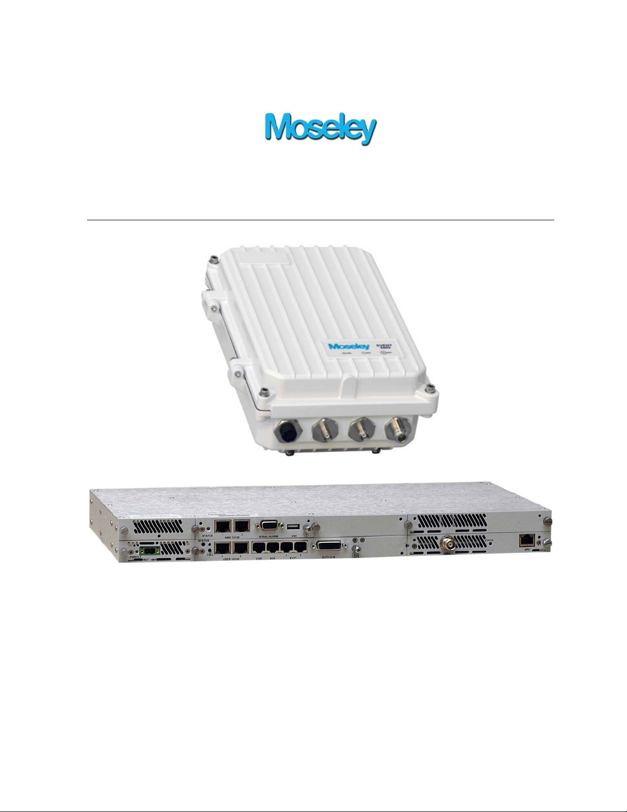
Event 5800
Installation & Reference Manual
Document Number: 602-16620-01, Rev. A
May 8, 2012

Event 5800 Installation & Reference Manual ii
© 2012 Moseley, Inc. All Rights Reserved.
This book and the information contained herein is the proprietary and confidential
information of Moseley, Inc. that is provided by Moseley
exclusively for evaluating the
purchase of Moseley, Inc. technology and is protected by copyright and trade secret
laws.
No part of this document may be disclosed, reproduced, or transmitted in any form or by
any means, electronic or mechanical, for any purpose without the express written
permission of Moseley, Inc.
For permissions, contact Moseley Marketing Group at 1-805-968-9621 or 1-805-6859638 (FAX).
Notice of Disclaimer: The information and specifications provided in this document are
subject to change without notice. Moseley, Inc. reserves the right to make changes in
design or components as progress in engineering and manufacturing may warrant.
The Warranty(s) that accompany Moseley products are set forth in the sales
agreement/contract between Moseley and its customer. Please consult the sales
agreement for the terms and conditions of the Warranty(s) provided by Moseley. To
obtain a copy of the Warranty(s), contact you Moseley Sales Representative at 1-805968-9621 or 1-805-685-9638 (FAX).
The information provided in this document is provided “as is” wit hout warranty of any
kind, either expressed or implied, including, but not limited to, the implied warranties of
merchantability, fitness for a particular purpose, or non-infringement. Some jurisdictions
do not allow the exclusion of implied warranties, so the above exclusion may not apply to
you.
In no event shall Moseley, Inc. be liable for any damages whatsoever – includ ing special,
indirect, consequential or incidental damages or damages for loss of profits, revenue,
use, or data whether brought in contract or tort, arising out of or connected with any
Moseley, Inc., document or the use, reliance upon or performance of any material
contained in or accessed from this document. Moseley’s license agreement may be
provided upon request. Additional Terms and Conditions will be finalized upon negot iat ion
or a purchase.
The above information shall not be constructed to imply any additional warranties for
Moseley, Inc. equipment including, but not limited to, warranties of merchantability or
fitness for an intended use.
Trademark Information
TM
Java
is a trademark of Sun Microsystems Inc.
Windows® is a registered trademark of Microsoft Corporation
All other brand or product names are trademarks or registered trademarks of their
respective companies or organizations.
© 2012 Moseley, Inc. All Rights Reserved. 602-16620-01, Rev. A

Event 5800 Installation & Reference Manual iii
EVENT 5800 Installation & Reference Manual
Document Number: 602-16620-01
Revision Levels:
SECTION DWG REV REVISED/RELEASED
All All A December 2011
N/A N/A B May 2012
© 2012 Moseley, Inc. All Rights Reserved. 602-16620-01, Rev. A

Event 5800 Installation & Reference Manual iv
© 2012 Moseley, Inc. All Rights Reserved. 602-16620-01, Rev. A

Event 5800 Installation & Reference Manual v
Table of Contents
1. Safety Precautions ..................................................................................... 1-1
1.1 RF Energy Health Hazard ............................................................................. 1-1
1.2 Protection from Lightning ............................................................................. 1-1
1.3 Protection from RF Burns ............................................................................. 1-1
1.4 Risk of Personal Injury from Fiber Optics ........................................................ 1-1
1.5 This is a Class A product .............................................................................. 1-1
1.6 Turn off all power before servicing ................................................................ 1-1
1.7 Power Supply Safety Requirements ............................................................... 1-2
1.8 Battery must be replaced correctly ................................................................ 1-2
1.9 Proper Disposal .......................................................................................... 1-2
1.10 Equipment RF Protection ............................................................................ 1-2
1.11 Regulatory Notices .................................................................................... 1-3
2. System Description .................................................................................... 2-1
2.1 Introduction ............................................................................................... 2-1
2.1.1 Example Applications ............................................................................. 2-1
2.1.2 Operational Overview ............................................................................ 2-1
2.2 System Features ........................................................................................ 2-3
2.3 Physical Description .................................................................................... 2-4
2.3.1 Model Types ................................................. Error! Bookmark not defined.
2.3.2 Back Panel ........................................................................................... 2-4
2.3.3 Hardware Modules ................................................................................. 2-4
2.3.4 Back Panel Connectors ........................................................................... 2-6
2.3.4.1 Power Supply Module Connector ........................................................ 2-6
2.3.4.2 Controller Module Connectors ............................................................ 2-6
2.3.4.3 Standard Master I/O Module Connectors ............................................. 2-7
2.3.4.4 GigE Master I/O Module Connectors ................................................... 2-7
2.3.4.5 42xE1/T1 Master I/O Module Connectors ............................................ 2-7
2.3.4.6 ASI Mini I/O Module Connectors ......................................................... 2-8
2.3.4.7 Optional OC-3 Mini I/O Module Connectors .......................................... 2-8
2.3.4.8 Optional STM-1 Mini I/O Module Connectors ........................................ 2-8
2.3.5 LEDs ................................................................................................... 2-8
2.3.5.1 Back Panel LEDs .............................................................................. 2-8
2.3.6 External AC to DC Converter .................................................................. 2-10
2.4 Block Diagram & Functional Components ...................................................... 2-10
2.5 Consecutive Point Architecture .................................................................... 2-12
2.6 Spanning Tree Protocol (STP) ...................................................................... 2-14
2.7 1+1 Protection .......................................................................................... 2-14
2.7.1 Protected Non-Diversity (Hot Standby) .................................................... 2-14
2.7.2 Protected Diversity ............................................................................... 2-15
2.7.2.1 Frequency Diversity ........................................................................ 2-15
2.7.2.2 Spatial Diversity ............................................................................. 2-15
2.8 1+1 Multi-Hop Repeater Configuration .......................................................... 2-15
2.9 Data Interfaces ......................................................................................... 2-17
2.10 100 Mbps Fast Ethernet ............................................................................ 2-17
2.10.1 155Mbps Fast Ethernet ........................................................................ 2-17
2.10.2 Two Network Operation ....................................................................... 2-17
2.10.3 Single Network Operation .................................................................... 2-17
2.11 Gigabit Ethernet (1000 Mbps) .................................................................... 2-17
2.11.1 GigE Port Based VLAN ......................................................................... 2-18
2.12 Ethernet Quality of Service (QoS) ............................................................... 2-18
© 2012 Moseley, Inc. All Rights Reserved. 602-16620-01, Rev. A

Event 5800 Installation & Reference Manual vi
2.13 Gigabit Ethernet Link Aggregation Configuration ........................................... 2-19
2.13.1 2+0 East/East Configuration ................................................................ 2-19
2.13.2 4+0 East/East Configuration ................................................................ 2-19
2.14 Crosspoint Switch .................................................................................... 2-20
2.15 STM-1 Specifications ................................................................................ 2-21
2.16 STM-1 Mux/Demux (Optional) ................................................................... 2-21
2.17 Power Management .................................................................................. 2-21
2.18 Network Management ............................................................................... 2-22
2.18.1 IP Address ......................................................................................... 2-22
2.18.2 Network ............................................................................................ 2-23
2.18.3 NMS Network Operational Principles ...................................................... 2-23
2.18.4 Third Party NMS Support ..................................................................... 2-24
2.19 System Loopbacks ................................................................................... 2-24
3. Pre-Installation Procedures ....................................................................... 3-1
3.1 Site Evaluation ........................................................................................... 3-1
3.2 Critical System Calculations ......................................................................... 3-3
3.2.1 Received Signal Level (RSL) and Link Budget ............................................ 3-3
3.2.2 Fade Margin Calculation ......................................................................... 3-4
3.2.3 Availability Calculation ........................................................................... 3-4
3.3 Frequency Plan Determination ...................................................................... 3-5
3.4 Facility Requirements .................................................................................. 3-6
3.5 Antenna Planning ....................................................................................... 3-6
3.6 Transmit Power Setup ................................................................................. 3-6
3.6.1 5.8 GHz Band ....................................................................................... 3-7
3.6.2 5.3 GHz Band ....................................................................................... 3-7
3.6.2.1 Internal Antenna ............................................................................. 3-7
3.6.2.2 External Antenna ............................................................................. 3-7
4. Installation ................................................................................................ 4-1
4.1 Unpacking ................................................................................................. 4-1
4.2 Notices ..................................................................................................... 4-1
4.3 Pre-Installation Notes .................................................................................. 4-1
4.4 Back-to-Back Bench Testing ......................................................................... 4-1
4.5 EVENT 5800 Installations ............................................................................. 4-2
4.5.1 Table Top or Cabinet Installation ............................................................. 4-3
4.5.2 Rack Installation ................................................................................... 4-3
4.5.3 External Waveguide Filter Installation ...................................................... 4-3
4.6 External Equipment Connections ................................................................... 4-3
4.6.1 Controller Module Connectors ................................................................. 4-3
4.6.2 Standard Master I/O Module Connectors ................................................... 4-4
4.6.3 GigE Master I/O Module Connectors ......................................................... 4-4
4.6.4 42xE1/T1 Master I/O Module Connectors .................................................. 4-4
4.6.5 ASI Mini I/O Module Connectors ............................................................. 4-5
4.6.6 Optional OC-3 Mini I/O Module Connectors ............................................... 4-5
4.6.7 Optional STM-1 Mini I/O Module Connectors .............................................. 4-5
4.7 Ground Connections .................................................................................... 4-5
4.8 Antenna/Feed System ................................................................................. 4-5
4.8.1 Antenna Mounting ................................................................................. 4-5
4.8.2 Transmission Line ................................................................................. 4-6
4.8.3 Environmental Seals .............................................................................. 4-6
4.8.4 Antenna & Transmission Line Testing ....................................................... 4-6
4.9 Connect the Power Source ........................................................................... 4-6
4.10 Link Alignment ......................................................................................... 4-7
© 2012 Moseley, Inc. All Rights Reserved. 602-16620-01, Rev. A

Event 5800 Installation & Reference Manual vii
4.10.1 EVENT 5800 RSL Output ....................................................................... 4-7
5. Quick Setup Guide ...................................................................................... 5-1
5.1 Quick Start Hardware Overview .................................................................... 5-1
5.1.1 Ensure coaxial Connections .................................................................... 5-1
5.1.1.1 PolyPhaser ...................................................................................... 5-1
5.2 Quick Start Software Settings ....................................................................... 5-1
5.2.1 PC Network Configuration ....................................................................... 5-1
5.2.2 Default IP Address ................................................................................. 5-2
5.2.3 Default User Name/Password .................................................................. 5-2
5.3 IP Address Configuration ............................................................................. 5-2
5.4 Link Configuration ...................................................................................... 5-3
5.5 Site Attributes ............................................................................................ 5-4
5.6 Reset to Factory Defaults ............................................................................. 5-5
5.7 Command Line Interface (CLI) Access ........................................................... 5-5
5.7.1 CLI Access via NMS Ethernet .................................................................. 5-5
5.7.2 CLI Access via Serial Port ....................................................................... 5-5
6. On-Site Service .......................................................................................... 6-1
6.1 Removing a Module .................................................................................... 6-1
6.2 Installing a Module ..................................................................................... 6-2
7. Specifications ............................................................................................. 7-1
7.1 System Specifications ................................................................................. 7-1
7.2 Ethernet Performance ................................................................................. 7-2
7.2.1 100 Base TX Ethernet Performance .......................................................... 7-2
7.2.2 Gigabit Ethernet (GigE) Performance ........................................................ 7-4
8. Connectors ................................................................................................. 8-1
8.1 DC Input (Power) Connector ........................................................................ 8-1
8.2 Ethernet 100BaseTX Payload Connector ......................................................... 8-1
8.3 Ethernet 1000BaseT Payload Connector ......................................................... 8-1
8.4 SONET Payload Connector ........................................................................... 8-2
8.5 STM-1 Payload Connector ............................................................................ 8-2
8.6 DVB/ASI, DS-3, E-3, STS-1 Payload Conne ctor ............................................... 8-2
8.7 NMS 10/100BaseTX Connector 1-2 ................................................................ 8-2
8.8 Alarm/Serial Port Connector ......................................................................... 8-3
8.9 T1/E1 Channels 1-2 Connector ..................................................................... 8-3
8.10 T1/E1 Channels 3-16 Connector .................................................................. 8-4
8.11 USB (for Future) ....................................................................................... 8-5
8.12 Data Order Wire ....................................................................................... 8-6
8.12.1 RS-422 .............................................................................................. 8-6
8.12.2 RS-232 .............................................................................................. 8-6
Appendix A. Abbreviations & Acronyms .......................................................... A-1
Appendix B. µV – dBm Conversion Chart ......................................................... B-1
Appendix C. FCC Applications Information ...................................................... C-1
Appendix D. Customer Service ........................................................................ D-1
D.1 Technical Consultation .............................................................................. D-1
D.2 Factory Service ....................................................................................... D-1
D.3 Field Repair ............................................................................................ D-2
© 2012 Moseley, Inc. All Rights Reserved. 602-16620-01, Rev. A

Event 5800 Installation & Reference Manual viii
List of Illustrations
Figure 2-1. Example Installation .......................................................................... 2-2
Figure 2-3. Transceiver Back Panel ...................................................................... 2-4
Figure 2-4. Receiver-Only Back Panel ................................................................... 2-4
Figure 2-5. EVENT 5800 Modules ......................................................................... 2-5
Figure 2-7. Back Panel LEDs ............................................................................... 2-8
Figure 2-9. EVENT 5800 Block Diagram .............................................................. 2-10
Figure 2-10. Ring Configuration ........................................................................ 2-13
Figure 2-11. Consecutive Point Network ............................................................. 2-14
Figure 2-12. 1+1 Non-Diversity Mode Protection ................................................. 2-15
Figure 2-13. 1+1 Diversity Mode Protection ........................................................ 2-15
Figure 2-15. 1+1 Multi-Hop Repeater Configuration ............................................. 2-16
Figure 2-16. Back Panel Connections for Drop/Insert Capabili ty ............................. 2-16
Figure 2-17. Two Network Operation .................................................................. 2-17
Figure 2-18. Single Network Operation ............................................................... 2-17
Figure 2-19. GigE Port Based VLAN .................................................................... 2-18
Figure 2-20. Ethernet Quality of Service (QoS) .................................................... 2-19
Figure 2-22. Crosspoint Switch ......................................................................... 2-20
Figure 2-23. Crosspoint Switch (a) Repeater and (b) Add/Drop Examples ................ 2-20
Figure 2-24. STM-1 Mux/Demux ........................................................................ 2-21
Figure 2-25. PC/EVENT 5800 on Same Subnet .................................................... 2-23
Figure 2-26. DTVLINKs on Different Subnets ....................................................... 2-24
Figure 3-1. 5.8 GHz Frequency Plan ..................................................................... 3-5
Figure 4-1. Back-to-Back Testing Configuration ..................................................... 4-2
Figure 4-5. DC Power Cable Connector ................................................................. 4-7
Figure 4-7. RSSI Output vs. Received Signal ......................................................... 4-8
Figure 5-2. IP Address Label Location .................................................................. 5-2
Figure 6-1. EVENT 5800 Modules ......................................................................... 6-1
Figure 6-2. Thumbscrew and Corner Screw Locations ............................................. 6-1
Figure 6-3. Threaded Hole Locations .................................................................... 6-2
Figure 6-4. Guides for Installing Cards ................................................................. 6-2
© 2012 Moseley, Inc. All Rights Reserved. 602-16620-01, Rev. A

Event 5800 Installation & Reference Manual ix
List of Tables
Table 2-1. Key Benefits/Advantages .................................................................... 2-2
Table 2-2. Master I/O Modules ............................................................................ 2-5
Table 2-3. Supported E1/T1 Combinations ............................................................ 2-5
Table 2-4. Modem Status LED ............................................................................. 2-9
Table 2-5. DVB-ASI In Status LED ....................................................................... 2-9
Table 2-6. DVB-ASI Out Status LED ..................................................................... 2-9
Table 2-7. TCM/Convolutional Code Rates ........................................................... 2-11
Table 2-8. GigE Ethernet Throughput Examples by Modulation & Bandwidth ............ 2-18
Table 3-1. Maximum IDU/ODU Cable Lengths ....................................................... 3-3
Table 3-2. Maximum Output Power vs. Modulation Order for EVENT 5800 ................. 3-6
Table 3-3. Maximum Power Settings for 5.3GHz U-NII Band Operation (US) .............. 3-8
Table 5-1. Default User Names & Passwords ......................................................... 5-2
Table 5-2. Serial Cable Pinout ............................................................................. 5-5
Table 5-3. Serial Port Parameters ........................................................................ 5-5
Table 7-1. 100 Base TX Ethernet % Nominal Throughput ........................................ 7-3
Table 7-2. 100 Base TX Ethernet Latency (msec) ................................................... 7-3
Table 7-3. Gigabit Ethernet % Nominal Throughput ............................................... 7-4
Table 7-4. Gigabit Ethernet Latency (msec) .......................................................... 7-4
© 2012 Moseley, Inc. All Rights Reserved. 602-16620-01, Rev. A

Event 5800 Installation & Reference Manual x
© 2012 Moseley, Inc. All Rights Reserved. 602-16620-01, Rev. A

1. Safety Precautions 1-1
1. Safety Precautions
PLEASE READ THESE SAFETY PRECAUTIONS!
Do not turn on power before reading Moseley’s product documentation. This device has a
-48V DC direct current input.
1.1 RF Energy Health Hazard
This symbol indicates a risk of personal injury due to radio frequency
exposure.
The radio equipment described in this guide uses radio frequency transmitters.
Although the power level is low, the concentrated energy from a directional
antenna may pose a health hazard. Do not allow people to come in close proximity to the
front of the antenna while the transmitt er is operating. The antenna will be professionally
installed on fixed-mounted outdoor permanent structures to provide separation from any
other antenna and all persons.
WARNING: FCC RF exposure compliance requires a minimum separation distance of
33.9cm maintained between the user and antenna when the product is used with a 9dBi
antenna. For point-to-point use with a 26dBi antenna, this distance must be increased to
a user separation distance of 240cm.
Appropriate warning signs must be properly placed and posted at the equipment site and
access entries.
1.2 Protection from Lightning
Article 810 of the US National Electric Department of Energy Handbook 1996
specifies that radio and television lead-in cables must have adequate surge
protection at or near the point of entry to the building. The code specifies that
any shielded cable from an external antenna must have the shield directly
connected to a 10 AWG wire that connects to the building ground electrode.
1.3 Protection from RF Burns
It is hazardous to look into or stand in front of an active antenna aperture. Do not stand
in front of or look into an antenna without first ensuring the associated transmitter or
transmitters are switched off. Do not look into the waveguide port when the radio is
active.
1.4 Risk of Personal Injury from Fiber Optics
DANGER: Invisible laser radiation. Avoid direct eye exposure to the end of a fiber, fiber
cord, or fiber pigtail. The infrared light used in fiber optics systems is invisible, but can
cause serious injury to the eye.
WARNING: Never touch exposed fiber with any part of your body. Fiber fragments can
enter the skin and are difficult to detect and remove.
1.5 This is a Class A product
WARNING: This is a Class A product. In a domestic environment this product may cause
radio interference in which case the user may be required to take adequate measures to
remedy the interference.
1.6 Turn off all power before servicing
WARNING: Turn off all power before servicing.
© 2008 Moseley, Inc. All Rights Reserved. 602-15XXX-01, Rev. A

Event 5800 Installation & Reference Manual 1-2
1.7 Power Supply Safety Requirements
Safety requirements require a switch be employed between the external DC power
supply and the EVENT 5800 power supplies. The switch must disconnect both poles of the
power supply. A single-pole disconnect device can be used to disconnect the line
conductor where it is possible to rely on the identification of an earthed conductor in a
DC MAINS SUPPLY. The supplied AC to DC converter alleviates this requirement since
the AC MAINS connector can be unplugged to disconnect the power.
1.8 Battery must be replaced correctly
CAUTION: There is a danger of explosion if the battery is incorrectly replaced. Replace
only with the same or equivalent type recommended by the manufacturer. Dispose of
used batteries according to the manufacturer's instructions.
Panasonic (or equivalent) is the manufacturer of the battery (Part Number: 2032).
Disposal instructions are available on the Panasonic website. Please dispose in
accordance with local regulations.
1.9 Proper Disposal
The manufacture of the equipment described herein has required the
extraction and use of natural resources. Improper disposal may contaminate
the environment and present a health risk due to the release of hazardous
substances contained within. To avoid dissemination of these substances
into our environment, and to lessen the demand on natural resources, we
encourage you to use the appropriate recycling systems for disposal. These
systems will reuse or recycle most of the materials found in this equipment in a sound
way. Please contact Moseley or your supplier for more information on the proper disposal
of this equipment.
1.10 Equipment RF Protection
CAUTION: Do not operate the EVENT 5800 without an antenna, attenuator or
load connected to the antenna port. Otherwise, damage may occur to the
transmitter module due to excessive reflected RF energy.
CAUTION: Always attenuate the signal into the receiver antenna port to lest than
–20 dBm ( 22.4 mV / 10 mW ). This will prevent overload and possible damage
to the receiver module.
© 2012 Moseley, Inc. All Rights Reserved. 602-16620-01, Rev. A

Event 5800 Installation & Reference Manual 1-3
1.11 Regulatory Notices
FCC Part 15 Notice
Note: This equipment has been tested and found to comply with
the limits for a Class A digital device, pursuant to part 15 of the
FCC Rules. These limits are designed to provide reasonable
protection against harmful interference when the equipment is
operated in a commercial environment. This equipment
generates, uses, and can radiate radio frequency energy and, if
not installed and used in accordance with the instruction manual,
may cause harmful interference to radio communications.
Operation of this equipment in a residential area is likely to cause
harmful interference, in which case the user will be required to
correct the interference at his own expense.
Pursuant to Part 15.21 of the FCC Rules, any changes or
modifications to this equipment not expressly approved by the
manufacturer may cause harmful interference and void your
authority to operate this equipment. Any external data or audio
connection to this equipment must use shielded cables.
FCC Part 15 Equipment Authorization
The EVENT 5800 Transmitter has been granted Equipment
Authorization under Part 15.247 of the FCC Rules and
Regulations.
Equipment Class: Broadcast Transmitter Base Station
Frequency Range: 5725 -5850 MHz
Emission Bandwidth: 10/25/50 MHz
FCC Identifier: CSUEVENT5800
© 2012 Moseley, Inc. All Rights Reserved. 602-16620-01, Rev. A

Event 5800 Installation & Reference Manual 1-4
© 2012 Moseley, Inc. All Rights Reserved. 602-16620-01, Rev. A

2. System Description 2-1
2. System Description
This manual is written for those who are involved in the “hands-on” installation of the
EVENT 5800 in a microwave point-to-point link, such as installation technicians, site
evaluators, project managers, and network engineers. It assumes the reader has a basic
understanding of how to install hardware, use Windows based software, and operate
test equipment. See the EVENT 5800 User Interface Guide (Moseley Document #60215173-01) for information about how to operate the unit.
2.1 Introduction
The Moseley family of digital radios provides high capacity transmission, flexibility,
features, and convenience for wireless digital communications networks. The digital
point-to-point radios represent a new microwave architecture that is designed to address
universal applications for video, audio, data, PDH and SDH platforms. This advanced
technology platform is designed to provide the flexibility to customers for their current
and future network needs.
EVENT 5800 supports a wide range of network interfaces and configurations:
16/32/42/63 x E1/T1
1/2 x 100BaseTX Ethernet
1000BaseTX Ethernet
1/2 x STM-1/OC-3
EVENT 5800 is spectrum and data rate scalable, enabling service providers or
organizations to trade-off system gain with spectral efficiency and channel availability for
optimal network connectivity. EVENT 5800 enables network operators (mobile and
private), government and access service provides to offer a portfolio of secure, scalable
wireless applications for data, video, and Voice over IP (VoIP).
The Moseley EVENT 5800 is a digital microwave radio terminal. A built-in radio
transceiver unit establishes the frequency of operation over the Unlicensed 5.8 GHz ISM
band. Some applications are described below:
2.1.1 Example Applications
EVENT 5800 can be used for unlicensed high-capacity full-duplex Telecommunication s
data and broadcast applications for data rates to 100 Mbps:
5.8 GHz band between 5.725 to 5.850 GHz for ISM in 5, 10, 20, and 30 MHz
channels.
EVENT 5800 can be used for Unlicensed high-capacity full-duplex data and broadcast
applications for data rates to 100 Mbps.
2.1.2 Operational Overview
EVENT 5800 digital radios support diversity, 1+0, and 1+1 protection and ring
architectures. The modem and power supply functions are supported using easily
replaceable plug-in modules. A second plug-in modem/IF module can also be installed to
provide diversity, repeater or east/west network configurations.
EVENT 5800 includes integrated Operations, Administration, Maintenance, and
Provisioning (OAM&P) functionality and design features enabling simple commissioning
when the radio network is initially set up in the field at the customer’s premises. EVENT
5800 is scalable and capability of supporting a ring-type architecture. This ring or
consecutive point radio architecture is self-healing. In the event of an outage in the link,
© 2012 Moseley, Inc. All Rights Reserved. 602-15XXX-01, Rev. A

2. System Description 2-2
data traffic is automatically re-routed to ensure that service to the end user is not
interrupted.
Figure 2-1. Example Installation
Table 2-1 shows key features that Moseley technology offers to those involved in the
design, deployment and support of broadband fixed wireless networks.
Table 2-1. Key Benefits/Advantages
Component/Feature Benefits Advantages to Providers/Customers
EVENT 5800 System Universal signal processing platform Enables easy network interface options and
Advanced Single Chip Modem ASIC Cost effective solution; simpl ifying product
Integrated Forward Error Correction
Powerful adaptive equalizer Software defined flexibility enables selectiv e
Easy to install units Straightforward modular system
Carrier-class reliability. No monthly leased line fees.
Complete support of
payload capacity
Scalable and spectrally efficient
Separate networks for radio
Ring Architecture Supports a ring (consecutive point)
(FEC)
enables fast deployment and
activation.
Aggregate capacity beyond basic
network payload.
system.
overhead/management and user
payload.
configuration, thus creating a selfhealing redundancy that is more
reliable than traditional point-to-
network capacity growth in the future.
logistics and overall product life cycle costs.
The flexibility reduces capital and operating
expenditures commonly associated with fiel d
installation, maintenance, tra in ing and
spares.
Frequency independent and Scalable.
modulation for spectral efficiency and
adherence to worldwide regulatory emissions
guidelines.
Fast return on investment.
Increases available bandwidth of network.
Allows customer full use of revenuegenerating payload channel.
Lowers total cost of ownership.
Enables network scalability.
© 2012 Moseley, Inc. All Rights Reserved. 602-16620-01, Rev. A

2. System Description 2-3
Component/Feature Benefits Advantages to Providers/Customers
point networks.
In the event of an outage, traffic is
Ring/consecutive point networks can
Networks can be expanded by adding
A separate management channel
Adaptive Power Control Automatically adjusts transmit power
Comprehensive
Link/Network
Management Software
Suite of SNMP-compatible network
automatically rerouted via another
part of the ring without service
interruption.
overcome line-of-sight issues and
reach more buildings than other
traditional wireless networks.
more IDUs or more rings, without
interruption of service.
allows for a dedicated maintenance
ring with connections to each EVENT
5800 on the ring.
in discrete increments in response to
RF interference.
A web interface offers security,
configuration, fault, and performance
management via standard craft
interfaces.
management tools that provide
robust local and remote
management capabilities.
Increases deployment scenarios f or initial
deployment as well as network expansion
with reduced line-of-sight issues.
Increases network reliability due to selfhealing redundancy of the network.
Minimizes total cost of ownership and
maintenance of the network.
Allows for mass deployment.
Enables dense deployment. Simplifies
deployment and network management.
Simplifies management of radio network and
minimizes resources as entire network can be
centrally managed out of any location.
Simplifies troubleshooting of single radios,
links, or entire networks. Simplifies network
upgrades with remote software upgrades.
Allows for mass deployment.
2.2 System Features
Selectable Rates and Interfaces
o PDH Options: Up to 16 x E1/T1, 100BaseTX/Ethernet (Scalable 1-100 Mbps), DS-
3/E-3/STS-1 (option; consult factory for availability)
o Super PDH Options: Up to 32 x E1/T1, 100 BaseTX/Ethernet (Scalable 1-100
Mbps)
o Ethernet Options: 100 BaseTX/Ethernet (Scalable 1-155 Mbps),
1000BaseTX/Ethernet (Scalable 1-300 Mbps)
o SDH Options: 1-2 x SDH STM-1/OC-3 SONET
Support for multiple configurations for both PDH and SDH
o 1+0, 1+1 protection/diversity
o Hot Standby
o East/West Repeater (2 + 0)
Selectable Spectral Efficiency of 0.8 to 6.25 bits/Hz (including FEC and spectral
shaping effects)
QPSK, 16–256 QAM Modulation
Powerful Trellis Coded Modulation concatenated with Reed-Solomon Error Correction
Built-in Adaptive Equalizer
Support of Data Orderwire Channels
o Up to 19.2 kbps asynchronous RS-232
© 2012 Moseley, Inc. All Rights Reserved. 602-16620-01, Rev. A
2. System Description 2-4
o 64 kbps synchronous RS422
Adaptive Power Control
Standard high-power feature at antenna port
o 5W (37 dBm in QPSK mode) in 2 GHz bands
o 1W (30 dBm) in 5.8, 7, and 13 GHz bands
Built-in Network Management System (NMS)
Consecutive Point ring architecture
Built-in Bit Error Rate (BER) performance monitoring
Integrated Crosspoint switch: allows a total of 191 E1s (200 T1s) to be mapped any-
to-any between front-panel ports and RF link(s)
Optional STM-1 Mux/Demux: allows the SDIDU to extract up to 63 E1 (or 84 T1) from
an STM-1. In conjunction with an integrated Crosspoint Switch, up to 223 E1 (284
T1s) can be mapped any-to-any between ports, STM-1, and RF link(s).
2.3 Physical Description
The following sections describe the physical features of EVENT 5800 digital radios.
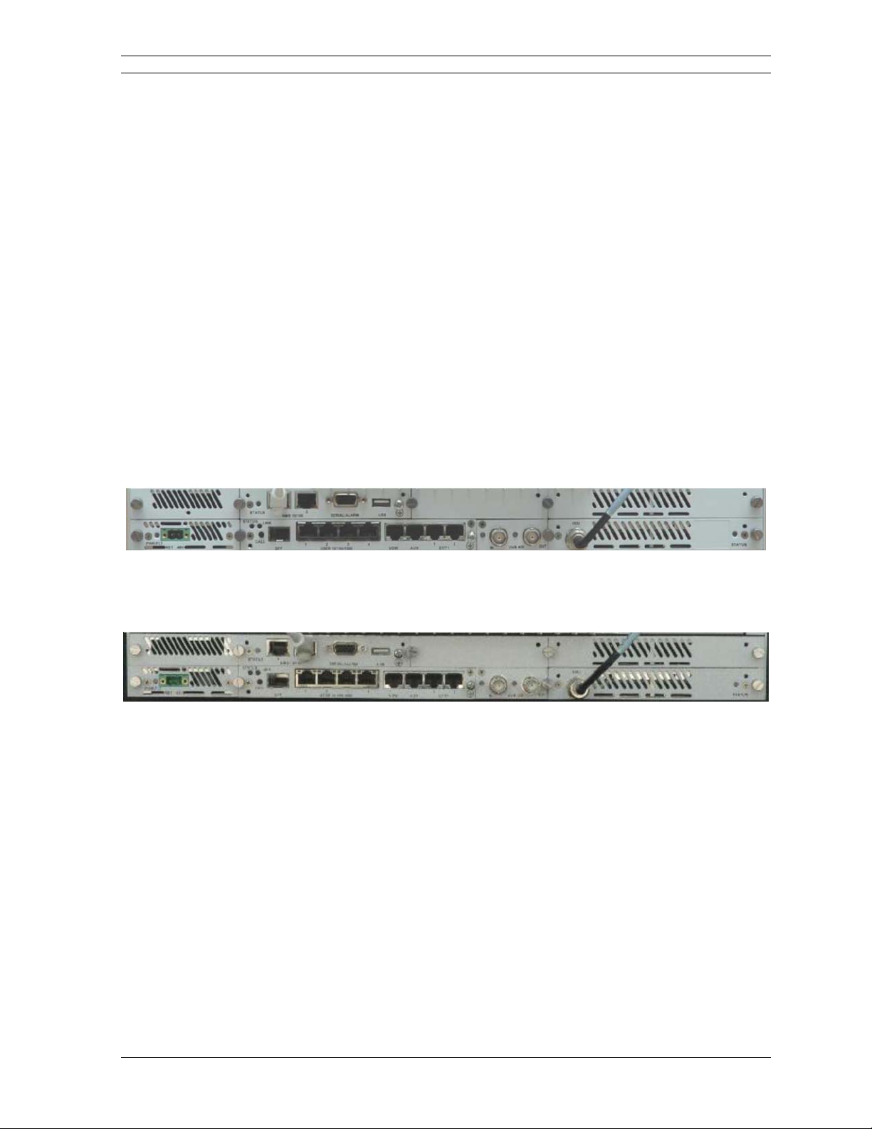
2.3.1 Back Panel
The following illustration shows the general format of a EVENT 5800 back panel.
Figure 2-3. Transceiver Back Panel
This illustration shows the back panel of a transceiver unit that can be configured as a
transmitter or receiver. The following illustration sh ows the back panel of a receiver-only
unit.
Figure 2-4. Receiver-Only Back Panel
Note that the back panel of a EVENT 5800 unit will be slightly different depending on the
number and type of hardware modules installed. Some modules are standard and
included in all units. Optional modules may be ordered and installed to support specific
functional requirements.
2.3.2 Hardware Modules
The lower section of the EVENT 5800 chassis is comprised of hardware modules. The
number and type of modules depends on the type and required functionality. A maximum
of eight of modules can be installed in the chassis. A minimum of five modules are
required in a basic EVENT 5800 configured for 1+0 operation. They are:
Power Supply Module
Controller Module
Modem & I/F Telemetry Module
Master I/O Module
Mini I/O Module
© 2012 Moseley, Inc. All Rights Reserved. 602-16620-01, Rev. A
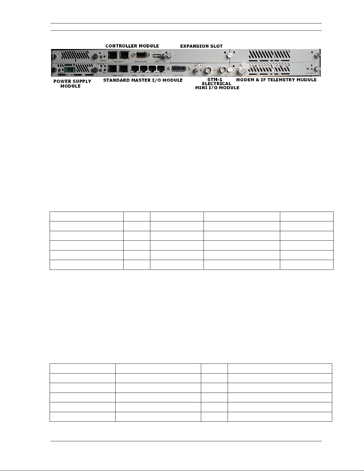
2. System Description 2-5
Figure 2-5. EVENT 5800 Modules
Power Supply Module: A second power supply module can be installed above this
module and is required for 1+1 or 2+0 configurations.
Controller Module: This module is included in all EVENT 5800 units. It supports the
interface to the LCD/keypad and includes connectors for attaching a PC for configuration
and monitoring via the web, CLI, or SNMP interface.
Mini I/O Module: This module can be ASI, an OC3/STM-1 Optical or STM-1 Electrical
Mini I/O Module.
Modem & IF/Telemetry Module: A second Modem & IF Telemetry module can be
installed above this module and is required for 1+1 or 2+0 configurations. E ither module
can be replaced with a Wideband Modem & IF/Telemetry module. The standard Modem
module supports 5-30 MHz channel bandwidths. The Wideband Modem module supports
7-56 MHz channel bandwidths.
Master I/O Module: The Master I/O Module can be one of the following:
Table 2-2. Master I/O Modules
Master I/O Module Payload E1/T1 Ethernet STM-1 Mux/Demux Jumbo Packets
Standard 1-16 10/100 No No
GigE 1-2 10/100/1000 No 4000
Enhanced GigE (Super PDH) 1-2 10/100/1000 No*/Yes* 4000*/9728*
42xE1/T1 1-42 10/100 No No
Enhanced 1-16 10/100 Yes No
*Enhanced GigE Master I/O comes with two options: Support for STM-1 Mux/Demux with
4000 Jumbo Packets or support for 9728 Jumbo Packets.
Expansion Slot: The Expansion Slot can be populated with a 16xE1/T1 Expansion
Module or 21xE1/T1 Expansion Module. The E1/T1 interface cards support up to 63
channels operating simultaneously. Mixing of E1 and T1 channels is n ot support ed. The
E1/T1 interface is in accordance with G.703. One or two E1/T 1 channels can be used as
wayside channels in other operating modes. The Standard Master I/O prov ides up to
16xE1/T1. The Super PDH Master I/O provides up to 42xE1/T1. Additional 16xE1/T1 or
21xE1/T1 are provided by separate Expansion I/O cards. The GigE Master I/O card
provides up to 2xE1/T1. The total possible T1/E1 combinations are provided in the
following table.
Table 2-3. Supported E1/T1 Combinations
Master I/O Expansion I/O E1/T1
Standard None 16xE1/T1 Includes 1-155 Mbps Fast Ethernet
Standard 16xE1 Expansion I/O 32xE1/T1 Includes 1-155 Mbps Fast Ethernet
Standard 21xE1 Expansion I/O 37xE1/T1 Includes 1-155 Mbps Fast Ethernet
42xE1/T1 Master I/O None 42xE1/T1 Includes 1-155 Mbps Fast Ethernet
42xE1/T1 Master I/O 16xE1 Expansion I/O 48xE1/T1 Includes 1-155 Mbps Fast Ethernet
© 2012 Moseley, Inc. All Rights Reserved. 602-16620-01, Rev. A
2. System Description 2-6
Master I/O Expansion I/O E1/T1
42xE1/T1 Master I/O 21xE1 Expansion I/O 63xE1/T1 Includes 1-155 Mbps Fast Ethernet
GigE Master I/O None 2xE1/T1 Includes 1-300 Mbps Gigabit Ethernet
GigE Master I/O 16xE1 Expansion I/O 18xE1/T1 Includes 1-300 Mbps Gigabit Ethernet
GigE Master I/O 21xE1 Expansion I/O 23xE1/T1 Includes 1-300 Mbps Gigabit Ethernet
All modules are inserted from the back panel of the chassis. All modules are hot
swappable. The modularity allows for future upgrades via new hardware modules
without a full replacement of a complete chassis. In addition, repair and maintenance
costs are minimized since individual modules can be repaired or replaced.
2.3.3 Back Panel Connectors
The following illustration shows EVENT 5800 back panel connector locations in a typical,
basic unit.
2.3.3.1 Power Supply Module Connector
-48V Power Input: -48V (Non-isolated Input); 2-pin captive power connector. EVENT
5800 requires an input of -48 Volts DC ±10% at the back panel DC Input connector. The
total required power depends on the option cards and protection configuration (1+0,
1+1). Back panel power connector pins are numbered 1-2, from left to right, when facing
the unit back panel. Pin 1 is the power supply return and is connected to chassis ground
internally. Pin 2 should be supplied with a nominal -48V DC, with respect to the unit
chassis (ground). A ground-isolated supply may be used, provided it will tolerate
grounding of its most positive output.
The recommended power input is -44 to -52V DC at 2 Amps minimum. Any power supply
used must be able to supply a minimum of 125 W to the EVENT 5800.
A mating power cable connector is supplied with EVENT 5800. It is a 2-pin plug, 5 mm
pitch, manufactured by Phoenix Contact, P/N 17 86 83 1 (connector type MSTB 2, 5/2STF). This connector has screw clamp terminals that accommodate 24 AWG to 12 AWG
wire. The power cable wire should be selected to provide the appropriate current with
minimal voltage drop, based on the power supply voltage and length of cable required.
The recommended wire size for power cables under 10 feet in length supplying -48V DC
is 18 AWG, minimum.
EVENT 5800 unit does not have a power on/off switch. When DC power is connected to
the unit, the digital radio powers up and is operational. There can be up to 5 W of RF
power present at the antenna port. The antenna should be directed safely when power is
applied. The EVENT 5800 is normally supplied with an external power sup ply that has an
on/off switch.
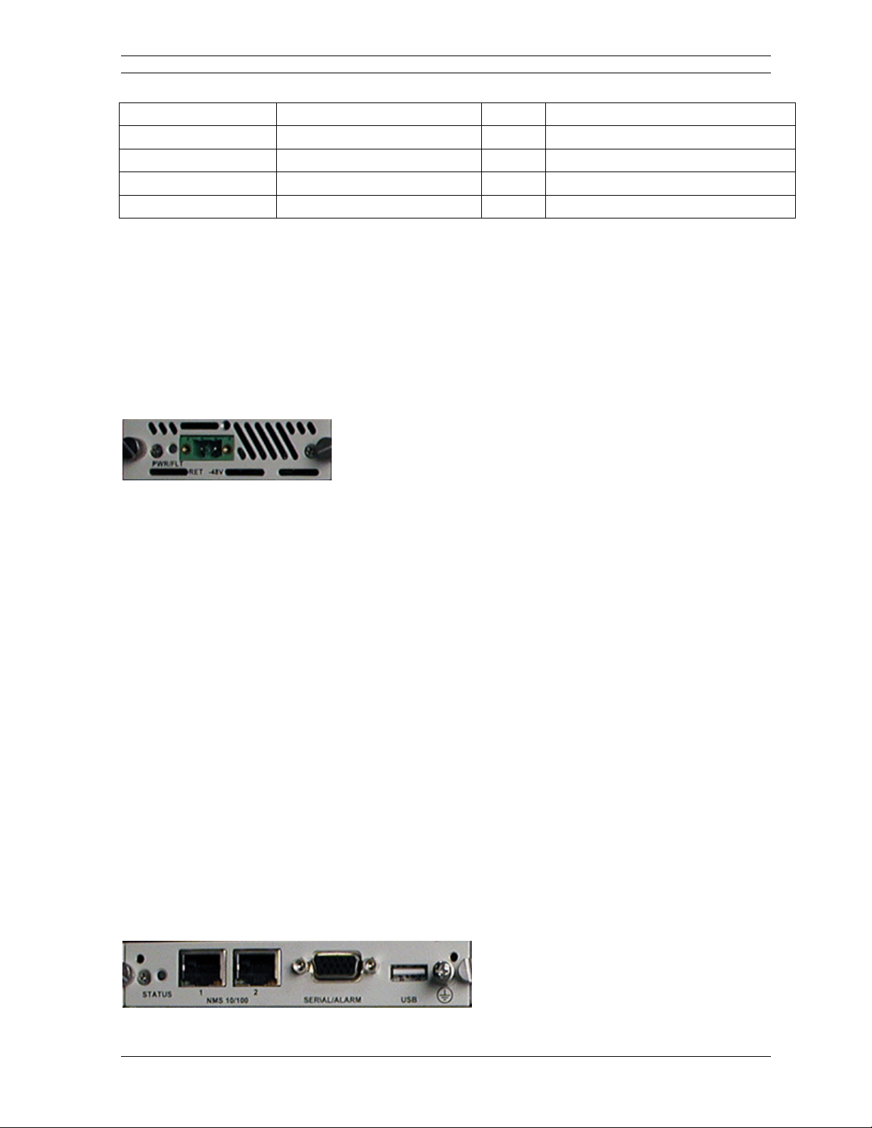
2.3.3.2 Controller Module Connectors
The following illustration shows the connectors on the Controller Module:
© 2012 Moseley, Inc. All Rights Reserved. 602-16620-01, Rev. A
2. System Description 2-7
Serial/Alarm Interface: DB-15HD female connector for two Form-C relay alarm
outputs (rated load: 1A @ 24V DC), two TTL alarm outputs, four TTL alarm inputs, and
Serial Console. The two Form-C relay alarm outputs can be configured to emulate TTL
alarm outputs by installing shorting jumpers JP6 and JP8 for relay alarm 1 and shorting
jumper JP7 and JP9 for relay alarm 2. When configured as TTL, the 2 outputs can
source/sink up to 10 mA at 5 VDC. When an alarm is present, Common is connected to
Normally Closed. Otherwise it is connected to Normally Open .
USB Interface: USB connector, reserved.
NMS 10/100 1: 10/100Base-TX RJ-45 modular local port connector for access to the
Network Management System (SNMP) and Web Interface.
NMS 10/100 2: 10/100BaseTX RJ-45 modular remote port connector for access to the
Network Management System (SNMP). This port to be used for consecutive point
networks.
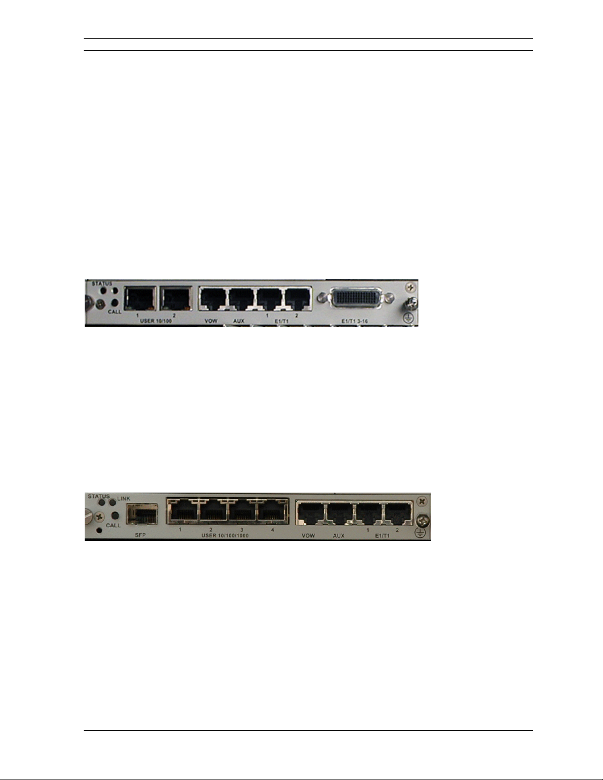
2.3.3.3 Standard Master I/O Module Connectors
The following illustration shows the connectors on the Standard Master I/O Module:
USER 10/100 1: 100Base-TX RJ-45 modular port connector for the local Fast Ethernet
interface.
USER 10/100 2: 100Base-TX RJ-45 modular port connector. This port to be used for
consecutive point networks.
AUX: Data Orderwire Connector: RJ-45 modular port connector for RS422/RS-232 data
at 64 kbps.
E1/T1 1-2: Two E1/T1 (RJ-48C) interface connections.
E1/T1 3-16: Single Molex 60-pin connector containing 14 E1/T1 connections.
2.3.3.4 GigE Master I/O Module Connectors
The following illustration shows th e connectors on the GigE and Enhanced GigE Master
I/O Modules:
SFP: SFP Module slot for 1000Base-T, 1000Base-SX, or 1000Base-LX modules
USER 10/100/1000 1: 1000Base-T RJ-45 modular port connector
USER 10/100/1000 2: 1000Base-T RJ-45 modular port connector
USER 10/100/1000 3: 1000Base-T RJ-45 modular port connector
USER 10/100/1000 4: 1000Base-T RJ-45 modular port connector
AUX: Data Orderwire Connector: RJ-45 modular port connector for RS422/RS-232 data
at 64 kbps.
E1/T1 1-2: Two E1/T1 (RJ-48C) interface connections.
2.3.3.5 42xE1/T1 Master I/O Module Connectors
The following illustration shows the connectors on the 42xE1/T1 Master I/O Module:
© 2012 Moseley, Inc. All Rights Reserved. 602-16620-01, Rev. A
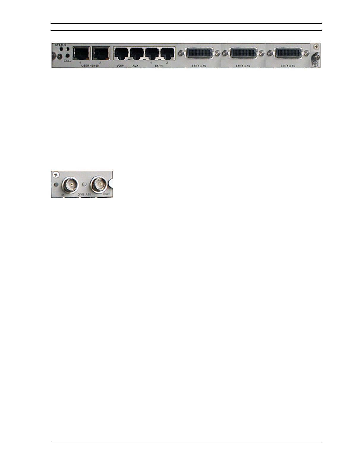
2. System Description 2-8
USER 10/100 1: 100Base-TX RJ-45 modular port connector for the local Fast Ethernet
interface.
USER 10/100 2: 100Base-TX RJ-45 modular port connector. This port to be used for
consecutive point networks.
AUX: Data Orderwire Connector: RJ-45 modular port connector for RS422/RS-232 data
at 64 kbps.
E1/T1 1-2: Two E1/T1 (RJ-48C) interface connections.
E1/T1 3-16: Three Molex 60-pin connectors containing 14 E1/T1 connections each.
2.3.3.6 ASI Mini I/O Module Connectors
The following illustration shows the connectors on the ASI Mini I/O Module:
DVB/ASI Out: BNC connector for the DVB/ASI digital video and DS-3, E-3, and STS-1
interface.
DVB/ASI In: BNC connector for the DVB/ASI digital video and DS-3, E-3, and STS-1
interface.
2.3.3.7 Optional OC-3 Mini I/O Module Connectors
The following connectors are available on an optional OC-3 Mini I/O Module:
OC-3 Out: OC-3 type SC connectors for the OC-3 interface.
OC-3 In: OC-3 type SC connectors for the OC-3 interface.
2.3.3.8 Optional STM-1 Mini I/O Module Connectors
The following connectors are available on an optional STM-1 Mini I/O Module:
STM-1 Out: BNC connector for the STM-1 interface.
STM-1 In: BNC connector for the STM-1 interface.
2.3.4 LEDs
The following paragraphs describe the LEDs on the back panel, and optional
configurations.
2.3.4.1 Back Panel LEDs
All models of the EVENT 5800 support a variety of back panel configurations that depend
on the network interface and capacity configurations. The following illustration shows the
location of LEDs on the back panel. A status LED is provided on the controller, standard
I/O, and each modem card.
Figure 2-7. Back Panel LEDs
These LEDs are described in the following tables and paragraphs.
© 2012 Moseley, Inc. All Rights Reserved. 602-16620-01, Rev. A

2. System Description 2-9
Table 2-5. Modem Status LED
LED STATUS
GREEN Active Locked Link
ORANGE Standby Locked Link (1+1 Non-Diversity Only)
Flashing GREEN Low SNR
Flashing ORANGE Unlocked
Table 2-6. DVB-ASI In Status LED
LED STATUS
GREEN Good ASI input
RED No ASI input
Alternating YELLOW/GRN ASI exceeds radio bit rate (FIFO overflow)
Flashing RED Loss-of-Frame
Flashing GRN No ASI data
Table 2-7. DVB-ASI Out Status LED
LED STATUS
GREEN Active Locked ASI Link
Alternating RED/GREEN No ASI, loss-of-frame
GREEN, occasionally flashing YELLOW Locked ASI link with errors (yellow flashes)
Controller Status LED: This LED is the primary back panel indicator of alarms. An
alarm is generated when a specific condition is identified and is cleared when the
specified condition is no longer detected. When an alarm is posted,
1) The controller status LED turns orange for 5 seconds
2) The controller status LED turns off for 5 seconds
3) The controller status LED flashes orange the number of times specified by the first
digit of the alarm code
4) The controller status LED turns off for 3 seconds
5) The controller status LED flashes orange the number of times specified by the second
digit of the alarm code
Steps 2-5 are repeated for each alarm posted. The entire process is repeated as long as
the alarms are still posted.
For all modules, a green LED indicates normal operation and a red LED indicates mdule
fault. Alarms are also shown in the Web Interface, Command Line Interface (CLI), and .
See the EVENT 5800 User Interface Guide (Moseley Document #602-15173-01).
© 2012 Moseley, Inc. All Rights Reserved. 602-16620-01, Rev. A
2. System Description 2-10
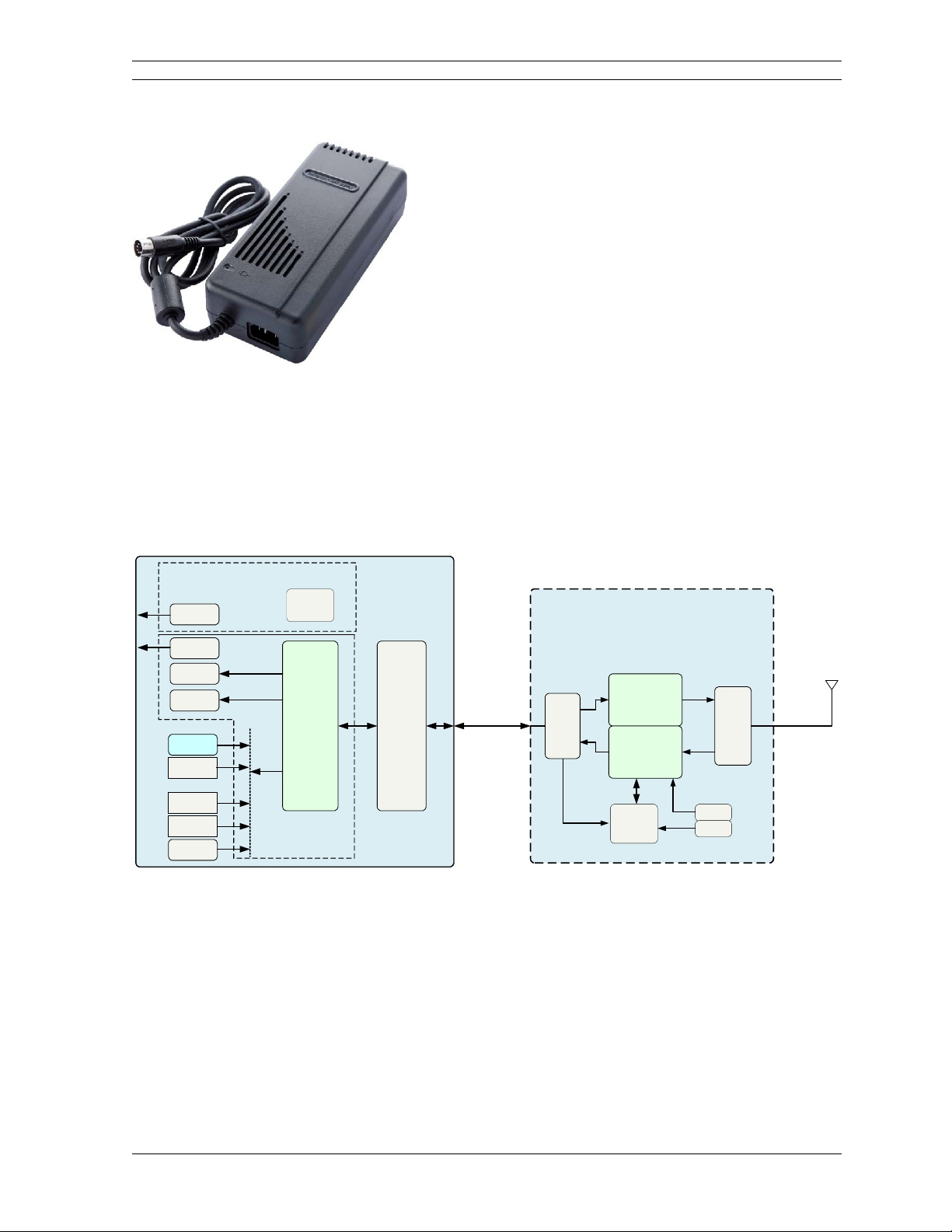
2.3.5 External AC to DC Converter
The DTV LINK TX and RX both are supplied with a high reliability, un iversal input
switching power supply capable of operating within an input range of 90 - 264 VAC; 47 63 Hz. The input is a standard IEC-320-C14 connector. The output voltage is -48V and
is supplied with the 2-pin, 5mm plug.
2.4 Block Diagram & Functional Components
Figure 2-9 shows the EVENT 5800 digital radio and interfaces from a functional point of
view.
Indoor Unit
IDU
CONTROLLER
SNMP 2x
100Base-Tx
User 2x
100Base-Tx
16 T1/E1
64 kbps
Voice
Standard I/O Cards
Optional I/O Cards
(Small Slot)
DVB-ASI
DS-3/ES/
STS-1
Optional I/O Cards
(Large Slot)
2xSTM-1/
OC3
4xDS3/ES/
STS1
STM-1/OC3
Card
uProcessor
FRAMER
Interface
Card
IF MODEM
and
Quadplexer
Card
Multiplexed
IF shielded coax
(TNC)
140 MHz,
350 MHz,
10 MHz,
5.5 MHz,
-48V
Figure 2-9. EVENT 5800 Block Diagram
The functional partitions for the I/O, Modem/IF, power supply modules, up/down
converters, and internal RF duplexing partition are shown. EVENT 5800 comes with the
standard I/O capability which can be upgraded. The Modem/IF function is modular
allowing the addition of a second Modem to support protection or ring architectures. The
power supply is similarly modular. In addition, the radio transceivers are interchangeable
allowing use of a single EVENT 5800 in licensed, unlicensed, and short-haul applications
by swapping the RF component.
The Radio Transceiver RF Up/Down Converter provides the interface to the antenna. The
transmit section up converts and amplifies the modulated Int ermediate Frequency (IF) of
350 MHz from the IF Processor and provides additional filtering. The receive section down
Outdoor Unit
ODU RF
Converter
350
MHz
Transmitter
Up-Converter
5/10
MHz
140
MHz
& Power Amp
Receiver
LNA & Down-
Converter
Commlink
& Processor
Quad
Mux
Tx Out
Rx In
Ref Clk
16 MHz
Div-by-4
Duplexer
Ext
Antenna
N-Type
© 2012 Moseley, Inc. All Rights Reserved. 602-16620-01, Rev. A

2. System Description 2-11
converts the received signal, provides additional filtering, and outputs an IF of 140 MHz
to the IF Processor.
The EVENT 5800 digital radio modem performs QPSK, 16-QAM, 32-QAM, 64-QAM, 128QAM and 256-QAM modulation and demodulation of the payload and forward error
correction using advanced modulation and coding techniques. Using all-digital processing,
the IF Modem uses robust modulation and forward error correction coding to minimize
the number of bit errors and optimize the radio and network performance. The IF Modem
also scrambles, descrambles and interleaves/deinterleaves the data stream in accordance
with Intelsat standards to ensure modulation efficiency and resilience to sustained burst
errors. The modulation will vary by application, data rate, and frequency spectrum. The
highest order modulation mode supported is 256 Quadrature Amplitude Modulation
(QAM). Table 2-5 summarizes the TCM/convolutional code rates for each modulation type
supported by EVENT 5800.
Table 2-8. TCM/Convolutional Code Rates
Modulation Type
Available Code Rates
QPSK 1/2, 3/4, 7/8
16-QAM 3/4, 7/8
32-QAM 4/5, 9/10
64-QAM 5/6, 11/12
128-QAM 6/7, 13/14
256-QAM 7/8, 15/16
The major functions of the EVENT 5800 include:
I/O Processing – EVENT 5800 comes with a standard I/O capability that includes
support for up to 16xT1/E1 and 2x100Base-TX user payloads, 2x100Base-TX for
SNMP. In addition, option cards for DVB-ASI, DS-3/E3/STS-1, 1-2 x STM-1/OC-3, and
4xDS-3/E3/STS-1 may be added. The EVENT 5800 architecture is flexible and allows
for the addition of other I/O types in the future.
Switch/Framing – EVENT 5800 includes an Ethernet Switch and a proprietary
Framer that are designed to support 1+1 protection switching, ring architecture
routing, and overall network control functions.
Network Processor – EVENT 5800 includes a Network Processor which performs
SNMP and Network Management functions.
Modem/IF – The EVENT 5800 modem performs forward-error-correction (FEC)
encoding, PSK/QAM modulation and demodulation, equalization, and FEC decoding
functions. The IF chain provides a 350 MHz carrier and receives a 140 MHz carrier.
Two modems can be used for 1+1 protection or ring architectures.
Power Supply – The EVENT 5800 power supply accepts 48V DC and supplies the
EVENT 5800 and radio transceiver with power. A second redundant power supply may
be added as an optional module.
For the OC-3 configuration, a user rate clock is recovered from clock recovery NCO and
provided to the OC-3/STM-1 I/O card. The Modem Processor and its associated RAM,
ROM, and peripherals control Modem/IF operation. It also provides configuration and
control for both the IF and I/O cards. EVENT 5800 interfaces with the internal Radio
Transceiver to receive and provide modulated transmit and receive waveforms.
The 256-QAM Modem performs the modulation and demodulation of the
payload/wayside/SNMP data and forward error correction using advanced modulation and
© 2012 Moseley, Inc. All Rights Reserved. 602-16620-01, Rev. A

2. System Description 2-12
coding techniques. Using all-digital processing, the 256-QAM Modem uses robust
modulation and forward error correction coding to minimize the number of bit errors and
optimize the radio and network performances. The 256-QAM Modem also scrambles,
descrambles and interleaves/deinterleaves the data stream in accordance with Intelsat
standards to ensure modulation efficiency and resilience to sustained burst errors. The
modulation will vary by application, data rate, and frequency spectrum. The highest
order modulation mode supported is 256 Quadrature Amplitude Modulation (QAM).
The EVENT 5800 digital radio also provides the physical interface for the user payload
and network management. In transmit mode, the Framer merges user payload (ASI, OC3 or Fast Ethernet) with radio overhead-encapsulated network management data. This
combined data stream is transmitted without any loss of user bandwidth. In the receive
mode, the Framer separates the combined data stream received from the 256-QAM
Modem. The EVENT 5800 supports Scalable Ethernet data rates, such as 25 or 50 Mbps
via the 100BaseT data interface port. EVENT 5800 provides network management data
on 10 Mbps ports accessible via the 10/100BaseTX port. The Central Processor Unit
(CPU) provides the embedded control and network element functionality of the OAM&P.
The CPU also communicates with other functions within EVENT 5800 for configuration,
control, and status monitoring.
The power supply converts -48V DC to the DC voltage levels required by each component
in the system.
2.5 Consecutive Point Architecture
The consecutive point network architect ure is based on the proven SONET/SDH ring.
Telecommunications service providers traditionally use the SONET/SDH ring architecture
to implement their access networks. A typical SONET/SDH network consists of the
service provider’s Point of Presence (POP) site and several customer sites with fiber optic
cables connecting these sites in a ring configuration. This architecture lets prov iders
deliver high bandwidth with high availability to their customers.
© 2012 Moseley, Inc. All Rights Reserved. 602-16620-01, Rev. A