

Mosebach X100L Operation And Service Manual

X100L
Load Bank

X100L Load Bank
Read all instructions before using the load bank
Contents
1. Components .............................................................................................................................. 3
Total Assembly ................................................................................................................................. 3
2) Specifications ............................................................................................................................... 4
a) X100L Load Bank ............................................................................................................ 4
3) Receiving ...................................................................................................................................... 5
4) Safety ........................................................................................................................................... 5
a) Grounding ............................................................................................................................. 6
b) Power connections ............................................................................................................... 7
d) Air intakes and exhaust ports ............................................................................................... 7
e) Exhaust temperature ............................................................................................................ 7
f) Connecting and disconnecting ............................................................................................. 8
5) Operation ................................................................................................................................... 8
a) Pre-startup ............................................................................................................................ 8
b) Startup .................................................................................................................................. 9
c) Testing .................................................................................................................................. 9
d) Acuvim II Power Meter.......................................................................................................... 9
e) Shutdown ............................................................................................................................ 10
6) USB Communication Port ....................................................................................................... 10
7) Troubleshooting ....................................................................................................................... 11
8) Replacing Fuses ...................................................................................................................... 12
9) Replacing Resistors ................................................................................................................ 13
10) Preventative Maintenance of the Load Bank ...................................................................... 15
11) Service Parts ...................................................................................................................... 16
Figure list:
1) Total Assembly of X100L Load Bank
2) Grounding Cam
3) Switch Panel
4) Acuvim II Power Meter
5) Typical USB A to USB B male
6) Blower/Control/Main Fuses
7) Thermal Switch
8) Replacing Fuses
9) Switch Panel Support Bolts
10) Replacing Resistors
11) Resistor/Contactor Connections
2
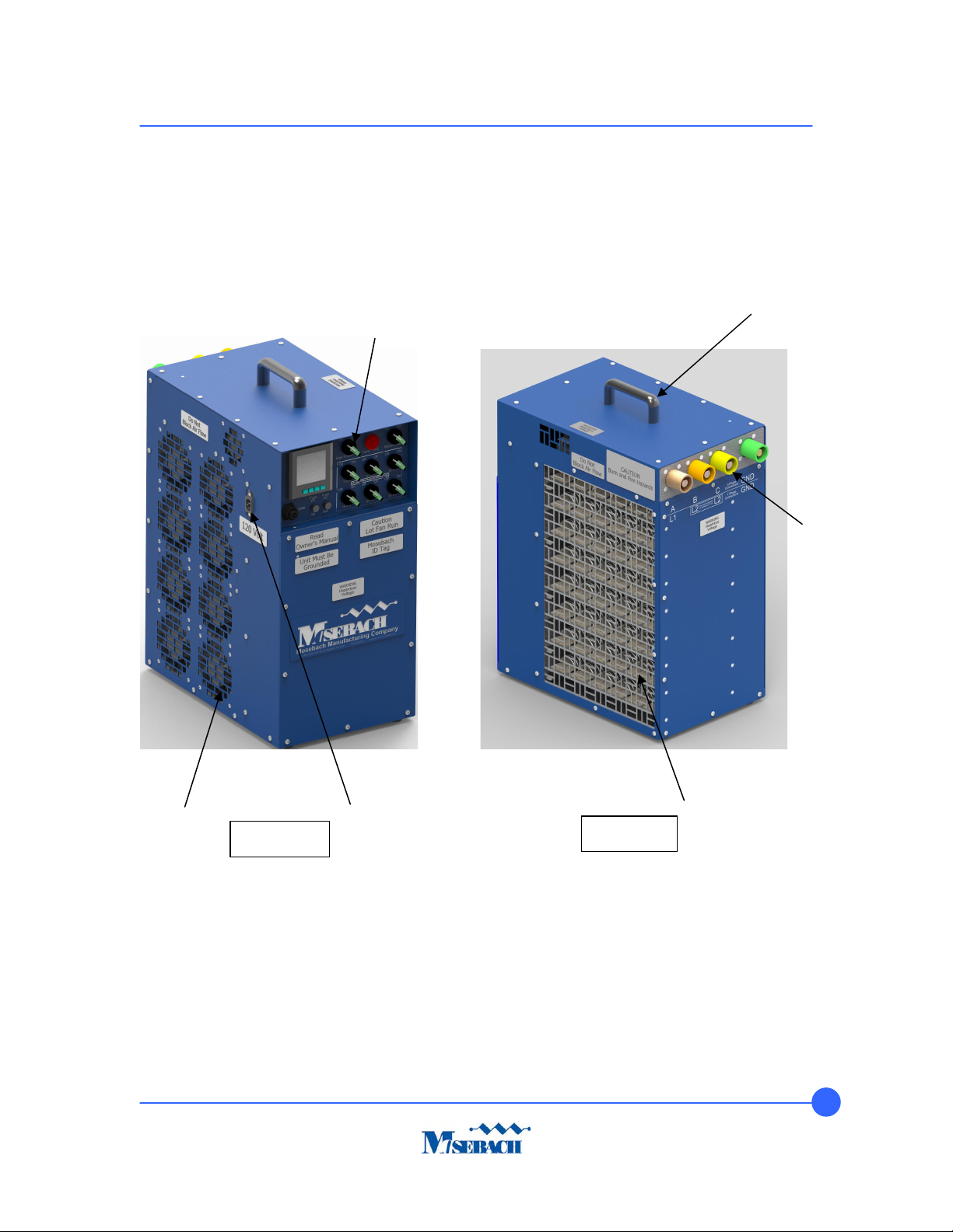
Handle
Customer
Switch Panel
120V Control
1. Components
X100L Load Bank
IMPORTANT INSTRUCTIONS
Lifting
Connections
Fan Panel
Figure 1a
Connection
Exhaust Panel
Figure 1b
Total Assembly
X100L
3
X100L Load Bank
E
lectro
-
statically
powder coat, Blue: PPG PC
TZ50108
2) Specifications
Blower 120VAC, single phase, 60Hz powered from control
Control power 120VAC, single phase, 60 Hz
Rating Continuous duty
Power factor 1.0
Load elements
Enclosure
Environmental 8 x 240V, 420CFM fans to bring outside air into the load bank.
a) X100L Load Bank
Each circuit is connected in delta.
The kW at each step is subject to a manufacturing tolerance of ±5%.
Touch up paint is Pantone 280-c color. Plastikote custom color universal blend.
Air inlet and outlet are covered by metal screens.
Heat is discharged horizontally.
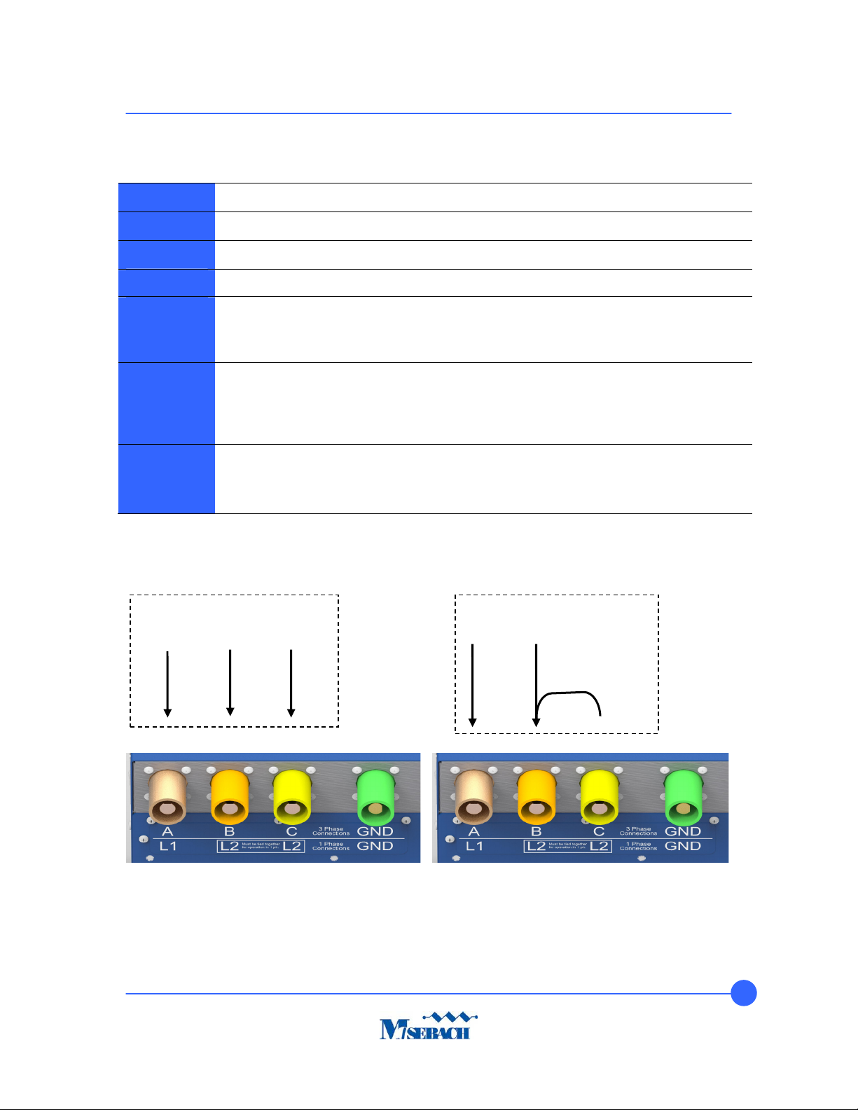
3Ø
Customer Input
1Ø
Customer Input
Jumper
By Customer
4

X100L Load Bank
Input Voltage
Volt.
Mode
kW
Steps
kW
Steps
kW
Steps
kW
Steps
kW
Steps
kW
Steps
Total
Power
Amps
480vAC, 3Ø
Resistive
240vAC, 3Ø
Resistive
208vAC, 3Ø
Resistive
240vAC, 1Ø
Resistive
120vAC, 1Ø
Resistive
480 5 10 10 15 30 30 100 120.3
240 5 10 10 15 30 30 100 240.6
208 3.76 7.51 7.51 11.27 22.53 22.53 75.11 208.5
240 3.33 6.67 6.67 10.00 20.00 20.00 66.67 277.8
120 0.83 1.67 1.67 2.50 5.00 5.00 16.67 138.9
3) Receiving
WARNING! ELECTRIC SHOCK HAZARD. Electric shock can lead to severe injury or death.
If the load bank has been damaged in transit, do not operate until a competent
technician inspects the unit and determines that it can be operated safely.
1. Check the equipment for obvious damage.
2. Document and report any exterior damage to the carrier immediately.
4) Safety
This Load Bank is designed for a variety of loads. Because of this, it is possible that voltages
higher that those applied can be present inside the load bank and at external connections of the
load bank. Work on load bank internal systems should only be attempted by highly trained
technicians and only when power has been disconnected and cannot be reconnected to the unit.
IMPORTANT INSTRUCTIONS
When using electrical appliances, basic precautions should always be followed to reduce the risk
of fire, electrical shock, and injury to persons, including the following:
1) Read all instructions before using this heater/load bank.
2) This load bank is hot when in use. To avoid burns, do not let bare skin touch hot
surfaces. Use handles when moving this load bank.
5
 Loading...