

Mosebach HX30-B, HX30-G, HX30-W Operation And Service Manual

HX30-B
HX30-G
HX30-W
30kW Heater

HX30 Heater
Read all instructions before using the heater
Contents
1) Components .............................................................................................................................. 3
Total Assembly ................................................................................................................................. 3
2) Specifications ............................................................................................................................... 3
a) HX30 Heater .................................................................................................................... 4
3) Receiving ...................................................................................................................................... 4
4) Safety ........................................................................................................................................... 5
a) Ground Cam ......................................................................................................................... 6
b) Power connections ............................................................................................................... 6
d) Air intakes and exhaust ports ............................................................................................... 6
e) Exhaust temperature ............................................................................................................ 7
f) Connecting and disconnecting ............................................................................................. 7
5) Operation ................................................................................................................................... 7
a) Pre-startup ............................................................................................................................ 7
b) Startup and Operation .......................................................................................................... 8
c) Shutdown ............................................................................................................................ 10
6) Troubleshooting ....................................................................................................................... 10
7) Replacing Fuses ...................................................................................................................... 12
8) Replacing Resistors ................................................................................................................ 16
9) Preventative Maintenance of the Heater ................................................................................. 17
10) Service Parts ...................................................................................................................... 18
2
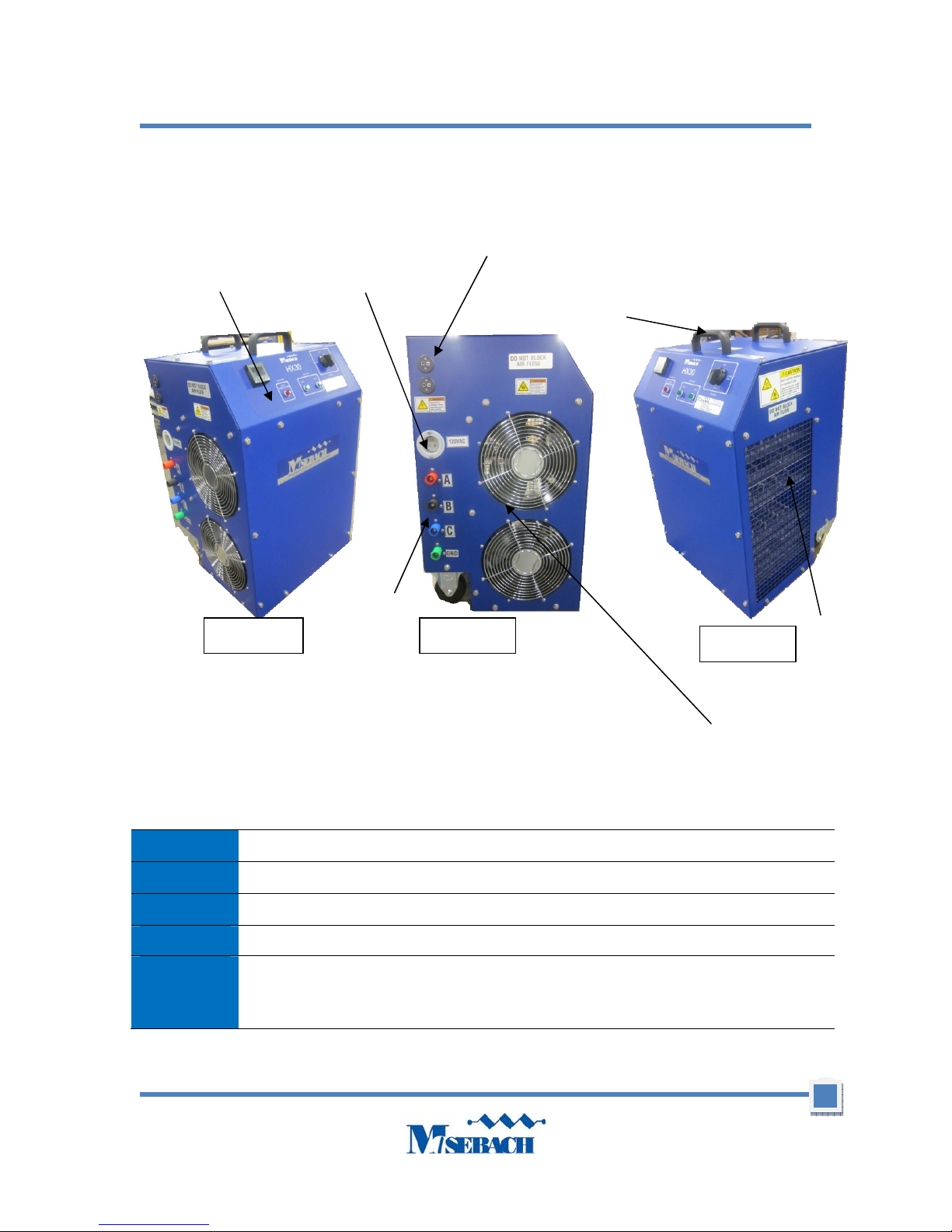
Switch Panel
Pull Handle
Thermocouple
Customer
Power
1
20VAC
1. Components
HX30 Heater
IMPORTANT INSTRUCTIONS
Connections
Receptacle
Connections
Exhaust Panel
Figure 1b Figure 1a
Figure 1c
Total Assembly
HX30
Fan Panel
2) Specifications
Blower 120VAC, single phase, 60Hz powered from control
Control power 120VAC, single phase, 60 Hz
Rating Continuous duty
Power factor 1.0
Load elements
Each circuit is connected in delta.
The kW at each step is subject to a manufacturing tolerance of ±5%.
3
HX30 Heater
Electro
-
statically powder coat, Blue: PPG PCTZ50108
Ground
Ground
Enclosure
Environmental Quantity two 120V, 850CFM fans to bring outside air into the heater.
Unit Weight 105 lbs.
Dimensions 18.2”x16.2”x27”
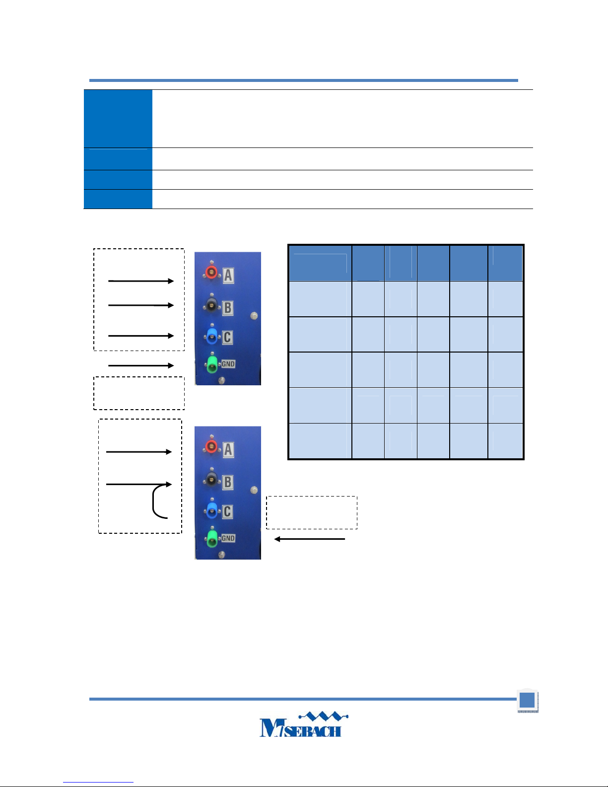
a) HX30 Heater
Customer Input
Touch up paint is Pantone 280-c color. Plastikote custom color universal blend.
Air inlet and outlet are covered by metal screens.
Heat is discharged horizontally.
3Ø
Input Voltage
480vAC, 3Ø
Resistive
Volt.
Mode
480 15 15 30 36.1
kW
Steps
240vAC, 3Ø
Resistive
240 15 15 30 72.25
Customer
1Ø
Customer Input
208vAC, 3Ø
Resistive
240vAC, 1Ø
Resistive
120vAC, 1Ø
Resistive
240 11.25 11.25 22.5 62.5
240 10 10 20 83.3
240 2.5 2.5 5 41.7
kW
Steps
Total
Power
Amps
Jumper
By
Customer
Customer
3) Receiving
WARNING! ELECTRIC SHOCK HAZARD. Electric shock can lead to severe injury or death.
If the heater has been damaged in transit, do not operate until a competent
technician inspects the unit and determines that it can be operated safely.
1) Check the equipment for obvious damage.
2) Document and report any exterior damage to the carrier immediately.
4

HX30 Heater
4) Safety
This heater is designed for a variety of loads. Because of this, it is possible that voltages higher
that those applied can be present inside the heater and at external connections of the heater.
Work on heater internal systems should only be attempted by highly trained technicians and only
when power has been disconnected and cannot be reconnected to the unit.
IMPORTANT INSTRUCTIONS
When using electrical appliances, basic precautions should always be followed to reduce the risk
of fire, electrical shock, and injury to persons, including the following:
1) Read all instructions before using this heater.
2) This heater is hot when in use. To avoid burns, do not let bare skin touch hot
surfaces. Use handles when moving this heater. Keep combustible materials, such
as furniture, pillows, bedding, papers, clothes, and curtains at least 8 feet
(1.8 meters) from the exhaust of the heater and keep them away from the sides and
rear.
3) Extreme caution is necessary when any heater is used by or near children or invalids
and whenever the heater is left operating and unattended.
4) Always unplug heater when not in use.
5) Do not operate any heater with a damaged cord or plug or after the heater
malfunctions or has been dropped or damaged in any manner. Discard heater or
return to authorized service facility for examination and/or repair.
6) Do not use outdoors.
7) Do not use in wet or moist locations
8) This heater is not intended for use in wet indoor environments.
9) Do not run cord under carpeting. Do not cover cord with throw rugs, runners, or
similar coverings. Do not route cord under furniture or appliances. Arrange cord away
from traffic areas and where it will not be tripped over.
10) To disconnect heater, turn controls off, then remove plug from outlet.
11) Connect to properly grounded outlets only.
12) Do not insert or allow foreign objects to enter any ventilation or exhaust opening as
this may cause an electric shock or fire, or damage the heater.
13) To prevent a possible fire, do not block air intakes or exhaust in any manner. Do not
use on soft surfaces, like a bed, where openings may become blocked.
14) A heater has hot and arcing or sparking parts inside. Do not use it in areas where
gasoline, paint, or flammable liquids are used or stored.
5
HX30 Heater
Power
15) Use this heater only as described in this manual. Any other use not recommended by
the manufacturer may cause fire, electric shock, or injury to persons.
16) Always plug heaters directly into a wall outlet/receptacle. Never use with a relocatable power tap (outlet/power strip).
17) This heater includes a visual alarm to warn that parts of the heater are getting
excessively hot. If the alarm light goes on, immediately turn the heater off and inspect
for any objects on or adjacent to the heater that may cause high temperatures. DO
NOT OPERATE THE HEATER WITH THE ALARM LIGHT ON.
18) SAVE THESE INSTRUCTIONS
Control Power
a) Ground Cam
WARNING! ELECTRIC SHOCK HAZARD. The ground cam must be connected to earth
ground. Operating without a grounding connection could lead to injury or
death.
When the heater is in operation the ground cam must be firmly and electrically connected to earth
ground. Failure to do so could allow deadly voltage to be present on the surface of the enclosure.
The grounding connection provides a low resistance path to ground.
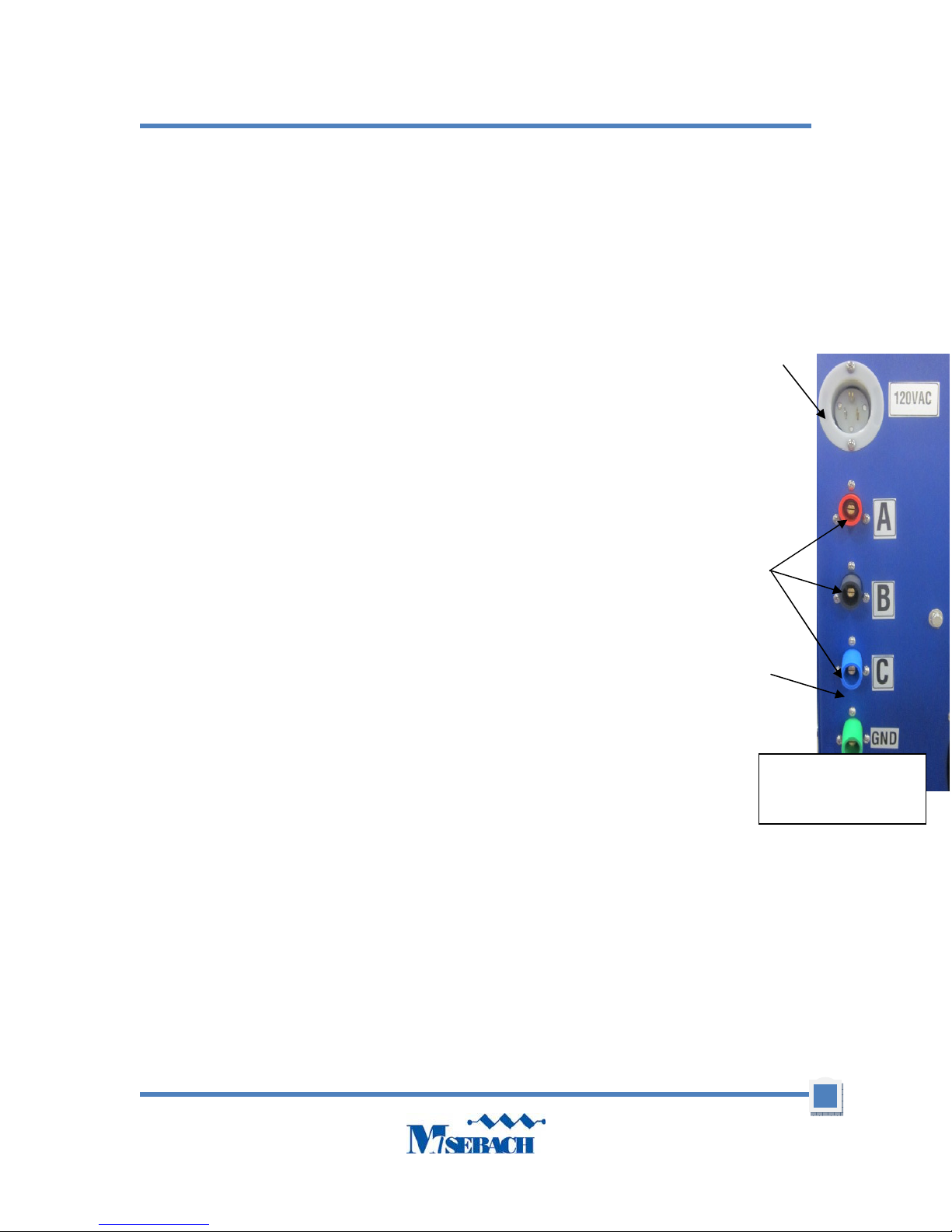
b) Power connections
WARNING! ELECTRIC SHOCK HAZARD. All power connections must be connected or
guarded. Failure to do so will expose operators to possible shock and the
possibility of grounding-out or shorting-out of the test power source,
Power
Ground
c) Control Power
Use 120V type S or type SJ jacketed cord to a wall connection. Cord and service
rated to 10 AMP minimum. (see figure 2.)
d) Air intakes and exhaust ports
Caution! All air intakes and exhaust ports must be clear and fully open. This heater has
one air intake designed for proper air flow. Reducing or blocking air flow will lead to
overheating and heater failure.
High volumes of cooling air are needed to prevent load elements from overheating. By their very
nature, resistors under load convert electrical energy to heat. This heat must be removed from
the unit. The blower, intake, and exhaust ports are sized to provide the proper amount of cooling
air. Preventing or limiting air flow will allow the heater to overheat.
To increase the life of the load elements, allow the fans to run at least three minutes after the load
is removed or until exhaust air is cool.
Figure 2. Ground,
Power and Control
6
 Loading...