

Mosconi GLADEN ONE 7.6 Owner's Manual
MOSCONI si riserva il diritto di apportare modifiche o miglioramenti ai prodotti illustrati senza alcun preavviso. La
disponibilità dei prodotti illustrati può essere sottoposta a variazioni. I prodotti presenti su questo MANUALE D’USO
rappresentano solo una parte dei prodotti MOSCONI. Tutti i marchi eventualmente citati sono stati utilizzati esclusivamente a
scopo descrittivo ed ogni diritto appartiene ai relativi proprietari. La riproduzione totale o parziale di questo MANUALE
D’USO è vietata.
MOSCONI hält sich jeder Art von Änderungen oder Verbesserung ohne Ankündigung vor. Die Verfügbarkeit der gezeigten
Produkte kann variieren. Alle Produkte, die in dieser Anleitung beschieben sind, sind ein Teil von MOSCONI. Alle
Markenrechte gehören dem Eigentümer MOSCONI. Ein total oder auch auszugsweiser Nachdruck ist nicht erlaubt.
MOSCONI reserves the right to modify or improve the products described here without notice. The availability of the
displayed products may vary. Products described in this MANUAL are a portion of all MOSCONI products. All trademarks
mentioned are used for descriptive purposes and all rights are reserved by their respective owners. The total or partial
reproduction of this MANUAL is prohibited.
GARANZIA, GARANTIEKARTE, WARRANTY
CONDIZIONI DI GARANZIA
RESTITUIRE, ASSIEME AL PRODOTTO DA RIPARARE, IL PRESENTE FOGLIO COMPILATO IN
TUTTE LE SUE PARTI CON ALLEGATO IL DOCUMENTO FISCALE D’ACQUISTO.
GARANTIEBEDINGUNGEN
DIE GARANTIEKARTE BITTE VOLLSTÄNDIG AUSGEFÜLLT ZUSAMMEN MIT
EINER FEHLERBESCHREIBUNG UND DER RECHNUNG EINSCHICKEN.
WARRANTY CONDITIONS
COMPLETE ALL SECTIONS AND RETURN THIS DOCUMENT ALONG WITH A) THE PRODUCT TO
REPAIR AND B) THE ORIGINAL DATED PURCHASE RECEIPT
MOS garantisce i prodotti MOSCONI per 24 mesi dalla data di acquisto dichiarata nel presente riquadro e nel documento
fiscale di acquisto (scontrino o fattura da allegare alla presente in caso di restituzione per riparazione al rivenditore).
Il numero di matricola del presente certificato, deve corrispondere a quello stampigliato sull’apparecchio da riparare.
MOS non è responsabile di eventuali danni causati a persone che usano impropriamente i prodotti MOSCONl o a cose a
questi collegate.
MOS gewährt 24 Monate Garantie auf MOSCONI Produkte.
Entscheident ist das Kaufdatum auf der Rechnung des autorisierten MOSCONI Fachhändlers.
Die Seriennummer des Produkts muss mit der Seriennummer der abgestempelten Garantiekarte
übereinstimmen.
MOS übernimmt keinerlei Haftung bei unsachgemäßem Einbau und Gebrauch des Produkts.
MOS extends a warranty to MOSCONI products for 24 months from the date of the original purchase as declared in the
appropriate box and in the original purchase receipt. Enclose the dated purchase receipt when sending the product for
return or repair to the authorized dealer.
The serial number of this certificate must correspond to the one stamped on the returned product.
MOS is not responsible for damages or injury caused by improper installation or operation of the product.
Name
Address
e-mail & Phone
Client Autorized Dealer
Model
Serial Number
Product
Designed and Manufactured in Italy by MOS - - www.mosconi.orgwww.mosconi-system.it
GLADEN ONE 70.6
GLADEN AUDIO EUROPE
ITA, DEUT, ENG
WARNING!
DISCONNECT THE BATTERY LEADS
BEFORE INSTALLATION, MAINTENANCE
OR REMOVAL.
12V
WARNING!
USE ONLY IN VEHICLES WITH A 12 VOLT
NEGATIVE GROUND
AVVERTENZE:
INTERROMPERE IMMEDIATAMENTE L’USO IN CASO DI
PROBLEMI. Diversamente si potrebbero causare danni alla
persona o al prodotto. Per riparazioni, rivolgersi ad un
rivenditore autorizzato MOSCONI.
NON SMONTARE O MODIFICARE. Tale azione potrebbe
causare incidenti, incendi o scosse elettriche. Ogni tipo di
manomissione comporta il decadimento immediato della
garanzia.
I CO LLEGAMENT I E L’IN STALLAZIONE DEVONO
ESSERE EFFETTUATI DA PERSONALE QUALIFICATO. I
collegamenti e l’installazione dell’apparecchio richiedono
conoscenze tecniche ed esperienza particolari. Per ragioni
di sicurezza, contattare sempre un rivenditore autorizzato
per eseguire una corretta installazione del prodotto.
NON INSTALLARE IN LUOGHI ECCESSIVAMENTE UMIDI
O POLVEROSI. Evitare di installare l’apparecchio in luoghi
eccessivamente umidi o polverosi. La presenza di umidità o
polvere all’interno del prodotto potrebbe causare problemi di
funzionamento.
NON INSTALLARE A CONTATTO DI SUPERFICI
SENSIBILI AL CALORE. L’amplificatore può raggiungere
una temperatura superiore agli 80°, il contatto con superfici
e materiali sensibili al calore potrebbe causare incendi o altri
danni
NELL’EFFETTUARE I FORI, NON DANNEGGIARE I TUBI
O I CAVI. Nell’effettuare i fori nel telaio per l’installazione,
fare attenzione a non entrare in contatto, danneggiare o
ostruire i tubi, i condotti della benzina, i serbatoio i cavi
elettrici. La non osservanza di queste precauzioni potrebbe
causare incendi.
NON OSTRUIRE I CANALI DI VENTILAZIONE. Bloccandoli
si p otrebb e causare un surris caldam ento inter no
dell’apparecchio che potrebbe dare luogo a incendi.
UTILIZZARE IL PRODOTTO IN VEICOLI CON BATTERIA
DA 12 V. Un utilizzo diverso da quello indicato potrebbe
causare incendi, scosse elettriche o altri incidenti.
PRIMA DI ESEGUIRE I COLLEGAMENTI, SCOLLEGARE
IL CAVO DEL TERMINALE NEGATIVO DELLA BATTERIA.
Altrimenti potrebbero derivare scosse elettriche o altre
lesioni dovute a cortocircuiti.
ESEGUIRE CORRETTAMENTE I COL LEGAMENTI.
Utilizzare cavi di dimensioni adeguate e rispettare tutte le
polarità, altrimenti potrebbero derivarne incendi o danni al
prodotto.
EVITARE CHE I CAVI SI IMPIGLINO AGLI OGGETTI
CIRCOSTANTI. Effettuare i collegamenti seguendo le
istruzioni in modo che i cavi non interferiscano con la guida. I
cavi o i fili che interferiscono o si impigliano in parti quali lo
sterzo, la leva del cambio, i pedali, ecc. potrebbero essere
pericolosi.
SISTEMARE I CAVI IN MODO CHE NON VENGANO
PIEGATI O COMPRESSI DA PARTI METALLICHE
TAGLIENTI. Per evitare che vengano danneggiati o piegati,
sistemare i cavi e i fili lontano da parti mobili (quali le guide
dei sedili) o da parti taglienti o aguzze. Se i cavi vengono fatti
passare attraverso un foro metallico, utilizzare un anello di
gomma per evitare che l’isolante dei cavi venga tagliato dal
bordo metallico del foro.
PER ESEGUIRE I COLLEGAMENTI DI TERRA, NON
UTILIZZARE BULLONI O DADI DEI SISTEMI DI FRENATA
O DI STERZO. Non utilizzare MAI bulloni o dadi dei sistemi
di frenata e di sterzo (o di qualsiasi altro sistema di
sicurezza), o dei serbatoi per eseguire l’installazione o per i
collegamenti di terra. L’utilizzo di queste parti potrebbe
inibire il controllo del veicolo e causare incendi o altro.
USARE FUSI BILI DI RIC AMBIO DI A DEGUATO
AMPERAGGIO. Altrimenti potrebbero derivarne incendi o
scosse elettriche.
UTILIZZARE LE PARTI ACCESSORIE SPECIFICATE E
INSTALLARLE IN MODO CORRETTO. Assicurarsi di
utilizzare accessori specifici in dotazione.
NON EFFETTUARE ALCUNA OPERAZIONE CHE POSSA
DISTOGLIERE L’ATTENZIONE DALLA GUIDA DEL
VEICOLO. Qualsia si operazione che n ecessita di
attenzione prolungata deve essere effettuata solo dopo il
completo arresto del veicolo. Arrestare sempre il veicolo in
un luogo sicuro prima di effettuare queste operazioni. In
caso contrario si potrebbero causare incidenti.
TENERE IL VOLUME AD UN LIVELLO CHE PERMETTA DI
UDIRE I RUMORI ESTERNI DURANTE LA GUIDA. Livelli
eccessivi di volume, in grado di coprire suoni quali le sirene
dei mezzi di soccorso o segnali stradali di attenzione (ad
esempio, passaggi a livello, ecc.) possono essere pericolosi
e provocare incidenti. Inoltre, l’ascolto di audio ad alto
volume in auto può provocare danni all’udito.
ACHTUNG! WARNHINWEISE:
STELLEN SIE DEN GEBRAUCH IM FALLE EINER
STÖRUNG EIN. Die Nichteinhaltung kann zu einem
Schaden an dem Produkt führen. Für eine Reparatur
wenden Sie sich bitte an einen autorisierten
MOSCONI Fachhändler.
ZERLEGEN ODER MODIFIZIEREN SIE DAS PRODUKT
NICHT: Dies könnte zu Unfällen, Feuer oder elektrischen
Schocks führen. Jeglicher Umbau oder Modifikation des
Produkts hebt sämtliche Garantieansprüche sofort auf.
DER EINBAU SOWIE DIE VERKABELU NG DES
PRODUKTS SOLLTE VON QUALIFIZIERTEM PERSONAL
AUSGEFÜHRT WERDEN . Besonderes techn isches
Wissen und Erfahrung ist für den Einbau und die
Verkabelung dieses Produkts von Nöten. Um die Sicherheit
zu wahren, kontaktieren Sie immer einen autorisierten
Händler, der dieses Produkt fachgerecht einbaut.
NICHT AN FEUCHTEN ODER STAUBIGEN PLÄTZEN
EINBAUEN. Vermeiden Sie den Einbau des Produkts
innerhalb übermäßig feuchten oder staubigen Orten. Das
eindringen von Feuchtigkeit oder Staub kann zu einem
Ausfall führen.
NICHT IN DER NÄHE VON HITZEEMPFINDLICHEN
FLÄCHEN EINBAUEN. Die Endstufe kann Temperaturen
bis zu 80ˆC errei che n und der Konta kt mit
hitzeempfindlichen Bereichen birgt eine Brandgefahr und
kann zu Schäden führen.
KEINE L EITUNGEN UND KABEL WÄHR END DES
BOHRENS VON LÖCHERN BESCHÄDIGEN. Wenn Sie
Löcher bohren, vermeiden Sie Beschädigungen. Besonders
den Kontakt mit: Leitungen, der Kraftstoffleitung, dem Tank
und elektrischen Kabeln . Die U nterlassu ng dieser
Vorsichtsmaßnahmen führt zu einer Feuergefahr.
BLOCKIEREN SIE KEINE ENTLÜFTUNGS ÖFFNUNGEN
ODER HITZESENKENDE ELEMENTE. Das Blockieren von
Öffnungen oder hitzesenkenden Elementen kann die
Temperaturen innerhalb des Verstärkers erhöhen. Dies
kann zu Feuer führen.
BENUTZEN SIE DIESES PRODUKT AUSSCHLIEßLICH IN
FAHRZEUGEN MIT 12V STROMVERSORGUNG. Die
Benutzung des Produkts bei anderer Stromstärke als 12V
kann zu Feuer, elektrischen Schocks oder Unfällen führen.
KLEMMEN SIE DIE NEGATIVE BATTERIELEITUNG VOR
DEM ANSCHLUSS DES GERÄTS AB. Die Nichterfüllung
kann elektrische Schocks oder andere Beschädigungen
aufgrund eines Kurzschlusses hervorrufen.
STELLEN SIE SACHGEMÄßE VERKABELUNG SICHER.
Um Feuer und Schaden am Produkt zu vermeiden,
verwenden Sie passend starke Kabel und achten Sie auf
Polarität der Anschlüsse.
VERMEIDEN SIE EIN DURCHEINANDER VON KABELN
MIT FAHRZEUGTEILE N. Stellen Sie sachg emäße
Verkabelung laut Bedienungsanleitung sicher, so dass die
Kabel den eigentlichen Betrieb eines Fahrzeugs nicht
behindern. Kabel, die sich mit Lenkelementen, dem
Schalthebel, Pedalen etc. verwickeln können gefährlich
sein.
LEGEN SIE DIE KABEL SO AUS, DASS SIE NICHT
GEK RÜ MM T SI N D OD ER VON SCH AR F EN
METALLISCHEN KANTEN EINGEDRÜCKT WERDEN. Um
eine Beschädigung und eine Krümmung der Kabel zu
vermeiden, verlegen Sie die Kabel weit entfernt von
beweglichen Teilen (wie Sitzschienen) und von scharfen und
spitzigen Fahrzeugteilen. Falls die Kabel durch ein Loch des
Metalls gelegt werden, benutzen Sie einen Gummiring, um
zu gewährleisten, dass die Kabelisolation nicht von einer
scharfen Kante aufgeschnitten wird.
FÜR EIN E N MA SS EA N SC HL US S N IE MA LS
SCHRAUBEN VERWENDEN, DIE ZUM LENK- ODER
BREMSSYSTEM GEHÖREN. NIEMALS Schrauben des
Len k - o de r Bre m ss y st e ms (o de r and e re r
Sicherheitssysteme) oder des Tanks verwenden, um einen
Masseanschluss herzustellen. Der Gebrauch einer dieser
Teile kann die Fähigk eit, das Auto zu s teuer n,
beeinträchtigen und Unfälle, Feuer oder anderen Schaden
hervorrufen.
NUTZEN SIE GERÄTE SCHUTZSICHERUNGEN MIT
HINR EI CHE ND ER AMP ER E BEL AST BA RKE IT.
Andererseits können Feuer und elektrische Schocks
auftreten.
BENUTZEN SIE EINWANDFREIE ZUBEHÖRTEILE UND
BEFOLGEN SIE DIE INSTALLATIONSANLE ITUNG.
Benut zen Sie aus sch lie ßli ch vor sch rif tsmä ßig e
Zubehörteile. Der Gebrauch anderer Komponenten kann
das Produkt beschädigen oder zu einem unsachgemäßen
Einbau führen. Komponenten könnten nicht sicher verkabelt
sein und eine Fehlfunktion oder Gefahr darstellen.
GEBRAUCHEN SIE DAS PRODUKT NICHT SO, DASS
IHRE AUFMERKSAMKEIT VOM FAHREN ABGELENKT
IST. Jede Handlung, die kontinuierliche Aufmerksamkeit
verlangt, muss im stehenden Zustand des Fahrzeugs
vollzogen werden. Beim Ausführen solcher Handlungen
stoppen sie das Fahrzeug immer in einer sicheren Zone.
Nichteinhaltung kann Unfälle verursachen.
HALTEN SIE DIE LAUTSTÄRKE AUF EINEM SOLCHEN
LEVEL, DER IHNEN ERLAUBT, EXTERNE GERÄUSCHE
WÄHREND DES FAHRENS ZU HÖREN. Überhöhte
Lautstärkepegel, welche die Sirene von Notfallfahrzeugen,
das Geräusch von Eisenbahnen etc. übertönen, können
gefährlich sein und Unfälle verursachen. Außerdem kann
das sehr laute Musikhören innerhalb eines Fahrzeugs das
Gehör schädigen.
WARNING! CAUTION:
IN CASE OF TROUBLE IMMEDIATELY DISCONTINUE
USE. Failure to comply may cause injury or damage the
product. For repair please contact an authorized MOSCONI
dealer.
DO NOT DISASSEMBLE OR MODIFY THE PRODUCT:
This action may result in accidents, fire or electric shock. Any
alteration or modification to the product immediately voids
any expressed or implied warranty.
THE IN STALLATION AND CON NECTION OF THE
PRODUCT SHOULD BE PERFORMED BY QUALIFIED
PERSONNEL. The installation and connection of the
product require specific technic al background and
experience. . For safety reasons, always contact an
authorized dealer to install the product in a correct way.
DO NOT INSTALL IN AREAS PARTICULARY HUMID OR
DUSTY. Avoid installing the product in areas excessively
humid or dusty. Presence of humidity or dust inside the
product can cause malfunction.
DO NOT INSTALL NEXT TO HEAT SENSI TIVE
SURFACES. The amplifier may reach temperatures in
excess of 80°C (176°F) and contact with heat sensitive
surfaces may cause a fire hazard and damage to the
surface.
WHILE DRILLING HOLES, DO NOT DAMAGE TUBING
AND CABLES. While drilling holes in your vehicle during
installation, pay close attention to avoid damaging, blocking
or contact with: tubing, the fuel lines, the fuel tank and
electrical cables. Failure to follow these precautions will
pose a fire hazard and damages.
DO NOT OBSTRUCT VENTS OR HEAT SINKING PANELS.
Blocking vents or heat sinking panels may cause increased
temperatures inside the amplifier. This may cause a fire
hazard.
USE THIS PRODUCT EXCLUSIVELY IN VEHICLES WITH
12V POWER. Using the product with electrical power other
than 12V may cause fires, electric shock or other accidents.
DISCONNECT THE NEGATIVE (GROUND) BATTERY
LEAD BEFORE CONNECTING THE PRODUCT. Failure to
do so may cause electric shock or other damage and injury
due to short circuit.
ENSURE PROPER CONNECTIONS. To avoid fire hazard
and damage to the product, use cables of proper gauge and
pay close attention to the polarity of the connections.
AVOID TANGLING THE CABLES TO VEHICLE PARTS.
Make proper connections by following the instructions so
that the cables do not interfere with proper vehicle operation.
Cables that tangle with steering components, gear lever,
brake pedals, etc may be dangerous.
LAY OUT THE CABLES TO ENSURE THAT THEY ARE
NOT BENT OR COMPRESSED BY SHARP METAL
EDGES. To avoid damaging or bending the cables, lay out
the cables far from moving parts (such as the seat rails) and
from sharp or pointy vehicle parts. If the cables are to pass
through a hole in a metal sheet, use a rubber ring to ensure
that the cable insulation won't be cut by any sharp edge.
TO ESTABLISH A GROUND CONNECTION DO NOT USE
BOLTS THAT BELONG TO THE STEERING OR BRAKING
SYSTEM. NEVER use bolts from the steering or braking
system (or any other safety system) or the fuel tank to
establish a ground connection. Using any of these parts
may impair your ability to control the vehicle and cause
accidents, fire or other damage.
USE FUSES WITH ADEQUATE AMP RATING. Otherwise
there may be fires or electric shock.
USE THE CORRECT ACCESSORY PARTS AND FOLLOW
THE INSTALLATION INSTRUCTIONS. Be sure to use only
specified accessory parts. Using other components may
damage the product or result in improper installation.
Components may not be connected securely and cause
malfunction or danger.
DO NOT OPERATE THE PRODUCT IN WAYS THAT MAY
DISTRACT YOUR ATTENTION FROM DRIVING. Any
operation that requires continued attention must be done
when the vehicle is at full stop. Always stop the vehicle in a
safe area when performing such operations. Failure to do so
may cause accidents.
MAINTAIN THE VOLUME AT LEVELS THAT ALLOW
EXTERNAL NOISES TO BE AUDIBLE WHILE DRIVING.
Excessive volume levels, capable of blocking the sound of
emergency vehicles, rail crossings, etc, may be dangerous
and cause accidents. Furthermore, listening to audio at high
volume inside a vehicle may cause damage to your hearing.
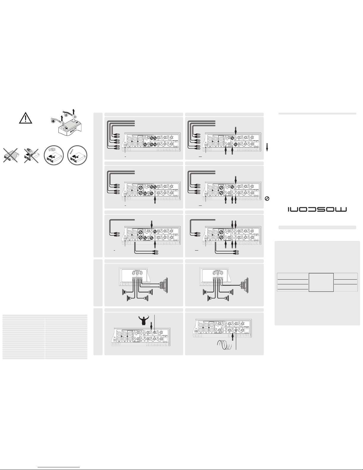
USE THIS SWITCH for this configurationDO NOT USE THIS SWITCH for this configuration
INPUT CONNECTI ONS
MANUALE D’USO
SICUREZZA
GARANZIA
GEBRAUCHSANWEISUNG
SICHERHEITSHINWEISSE
GARANTIEKARTE
OWNER’S MANUAL
WARNINGS
WARRANTY CARD
IMPORTANTE: LEGGETE ATTENTAMENTE QUESTO LIBRETTO D’USO AL FINE
DI FAMILI ARIZZA RE CON TUTTI I CONT ROLLI E LE FUNZ IONI. E’
INDISPENSABILE OSSERVARNE TUTTE LE INDICAZIONI, AFFINCHÉ POSSA
ESSERE GARANTITA LA SICUREZZA DI CHI OPERA L’INSTALLAZIONE E DI CHI
UTILIZZA IL PRODOTTO.
WICHTIG: LESEN SIE DIESE GEBRAUCHSANLEITUNG GENAU DURCH, UM SICH
SELBST MIT ALL DEN BEDIENTEILEN UND FUNKTIONEN DIESES PRODUKTS
VERTRAUT ZU MACHEN. BEFOLGEN SIE ALLE HINWEISE, DAMIT DIE
SICHERHEIT DER INSTALLATION UND DES GEBRAUCHS DES PRODUKTS
GEWÄHRLEISTET IST.
IMPORTANT: CAREFULLY READ THIS MANUAL TO FAMILIARIZE YOURSELF
WITH ALL THE CONTROLS AND FUNCTIONS OF THIS PRODUCT. FOLLOW ALL
NOTICES TO ENSURE THE SAFETY OF THOSE INSTALLING AND USING THE
PRODUCT.
Rev. 1.0 2015/12
-20 ~ 70°C
10 ~ 90%
Amplifier
DC-DC converter typology
Overall efficiency
External fuse
Autosense power-on
Stereo power RMS @4Ω
Low level + High level input sensitivity range
Power supply voltage
LP or HP filter frequency range
Unregulated – Push Pull
ONE 70.6
2 x 30A
in High Level mode only
>60%
70W x 6
10 - 16V
Front 45 ÷ 225Hz - Rear 20 ÷ 225Hz - Sub 45 ÷ 225Hz
0.35 ÷ 16V
Low level & High level input
Remote control (optional)
RCA
Modular jack
Weight
Color and finishing
2.7Kg
Black powder coating
LP and HP filter slope 12 dB/Oct
Stereo + Bridge power RMS @4Ω
70W x 4 + 230 x 1
Stereo power RMS @2Ω 100W x 6
Dimensions
310x200x50mm
TECHNICAL SPECIFICATIONS
Onboard crossover filter configuration
ON - OFF (Front HP - Rear HP or LP - Sub LP)
Bridge power RMS @4Ω
200W x 3
Onboard specific features FSA (Front section) - PHASE SHIFT (Sub section)
MINIMUM CAPABILITY IMPEDANCE: 2 OHM IN STEREO MODE; 4 OHM IN BRIDGE MODE
OUTPUT CONNECTIONS
REM CONNECTION
IS REQUIRED
REM CONNECTION
NOT REQUIRED
FROM
PRE-OUT
FROM
SPEAKER-OUT
2 STEREO LOW LEVEL SIGNAL INPUT (mixed subwoofer input)
3 STEREO LOW LEVEL SIGNAL INPUT
2 STEREO HIGH LEVEL SIGNAL INPUT (mixed subwoofer input)
3 STEREO HIGH LEVEL SIGNAL INPUT
1 STEREO HIGH LEVEL SIGNAL INPUT (mixed subwoofer input)1 STEREO LOW LEVEL SIGNAL INPUT (mixed subwoofer input)
REM CONNECTION
IS REQUIRED
FROM
PRE-OUT
FROM
SPEAKER-OUT
REM CONNECTION
NOT REQUIRED
REM CONNECTION
IS REQUIRED
FROM
PRE-OUT
BY-PASS
to an external power amplifier
(LOW LEVEL SIGNAL)
FROM
SPEAKER-OUT
BY-PASS
to an external power amplifier
(HIGH LEVEL SIGNAL)
REM CONNECTION
NOT REQUIRED
RUGULATION
Ruotare lentamente il potenziometro per modellare
opportunamente la scena sonora
Drehen Sie langsam am Potentiometer,
bis die Bühne in der gewünschten Position ist
Turn slowly the potentiometer
being careful to deformation
of the acoustic scene
FSA - FRONT SECTION PHASE SHIFT - SUB SECTION
Ruotare lentamente il potenziometro per
regolare il ritardo di fase
Drehen Sie langsam am Potentiometer,
bis die Phase in der gewünschten Position ist
Turn slowly the potentiometer
to control the phase shift
3 STEREO OUTPUT 2 STEREO OUTPUT + 1 MONO BRIDGED OUTPUT
DUAL VOICE COIL
MINIMUM CAPABILITY IMPEDANCE: 2 OHM IN STEREO MODE; 4 OHM IN BRIDGE MODE
SINGLE VOICE COIL
FOR THE PROPER FUNCTIONING OF FSA ALWAYS CONNECT
THE CHANNEL Ch1 TO THE DRIVER'S SIDE OF THE CAR
(LEFT FOR LHD CARS, RIGHT FOR RHD CARS)
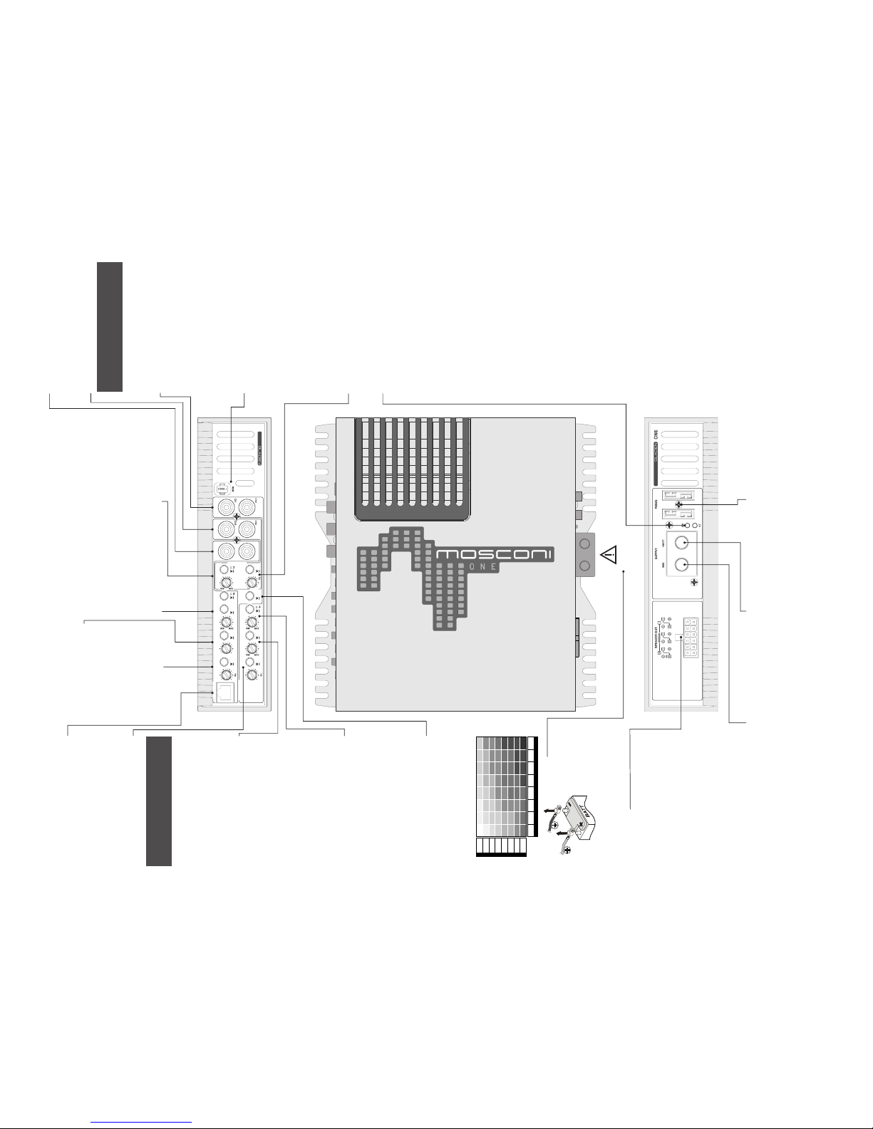
Ch2 Ch3 Ch4 Ch5 Ch6
FRONT REAR SUB
ONE 70.6
RTC
LEVEL LEVEL
LEVEL
LP FILTER
0
PHASE
DEG
180
HP FILTER
INPUT
INPUT
INPUT
ON
OFF
ON
OFF
FSAFILTER
LP
HP
RCA
F mix R
SUB
ON
OFF
ON
OFF
SUBFRONT REAR
Ch6
Ch5
RCA
F+R
F/R
2254522545
225
SUB SECTION
FRONT SECTION
REAR SECTION
FUSIBILE
Procedere alla sostituzione del fusibile assicurandosi che
la sorgente sia spenta e la batteria scollegata.
Togliere il fusibile bruciato e sostituirlo con uno dello stesso
tipo e di pari portata (stessa corrente massima).
SICHERUNGEN
Vor dem Austausch der Sicherung
muss das Radio abgeschaltet sein und
die Batterie abgeklemmt werden.
Entfernen Sie die defekte
Sicherung und ersetzen Sie diese mit
einer Sicherung der gleichen Größe
FUSE
Before replacing the fuse, power off the audio source
and then disconnect the battery.
Remove the blown fuse and replace it with the same
model and rating (same maximum amp)
NEGATIVO DI ALIMENTAZIONE
Collegare saldamente il morsetto ad un punto metallico
della vettura ripulito da residui, utilizzando un cavo il più
corto possibile e opportunamente terminato.
MASSE (MINUS) ANSCHLUSS
Verbinden Sie den „SUPPLY - “ Anschluss der Endstufe
mit der Fahrzeugkarosserie. Achten Sie darauf, dass die
Kontaktfläche sauber, trocken und unlackiert ist! Benützen
Sie ein möglichst kurzes Verbindungskabel
NEGATIVE POWER CONNETION
Securely connect the clamp to a metallic part of the frame
or chassis of the vehicle. Strip the paint and debris, and
use the shortest possible cable with the proper terminal.
POSITIVO DI ALIMENTAZIONE
Collegare il morsetto al polo Positivo della batteria
utilizzando un cavo il più corto possibile e opportunamente
terminato.
Si consiglia l’utilizzo di un fusibile esterno il più vicino
possibile alla batteria
12V (PLUS) ANSCHLUSS
Verbinden
Sie den „SUPPLY +“ Anschluss der Endstufe mit dem
Pluspol der Fahrzeugbatterie. Verwenden Sie hierfür ein
möglichst kurzes Kabel mit einem ausreichendem
Querschnitt. Achtung: Benützen Sie unbedingt eine externe
Sicherung (optional). Die Größe muss entsprechend dem
Kabelquerschnitt sein und befestigen Sie diese so nah wie
möglich am Pluspol der Fahrzeugbatterie.
POSITIVE POWER CONNECTION
Securely Connect
the clamp to the positive lead of the battery. Use the
shortest possible cable with the proper terminal. We
recommend using an external fuse as close as possible to
the battery.
CROSS-OVER FRONT (SOLO PASSA ALTO)
Attivare il filtro premendo il pulsante
Regolare la frequenza di taglio
del filtro tramite il potenziometro
FREQUENZWEICHE VORNE (NUR HOCH-PASS)
Durch Drücken des Schalters aktivieren Sie die Weiche.
Die Trennfrequenz wird über den Regler eingestellt
X-OVER FRONT (ONLY HP)
Activate the filter by pushing the button
Control the cut-off frequency of the filter by using the potentiometer (knob)
12V
FSA
Attivare il controllo premendo il pulsante
Regolare il fuoco dell’immagine sonora usando il potenziometro
FSA
Durch Drücken des Schalters aktivieren Sie den Phase Shift Adjustor.
Drehen Sie solange am Regler, bis Sie eine Einstellung gefunden haben,
die für Sie den besten Bühneneindruck (Mitte) hinterlässt. WICHTIG: Es
darf weder vorne/hinten, noch links/rechts, weder am Eingang noch am
Ausgang der G_one verdreht sein, da der FSA nur den vorderen, linken
Kanal beeinflusst und somit der FSA falsch arbeiten würde!
FSA
Activate the control by pushing the button
Adjust the focus of the stage image by using the potentiometer (knob)
CONTROLLO INGRESSI
Selezionare alto o basso livello di ingresso a
seconda dell’uscita utilizzata dell’autoradio
Regolare Impostare la sensibilità d’ingresso
dell’amplificatore perché si adatti al livello del
segnale generato dalla sorgente.
Consultare il manuale di uso della sorgente
EINGANGSMODUS
Wählen Sie „HI“ LEVEL, wenn Sie ein
Lautsprechersignal anschließen wollen (schon
verstärktes Signal vom Radio).
Wählen Sie „ LO“ LEVEL, wenn Sie ein
unverstärktes Signal anschließen wollen
(Vorverstärkerausgang (Cinch/Mini-Iso) vom
Radio/Prozessor).
Drehen Sie am „VOLT“ Regler um den Verstärker
Ihrem Radio/Prozessor bzgl. der Lautstärke
anzupassen
INPUT CONTROL
Select the hi-low input voltage concerning the
source output level
Adjust the sensitivity of the amplifier to the input
signal to adapt to the level of the audio source.
Consult the manual of the audio source.
CONTROLLO INGRESSI
Selezionare alto o basso livello di ingresso a seconda
dell’uscita utilizzata dell’autoradio
Premere il pulsante per selezionare come segnali di ingresso
il missaggio dei segnali FRONT e REAR
Regolare Impostare la sensibilità d’ingresso
dell’amplificatore perché si adatti al livello del segnale
generato dalla sorgente.
Consultare il manuale di uso della sorgente
EINGANGSMODUS
Wählen Sie „HI“ LEVEL, wenn Sie ein Lautsprechersignal
anschließen wollen (schon verstärktes Signal vom Radio).
Sie „ LO“ LEVEL, wenn Sie ein unverstärktes Signal
anschließen wollen (Vorverstärkerausgang (Cinch/Mini-Iso)
vom Radio/Prozessor).
Wählen wenn das Subwoofer-Eingangssignal aus dem MIX-
Signal von F (FRONT) & R (REAR) generiert werden soll.
Drehen Sie am „VOLT“ Regler um den Verstärker Ihrem
Radio/Prozessor bzgl. der Lautstärke anzupassen
INPUT CONTROL
Select the hi low input voltage
Activate when the subwoofer output signal should be
generated from the MIX signal of F (FRONT) & R (REAR).
Adjust
the sensitivity of the amplifier to the input signal to adapt to
the level of the audio source.
Consult the manual of the audio source.
LED
VERDE: l'amplificatore è in funzione.
Possibili cause in assenza di suono:
1. Il sistema di altoparlanti non è ben collegato o è danneggiato.
2. I cavi di segnale provenienti dalla sorgente sono scollegati o
danneggiati.
3. Il segnale proveniente dalla sorgente è assente o inadeguato.
4. E’ in corso la sequenza di accensione.
5. La temperatura dell’amplificatore ha raggiunto la soglia di sicurezza.
6. Si è verificato un sovraccarico di corrente nel circuito degli altoparlanti.
Rimedio:
1. Verificare/ripristinare i collegamenti e/o sostituire gli altoparlanti
danneggiati.
2. Verificare/ripristinare i collegamenti provenienti dalla sorgente.
3. Regolare adeguatamente la sorgente seguendo le istruzioni fornite dal
costruttore.
4. Attendere tre secondi, l’amplificatore passerà al normale funzionamento.
5. Attendere che la temperatura diminuisca.
6. Eliminare la causa del sovraccarico.
ROSSO: l'amplificatore è acceso ma non in funzione.
Spegnere e riaccendere l'amplificatore per verificarne il
funzionamento
Possibili cause:
1. Il circuito di alimentazione è inadeguato.
2. Il fusibile è bruciato.
3. La tensione presente ai morsetti d’alimentazione dell’amplificatore è
inferiore a 7 VDC.
4. L’amplificatore è guasto.
Rimedio:
1. Verificare e ripristinare i cavi e la solidità dei contatti nel circuito di
alimentazione.
2. Sostituire il fusibile.
3. Ricaricare o sostituire la batteria.
4. Rivolgersi al punto vendita per attivare la procedura di Assistenza
Tecnica
LED
GRÜN: der Verstärker ist in Betrieb
Mögliche Gründe wenn kein Ton hörbar ist:
1) Das Lautsprechersystem ist nicht vorschriftsmäßig
verbunden oder ist beschädigt
2) Die Signalkabel des Radios sind nicht sachgemäß
verbunden oder beschädigt
3) Das Signal des Radios ist nicht vorhanden oder
unzureichend
4) Der Verstärker startet gerade
5) Die Temperatur hat den Sicherheits-Grenzbereich erreicht
6) Momentane Überlastung der Lautsprechereinheit
Abhilfe:
1) Überprüfen/erneuern Sie die Verkabelung und/oder
ersetzen sie beschädigte Lautsprecher
2) Überprüfen/erneuern Sie die Verkabelung des Radios
3) Passen sie das Radio sachgemäß mit Hilfe der
Herstellerempfehlung an
4) Warten Sie 3 Sekunden, der Verstärker wird wider in den
normalen Betrieb Übergehen
5) Warten Sie, bis die Temperatur sinkt
6) Beheben Sie den Grund der Überlastung
ROT: der Verstärker ist eingeschaltet,
funktioniert aber nicht.
Mögliche Gründe:
1) Die Stromversorgung ist unzureichend
2) Die Sicherung ist durchgebrannt
3) Die Stromversorgung ist unter 7 Volt
4) Der Verstärker ist defekt.
Abhilfe:
1) Überprüfen/erneuern Sie die Verkabelung und die
Kontakte des Stromkreislaufs
2) Tauschen Sie die Sicherung aus
3) Laden Sie die Batterie auf oder ersetzen Sie die
Fahrzeugbatterie
4) Kontaktieren Sie einen autorisierten Vertriebspartner, um
die technische Betreuung einzuleiten
LED
GREEN: the amplifier is in operation
Possible causes for lack of sound:
1) The loudspeaker system is not connected properly or is damaged
2) The signal cables from the audio source are not properly connected or
damaged
3) The signal from the audio source is absent or inadequate
4) The amplifier is powering up
5) The temperature has reached the safety threshold
6) Current overload in the loudspeaker circuit
Remedy
1) Verify/restore the connection and/or replace the damaged loudspeakers
2) Verify/restore the connection from the audio source
3) Properly adjust the audio source following the manufacturer's
recommendations
4) Wait 3 seconds, the amplifier will switch to normal operation
5) Wait for the temperature to decrease
6) Remove the cause of the overload
RED: the amplifier is powered on but is not functioning. Cycle the
power to verify proper operation.
Possible causes:
1) The power supply is inadequate
2) The fuse has blown
3) The power voltage is below 7 VDC
4) The amplifier is malfunctioning
Remedy:
1) Verify and restore the connections and the contacts of the power circuit
2) Replace the fuse
3) Recharge or replace the vehicle's battery
4) Contact an authorized reseller to initiate the procedure for Technical
Assistance
USCITE AGLI ALTOPARLANTI
Front
Collegare gli altoparlanti ai morsetti Ch1 e Ch2 per riprodurre i segnali
collegati rispettivamente agli RCA Ch1 e Ch2
Collegare gli altoparlanti ai morsetti BRIDGE per riprodurre il missaggio dei
segnali collegati agli RCA Ch1 e Ch2
Rear
Collegare gli altoparlanti ai morsetti Ch3 e Ch4 per riprodurre i segnali
collegati rispettivamente agli RCA Ch3 e Ch4
Collegare gli altoparlanti ai morsetti BRIDGE per riprodurre il missaggio dei
segnali collegati agli RCA Ch3 e Ch4
Sub
Collegare gli altoparlanti ai morsetti Ch5 e Ch6 per riprodurre i segnali
collegati rispettivamente agli RCA Ch5 e Ch6
Collegare gli altoparlanti ai morsetti BRIDGE per riprodurre il missaggio dei
segnali collegati agli RCA Ch5 e Ch6
LAUTSPECHERANSCHLUSS
Front
Schließen Sie den linken und rechten Lautsprecher (bzw. Weiche) für vorne
an „Ch1“ und „Ch2“ an. Wünschen Sie einen gebrückten Monoausgang
verwenden Sie den „BRIDGE“ Ausgang.
Rear
Schließen Sie den linken und rechten Lautsprecher (bzw. Weiche) für
hinten an „Ch3“ und „Ch4“ an. Wünschen Sie einen gebrückten
Monoausgang verwenden Sie den „BRIDGE“ Ausgang.
Sub
Schließen Sie den linken und rechten Lautsprecher (bzw. Weiche) für
hinten an „Ch5“ und „Ch6“ an. Wünschen Sie einen gebrückten
Monoausgang verwenden Sie den „BRIDGE“ Ausgang.
SPEAKER CONNECTIO
Front
Connect the speakers to the Ch1 and Ch2 terminals to reproduce the audio
input in the RCA Ch1 and Ch2 respectively.
Connect the speakers to the BRIDGE terminals to reproduce a mixed
signal from the RCA Ch1 and Ch2
Rear
Connect the speakers to the Ch3 and Ch4 terminals to reproduce the audio
input in the RCA Ch3 and Ch4 respectively.
Connect the speakers to the BRIDGE terminals to reproduce a mixed
signal from the RCA Ch3 and Ch4
Sub
Connect the speakers to the Ch5 and Ch6 terminals to reproduce the audio
input in the RCA Ch5 and Ch6 respectively.
Connect the speakers to the BRIDGE terminals to reproduce a mixed
signal from the RCACh5 and Ch6
WARNING!
Use power cables with a gauge that is appropriate to the current load
and to the length of the cable. The table in this manual indicates the
minimum gauge for safe use. Whenever possible, use the largest
gauge available.
14/2 12/4
12/4 10/6
10/6
10/6 10/612/4 8/9 8/9 8/9
8/9 8/9
8/9 8/9
8/9 8/9
6/14
6/146/14
6/14 6/14
6/14
6/14
6/14
6/14
6/14
4/21
4/21
4/21
4/214/214/21
4/21
4/21 4/21 4/21
4/21 4/21
4/21
4/21
2/34 2/34 2/34
2/34
2/34 2/34
2/34 2/34
2/34 2/34 2/34
2/34
2/34 2/34
0/54 0/54
0/54
0/54
0/54 0/54
0/54
0/54
0-1.2 1.2-2.1 2.1-3.1 3.1-4.0 4.0-4.9 4.9-5.8 5.8-6.7
0-20
20-35
35-50
50-65
65-85
85-105
105-125
125-150
6.7-8.5
CURRENT (A)
LENGTH (m.)
2
MIN. SECTION (AWG/mm)
WARNING!
DISCONNECT THE
BATTERY LEADS
BEFORE
INSTALLATION,
MAINTENANCE OR
REMOVAL.
INGRESSO SEGNALE RCA
Canali FRONT Ch1 & Ch2
CINCH SIGNAL EINGANG „FRONT“
Linker und rechter Eingang für vorne
RCA SIGNAL INPUT
FRONT Channels Ch1 & Ch2
CROSS-OVER REAR
Regolare la frequenza di taglio
del filtro tramite il potenziometro
Selezionare HP per filtro passa alto
LP per filtro passa basso
FREQEUNZWEICHE HINTEN:
Durch Die Trennfrequenz wird über den gleichen Regler für
Hochpass und Tiefpass eingestellt.
Wählen Sie HP für einen Hochpassfilter.
Sie TP für einen Tiefpassfilter.
X-OVER REAR
Control the cut-off frequency of the filter by using the
potentiometer (knob)
Select HP for an hi-pass filter
LP for a low-pass filter
CROSS-OVER SUB (SOLO PASSA BASSO)
Attivare il filtro premendo il pulsante
Regolare la frequenza di taglio
del filtro tramite il potenziometro
FREQUENZWEICHE SUB (NUR TIEFPASS)
Durch Drücken des Schalters aktivieren Sie die Weiche.
Die Trennfrequenz wird über den Regler eingestellt
X-OVER SUB (LP ONLY)
Activate the filter by pushing the button
Control the cut-off frequency of the filter by using the
potentiometer (knob)
CONTROLLO INGRESSI
Selezionare alto o basso livello di ingresso a seconda dell’uscita utilizzata
dell’autoradio
Regolare Impostare la sensibilità d’ingresso dell’amplificatore perché si
adatti al livello del segnale generato dalla sorgente.
Consultare il manuale di uso della sorgente
EINGANGSMODUS
Wählen Sie „HI“ LEVEL, wenn Sie ein Lautsprechersignal anschließen
wollen (schon verstärktes Signal vom Radio).
Wählen Sie „ LO“ LEVEL, wenn Sie ein unverstärktes Signal anschließen
wollen (Vorverstärkerausgang (Cinch/Mini-Iso) vom Radio/Prozessor).
Drehen Sie am „VOLT“ Regler um den Verstärker Ihrem Radio/Prozessor
bzgl. der Lautstärke anzupassen
INPUT CONTROL
Select the hi-low input voltage concerning the source output level
Adjust the sensitivity of the amplifier to the input signal to adapt to the level
of the audio source.
Consult the manual of the audio source.
BYPASS
Attivare per avere gli stessi segnali dei canali Ch1 e Ch2 rispettivamente
nei canali Ch3 e Ch4
Gli RCA Ch3 e Ch4 possono essere utilizzati come by-pass rispettivamente
degli RCA Ch1 e Ch2
BYPASS
Aktivieren wenn nur 2 Kanäle von der Audio Quelle zu Verfügung stehen.
RCA REAR ( ) wird im BYPASS verwendet.Ch3 & Ch4
BYPASS
Activate to repeat Ch1 and Ch2 signals to the Ch3 and Ch4 channels
respectively.
The RCA Ch3 and Ch4 can be used as bypass of RCA Ch1 and Ch2
respectively.
ACCENSIONE REMOTA
Collegare il terminale di accensione remota (+12V) della sorgente al
connettore FASTON dell’amplificatore utilizzando un cavetto
opportunamente terminato.
VERSTÄRKER REMOTE
Verbinden Sie den Remote-Eingang mit dem Remote-Ausgang des
Autoradios (12V Ausgang für Verstärker oder
automatische Antenne)
REMOTE POWER CONTROL
Connect the remote power terminal (+12V) of the source to the FASTON
connector of the amplifier using a properly terminated cable.
CONTROLLO REMOTO (opzionale)
Collegare il terminale del controllo remoto (opzionale) al connettore
dell’amplificatore
PEGELFERNBEDIENUNG:
Verbinden Sie die Leitung der Pegelfernbedienung mit dieser Buchse
REMOTE CONTROL (optional)
Connect the remote control (optional) terminal to this connector
CONTROLLO DI FASE
Attivare il controllo premendo il pulsante
Regolare il ritardo di fase tramite il potenziometro
PHASENDREHER
Durch Drücken des Schalters aktivieren Sie den
Phasenregler.
Durch Drehen an dem Regler stellen Sie die gewünschte
Phase ein
PHASE CONTROL
Activate the control by pushing the button
Control the phase shift by using the potentiometer (knob)
INGRESSO SEGNALE RCA
Canali REAR Ch3 & Ch4
CINCH SIGNAL EINGANG „REAR“
Linker und rechter Eingang für hinten
RCA SIGNAL INPUT
REAR Channels Ch3 & Ch4
INGRESSO SEGNALE RCA
Canali SUB Ch5 & Ch6
CINCH SIGNAL EINGANG „SUB“
Linker und rechter Eingang für subwoofer
RCA SIGNAL INPUT
SUB Channels Ch5 & Ch6
FOR THE PROPER FUNCTIONING OF FSA
ALWAYS CONNECT THE CHANNEL Ch1 TO THE
DRIVER'S SIDE OF THE CAR
(LEFT FOR LHD CARS, RIGHT FOR RHD CARS)
FOR THE PROPER FUNCTIONING OF FSA
ALWAYS CONNECT THE CHANNEL Ch1 TO THE
DRIVER'S SIDE OF THE CAR
(LEFT FOR LHD CARS, RIGHT FOR RHD CARS)
 Loading...