

2 STEREO OUTPUT
W
W
W
W
V
Hz
dB/Oct
Hz
dB/Oct
A
mm
Stereopower RMS @4ohm
Stereopower RMS @2ohm
Bridgepower RMS @4ohm
Bridgepower RMS @2ohm
Inputsensitivity range
Highpass filter range (switchable)
Highpass filter slope
Lowpass filter range (switchable)
Lowpass filter slope
Bandpass filter
Internalfuse
Dimensions
AS100.2
2x 100
2x 160
1x 320
1x 500
0.2÷ 5
20÷ 175
12
50÷ 300
12
Available
40
215x 200 x 50
AS200.2
2x 200
2x 320
1x 640
1x 1000
0.2÷ 5
20÷ 175
12
50÷ 300
12
Available
80
350x 200 x 50
AS300.2
2x 300
2x 550
1x 1100
1x 1800
0.2÷5
20÷ 175
12
50÷ 300
12
Available
150
590x 200 x 50
AS100.4
4x 100
4x 155
2x 310
2x 480
0.2÷ 5
20÷175
12
50÷300
12
Available
80
350x 200 x 50
AS200.4
4x 200
4x 320
2x 640
2x 950
0.2÷ 5
20÷ 175
12
50÷ 300
12
Available
150
590x 200 x 50
OWNER’S MANUAL
WARRANTY CARD
WARNINGS
AUDIO SYSTEM AS SERIES
MOSCONI reserves the right to modify or improve the products described here without notice. The availability of the displayed
productsmay vary.Products described inthis MANUAL area portion ofall MOSCONI products.All trademarks mentionedare used
fordescriptive purposes and all rights arereserved by their respective owners. The totalor partial reproduction of this MANUALis
prohibited.
Ch1
Ch2
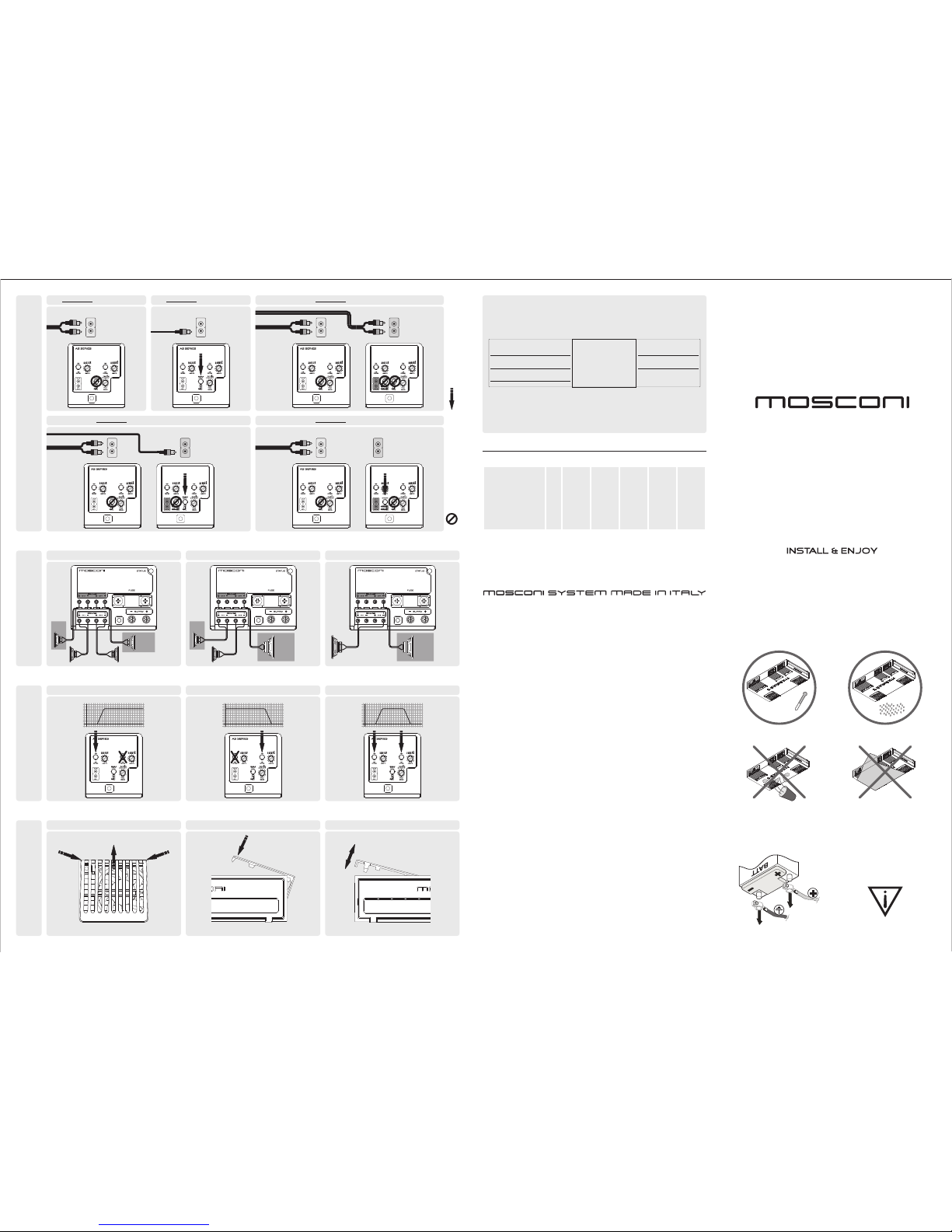
2CHAMPLIFIER - 1 STEREO SIGNAL 2CHAMPLIFIER - 1 MONO SIGNAL
Ch1
Ch2
The Ch2 RCAmay be
used as a by-pass
of the Ch1 RCA
DO NOTUSE THIS SWITCH for this configuration
USETHIS SWITCH for this configuration
Ch1
Ch2
4CHAMPLIFIER - 2 STEREO SIGNAL
Ch3
Ch4
CONNECTING INPUT
CONNECTING SPEAKERS
Ch1
Ch2
Ch3
Ch4
Ch1
Ch2
Ch3
Ch4
4CHAMPLIFIER - 1 STEREO + 1 MONOSIGNAL SIGNAL 4CHAMPLIFIER - 1 STEREO SIGNAL
The Ch4 RCAmay be
used as a by-pass
of the Ch3 RCA
The Ch3 e Ch4 RCA
may be used as a
by-pass of Ch1 and Ch2 RCA
respectively
1 STEREO OUTPUT+ 1 MONO BRIDGED OUTPUT 2 MONO BRIDGED OUTPUT
HIGH PASSFILTER
FILTER SELECTION
LOW PASSFILTER BAND PASSFILTER
REMOVING GRIDS
GRIDS AND COVERS
MOUNTING GRIDS USINGTHE COVERS
WARRANTY
WARRANTYCONDITIONS
COMPLETEALL SECTIONSAND RETURN THISDOCUMENT ALONG WITHA) THE
PRODUCTTO REPAIRAND B)THE ORIGINALDATED PURCHASERECEIPT
MOS extends a warranty to MOSCONI products for 24 months from the date of the original purchase as
declared in the appropriate box and in the original purchase receipt. Enclose the dated purchase receipt
whensending theproduct for returnor repairto the authorizeddealer.
Theserial numberof this certificatemust correspondto the onestamped onthe returned product.
MOSis notresponsible for damagesor injurycaused by improperinstallation oroperation of theproduct.
Name
Address
e-mail & Phone
Client Autorized Dealer
Model
Serial Number
Product
MINIMUM CAPABILITYIMPEDANCE: 1OHM IN STEREO MODE; 2OHM IN BRIDGE MODE
WARNING!CAUTION:
IN CASE OF TROUBLE IMMEDIATELYDISCONTINUE
USE. Failure to comply may cause injury or damage the
product. For repair please contact an authorized
MOSCONIdealer.
DO NOT DISASSEMBLE OR MODIFY THE PRODUCT:
This action mayresult in accidents, fire or electric shock.
Any alteration or modificationto the product immediately
voidsany expressedor implied warranty.
THE INSTALLATION AND CONNECTION OF THE
PRODUCT SHOULD BE PERFORMED BY QUALIFIED
PERSONNEL. The installation and connection of the
product require specific technical background and
experience. . For safety reasons, always contact an
authorizeddealer toinstall the productin acorrect way.
DONOT INSTALLIN AREASPARTICULARYHUMID OR
DUSTY.Avoid installing the product in areas excessively
humid or dusty. Presence of humidity or dust inside the
productcan causemalfunction.
DO NOT INSTALL NEXT TO HEAT SENSITIVE
SURFACES. The amplifier may reach temperatures in
excess of 80°C (176°F) and contact with heat sensitive
surfaces may cause a fire hazard and damage to the
surface.
WHILE DRILLING HOLES, DO NOT DAMAGE TUBING
AND CABLES. Whiledrilling holes in your vehicle during
installation, pay close attention to avoid damaging,
blockingor contact with:tubing, thefuel lines, thefuel tank
and electrical cables. Failure to follow these precautions
willpose afire hazard anddamages.
DO NOT OBSTRUCT VENTS OR HEAT SINKING
PANELS. Blocking vents or heat sinking panels may
cause increased temperatures inside the amplifier. This
maycause afire hazard.
USE THIS PRODUCT EXCLUSIVELY IN VEHICLES
WITH 12V POWER. Using the product with electrical
power other than 12V may cause fires, electric shock or
otheraccidents.
DISCONNECT THE NEGATIVE (GROUND) BATTERY
LEAD BEFORECONNECTING THE PRODUCT. Failure
to do so may cause electric shock or other damage and
injurydue toshort circuit.
ENSURE PROPER CONNECTIONS. To avoid fire
hazard and damage to theproduct, use cables of proper
gauge and pay close attention to the polarity of the
connections.
AVOIDTANGLING THE CABLES TO VEHICLE PARTS.
Make properconnections by following the instructions so
that the cables do not interfere with proper vehicle
operation. Cables that tangle with steering components,
gear lever, brakepedals, etcmay be dangerous.
LAYOUT THE CABLES TO ENSURE THAT THEY ARE
NOT BENT OR COMPRESSED BY SHARP METAL
EDGES.Toavoid damaging orbending thecables, lay out
the cables far from moving parts (such as the seat rails)
andfrom sharp or pointy vehicleparts. If the cablesare to
pass througha hole in a metal sheet,use a rubber ring to
ensurethat the cable insulation won'tbe cut by anysharp
edge.
TO ESTABLISH A GROUND CONNECTION DO NOT
USE BOLTS THAT BELONG TO THE STEERING OR
BRAKING SYSTEM. NEVERuse bolts from the steering
or brakingsystem (or any other safetysystem) or the fuel
tankto establish aground connection. Usingany of these
parts may impair your ability to control the vehicle and
causeaccidents, fireor other damage.
USE FUSES WITH ADEQUATE AMP RATING.
Otherwisethere maybe fires orelectric shock.
USE THE CORRECT ACCESSORY PARTS AND
FOLLOW THE INSTALLATION INSTRUCTIONS. Be
sure to use only specified accessory parts. Using other
components may damage the product or result in
improper installation. Components may not be
connectedsecurely andcause malfunction ordanger.
DO NOT OPERATE THE PRODUCT IN WAYS THAT
MAY DISTRACT YOUR ATTENTION FROM DRIVING.
Any operation that requires continued attention must be
done when the vehicle is at full stop. Always stop the
vehicle in a safe area when performing such operations.
Failureto doso may causeaccidents.
MAINTAIN THE VOLUME AT LEVELS THAT ALLOW
EXTERNALNOISES TO BEAUDIBLE WHILE DRIVING.
Excessive volume levels, capable of blocking the sound
of emergency vehicles, rail crossings, etc, may be
dangerous and cause accidents. Furthermore, listening
to audio at high volume inside a vehicle may cause
damageto yourhearing.
IMPORTANT: CAREFULLY READ THIS MANUAL TO FAMILIARIZE YOURSELF WITH ALL THE CONTROLS AND FUNCTIONS OF THIS PRODUCT. FOLLOW ALL NOTICES TO
ENSURETHE SAFETY OFTHOSE INSTALLINGAND USINGTHE PRODUCT.
0 ~ 60°C
10 ~ 90%
WARNING!
DISCONNECT THE BATTERYLEADS
BEFORE INSTALLATION,MAINTENANCE
OR REMOVAL.
12V
WARNING!
USE ONLYIN VEHICLES WITH A 12 VOLT
NEGATIVEGROUND
MINIMUM CAPABILITYIMPEDANCE: 1OHM IN STEREO MODE; 2OHM IN BRIDGE MODE
isa brand of mos company di ivanmosconi - loc. ghilardino 61034 fossombrone (pu) italia - www.mos-hta.it
caratteristichetecniche
4Ch4Ch
4Ch4Ch
4Ch
FUSIBILE DI
PROTEZIONE
AS 100.2 40A
AS 200.2 80A
AS 300.2 150A
AS 100.4 80A
AS 200.4 150A
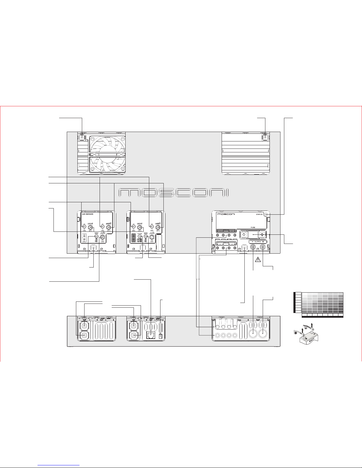
Before replacing the fuse, power off
the audio source and then
disconnect the battery.
Remove the blown fuse and replace
it with the same model and rating
(same maximum amp)
FASTENING HOLES
Use the screws provided in the package
or screws of 4mm diameter. Tighten bolts
to a maximum of 5 Nm torque.
NEGATIVEPOWER
CONNETION
Securely connect the
clamp to a metallic part
of the frame or chassis
of the vehicle. Strip the
paint and debris, and
use the shortest
possible cable with the
proper terminal.
POSITIVE POWER
CONNECTION
Connect the clamp to
the positive lead of the
battery.Use the
shortest possible cable
with the proper
terminal. We
recommend using an
external fuse as close
as possible to the
battery.
LOW PASSFILTER
Activate
Control
the low pass filter by pushing
the button
the cut-off frequency of the low-
pass filter by using the
potentiometer (knob)
ATTENTION!
Use power cables with a gauge that is appropriate to the
current load and to the length of the cable. The table in this
manual indicates the minimum gauge for safe use. Whenever
possible, use the largest gauge available.
14/2 12/4
12/4 10/6
10/6
10/6 10/612/4 8/9 8/9 8/9
8/9 8/9
8/9 8/9
8/9 8/9
6/14
6/146/14
6/14 6/14
6/14
6/14
6/14
6/14
6/14
4/21
4/21
4/21
4/214/214/21
4/21
4/21 4/21 4/21
4/21 4/21
4/21
4/21
2/34 2/34 2/34
2/34
2/34 2/34
2/34 2/34
2/34 2/34 2/34
2/34
2/34 2/34
0/54 0/54
0/54
0/54
0/54 0/54
0/54
0/54
0-1.2 1.2-2.1 2.1-3.1 3.1-4.0 4.0-4.9 4.9-5.8 5.8-6.7
0-20
20-35
35-50
50-65
65-85
85-105
105-125
125-150
6.7-8.5
CURRENT(A)
LENGTH(m.)
MIN. SECTION (AWG/mm)
2
RCA SIGNAL INPUT
Channel 1
Channel 2
Channel 3
Channel 4
12V
HIGH PASSFILTER
Activate
Control
the high pass filter by pushing
the button
the cut-off frequency of the
high-pass filter by using the
potentiometer (knob)
BAND PASSFILTER
Activate
Control
both filters to get a band pass
filter
the cut-off frequencies by
using both potentiometers
(knobs)
FASTENING HOLES
Use the screws provided in the package
or screws of 4mm diameter. Tighten bolts
to a maximum of 5 Nm torque.
SINGLE INPUT
Activate
NOTE: use this function only if
there is a single input connected
this button to have the same channel
ch3 signal in channel ch4.
The RCA ch4 may be used as a
channel ch3 bypass.
SINGLE INPUT
Activate
NOTE: use this function only if
there is a single input connected
to the amplifier
this button to have the same channel
ch1 signal in channel ch2.
The RCA ch2 may be used as a
channel ch1 bypass.
FASTENING HOLES
Use the screws provided in the package
or screws of 4mm diameter. Tighten bolts
to a maximum of 5 Nm torque.
GAIN (SENS.)
Adjust
the sensitivity of the amplifier to the
input signal to adapt to the level of
the audio source.
Consult the manual of the audio
source.
BYPASS
Activate
to repeat ch1 and ch2 signals to the
ch3 and ch4 channels respectively.
The RCA of ch3 and ch4 can be used
as bypass of RCA of ch1 and ch2
respectively.
REMOTE POWER CONTROL
Connect the remote power terminal
(+12V) of the source to the FASTON
connector of the amplifier using a
properly terminated cable.
INDICATIONLIGHT
RED:
ORANGE:
YELLOW:
1) The loudspeaker system is not connected properly
or is damaged
2) The signal cables from the audio source are not
properly connected or damaged
3) The signal from the audio source is absent or
inadequate
1) Verify/restore the connection and/or replace the
damaged loudspeakers
2) Verify/restore the connection from the audio source
3) Properly adjust the audio source following the
manufacturer's recommendations
1) The amplifier is powering up
2) The temperature has reached the safety threshold
3) Current overload in the loudspeaker circuit
1) Wait 3 seconds, the amplifier will switch to normal
operation
2) Wait for the temperature to decrease
3) Remove the cause of the overload
1) The power supply is inadequate
2) The fuse has blown
3) The power voltage is below 7 VDC
4) The amplifier is malfunctioning
1) Verify and restore the connections and the contacts
of the power circuit
2) Replace the fuse
3) Recharge or replace the vehicle's battery
4) Contact an authorized reseller to initiate the
procedure for TechnicalAssistance
the amplifier is in operation
Possible causes for lack of sound:
Remedy
the amplifier is in protected mode. After 3
seconds the amplifier attempts to resume automatically
Possible causes:
Remedy:
the amplifier is powered on but is not
functioning.
Cycle the power to verify proper operation.
Possible causes:
Remedy:
REMOTE CONTROL (optional)
Connect
the remote control (optional) terminal
to this connector
SPEAKER CONNECTION
Connect
the speakers to the Ch1 and Ch2 terminals
to reproduce the audio input in the RCA ch1
and ch2 respectively.
Connect the speakers to the BRIDGE
terminals to reproduce a mixed signal from
the RCA ch1 and ch2
SPEAKER CONNECTION
Connect
the speakers to the Ch3 and Ch4 terminals
to reproduce the audio input in the RCA ch3
and ch4 respectively.
Connect the speakers to the BRIDGE
terminals to reproduce a mixed signal from
the RCA ch3 and ch4
FASTENING HOLES
Use the screws provided in the package or
screws of 4mm diameter. Tighten bolts to a
maximum of 5 Nm torque.
WARNING!
DISCONNECT THE
BATTERYLEADS
BEFORE
INSTALLATION,
MAINTENANCE OR
REMOVAL.
 Loading...