

Mosa YANMAR GE 35 YSX, YANMAR GE 45 YSX, YANMAR GE 35 YSX (350 l), YANMAR GE 35 YSX (SINGLEPHASE), YANMAR GE 45 YSX (350 l) Maintance Manual
Page 1
MADE IN ITALY
CF1CB0519003
“YANMAR”
GE 35 YSX
GE 45 YSX
• Gruppo Elettrogeno
• Generating Set
• Groupe Electrogene
• Grupos Electrógenos
• Stromerzeuger
• Grupo Gerador
• Генераторная Установка
• Stroomaggregaten
• Skupina generátoru
Codice
Code
Code
Codigo
Kodezahl
Código
Код
Code
Kód
Edizione
Edition
Édition
Edición
Ausgabe
Edição
Издание
Editie
Edice
05.2018
USE AND MAINTENANCE MANUAL
TRANSLATION OF THE ORIGINAL INSTRUCTIONS – ENGLISH
language
Page 2

Page 3

02/05/18 CF1CB051_EN
ENGLISH
ENGLISH
REV.0-05/18
INDEX
0. GENERAL INFORMATION
M1.1
INTRODUCTION
...................................................................................................................... PAG. 4
M1.4
CE MARK
................................................................................................................................ PAG. 5
M2
SYMBOLS AND SAFETY PRECAUTIONS
................................................................................... PAG. 6
M2.1
WARNINGS
............................................................................................................................. PAG. 7
M2.5
SAFETY RULES
....................................................................................................................... PAG. 8
1. GENERAL INFORMATION OF THE MACHINE
M0
DESCRIPTION OF THE MACHINE
.............................................................................................. PAG. 10
RECORDING DATA
................................................................................................................... PAG. 11
2. DISPLACEMENTS AND TRANSPORT
M3
MACHINE UNPACKING
............................................................................................................ PAG. 12
M4.2
TRANSPORT AND HANDLING
.................................................................................................. PAG. 13
3. INSTALLATION AND USE
M2.7
INSTALLATION
........................................................................................................................ PAG. 15
M2.6
INSTALLATION AND ADVICE
.................................................................................................... PAG. 16
M20
SET-UP FOR OPERATION DIESEL ENGINE
................................................................................ PAG.20
EARTHING
.............................................................................................................................. PAG. 22
M21
STARTING AND STOPPING
...................................................................................................... PAG. 23
M31
CONTROLS
............................................................................................................................. PAG. 24
M32
CONTROLS DESCRIPTION .......................................................................................................
PAG .25
M37...
USE AS A GENERATOR
............................................................................................................ PAG.26
M39.11
PROTECTION - EARTH LEAKAGE RELAY
.................................................................................. PAG. 29
M39.10
PROTECTION - ISOMETER
....................................................................................................... PAG. 30
M29.2
3-WAY VALVE FUEL SYSTEM KIT
............................................................................................. PAG. 31
M38.6
TCM35 REMOTE CONTROL
..................................................................................................... PAG. 32
5. MAINTENANCE
M40.2...
TROUBLE SHOOTING
.............................................................................................................. PAG. 33
M43
MAINTENANCE
....................................................................................................................... PAG. 35
M45
STORAGE AND CAST OFF
....................................................................................................... PAG. 38
6. TECHNICAL INFORMATIONS
M1.5...
TECHNICAL DATA
.................................................................................................................... PAG. 39
M2.7.1
DIMENSIONS
.......................................................................................................................... PAG. 42
3
Page 4

10/10/02 M1-1_EN
ENGLISH
ENGLISH
REV.0-10/02
M
1.1
INTRODUCTION
Dear Customer,
We wish to thank you for having bought a high quality set.
Our sections for Technical Service and Spare Parts will work at
best to help you if it were necessary.
To this purpose we advise you, for all control and overhaul
operations, to turn to the nearest authorized Service Centre,
where you will obtain a prompt and specialized intervention.
+ In case you do not prot on these Services and some arts
are replaced, please ask and be sure that are used exclusively original parts; this to guarantee that the performances
and the initial safety prescribed by the norms in force are
re-established.
+The use of non original spare parts will cancel immediately
any guarantee and Technical Service obligation.
NOTES ABOUT THE MANUAL
Before actioning the machine please read this manual attentively. Follow the instructions contained in it, in this way you will
avoid inconveniences due to negligence, mistakes or incorrect
maintenance. The manual is for qualied personnel, who knows
the rules: about safety and health, installation and use of sets
movable as well as xed.
You must remember that, in case you have difculties for use
or installation or others, our Technical Service is always at your
disposal for explanations or interventions.
The manual for Use Maintenance and Spare Parts is an integrant part of the product. It must be kept with care during all
the life of the product.
In case the machine and/or the set should be yielded to another
user, this manual must also given to him.
Do not damage it, do not take parts away, do not tear pages and
keep it in places protected from dampness and heat.
You must take into account that some gures contained in it
want only to identify the described parts and therefore might
not correspond to the machine in your possession.
INFORMATION OF GENERAL TYPE
In the envelope given together with the machine and/or set you
will nd: the manual for Use Maintenance and Spare Parts,
the manual for use of the engine and the tools (if included in
the equipment), the guarantee (in the countries where it is
prescribed by law).
+ NOTICE: the manufacturer, who keeps the faculty, apart
the essential characteristics of the model here described
and illustrated, to bring betterments and modications to
parts and accessories, without putting this manual uptodate
immediately.
The Manufacturer shall not be liable for ANY USE OF THE PRODUCT OTHER THAN THAT PRECISELY SPECIFIED IN THIS
MANUAL and is thus not liable for any risks which may occur as
a result of IMPROPER USE. The Company does not assume
any liability for any damage to persons, animals or property.
Our products are made in conformity with the safety norms in
force, for which it is advisable to use all these devices or information so that the use does not bring damage to persons or things.
While working it is advisable to keep to the personal safety
norms in force in the countries to which the product is destined
(clothing, work tools, etc.).
Do not modify for any motive parts of the machine (fastenings,
holes, electric or mechanical devices, others..) if not duly authorized in writing: the responsibility coming from any potential
intervention will fall on the executioner as in fact he becomes
maker of the machine.
4
Page 5
10/10/02 M1-4_EN
ENGLISH
ENGLISH
1
2
17
19
20
21
22
23
24
25
25
18
3
4
5
6
7
8
9
10
11
12
13
14
15
16
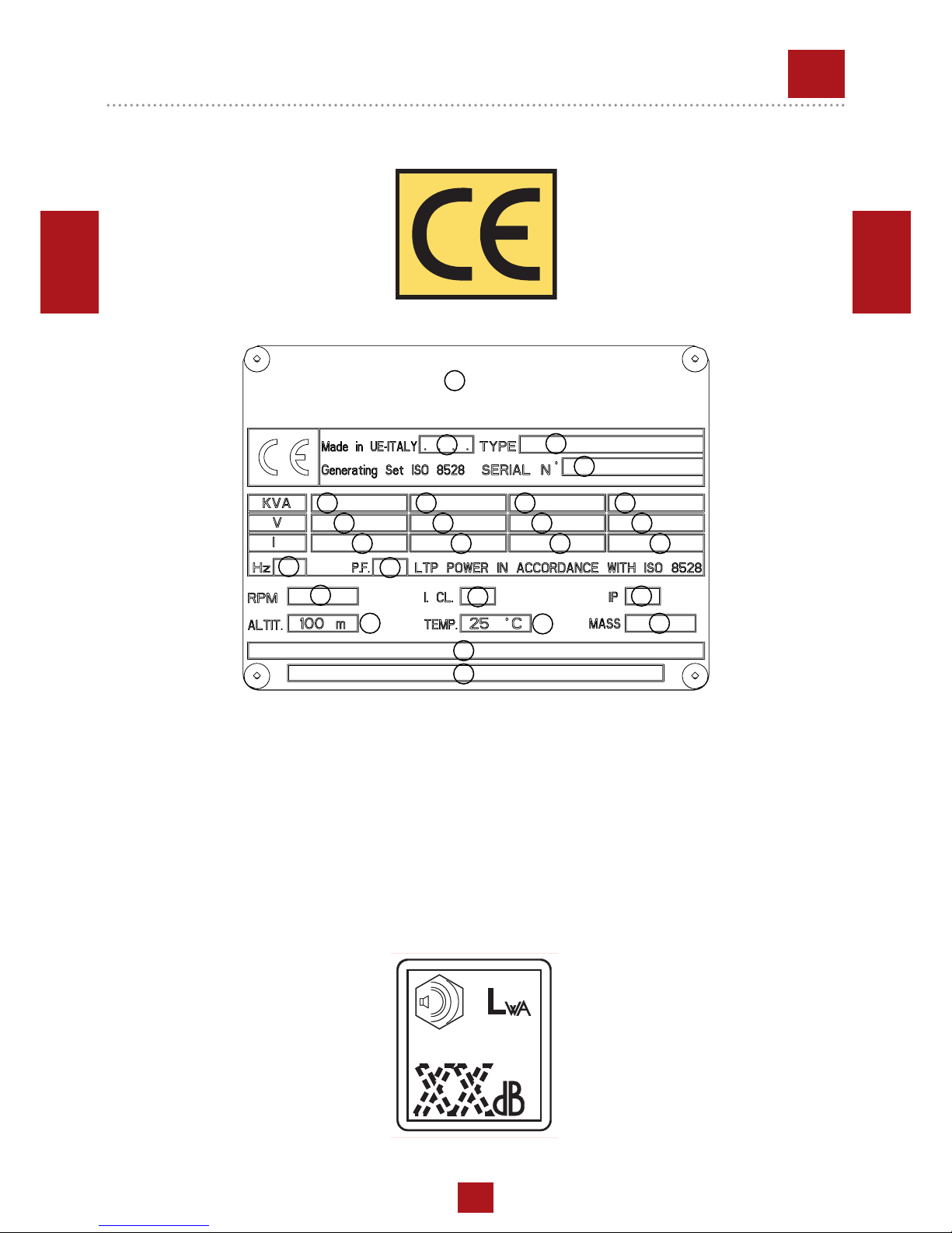
1. Name or brand supplier
2. Year of production
3. Generating Set model
4. Serial number | registration number
5. Power (kVA/kW)
6. Rated voltage (V)
7. Rated current (A)
8. Power (kVA/kW)
9. Rated voltage (V)
10. Rated current (A)
11. Power (kVA/kW)
12. Rated voltage (V)
13. Rated current (A)
14. Power (kVA/kW)
15. Rated voltage (V)
16. Rated current (A)
17. Rated frequency
18. Power factor cosφ
19. Engine rated speed
20. Insulation class
21. IP degree protection
22. Rated altitude (above sea level)
23. Max ambient temperature
24. Dry weight (kg)
25. Any additional information
Any of our product is labelled with CE marking attesting its conformity to appliable directives and also the fulllment of safety
requirements of the product itself; the list of these directives is part of the declaration of conformity included in any machine
standard equipment.
Here below the adopted symbol:
CE marking is clearly readable and unerasable and it can be either part of the data-plate.
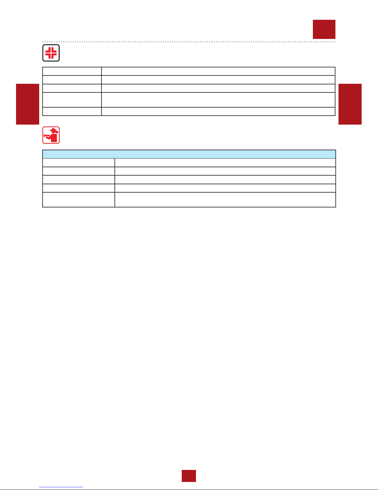
Furthermore, on each model it is shown the noise level value; the symbol used is the following:
The indication is shown in a clear, readable and indeleble way on a sticker.
REV.7-02/14
M
1.4
CE MARKING
GENERATING SETS
5
Page 6
13/11/14 M2_EN
ENGLISH
ENGLISH
REV.2-06/10
M
2
SYMBOLS AND SAFETY PRECAUTIONS
SYMBOLS IN THIS MANUAL
- The symbols used in this manual are designed to call your
attention to important aspects of the operation of the machine
as well as potential hazards and dangers for persons and
things.
Moreover, this symbolism intends to draw your attention
with the aim to give you indications for a correct use and,
as a result, to obtain a good operation of the machine or
equipment used.
SAFETY PRECAUTIONS
WARNING
This heading warns of situations which could result in injury
for persons or damage to things.
DANGEROUS
This heading warns of an immediate danger for persons as
well for things. Not following the advice can result in serious
injury or death.
CAUTION
To this advice can appear a danger for persons as well as
for things, for which can appear situations bringing material
damage to things.
IMPORTANT
NOTE
ATTENTION
These headings refer to information which will assis you in
the correct use of the machine and/or accessories.
!
!
!
!
!
!
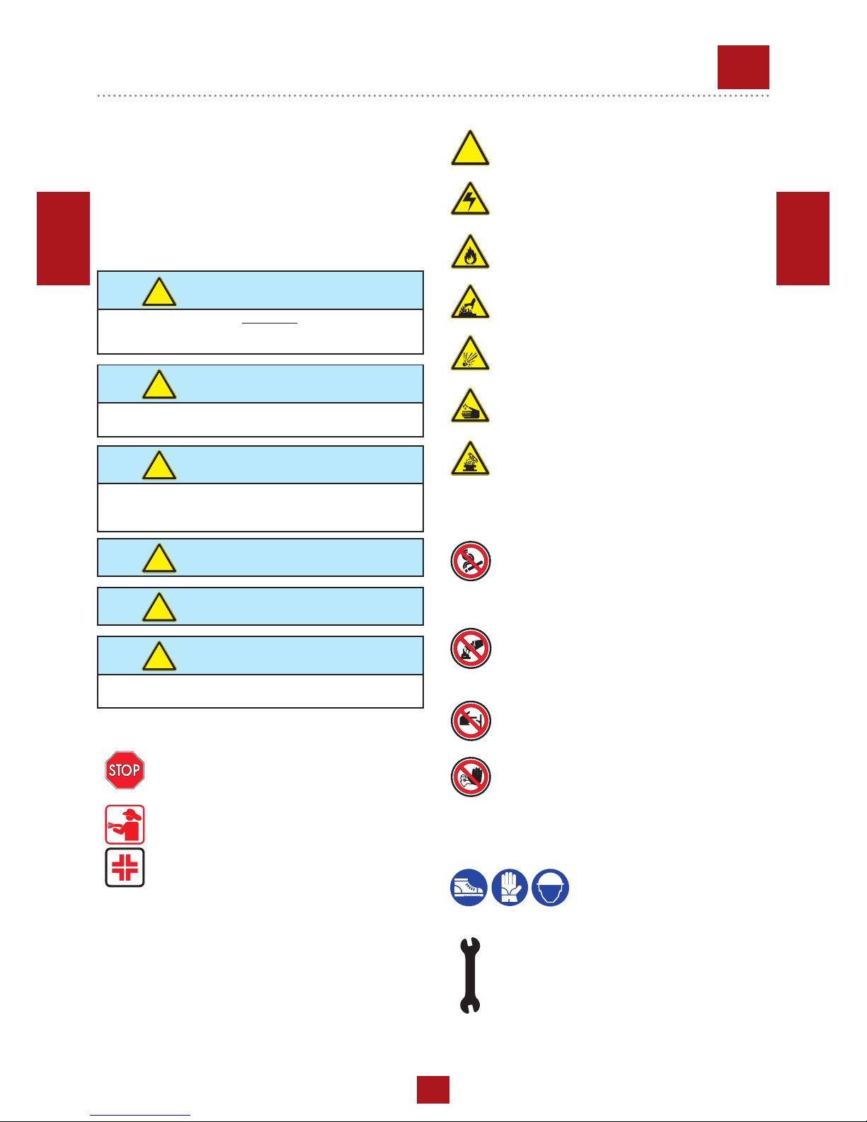
SIMBOLS
STOP - Read absolutely and be duly attentive
Read and pay due attention
DANGER
!
GENERAL ADVICE - If the advice is not respected damage can happen to persons or things.
HIGH VOLTAGE - Attention High Voltage.There
can be parts in voltage, dangerous to touch. The
non observance of the advice implies life danger.
FIRE - Danger of ame or re. If the advice is not
respected res can happen.
HEAT - Hot surfaces. If the advice is not respected
burns or damage to things can be caused.
EXPLOSION - Explosive material or danger of
explosion. in general. If the advice is not respected
there can be explosions.
ACIDS - Danger of corrosion. If the advice is not
respected the acids can cause corrosions with
damage to persons or things.
PRESSION - Danger of burns caused by the
expulsion of hot liquids under pressure.
PROHIBITIONS
It is prohibited to smoke while lling the tank with fuel.
The cigarette can cause re or explosion. If the
advice is not respected res or explosions can
be caused.
It is prohibited to use water to quench res on the electric
machine
If the advice is not respected res or damage to
persons can be caused.
Use only with non inserted voltage -
It is prohibited to make interventions before having
disinserted the voltage.
ACCES FORBIDDEN to non authorized peaple.
ADVICE
Use only with safety clothing -
It is compulsory to use the personal
protection means given in equipment.
WRENCH - Use of the tools. If the advice is not
respected damage can be caused to things and
even to persons.
6
Page 7
13/11/14 M2_EN
ENGLISH
ENGLISH
+ FIRST AID. In case the operator shold be sprayed by accident, from corrosive liquids a/o hot toxic gas or whate-
ver event which may cause serious injuries or death, predispose the rst aid in accordance with the ruling labour
accident standards or of local instructions.
+ FIRE PREVENTION. In case the working zone,for whatsoever cause goes on re with ames liable to cause severe
wounds or death, follow the rst aid as described by the ruling norms or local ones.
Skin contact Wash with water and soap
Eyes contact Irrigate with plenty of water, if the irritation persists contact a specialist
Ingestion Do not induce vomit as to avoid the intake of vomit into the lungs, send for a doctor
Suction of liquids from
lungs
If you suppose that vomit has entered the lungs (as in case of spontaneous vomit) take the subject to the hospital with the
utmost urgency
Inhalation In case of exposure to high concentration of vapours take immediately to a non polluted zone the person involved
EXTINCTION MEANS
Appropriated Carbonate anhydride (or carbon dioxyde) powder, foam, nebulized water
Not to be used Avoid the use of water jets
Other indications Cover eventual shedding not on re with foam or sand, use water jets to cool off the surfaces close to the re
Particular protection Wear an autorespiratory mask when heavy smoke is present
Useful warnings Avoid, by appropriate means to have oil sprays over metallic hot surfaces or over electric contacts (switches,plugs,etc.).
In case of oil sprinkling from pressure circuits, keep in mind that the inamability point is very low.
REV.2-06/10
M
2.1
WARNINGS
7
Page 8

13/11/14 M2.5 (GE-TF)_EN
ENGLISH
ENGLISH
GENERAL SAFETY INSTRUCTIONS
+ NOTE: the information contained in this manual are
subject to change without notice.
The instructions in this manual are intended as indicative only.
It is the responsibility of the owner/operator to evaluate risks
and potential damages in relation to the use of the product in
the specic conditions of application. Remember that the non
observance of the indications of this manual may result in damage to people or things.
In all cases, however, it is understood that the use shall be in
compliance with the applicable laws/regulations.
• Before operating the machine, read carefully the safety in-
structions contained in this manual and other manuals supplied (engine, alternator, etc.).
• All operations, handling, installation, use, maintenance, re-
pair should be carried out by authorized and qualied personnel.
• When operating, wear personal protective equipment (PPE):
footwear, gloves, helmet, etc..
• The owner is responsible for maintaining the equipment in
safe conditions.
Use only in perfect technical conditions
The machinery or equipment must be used in perfect tech-
nical condition. Remove immediately any defects that may
affect the safe conditions of use.
• Before starting to use this equipment it is important to take
knowledge of all the controls of the machine, all its functions
and its correct installation in order to avoid accidents to people and damage to the machine itself. In particular, it is
important to know how to stop the equipment quickly in case
of emergency.
• Do not allow the use of the machine to people unless pre-
viously instructed with all the information for a proper, safe
use.
• Forbid the access in the operational area to non authorized
personnel, children and pets so as to protect them from possible injury caused by any part of the machine.
SAFETY PRECAUTIONS DURING HANDLING AND TRANSPORTATION
• Lift the machine using only the points allocated for this fun-
ction.
The lifting eye (or eyes) and the correct positioning of the
forks of the forklift are marked with specic adhesives.
• Clear the operational area of possible obstacles and all un-
necessary personnel.
• Always use lifting equipment properly sized and controlled
by enabled bodies.
• It is forbidden to set on the frame of the equipment objects
or accessories that alter weight and center of gravity and
cause stresses not foreseen to the lifting points.
• Do not submit the machine and the lifting equipment to
swinging or shock which may transmit dynamic stress to the
structure.
Equipments with trailers or site tows
• Never drag the machine without trailer (or site tow)
• Check for a correct assembly of the machine to the towing
device.
• Always make sure that the hook of the vehicle is suitable for
towing of the total mass of the trailer.
• Do not tow the trailer if the coupling devices are worn or
damaged.
• Check for proper tire pressure.
• Do not replace the tires with types different from the original
ones.
• Check that the brakes and the optical signaling of the trailer
are working properly.
• Verify that the bolts of the wheels are in place and well
tightened.
• Do not park the machine (on trailer or site tow) on a steep
slope.
For the stops, not followed by a work session, always enga-
ge the parking brake and / or block the wheels by means of
wheel chocks.
• Do not tow the trailer on bumpy roads.
• Do not exceed the maximum permissible speed on public
roads of 80 km/h with the trailer, in any case comply with the
legislation applicable in the country of use.
• Do not use the site tow on public roads, this is intended for
use only in private and delimited areas. The maximum permitted speed is 40 km/h on smooth surfaces (asphalt or concrete), adapt in each case the speed to the type of ground.
SAFETY PRECAUTIONS DURING INSTALLATION AND
USE
• Always locate the machine on a at and solid ground, so as
to avoid tipping, slipping or falling during operation. Avoid
using the machine on slopes greater than 10 degrees.
• Make sure the area immediately surrounding the machine is
clean and free from debris.
• Connect the machine to an earthing system according to
the regulations in force at the place of installation. Use the
ground terminal on the front of the machine.
• Do not use the machine with wet or damp hands and / or
clothing.
• Use plugs suitable for the output sockets of the machine and
make sure that electrical cords are in good condition.
• The machine must always be positioned so that the exhaust
gases are dispersed in the air without being inhaled by people or living beings.
• If you use the machine indoors is necessary that the installation is designed and built by skilled technicians in a workmanlike manner.
• During normal operation, keep doors closed. The access to
the internal parts should be allowed only for maintenance
reasons.
• Do not place objects or obstructions in the vicinity of the air
intakes and air outlets, a possible overheating of the gene-
rator could cause a re.
• Keep area near to the mufer free from objects such as
rags, paper, cardboard. The high temperature of the mufer
could cause the burning of objects and cause re.
• Immediately stop the machine in case of malfunction.
Do not restart the machine without rst having found and
xed the problem.
REV.0-03/15
M
2.5
SAFETY RULES
GENERATING SETS - LIGHTING TOWERS
8
Page 9
13/11/14 M2.5 (GE-TF)_EN
ENGLISH
ENGLISH
SAFETY PRECAUTIONS DURING MAINTENANCE
• Make use of qualied personnel to carry out maintenance
and troubleshooting.
• It is mandatory to stop the engine before performing any
maintenance on the machine.
• Always use protective devices and suitable equipment.
• Do not touch the engine, the exhaust pipes and the mufer
during operation or immediately after. Allow the engine to
cool before performing any operation.
• With the machine running pay attention to moving parts
such as fans, belts, pulleys.
• Do not remove the protections and the safety devices unless
absolutely necessary, restore them after completion of the
maintenance or repair.
• Do not refuel while the engine is running or hot. Do not smo-
ke or use naked ames when refueling.
• Refuel only outdoors or in well ventilated areas.
• Avoid spilling fuel, especially on the engine. Clean and dry
any leaks before restarting the machine.
• Slowly unscrew the cap of the fuel tank and put it back
always after refueling.
• Do not ll the tank completely to allow for expansion of the
fuel inside.
• Do not remove the radiator cap when the engine is running
or still hot, the coolant may spurt out and cause serious
burns.
• Do not handle the battery without the use of protective gloves, the battery uid contains sulfuric acid, which is very corrosive and dangerous.
• Do not smoke, avoid any naked ames or sparks near the
battery, the vapors exhaled could cause the battery to explode
REV.0-03/15
M
2.5.1
SAFETY RULES
GENERATING SETS - LIGHTING TOWERS
SAFETY PRECAUTIONS DURING HANDLING AND TRANSPORTATION
• Before moving a lighting tower lower the telescopic mast
and block properly all movable parts such as the access do-
ors, the mast, the outriggers, the oodlights.
• Check the fastening of the wheels of the trolley.
SAFETY PRECAUTIONS DURING INSTALLATION AND
USE
• Make sure the area above the lighting tower is free from
overhead cables or other obstacles.
• Before raising the mast extract the outriggers located at
the sides of the machine. Acting on the outriggers level the
lighting tower making use of the bubble, so as to bring the
equipment in a horizontal position. Make sure that the tower rests securely on the outriggers. If the lighting tower is
mounted on road trailer pull the handbrake.
• Do not operate the lighting tower if the wind speed exceeds
the safe speed indicated or if it is expected the arrival of
storms or thunderstorms in the area.
• Lower the telescopic mast when the tower is not used.
• Always check the good condition of the power cable before
connecting the lighting tower to the generating set.
• Do not touch and do not place objects on the lamps during
operation or immediately after use. The lamps become very
hot.
• Do not turn on the lamps without the protective glass or with
the same broken or damaged.
• Make sure all the ropes and the manual winch are in perfect
condition.
• Place the lighting tower in order to avoid that the winch can
receive shocks which may cause damage to the automatic
brake.
SAFETY PRECAUTIONS DURING MAINTENANCE
• Turn off the generating set or unplug the power cable before
carrying out any type of maintenance on the lighting tower.
• Always cut off power to the lamps and wait for their cooling
before performing any maintenance or replacement.
• Before carrying out any type of maintenance or repairs on
the generating set refer to the manual of the generating set
and the other manuals supplied.
ATTENTION
The lighting towers is designed to be used with a generating
set or with a xed mass on its base. The weight and positioning of the generating set on the base are essential for the
safety of the lighting tower.
Failure to comply with this provision causes a serious danger
of tipping or instability during operation and during handling
with site tow If necessary, contact the service.
!
ADDITIONAL PRECAUTIONS FOR LIGHTING TOWERS
9
Page 10
02/05/18 CF1CB051_EN
ENGLISH
ENGLISH
M
0
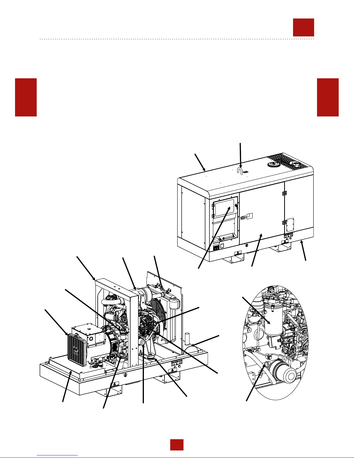
DESCRIPTION OF THE MACHINE
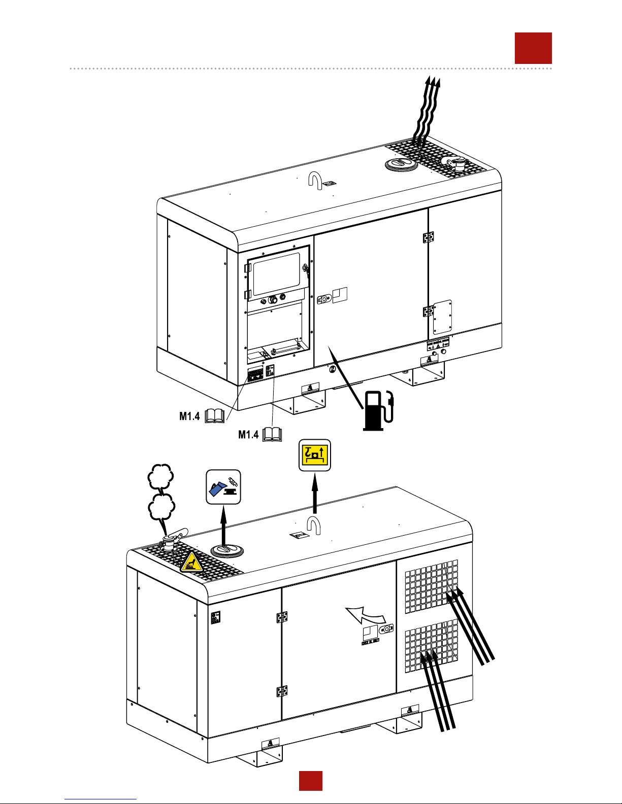
REV.0-05/18
VIBRATION
DAMPER
ROLL-BAR
ENGINE OIL
RESERVOIR CAP
The generating set is a unit which transforms the mechanical energy, generated by endothermic engine, into electric
energy, through an alternator.
The models FSX are a super silenced generating sets. The machine construction incorporates an integral roll bar, one central
lifting point, forklift pockets and rear canopy section that is hinged to provide full access to the engine for maintenance.
This attention to detail can also be seen in the rounded edges of the canopy designed for rainwater drainage away from the
control panel. The bunded base must ensure the containment of uids in the engine and fuel tank in the event of any loss, to
prevent their dispersion in the environment.
The recessed control panel houses the sockets and machine.
BASE
MUFFLER
OIL LEVEL
DIPSTICK
WATER
FILLING CAP
FUEL
TANK CAP
AIR FILTER
TANK
CENTRAL LIFTING
POINT
ALTERNATOR
FRONT
PANEL
CANOPY
ENGINE
ACCESS
DOOR
FUEL FILTER
FUEL PREFILTER
OIL FILTER
10
Page 11

0.1
RECORDING DATA
REV.1-11/14
The manual is for the range of machines indicated on the front cover.
With the scope to facilitate the search of the spare parts and maintain information of the bought machine, is necessary to record
some data.
Please write the requested data inside the squares to side:
1. Model of machine
2. Serial number of the machine
3. Serial number of the engine
4. Name of the dealer where bought the machine
5. Address of the dealer
6. Phone number of the dealer
7. Date of the bought machine
8. Notes
RECORDING DATA
1.
2.
3.
4.
5.
6.
7.
8.
16/10/15 Registrazione Dati_EN
ENGLISH
ENGLISH
11
Page 12
30/03/00 M3_EN
ENGLISH
ENGLISH
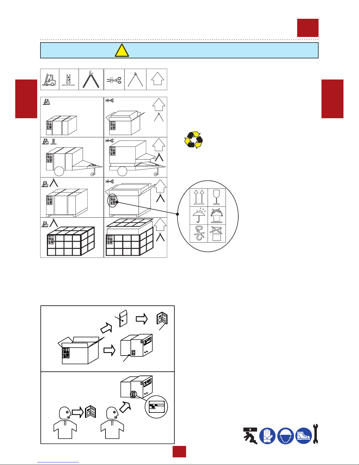
NOTE
!
+ Be sure that the lifting devices are: correctly mounted,
adequate for the weight of the machine with it’s packaging,
and conforms to local rules and regulations.
When receiving the goods make sure that the product has
not suffered damage during the transport, that there has
not been rough handling or taking away of parts contained
inside the packing or in the set.
In case you nd damages, rough handling or absence of
parts (envelopes, manuals, etc.), we advise you to inform
immediately our Technical Service.
For eliminating the packing materials, the User must
keep to the norms in force in his country.
1) Take the machine (C) out of the shipment packing. Take out
of the envelope (A) the user’s manual (B).
2) Read: the user’s manual (B), the plates xed on the machine,
the data plate.
2
B
A
1
C
REV.1-02/04
M
3
MACHINE UNPACKING
12
Page 13
02/06/10 M4-2_cof_EN
ENGLISH
ENGLISH
GENERAL PRECAUTIONS WHEN HANDLING THE MACHINE.
To limit the dangers involved in moving a generating set, it is
important to carefully follow the guideline set out below:
• Transportation must always take place with the engine off
and electrical cables and starting battery disconnected and
fuel tank empty.
• Particular attention must be paid to SKID version generating sets (without canopy) that have very delicate parts
unprotected from bumps (injection pump, speed regulator,
radiator, electrical panel connections and instrumentation).
• Generating sets must be protected from bad weather during transport: the units must be entirely covered, especially
the electrical parts (alternator and control panel).
• Some engine parts retain heat even after it has been shut
off: therefore it is necessary to wait for the engine to cool
before covering it to avoid the risk of re.
• Clear the moving zone of all possible obstacles and from all
unnecessary personnel.
• Use properly sized lifting equipment regularly submitted to
major overhaul by an authorized organisation. It is prohibited to fasten objects or accessories on the generating set
baseframe that may modify weight and center of gravity
and may cause movements unforeseen by the lifting eyes.
• Do not subject the generating set and lifting equipment to
abrupt or undulating movements that pass on stress dynamics to the structure.
• Do not lift the generating set higher than what is absolutely
necessary.
• Transportation of separate manual or automatic control
panels must be carried out very carefully in order to avoid
damage to the equipment contained inside the panel and to
the instruments on the front.
• To access the hook points on the top of the unit, use approved ladders only or support from another operator: climb
the ladder using non-skid shoes.
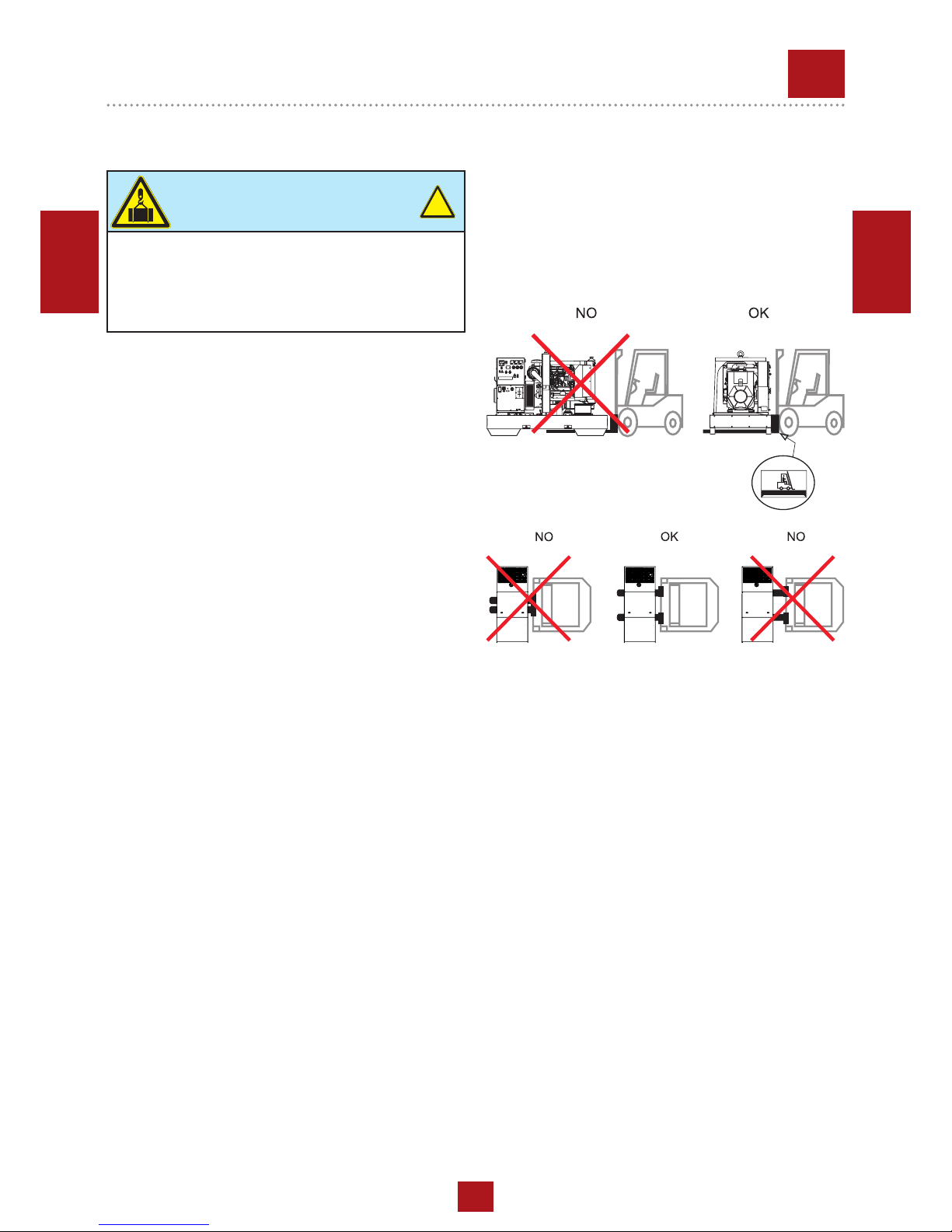
ATTENTION
When moving/lifting a genset it is imperative to be extremely careful. All moving operations must be carried
out be qualied persons.
Due to the weight and encumbrance of the genset, an
error while moving/lifting the unit may cause serious
damage to it or surrounding persons.
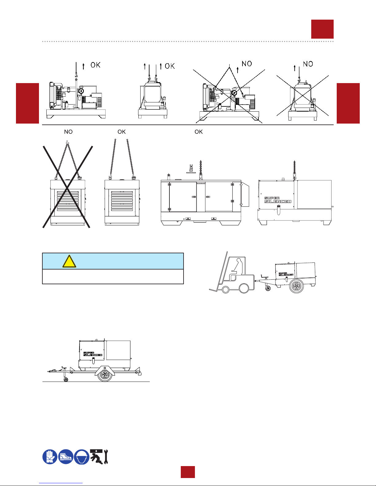
MOVING METHOD
The generating sets are lifted with different methods according
to the unit’s conguration. Below are the main methods of moving/lifting the genset.
MOVING THE GENERATING SET VIA FORKLIFT
When lifting with a forklift it is necessary to fork the baseframe
sideways so that the forks stick out from one side to the other
side, widening them to distribute the weight properly, maintaining the genset level.
Stickers on the base indicate where to place the lifter forks.
!
MOVING THE GENERATING SET VIA CABLES OR CHAINS
When lifting the genset with the aid of cables or chains it is necessary to use equipment periodically checked by a licensed
organisation. Hook the cables only on to the points provided
for this use and shown via the appropriate stickers.
For correctly moving the generating set:
• DO NOT lift the genset by fastening cables to the lifting
eyes on the engine or alternator (these are only used for
lifting the single components).
• DO NOT make abrupt or undulating movements that pass
on stress dynamics to the structure.
• DO NOT leave the generating set suspended for longer
than absolutely necessary to move the unit.
• Use all the lifting eyes provided.
• Use cables and/or chains of equal length so that the weight
is distributed evenly.
REV.0-06/10
M
4.2
TRANSPORT AND HANDLING
13
Page 14
02/06/10 M4-2_cof_EN
ENGLISH
ENGLISH
MOVING BY SITE TROLLEY / TRAILER
Trolleys/trailers should only be used to move the generating
set for which they were designed.
ROAD TROLLEY CTV:
BEWARE
DO NOT TOW the generating set without trailer, be it
manually or using a vehicle.
!
made by using a general use standard trailer on which the
genset is xed: it is type approved for transport on public roads
by licensed organisations. The maximum speed allowed is 80
km/h however, the transportation laws in force in the place of
MOVING THE GENERATING SET VIA CABLES OR CHAINS
use should be respected.
SITE TOW CTL:
this trailer is made by the manufacturer and connected to the
generating set baseframe, it can not be towed on public roads.
Therefore it can only be used on private roads and no through
trafc zones.
The maximum speed allowed is 40 km/h on smooth surfaces
(asphalt, cement) and, in any case, the laws in force in the
place of use should be respected.
Always follow the directions below for any tipe of tow:
• DO NOT park the generating set/trolley assy, on slant
ground
• When parking always use the emergency/hand brake and/
or safety clamps.
• DO NOT tow the trailer on bumpy roads.
MOVING THE UNIT VIA MOTOR VEHICLE
During transportation with a motor vehicle, it is important to
use appropriate belts/straps to stabilise the unit, therefore
avoiding that unexpected bumps or jolts can cause damage
to the baseframe, engine, or worse, overturn the load. It is the
carrier’s responsibility to always respect the highway code in
force.
OK
REV.0-06/10
M
4.2.1
TRANSPORT AND HANDLING
14
Page 15
02/05/18 CF1CB051_IT
M
2.7
INSTALLAZIONE - INSTALLATION - INSTALLATION
INSTALACIÓN - LUFTZIRKULATION - INSTALAÇÃO
УСТАНОВКА - INSTALLATIE
REV.0-05/18
15
Page 16

02/06/10 M2-6_(raff_acqua)_EN
ENGLISH
ENGLISH
GENERAL INSTALLATION CRITERIA
Installation of a genset has to be planned by qualied and
trained technicians, it has to be carried out by a competent
organization with qualied personnel and proper equipment.
Before proceeding with installation the following conditions
have to be checked:
• Genset has been selected according to needs of
the electrical load and to environmental conditions
(temperature, altitude and humidity);
• Genset location is of appropriate dimensions and allows
accessibility to genset for maintenance and/or necessary
repairs;
• If genset is indoors, ensure there is enough air for engine
combustion, for genset cooling (radiator and generator),
and sufcient ventilation;
• If genset is indoors, a system of expulsion for engine
exhaust gas is provided;
• Personnel safety has been carefully considered;
• Noise-level issues have been carefully considered;
• Fuel and lubricant stocking issues have been considered in
accordance to norms in force in the country of installation.
ATTENTION
Faulty installation can create damage to the genset and the
User system, and injury to persons.
It is compulsory to install the genset according to the norms
in force in the country of installation.
The installing company must provide a conformity declaration stating that installation has been carried out duly and
according to plans and to norms in force.
ATTENTION
All generating sets are equipped with a control system that
is NOT inuenced by standard environmental factors and
is able to stop the unit in case of anomalous values in the
fundamental parameters.
In order to avoid unexpected black-outs or other potentially
dangerous situations, the below installation indications must
be followed.
INFORMATION
Italian and European norms dene specic characteristics
referring to the premises in which genset should be located,
indicating possible positioning, minimum dimensions, etc.
For any doubt referring to installation location contact our
technical sales ofce.
!
!
ENVIRONMENTAL CONDITIONS
ATTENTION
Open gensets (SKID) have to be located in an area protected from rain, snow, high humidity and direct exposure to
the sun.
Rain or high humidity on GE genset alternator, in particular during operation, cause an increase in voltage output,
winding faults, electric discharge towards ground, with damage to the genset and injury to persons. Dust, in particular
saline dust, must be avoided. In case radiator or air lters
are obstructed, there is the risk that genset will overheat
or be damaged. Aspiration grills must not be obstructed by
leaves, snow, etc.
!
OUTPUT OF FUMES IN OPEN AIR CONDITIONS
DANGER
Genset must be positioned so that exhaust gas is diffused
without being inhaled by any living being.
Engine exhaust gas contains carbon monoxide, which is
harmful to one’s health, and in big quantities can cause intoxication and death.
Local norms in force have to be respected.
!
OUTDOOR INSTALLATION
REV.0-06/10
M
2.6
INSTALLATION INSTRUCTIONS
16
Page 17

02/06/10 M2-6_(raff_acqua)_EN
ENGLISH
ENGLISH
SAFE DISTANCE
FIXING
In order to absorb vibrations produced by genset, it should
be xed to a surface with sufcient rigidity, isolated against
vibrations towards other structures and with a mass equal to
at least three times the genset mass.
DO NOT locate the genset on terraces or raised levels, if its
characteristics have not been previously veried as suitable.
ATTENTION
A safe distance has to be kept between genset and fuel deposits, inammable goods (cloths, paper, etc.), chemicals,
according to indications provided by the authority in charge. In order to avoid potentially dangerous situations, area
surrounding genset should be isolated so that unauthorized
people will not be able to get close to the unit. Even if MOSA
gensets are manufactured according to electromagnetic
compatibility norms, we suggest NOT to install the genset
near machinery that can be inuenced by magnetic elds.
NOTE
When using a genset it is advisable to adopt precautions to avoid that fuel, lubricant and other engine liquids may accidentally cause soil pollution.
The most recent generators are designed to retain possible liquid leakages, hence no specic measures are
needed in this regard.
In case of doubts concerning your genset do not hesitate to contact our technical sales ofce.
!
!
ATTENTION
Engine and alternator when in operation produce heat:
• Shelter should NOT obstruct normal cooling of components;
• Exhaust gas should be directed in order to avoid the possibility that alternator and engine fan inhale it;
• Shelter should be made of reproof material, as embers
may come out of the exhaust pipe;
• Never cover or wrap up genset with plastic sheets or other
material while operating. If genset is off, make sure engine has cooled before you cover it, or else there may be
risk of damage to the genset or may catch re.
!
TEMPORARY OUTDOOR INSTALLATION
Indications given for xed installation have to be followed.
If genset is not positioned correctly, vibrations transmitted to
the baseframe may cause the genset to move, this may occur
while the genset has a load inserted, take on all necessary
precautions to avoid this.
LA=LARG. G.E.
LA=WIDTH G.S.
LA=LARGEUR G.E.
LA=LARGO G.E.
Sample of outdoor installation with shelter
FIXED OUTDOOR INSTALLATION
If a shelter is used to protect the genset (see gure), it should
NOT be attached to it.
Even if a shelter is temporary the below indications should be
followed:
REV.0-06/10
M
2.6.1
INSTALLATION INSTRUCTIONS
17
Page 18

02/06/10 M2-6_(raff_acqua)_EN
ENGLISH
ENGLISH
H=ALTEZZA G.E.
H=HEIGTH G.S.
H=HAUTEUR G.E.
H=ALTEZA G.E.
INDOOR INSTALLATION
In order to avoid endangering or damaging genset following
indications must be followed.
Genset installation location has to be in accordance to the
norms in force.
ref. Description
1 Generating set
2 Auxiliary aspirator
5 Exhaust pipe
7 Exhaust pipe protection and insulation
8 Raincover and anti-intrusion grid
9 Exhaust conduit
11 Location area with isolated foundation
12 Air inlet with anti-intrusion grid
13 Entrance door
14 Containment step
Minimum suggested dimension table
A Length G.E. + 1000 mm
B Width G.E. + 2000 mm
C Width G.E. + 200 mm
D Length G.E. + 400 mm
E Width G.E. + 400 mm
H Height G.E. + 1500 mm (>2500 mm)
Note: dimensions required by norms in force have to be respected in any case.
SURFACE AREA
The best solution is to create a base isolated from the rest of
the structure, on which the genset will be located, in order to
avoid vibrations being transmitted.
The base must be built with reinforced concrete and there
must be the possibility to x the genset to it by using screw
anchors or rag bolts.
Base dimensions should exceed genset dimensions of at least
200 mm on each side. Base should weigh three times static
genset weight (indicated on the technical date).
Floor should be levelled and suitable to sustain genset weight.
Thresholds on doors and openings should have a barrier in order to avoid liquids leaking. In case it is not possible to provide
a door with a barrier, the genset should have a collection base
appropriate for the quantity of liquid it contains, in any case
dimensions of collection base must be in accordance to the
laws in force in country of installation.
ROOM OPENINGS AND VENTILATION
The room should have a ventilation system sufcient enough
to avoid stagnation and circulation of overheated air.
Openings for incoming and outgoing air should be of appropriate size, considering minimum required air ow and maximum back pressure, values that can be checked on the engine
manual.
Opening for the air entrance should be near the back part of
the genset as close as possible to the ground.
If openings for air ow are not aligned with genset it may be
necessary to add air conduits to avoid any air dispersion (see
gure).
Sample of outdoor installation with shelter
REV.0-06/10
M
2.6.2
INSTALLATION INSTRUCTIONS
18
Page 19

02/06/10 M2-6_(raff_acqua)_EN
ENGLISH
ENGLISH
For open gensets installed indoors, we recommend:
• The dimensions of the air outlets be such that they have
at least the same area of the radiator;
• the dimensions of the windows for air outlet is at least on
the surface of the radiator.
• The dimensions of the air inlets be such that they have at
least the same area of the radiator +10% for gensets up to
130 kVA or +25% for gensets beyond 130 kVA;
For canopied gensets installed indoors, we recommend:
• The dimensions of the air outlets be such that they have
at least the same area of the generator air outlets, as indicated at page M2.7 of the present manual;
• The dimensions of the air inlets be such that they have at
least the same area of the generator air inlets, as indicated at page M2.7 of the present manual +10% for gensets
up to 130 kVA or +25% for gensets beyond 130 kVA;
The opening area has to be calculated considering protection
grill surface, in order to insure that remaining free area is sufcient.
Dimensions of openings calculated as above indicated, are
the minimum acceptable dimensions in case of L.T.P. use; the
pressure remaining after radiator and back pressure must be
considered while planning dimensions of the piping.
To calculate the opening section check below drawing:
WARNING: to avoid reux of heated air and loss of load, add
an air duct between radiator and opening.
To consider the correct quantity of heat to be discharged, loss
of heat on duct should be evaluated. If the duct is not appropriately insulated, room-temperature may increase considerably, for this reason it may be necessary to install an electro
ventilator for correct air exchange.
a Radiator surface
b Free opening
c
Air ow opening with grill and 80% of open
surface
d Air ow opening with bafe plates
Electro ventilator capacity can be calculated as follows:
ATTENTION
Exhaust piping may reach up to 600 °C during operation, therefore it is compulsory to cover piping with appropriate insulation.
!
Fan Capacity [m3/h]=
Transmitted heat [Kcal/h]
0,287
x ∆t [°C]
Considering:
• heat to radiation is indicated on engine/alternator technical
data sheet;
• 0. 287 is specic heat for each m3 of air at 20°C;
• Δt in °C is usually considered as equal to 5 °C (worst
conditions are considered).
EXHAUST PIPING
Exhaust piping must be built in accordance to laws in force in
the country of installation.
General indications:
• Minimum required thickness: 2.0 mm;
• Diameter of piping has to be calculated considering, length,
number of bends, type of exhaust mufer, and any other
accessory used on it. Back pressure should not exceed
values provided by manufacturer, as this causes loss
of power and damage to the engine.
DANGER
Engine exhaust gas contains carbon monoxide, harmful to health and in large quantities can cause intoxication or death.
• Exhaust piping should be composed of parts, connected
by anges with gaskets, for easy disassembling and grant
maximum tightness.
• Exhaust piping should be connected to engine by a ex that
should absorb dilatation and separate x part from engine
piping.
• Exhaust piping should not weigh on engine manifold.
!
REV.0-06/10
M
2.6.3
INSTALLATION INSTRUCTIONS
19
Page 20

12/06/03 M20 (raff_acqua)_EN
ENGLISH
ENGLISH
LUBRICANT
RECOMMENDED OIL
The manufacturer recommends selecting AGIP engine oil.
Refer to the label on the motor for the recommended products.
Please refer to the motor operating manual for the recommended
viscosity.
REFUELLING AND CONTROL:
Carry out refuelling and controls with motor at level position.
1. Remove the oil-ll tap (24)
2. Pour oil and replace the tap
3. Check the oil level using the dipstick (23); the oil level must
be comprised between the minimum and maximum indicators.
AIR FILTER
Check that the dry air lter is correctly installed and
that there are no leaks around the lter which could lead to
inltrations of non-ltered air to the inside of the motor.
BATTERY WITHOUT MAINTENANCE
The starter battery is supplied already
charged and ready for use.
Before starting the gen-set connect
the cable + (positive) to the pole + of
the battery, by properly tightening the
clamp. In case of models with warning
light: check the state of the battery by
means of the indicator placed in the upper part.
- Green colour: battery OK
- Black colour: battery to be recharged
- White colour: battery to be replaced
DO NOT OPEN THE BATTERY.
FUEL
Rell the tank with good quality diesel fuel, such as automobile
type diesel fuel, for example.
For further details on the type of diesel fuel to use, see the motor
operating manual supplied.
Do not ll the tank completely; leave a space of approx. 10
mm between the fuel level and the wall of the tank to allow for
expansion.
In rigid environmental temperature conditions, use special
winterized diesel fuels or specic additives in order to avoid
the formation of parafn.
ATTENTION
Stop engine when fueling. Do not smoke or use
open ames during refuelling operations, in order
to avoid explosions or re hazards.
Fuel fumes are highly toxic; carry out operations
outdoors only, or in a well-ventilated environment.
Avoid accidentally spilling fuel. Clean any eventual leaks before starting up motor.
!
ATTENTION
It is dangerous to ll the motor with too much oil, as its combustion can provoke a sudden increase in rotation speed.
!
REV.2-04/15
M
20
SET-UP FOR OPERATION
(DIESEL ENGINE)
WATER COOLED SYSTEMS
20
Page 21

12/06/03 M20 (raff_acqua)_EN
ENGLISH
ENGLISH
COOLING LIQUID
Remove the tap and pour the liquid coolant into the radiator;
the quantity and composition of the liquid coolant are indicated
in the motor operating manual. Replace the tap, ensuring it is
perfectly closed.
After relling operations, allow the motor to run for a brief time
and check the level, as it may have diminished due to air bubbles present in the cooling circuit; restore the level with water.
To replace the liquid coolant, follow the operations described
in the motor operating manual.
ATTENTION:
The engine cooling system is originally lled with coolant type:
AGIP ANTIFREEZE EXTRA
During the engine life it is strongly recommended to use the
same coolant type. This is because a coolant change would
require a careful cleaning of the cooling system, which is not
an easy job. A lack in tacking these precautions would result in
the mix of different additives used in different coolants which
would originate gelatinous substances capable of obstructing
the cooling system.
ATTENTION
Do not remove the radiator tap with the motor in operation or
still hot, as the liquid coolant may spurt out and cause serious
burns. Remove the tap very carefully.
ATTENTION
A qualied electrician should carry out electrical connections according to the norms in force.
!
ELECTRICAL CONNECTIONS
The electrical connection to the User system is a very important operation: safety and good operation of the genset and
User system depend on a correct electrical connection.
Before supplying User system always check:
• that wires connecting gen-set to the user plant are suitable
to the supplied voltage and are in accordance to the applicable rules;
• wire type, section and length have been calculated considering environment conditions and in force norms;
• ground is functioning correctly: earth fault relay device works only if this connection is operating;
• that direction of the phases corresponds to the user plant
phase rotation, and none of the phases has been accidentally connected to neutral.
REV.2-04/15
M
20.1
SET-UP FOR OPERATION
(DIESEL ENGINE)
WATER COOLED SYSTEMS
21
Page 22

14/10/13 Messa a Terra_EN.indd
ENGLISH
ENGLISH
REV.0-10/16
EARTHING KIT
EARTHING KIT WITHOUT GROUND FAULT INTERRUPTER
The protection against electric shock from contact indirect is
ensured by the “electrical separation” with equipotential bonding
between all the exposed conductive parts of the generating set.
The generating set is NOT equipped with a earth leakage circuit
breaker because its windings are not connected to ground,
hence the machine should NOT be intentionally connected to
a grounding circuit.
The limitation of the extension of the electric circuit is very
important for safety, do not power supply to electric plants with
a length greater than 200 meters.
It is important that the power cords of the equipment are equipped with the protective conductor, yellow-green cable, in order
to ensure the connection between the exposed conductive parts
of the generating set and the equipment; this provision does not
apply to the class II equipment (double insulation or reinforced
insulation) recognizable by the symbol
.
The cables must be suitable environment in which it operates.
It should be noted that with temperatures below 5°C PVC cables
become stiff and PVC insulation tends to cut to the rst fold.
The protection by electrical separation is NOT suitable if the
machine is destined to supply power complex plants or located
in special environments with greater risk of electric shock.
In these cases it is necessary to adopt security measures
electricity provided by law.
For EXAMPLE, you can install a GFI (Ground Fault Interrupter
or Earth Leakage Circuit Breaker) high sensitivity 30mA, and
grounding the Neutral of the generating set: this operation
must be performed by a qualied electrician or at a authorized
service provider.
The grounding of the generating set is now mandatory to ensure
protection against indirect contact by means of the GFI.
Connect the generating set to an earthing system via a cable
certain efciency using the ground terminal (12) on the machine.
EARTHING KIT WITH GROUND FAULT INTERRUPTER
The grounding connection to an earthed installation is obligatory for all models equipped with a differential switch (circuit
breaker). In these groups the generator star point is generally
connected to the machine’s earthing; by employing the TN or TT
distribution system, the differential switch guarantees protection
against indirect contacts.
In the case of powering complex installations requiring or employing additional electrical protection devices, the coordination
between the protection devices must be veried.
For the grounding connection, use the terminal (12); comply
to local and/or current regulations in force for electrical installations and safety
EARTHING KIT WITH ISOMETER
Machines equipped with insulation resistance monitor allow
intentionally not to connect the ground terminal PE (12) to an
earthing system.
Located on the front of the machine the insulation resistance
monitor has the function of continuously monitoring the ground
insulation of live parts.
If the insulation resistance falls below the pre-set fault value,
the insulation resistance monitor will interrupt the supply of the
connected equipment.
It is important that the power cords of the devices are provided
with the green-yellow circuit protective conductor, so as to ensure the bonding among all the grounds of the equipment and
the ground of the machine; the latter provision does not apply
to equipment with double insulation or reinforced insulation.
NOTE: it is possible to connect the PE terminal (12) to an
own ground connection. In this case an IT earthing system is
accomplished, this means with the active parts isolated from
earth and the equipment cases grounded.
In this case, the insulation resistance monitor checks the insulation resistance of the active parts both towards case and ground,
for example, the insulation towards ground of the power cables.
22
Page 23

21/02/18 CN4F4051_EN
ENGLISH
ENGLISH
1) make sure the load plugs are di-
sconnected or that the main switch
of machine is open (lever facing
down), so as to ensure the motor’s
start-up without any loads inserted.
REV.0-02/18
M
21
STARTING AND STOPPING
NOTE
Do not alter the primary conditions of regulation and do
not touch the sealed parts.
!
Check daily
TEMPERATURE TIME
≤ - 20° C
5’
- 20° C / - 10° C 2’
- 10° C / - 5° C 1’
≥ - 5° C
20”
2) The engine starts up at its operating speed. After start-up,
allow the engine to run for a few minutes before powering
on the utilities. See table
3) Start-up at low temperatures.
The motor will normally start up without problems down to
temperatures of -10° C.
For start-up and use at lower temperatures please see the
engine manual or turn to our Technical Assistance Center.
STOP
For shutdown under normal conditions, proceed as follows:
1) stop the power source, turning off the connected equipment,
if they do not have a power switch, open the main switch of
the machine (lever facing down)
2) allow the engine to run without any load for a few minutes
3) press the controller’s STOP button.
Emergency shutdown
To stop the group in a dangerous situation, press the emergency
stop button (L5).
To reset the knob, turn it clockwise.
START
The engine is started and stopped by operating
directly on the InteliNANO PLUS or AMF 25
controller.
Consult the controller manual for a complete
understanding of its performance.
23
Page 24

21/02/18 CN4F4051_EN
ENGLISH
ENGLISH
1) make sure the load plugs are di-
sconnected or that the main switch
of machine is open (lever facing
down), so as to ensure the motor’s
start-up without any loads inserted.
REV.0-02/18
M
21
STARTING AND STOPPING
NOTE
Do not alter the primary conditions of regulation and do
not touch the sealed parts.
!
Check daily
TEMPERATURE TIME
≤ - 20° C
5’
- 20° C / - 10° C 2’
- 10° C / - 5° C 1’
≥ - 5° C
20”
2) The engine starts up at its operating speed. After start-up,
allow the engine to run for a few minutes before powering
on the utilities. See table
3) Start-up at low temperatures.
The motor will normally start up without problems down to
temperatures of -10° C.
For start-up and use at lower temperatures please see the
engine manual or turn to our Technical Assistance Center.
STOP
For shutdown under normal conditions, proceed as follows:
1) stop the power source, turning off the connected equipment,
if they do not have a power switch, open the main switch of
the machine (lever facing down)
2) allow the engine to run without any load for a few minutes
3) press the controller’s STOP button.
Emergency shutdown
To stop the group in a dangerous situation, press the emergency
stop button (L5).
To reset the knob, turn it clockwise.
START
The engine is started and stopped by operating
directly on the InteliNANO PLUS or AMF 25
controller.
Consult the controller manual for a complete
understanding of its performance.
24
Page 25

02/05/18 CF1CB051_EN
ENGLISH
ENGLISH
M
32
CONTROLS DESCRIPTION
REV.0-05/18
Pos. Description Function
Z2 Thermal-magnetic circuit
breaker
General switch for the gen-set.
It protects both gen-set and related electrical circuit from over current /short
circuit.
D Ground fault interrupter
(30 mA)
Device for protection against not-direct contacts for TN and TT systems
(neutral grounded to frame)
N2 Thermal-magnetic circuit
breaker/
Ground fault interrupter
1x32A Curve C 4P - Id=0.03 (for 32A socket)
1x16A Curve C 4P - Id=0.03 (for 16A socket)
2x16A Curve C 2P - Id=0.03 (for 16A-230V socket)
T5 (SR) Earth leakage relay Ground fault interrupt (GFI) relay - Protection device against indirect contact
for TN systems (GE neutral to ground).
It opens the general circuit breaker, thereby interrupting the power supply to
the electrical system.
The regulations on the GFI must be performed by qualied personnel.
A3 (SR) Insulation monitoring Residual current monitor (RCM) - Protection device against indirect contact
for IT systems (GE neutral not to ground).
It opens the general circuit breaker when the isolation resistance falls below
the selected threshold, thereby interrupting the power supply to the electrical system.
The regulations on the RCM must be performed by qualied personnel.
Q3 Output power terminals Terminal output for load connection.
15 A.C. socket AUX sockets for load connection.
12 Earth terminal Ground connection point for gen-set.
X9 Controller InteliNano PLUS Generator protection, alarms (shutdowns) and warnings. Motor and
generator parameter measures. History of events and alarms (no. 10).
Automatic start.
Z9 Engine control unit AMF25 Engine control unit.
Genset stop/ start.
Handling of generator alarms.
On-screen display of alarms, measurements, operating messages.
B6 Controller power switch Turns the generator control board on and off.
R3 Siren Gen-set acoustic alarm.
N1 Battery charger light Signals a fault in the motor battery charging circuit
I4 Preheating pilot light If on, indicates the activation of the preheating circuit.
L5 Emergency stop button To be pushed in case of danger. Immediate stop of the gen-set.
X1 Remote control socket Connection for TCM remote control or for a NO clean contact. Start and
stop function from the TCM or external control are enabled with the control
unit in AUTO.
D6 PAC (ATS) panel connector/
terminal (only for AUTOMATIC version)
Connection for the PAC transfer panel.
16-pin connector.
89 Automatic battery charger Maintains the battery in charge (external power supply)
25
Page 26

13/11/14 M37_EN
ENGLISH
ENGLISH
Access forbidden to area adjacent to electricitygenerating group for all non-authorized personnel.
The electricity-generating groups are to be considered electrical
energy producing stations.
The dangers of electrical energy must be considered together
with those related to the presence of chemical substances
(fuels, oils, etc.), rotating parts and waste products (fumes,
discharge gases, heat, etc.).
GENERATION IN AC (ALTERNATING CURRENT)
Before each work session check the efciency of the ground
connection for the electricity-generating group if the distribution
system adopted requires it, such as, for example, the TT and
TN systems.
Check that the electrical specications for the units to be
powered - voltage, power, frequency - are compatible with those
of the generator. Values that are too high or too low for voltage
and frequency can damage electrical equipment irreparably.
In some cases, for the powering of three-phase loads, it is
necessary to ensure that the cyclic direction of the phases
corresponds to the installation’s requirements.
Connect the electric devices to be powered to the AC sockets,
using suitable plugs and cables in prime condition.
Before starting up the group, make certain no dangerous
situations exist on the installation to be powered.
Check that the thermal-magnetic switch (Z2) is in the OFF
position (input lever in downward position).
Start up the electricity-generating group, positioning the
thermal-magnetic switch (Z2) and differential switch (D) to ON
(input lever in upward position).
Before powering on the utilities, check that the voltmeter (N)
and frequency meter (E2) indicate nominal values; in addition,
check on the voltmeter change-over switch (H2) (where it is
assembled) that the three line voltages are the same.
+ In the absence of a load, the values for voltage and frequen-
cy can be greater than their nominal values. See sections on
VOLTAGE and FREQUENCY.
OPERATING CONDITIONS
POWER
The electrical power expressed in kVA on an electricitygenerating group is the available output power to the reference
environmental conditions and nominal values for: voltage,
frequency, power factors (cos ϕ).
There are various types of power: PRIME POWER (PRP),
STAND-BY POWER established by ISO 8528-1 and 3046/1
Norms, and their definitions are listed in the manual’s
TECHNICAL SPECIFICATIONS page.
+ During the use of the electricity-generating group NEVER
EXCEED the power indications, paying careful attention when
several loads are powered simultaneously.
VOLTAGE
GENERATORS WITH COMPOUND SETTING
(THREEPHASE)
GENERATORS WITH CONDENSER SETTING
(SINGLEPHASE)
In these types of generators, the no-load voltage is generally
greater than 3–5% with respect to its nominal value; f.e. for
nominal voltage, threephase 400Vac or singlephase 230Vac,
the no-load voltage can be comprised between 410-420V
(threephase) and 235-245V (singlephase). The precision of the
load voltage is maintained within ±5% with balanced loads and
with a rotation speed variation of 4%. Particularly, with resistive
loads (cos ϕ = 1), a voltage over-elevation occurs which, with
the machine cold and at full load, can even attain +10 %, a
value which in any case is halved after the rst 10-15 minutes
of operation.
The insertion and release of the full load, under constant rotation
speed, provokes a transitory voltage variation that is less than
10%; the voltage returns to its nominal value within 0.1 seconds.
GENERATORS WITH ELECTRONIC SETTING (A.V.R.)
In these types of generators, the voltage precision is maintained
within ±1,5%, with speed variations comprised from -10% to
+30%, and with balanced loads. The voltage is the same both
with no-load and with load; the insertion and release of the full
load provokes a transitory voltage variation that is less than
15%; the voltage returns to its nominal value within 0.2–0.3
seconds.
FREQUENCY
The frequency is a parameter that is directly dependent on the
motor’s rotation speed. Depending on the type of alternator, 2
or 4 pole, we will have a frequency of 50/60 Hz with a rotation
speed of 3000/3600 or 1500/1800 revolutions per minute.
M
37
USING THE GENERATOR
REV.3-11/11
WARNING
It is absolutely forbidden to connect the unit to the public
mains and/or another electrical power source .
WARNING
For the canopy generator sets provided with doors, the
following instruction shall be observed. During the normal
operation, the doors of the engine compartment and/or the
electrical box shall be kept closed, locked up if possible, as
they must be considered in all respects as protection barriers.
The access to the internal parts shall occur for maintenance
purposes only, by qualied personnel and, in any case, when
the engine is stopped.
!
!
26
Page 27

13/11/14 M37_EN
ENGLISH
ENGLISH
M
37.1
REV.1-09/05
The frequency, and therefore the number of motor revolutions,
is maintained constant by the motor’s speed regulation system.
Generally, this regulator is of a mechanical type and presents
a droop from no-load to nominal load which is less than 5
% (static or droop), while under static conditions precision is
maintained within ±1%.Therefore, for generators at 50Hz the
no-load frequency can be 52–52.5 Hz, while for generators at
60Hz the no-load frequency can be 62.5-63Hz.
In some motors or for special requirements the speed regulator
is electronic; in these cases, precision under static operating
conditions attains ±0.25%, and the frequency is maintained
constant in operation from no-load to load (isochronal operation).
POWER FACTOR - COS ϕ
The power factor is a value which depends on the load’s
electrical specications; it indicates the ratio between the Active
Power (kW) and Apparent Power (kVA). The apparent power is
the total power necessary for the load, achieved from the sum
of the active power supplied by the motor (after the alternator
has transformed the mechanical power into electrical power),
and the Reactive Power (kVAR) supplied by the alternator. The
nominal value for the power factor is cos ϕ = 0,8; for different
values comprised between 0.8 and 1 it is important during
usage not to exceed the declared active power (kW), so as to
not overload the electricity-generating group motor; the apparent
power (kVA) will diminish proportionally to the increase of cos ϕ.
For cos ϕ values of less than 0.8 the alternator must be
downgraded, since at equal apparent power the alternator
should supply a greater reactive power. For reduction
coefcients, contact the Technical Service Department.
START-UP OF ASYNCHRONOUS MOTORS
The start-up of asynchronous motors from an electricitygenerating group can prove critical because of high start-up
currents the asynchronous motor requires (I start-up = up to
8 times the nominal current In.). The start-up current must not
exceed the alternator’s admissible overload current for brief
periods, generally in the order of 250–300% for 10–15 seconds.
To avoid a group oversize, we recommend following these
precautionary measures:
- in the case of a start-up of several motors, subdivide the
motors into groups and set up their start-up at intervals of
30–60 seconds.
- when the operating machine coupled to the motor allows
it, see to a start-up with reduced voltage, star point/triangle
start-up or with autotransformer, or use a soft-start system.
In all cases, when the user circuit requires the start-up of an
asynchronous motor, it is necessary to check that there are
no utilities inserted into the installation, which in the case of
a voltage droop can cause more or less serious disservices
(opening of contact points, temporary lack of power to control
and command systems, etc.).
SINGLE-PHASE LOADS
Power to monophase utilities by means of three-phase
generators requires some operating limitations.
- In single-phase operation, the declared voltage tolerance
can no longer be maintained by the regulator (compound
or electronic regulator), since the system becomes highly
unbalanced. The voltage variation on the phases
not affected by the power can prove dangerous; we
recommend sectioning the other loads eventually
connected.
- The maximum power which can be drawn between Neutral
and Phase (start connection) is generally 1/3 of the nominal
three-phase power; some types of alternators even allow for
40%. Between two Phases (triangle connection) the maximum
power cannot exceed 2/3 of the declared three-phase power.
- In electricity-generating groups equipped with monophase
sockets, use these sockets for connecting the loads. In other
cases, always use the "R" phase and Neutral.
ELECTRIC PROTECTIONS
THERMAL-MAGNETIC SWITCH
The electricity-generating group is protected against shortcircuits and against overloads by a thermal-magnetic switch
(Z2) situated upstream from the installation. Operating currents,
both thermic and magnetic, can be xed or adjustable in relation
to the switch model.
+ In models with adjustable operating current do not modify
the settings, since doing so can compromise the installation’s
protection or the electricity-generating group’s output characte-
ristics. For eventual variations, contact
our Technical Service Department.
The intervention of the protection feature
against overloads is not instantaneous,
but follows a current overload/time
outline; the greater the overload the
less the intervention. Furthermore,
keep in mind that the nominal operating
current refers to an operating temperature of 30°C, so that
each variation of 10°C roughly
corresponds to a variation of
5% on the value of nominal
current.
In case of an intervention on
the part of the thermal magnetic
protection device, check that the total absorption does not
exceed the electricity-generating group’s nominal current.
USING THE GENERATOR
27
Page 28

13/11/14 M37_EN
ENGLISH
ENGLISH
M
37.2
REV.1-09/05
DIFFERENTIAL SWITCH
The differential switch or differential relay guarantee protection
against indirect contacts due to malfunction currents towards the
ground. When the device detects a malfunction current that is
higher than the nominal current or the set current, it intervenes
by cutting off power to the circuit connected.
In the case of an intervention by
the differential switch, check that
there are no sheathing defects
in the installation: connection
cables, sockets and plugs, utilities connected.
+ Before each work session, check the operation of the
differential protection device by pressing the test key. The
electricity-generating group must be in operation, and the lever
on the differential switch must be in the ON position.
THERMIC PROTECTION
Generally present to protect against overloads on an individual
power socket c.a.
When the nominal operating current has been exceeded, the
protection device intervenes by cutting off power to the socket.
The intervention of the protection device against overloads is
not instantaneous, but follows a current overload/time outline;
the greater the overload the less the intervention.
In case of an intervention, check that the current absorbed by the
load does not exceed the protection’s nominal operating current.
Allow the protection to cool off for a few minutes before resetting
by pressing the central pole.
ON OFF
PRESS TO
RESET
USAGE WITH EAS AUTOMATIC START-UP PANEL
The electricity-generating group in combination with the EAS
automatic start-up panel forms a unit for distributing electrical
energy within a few seconds of a power failure from the
commercial electrical power line.
Below is some general operating information; refer to the
automatic panel’s specic manual for details on installation,
command, control and signalling operations.
Perform connections on the installation in safety conditions.
Position the automatic panel in RESET or LOCKED mode.
Carry out the rst start-up in MANUAL mode.
Check that the generator’s LOCAL START / REMOTE
START switch (I6) is in the REMOTE position.
Check that the generator switches are enabled (input lever
in upward position).
Position the EAS panel in manual mode by pressing
MAN. key, and only after having checked that there are
no dangerous situations, press the START key to start the
electricity-generating group.
During the operation of the generator, all controls and signals
from both the automatic panel and group are enabled; it is
therefore possible to control its operation from both positions.
In case of an alarm with a shutdown of the motor (low
pressure, high temperature, etc.), the automatic panel will
indicate the malfunction that has caused the stoppage, while
the generator’s front panel will be disabled and will no longer
supply any information.
T5.4
T5.1
T5.3
T5.2
T5.10
T5.6
T5.7
T5.8
T5.9
TRIPON
TESTRESET
0.25 2.5
20.5
1.51
0.02
0.1
0.2
0.5
0.3
0.4
RESET
I°(A)t(s)
RESET
AM
tx10 tx1
x1
x10
x0.1I°I°
x10
tx10
x1
I°
M
tx1
x0.1I°
A
1c0
1d0
1b0
1a0
T5.5
ATTENTION
Do not keep the central pole on the thermic protection
forcefully pressed to prevent its intervention.
!
USING THE GENERATOR
28
Page 29

07/05/01 M39_EN
ENGLISH
ENGLISH
The relay allows to select the tripping current value so as to
keep values of contact voltage of the limits indicated by the
electrical security norms.
These adjustments allow to perform a tripping selecticity or
either current or delay when more relays are located along the
same line in protection of the different starting signals.
EXCLUDING THE G.F.I.
it is possible to put off GFI supply so to be able to operate in
the control panel.
BEWARE: this operation is allowed only under the responsibility
of personnel able to activate different solutions to ensure electrical protection of the system powered by the gen-set.
USE OF THE DER3 / 0D MODEL (MOSA SET UP)
1) Manual reset
2) Regulation of intervention time: INST (instantaneous)
3) Regulation of fault current: 30 mA
4) Output relay: N.De
The GFI is equipped with 2 tests, 1 of which is effected
automatically by the instrument:
1. manual test (trial push button)
2. automatic test of the toroid/relay connection and of the
release coil.
It is able to work correctly even in presence of harmonic distortion or anyway with very disturbed signals.
In case the internal temperature goes over the threshold for a
good functioning, the Fault led will twinkle.
Its interruption due to a fault of the toroid (break of the connection wire) or a fault in the internal circuits brings to the automatic
intervention of the protection
LEGEND:
D1 Potentiometer for earthing fault current regulation
D2 Potentiometer for intervention time regulation
D3 Multifunction led for indication of: internal electronics
fault / internal temperature out of range/ t(s) centred
correctly.
D4 Led indicating presence of feeding
D5 Led indicating intervention of GFI relay
D6 Micro-switches for setting up of the instrument
D7 Trial push-button
D8 Push-button for the manual reset
D4
D1
D3
D6
D8
D7
D5
D2
M
39.11
ENGINE PROTECTION
EARTH LEAKAGE RELAY
REV.2-05/10
NOTE
THE SETTING MODIFICATIONS OF GFI ARE EXECUTED
BY QUALIFIED PERSONNEL. IN CASE, CONTACT AFTER
SALES SUPPORT.
BEFORE USING THE MACHINE CHECK THE ON WARNING LAMP LIGHTING.
!
29
Page 30

07/05/01 M39_EN.indd
ENGLISH
ENGLISH
USE AS TROUBLE INDICATOR:
Placed on the front panel, the insulation monitor (A3) is a device
which controls continuously the insulation of the generation a.c.
circuits towards the ground.
USE AS TROUBLE INDICATOR AND INTERVENTION:
The insulation monitor controls a device (release coil, contactor,
etc.) which opens the whole circuit, lifting voltage in the whole
part of the machine a.c. generation.
USE OF SRI3/D2 MODEL:
- To change the setting, please call our Technical Assistance
Department
- The warning light ON shows that the device is powered.
- By pressing a long time (5 seconds) the Test push-button,
the ALARM and PRE-ALARM leds will light on, releasing it
the PRE ALARM led goes off while the ALARM led remains
lit. The pressure on the Reset key brings the device back to
initial conditions.
- IftheinsulationresistancegoesdownbelowthexedPRE
ALARM value, the PRE ALARM led will light up and switches
the contact of PRE-ALARM.
If the insulation resistance goes down furtherly and becomes
inferiortothexedvaluefortheALARM,theALARMledlights
and switches also the contact of ALARM relay.
- After having checked the device and removed the cause of
the problem, re-establish the circuit pressing the push-button
RESET.
LEGEND:
1. Adjustment of Alarm threshold
2. Set-alarm dip-switches
3. Led, pre-allarm indication
4. Led , power indication
5. Led Alarm indication
6. Test push-button
7. Reset push-button
8. Adjustment of- PRE-ALARM threshold
NOTE
DO NOT INTERVENE ON THE SETTING OF THE PROTECTION SWITCH. BEFORE USING THE MACHINE CHECK
THE ON WARNING LAMP LIGHTING.
!
M
39.10
ENGINE PROTECTION
INSULATION MONITORING
REV.1-11/14
30
Page 31

15/07/10 M29.2_EN
ENGLISH
ENGLISH
This system allows to feed the motor of the generator both
from its own tank and from an external tank of greater capacity.
It consists mainly of two parts:
- a three-way valve for the selection of the tank;
- two hydraulic type quick disconnect couplings for the connec-
tion of the hoses from the external tank.
ATTENTION
The fuel conveying, including that from the external tank, is
always controlled by the engine fuel pump, so it is recommended to comply with the instructions below to get proper
operation:
- place the external tank at the same level of the generator ;
- the minimum diameter of the connecting hoses must be
15 mm;
- the maximum length of the connecting hoses must be 5m.
A pressure sensor on the return pipe of the engine fuel protects the system in the event of overpressure due to a wrong
position of the three-way valve.
The activation of the protection does not allow the engine start
or stops it immediately. An alarm of the type “emergency button” is given.
The hydraulic quick couplers size is 3/8-Inch Gas, the corresponding connections are supplied with the system. If not
connected cover the quick-couplers with their caps, to protect
them from dust or dirt.
!
REV.0-07/10
M
29.2
3-WAY VALVE FUEL SYSTEM KIT
31
Page 32

13/11/14 M38_EN
ENGLISH
ENGLISH
The coupling of the TCM 35 with the generating set, ready for
remot starting, permits to work far from the set itself.
The remote control is connected to the front plate (X1), and/or
rear plate, with a multiple connector.
The TCM35 remote control only works with the controller (generator management and control unit) in AUT mode (automatic
mode).
MAKE SURE
The selector LOCAL START/REMOTE START (I6) of the generating set must be switched on LOCALSTART (with EP6).
!
REV.1-02/17
REMOTE CONTROL
TCM 35
M
38.6
32
Page 33

13/11/14 M40-2 (1500g)_EN
ENGLISH
ENGLISH
Problem Possible cause Solution
ENGINE
The motor does not start up 1) Start-up switch (I6) (where it is assembled) in incor-
rect position
2) Emergency button (L5) pressed
3) Preheating (where it is assembled)
4) Engine control unit or starting key faulty.
5) Battery low
6) Battery cable terminals loose or corroded
7) Start-up motor defective
8) No fuel or air in feed circuit
9) Malfunction on feed circuit: defective pump, injector
blocked, etc.
10) Airlterorfuellterclogged
11) Airinthegasoillter.
12) Motor stopping device defective
13) Malfunction on electrical power circuit on generator
control panel
1) Check position
2) Unblock
3) Lacking or insufficient preheating phase for
sparkplugs.
Malfunction in circuit: repair.
4) Replace
5) Recharge or replace.
Check the battery charge circuit on motor and
automatic panel.
6) Tighten and clean. Replace if corroded.
7) Repair or replace.
8) Relltank,un-aeratethecircuit.
9) Ask for intervention of Service Department.
10) Clean or replace
11) Taketheairoutllingthelterwithgasoil.
12) Replace.
13) Check and repair.
The motor does not accelerate.
Inconstant speed.
1) Airlterorfuellterclogged.
2) Malfunction on feed circuit: defective pump, injector
blocked, etc.
3) Oil level too high.
4) Motor speed regulator defective.
1) Clean or replace.
2) Ask for intervention of Service Department.
3) Eliminate excess oil.
4) Ask for intervention of Service Department
Black smoke 1) Airlterclogged.
2) Overload.
3) Injectors defective. Injection pump requires calibration.
1) Clean or replace
2) Check the load connected and diminish.
3) Ask for intervention of Service Department.
White smoke 1) Oil level too high.
2) Motor cold or in prolonged operation with little or no
load.
3) Segments and/or cylinders worn out.
1) Eliminate excess oil.
2) Insertloadonlywithmotorsufcientlyhot
3) Ask for intervention of Service Department.
Too little power provided by motor. 1) Airlterclogged.
2) Insufcient fuel distribution, impurities or water in
feed circuit.
3) Injectors dirty or defective.
1) Clean or replace.
2) Checkthefeedcircuit,cleanandrellonceagain.
3) Ask for intervention of Service Department.
Low oil pressure 1) Oillevelinsufcient
2) Airlterclogged.
3) Oil pump defective.
4) Alarm malfunction.
1) Reset level. Check for leaks.
2) Replacelter.
3) Ask for intervention of Service Department.
4) Check the sensor and electrical circuit.
High temperature 1) Overload
2) Insufcientventilation.
3) Insufcient coolant liquid (Only for water cooled
motors)
4) Water radiator or oil clogged (where it is assembled)
5) Water circulating pump defective (Only for water
cooled motors)
6) Injectors defective. Injection pump requires calibration
7) Alarm malfunction
1) Check the load connected and diminish.
2) Check the cooling vent and relative transmission
belts
3) Restore level. Check for leaks or breakage in the
entire cooling circuit, pipes, couplings, etc.
4) Cleancoolingnsonradiator
5) Ask for intervention of Service Department
6) Ask for intervention of Service Department
7) Check the sensor and electrical circuit
M
40.2
TROUBLESHOOTING
REV.3-07/06
33
Page 34

13/11/14 M40-2 (1500g)_EN
ENGLISH
ENGLISH
Problem Possible cause Solution
GENERATOR
Absence of output voltage 1) Voltage switch in position 0
2) Voltage switch faulty
3) Protection tripped due to overload
4) Differential protection device tripped. (Differential
switch, differential relay)
5) Protection devices defective
6) Alternator not sparked
7) Alternator defective
1) Check position
2) Check connections and working of the switch, repair
or replace
3) Check the load connected and diminish
4) Check on the entire installation: cables, connections,
utilities connected have no defective sheathing which
may cause incorrect currents to ground
5) Replace
6) Carry out external spark test as indicated in
alternator manual. Ask for intervention of Service
Department
7) Check winding, diodes, etc. on alternator (Refer to
alternator manual)
Repair or replace.
Ask for intervention of Service Department
No-load voltage too low or too high 1) Incorrect motor running speed
2) Voltage regulating device (where it is assembled)
defective or requires calibration
3) Alternator defective
1) Regulate speed to its nominal no-load value
2) Adjust regulator device as indicated in alternator
manual, or replace. For generators with double
voltage control AVR and COMPOUND, act on the
excitation circuit as shown in the alternator manual.
3) Check winding, diodes, etc. on alternator (Refer to
alternator manual)
Repair or replace
Ask for intervention of Service Department
Corrected no-load voltage too low
with load
1) Incorrect motor running speed due to overload
2) Load with cos j less than 0.8
3) Alternator defective
1) Check the load connected and diminish
2) Reduce or rephase load
3) Check winding, diodes, etc. on alternator (Refer to
alternator manual)
Repair or replace
Ask for intervention of Service Department
Unstable tension 1) Contacts malfunctioning
2) Irregular rotation of motor
3) Alternator defective
1) Check electrical connections and tighten
2) Ask for intervention of Service Department
3) Check winding, diodes, etc. on alternator (Refer to
alternator manual)
Repair or replace
Ask for intervention of Service Department
M
40.2.1
TROUBLESHOOTING
REV.3-07/06
34
Page 35

02/06/10 M43_(GE 55-455)_EN
ENGLISH
ENGLISH
NOTE
By maintenance at care of the utilizer we intend all the operatios
concerning the verication of mechanical parts, electrical parts
and of the uids subject to use or consumption during the normal
operation of the machine.
For what concerns the uids we must consider as maintenance even the periodical change and or the rells eventually
necessary.
Maintenance operations also include machine cleaning operations when
carried out on a periodic basis outside of the normal work cycle.
The repairs cannot be considered among the maintenance
activities, i.e. the replacement of parts subject to occasional
damages and the replacement of electric and mechanic com-
ponents consumed in normal use, by the Assistance Authorized
Center as well as by manufacturer.
The replacement of tires (for machines equipped with trolleys)
must be considered as repair since it is not delivered as standard
equipment any lifting system.
The periodic maintenance should be performed according to
the schedule shown in the engine manual. An optional hour
counter (M) is available to simplify the determination of the
working hours.
ATTENTION
Start Automatic or remote
Give full attention to sets equipped with automatic or remote
starting system:
- Emergency generating sets;
- Generating sets with programmable automatic test function;
- Generating sets with remote management via PC, via mo-
dem or GSM modems and other communication systems;
- Remote control;
- Start from remote contact, timer, fuel level sensor, etc.
- TCM remote control.
In these cases you must ensure that the generator will not
start during routine maintenance or repair by doing one of
the following, depending on the type of generator in use:
- Remove power from the generator control board;
- Place the EAS panel connected to the generator in RE-
SET mode;
- Press the emergency button.
NOTE
THE ENGINE PROTECTION NOT WORK WHEN THE OIL
IS OF LOW QUALITY BECAUSE NOT CHARGED REGULARLY AT INTERVALS AS PRESCRIBED IN THE OWNER’S
ENGINE MANUAL.
IMPORTANT
In the maintenance operations avoid that pol-
luting substances, liquids, exhausted oils, etc.
bring damage to people or things or can cause
negative effects to surroindings, health or safety
respecting completely the laws and/or dispositions in force in the place.
ATTENTION
• Have qualied personnel do maintenance and troubleshooting work.
• Stop the engine before doing any work inside the machine. If for any
reason the machine must be operated while working inside, pay attention moving parts, hot parts (exhaust manifold and mufer, etc.)
electrical parts which may be unprotected when the machine is open
• Remove guards only when necessary to perform maintenance, and re-
place them when the maintenance requiring their removal is complete.
• Please wear the appropriate clothing and make use of the PPE (Per-
sonal Protective Equipment), according to the type of intervention
(protective gloves, insulated gloves, glasses).
• Do not modify the components if not authorized.
- See pag. M1.1 -
MOVING
PARTS
can injure
HOT surface
can
hurt you
!
!!!
M
43
MAINTENANCE
REV.1-06/10
35
Page 36

02/06/10 M43_(GE 55-455)_EN
ENGLISH
ENGLISH
IMPORTANT
The information given in the table is only indicative. Specic
instructions are given in the operation manuals.
The engine and alternator manufacturers indicate specic
maintenance and control intervals: it is obligatory to consult
the books, OPERATION AND MAINTENANCE of the engi-
ne and alternator provided with the generator you are using.
If such documents are not supplied with the generator set,
ask for a copy to the customer service.
ATTENTION
For the canopied machines there are routine
maintenance operations that require that the
operator climbs on top of the machine at a
height higher than 2 m. Always wear non-slip
shoes and use approved ladders or do it with
the assistance of a second operator.
!
+
The information given in the table is only indicative. Specic instructions are given in the operation manuals.
FREQUENCY
Every 8 h
or 1 year
Every 400 h
or 1 year
Every 2500 h
or 1 year
Beyond
Check of fan belt X
Check of cooling liquid level X
Check of the oil sump level X
Check presence of water in the fuel pre-lter X
Check of battery liquid (see pag. M 20) X
Check presence of water in the fuel tank X
Check of power panel and cable tightening X
Check of the air inlets and outlets of the generator set and alternator
X
Check of warning labels X
Check of hardware and ttings tightening X
Check of alternator, battery charger, start
motor
X
Check of jets / injectors X
Check of alternator bearing(s) 5000 h
Air lter cleaning X
Radiator cleaning / hoses check out X
Cleaning of fuel tank and bounding basin X
Adjustment of valve / rocker clearance X
Partial engine overhaul 8000/10.000 h
Full engine overhaul 16000/20000 h
Fuel lter cartridge change X
Oil change, cartridge change of oil and air
lters
X
Exhaust mufer change (only for versions S 8000/10000 h
or SX) 8000/10000 h
Change of the alternator bearing(s) 5000h or 2 years
Change of the coolant 10000h or 3 years
Change of the acoustic foam on the canopy
(GE versions S or SX)
M
43.1
MAINTENANCE
REV.0-06/10
36
Page 37

02/06/10 M43_(GE 55-455)_EN
ENGLISH
ENGLISH
For the electricity-generating groups prearranged for automatic operation, in addition to carrying out all periodic maintenance
operations foreseen for normal usage, various operations must be carried out that are necessary in relation to the specic type of
use. The electricity-generating group in fact must be continuously prepared for operation, even after prolonged periods of inactivity.
MAINTENANCE GENERATING SET WITH AUTOMATIC BOARD
Carry out motor oil change at least once a year, even if the requested number of hours has not been attained.
EVERY
WEEK
EVERY MONTH
AND/OR AFTER
INTERVENTION ON
LOAD
EVERY YEAR
1. TEST or AUTOMATIC TEST cycle to
keep the generating set constantly
operative
NO-LOAD
X
WITH LOAD
X
2. Check all levels: engine oil, fuel level,
battery electrolyte,, if necessary top
it up.
X X
3. Control of electrical connections and
cleaning of control panel X X
ATTENTION
• Maintenance operations on the electricity-generating group prearranged for automatic operation must be carried out with
the panel in RESET mode.
• Maintenance operations on the installation’s electrical panels must be carried out in complete safety by cutting off all external
power sources: ELECTRICAL POWER, GROUP and BATTERY.
!
M
43.2
MAINTENANCE
REV.0-09/05
37
Page 38

04/06/07 M45_EN
ENGLISH
ENGLISH
STORAGE
In case the machine should not be used for more than 30 days,
make sure that the room in which it is stored presents a suitable
shelter from heat sources, weather changes or anything which
can cause rust, corrosion or damages to the machine.
+ Have qualied personnel prepare the machine for storage.
GASOLINE ENGINE
Start the engine: lt will run until it stops due to the lack of fuel.
Drain the oil from the engine sump and ll it with new oil (see
page M25).
Pour about 10 cc of oil into the spark plug hole and screw the
spark plug, after having rotated the crankshaft several times.
Rotate the crankshaft slowly until you feel a certain compression, then leave it.
In case the battery, for the electric start, is assembled, disconnect it.
Clean the covers and all the other parts of the machine carefully.
Protect the machine with a plastic hood and store it in o dry
place.
DIESEL ENGINE
For short periods of time it is advisable, about every 10 days,
to make the machine work with load for 15-30 minutes, for a
correct distribution of the lubricant, to recharge the battery and
to prevent any possible bloking of the injection system.
For long periods of inactivity, turn to the after soles service of
the engine manufacturer.
Clean the covers and all the other parts of the machine carefully.
Protect the machine with a plastic hood and store it in a dry
place.
IMPORTANT
In the storage and cust off operations avoid that
polluting substances, liquids, exhausted oils,
etc. bring damage to people or things or can
cause negative effects to surroindings, health
or safety respecting completely the laws and/or
dispositions in force in the place.
!
M
45
STORAGE AND CUST OFF
REV.0-06/00
CUST OFF
+ Have qualied personnel disassemble the machine and
dispose of the parts, including the oil, fuel, etc., in a correct
manner when it is to be taken out of service.
As cust off we intend all operations to be made, at utilizer’s
care, at the end of the use of the machine.
This comprises the dismantling of the machine, the subdivision of the several components for a further reutilization or for
getting rid of them, the eventual packing and transportation of
the eliminated parts up to their delivery to the store, or to the
bureau encharged to the cust off or to the storage ofce, etc.
The several operations concerning the cust off, involve the
manipulation of uids potentially dangerous such as: lubricating
oil and battery electrolyte.
The dismantling of metallic parts liable to cause injuries or
wounds, must be made wearing heavy gloves and using suitable tools.
The getting rid of the various components of the machine must
be made accordingly to rules in force of law a/o local rules.
Particular attention must be paid when getting rid of:
lubricating oils, battery electrolyte, and inamable liquids
such as fuel, cooling liquid.
The machine user is responsible for the observance of the
norms concerning the environment conditions with regard
to the elimination of the machine being cust off and of all its
components.
In case the machine should be cust off without any previous
disassembly it is however compulsory to remove:
- tank fuel
- engine lubricating oil
- cooling liquid from the engine
- battery
NOTE: The manufacturer is involved with custing off the machine only for the second hand ones, when not reparable.
This, of course, after authorization.
In case of necessity for rst aid and re prevention, see page
M2.1.
38
Page 39

02/05/18 CF1CB051_EN
ENGLISH
ENGLISH
M
1.5
TECHNICAL DATA
REV.0-05/18
GENERATOR
GE 35 YSX GE 35 YSX (350 l)
*Stand-by three-phase power 38 kVA (30.4 kW) / 400 V / 54.8 A
**PRP three-phase power 35 kVA (28 kW) / 400 V / 50.5 A
**PRP single-phase power 12.5 kVA / 230 V / 54.3 A
Frequency 50 Hz
Cos ϕ
0.8
ALTERNATOR self-excited, self-regulated, brushless
Type synchronous, three-phase
Insulation class H
ENGINE
Make / Model YANMAR 4 TNV 98
Type / Cooling system Diesel 4-Stroke / Water
Cylinder / Displacement 4 / 3.3 l
*Stand by net power 34.1 kW (46.4 HP)
**PRP net power 30.7 kW (41.7 HP)
Speed 1500 rpm
Fuel consumption (75% of PRP) 6.1 l/h
Engine oil capacity (max) 10.5 l
Starter Electric
GENERAL SPECIFICATIONS
Tank capacity 100 l 350 l
Running time (75% of PRP) 16.5 h 57.5 h
Protection IP 44
*Dimensions / max. on base Lxwxh (mm) 2050x900x1420 2050x900x1730
*Weight (dry) 960 kg 1150 kg
Measured acoustic power Lwa (pressure LpA) 91 dB(A) (66 dB(A) @ 7 m)
Garanteed acoustic power Lwa (pressure LpA 91 dB(A) (66 dB(A) @ 7 m)
* Dimensions and weight are inclusive of all parts
2000 /14/CE
OUTPUT
Declared power according to ISO 8528-1 (temperature 25°C, 30% relative humidity, altitude 100 m above sea level).
(*Stand-by) = maximum available power for use at variable loads for a yearly number of hours limited at 500 h. No overload is
admitted.
(**Prime power PRP) = maximum available power for use at variable loads for a yearly illimited number of hours. The average
power to be taken during a period of 24 h must not be over 80% of the PRP.
It’s admitted overload of 10% each hour every 12 h.
In an approximative way one reduces: of 1% every 100 m altitude and of 2.5% for every 5°C above 25°C.
ACOUSTIC POWER LEVEL
ATTENTION: The concrete risk due to the machine depends on the conditions in which it is used. Therefore, it is up to the end-
user and under his direct responsibility to make a correct evaluation of the same risk and to adopt specic precautions (for
instance, adopting a I.P.D. -Individual Protection Device)
Acoustic Noise Level (LwA) - Measure Unit dB(A): it stands for acoustic noise released in a certain delay of time. This is not
submitted to the distance of measurement.
Acoustic Pressure (Lp) - Measure Unit dB(A): it measures the pressure originated by sound waves emission. Its value changes
in proportion to the distance of measurement.
The here below table shows examples of acoustic pressure (Lp) at different distances from a machine with Acoustic Noise Level
(LwA) of 95 dB(A)
Lp a 1 meter = 95 dB(A) - 8 dB(A) = 87 dB(A) Lp a 7 meters = 95 dB(A) - 25 dB(A) = 70 dB(A)
Lp a 4 meters = 95 dB(A) - 20 dB(A) = 75 dB(A) Lp a 10 meters = 95 dB(A) - 28 dB(A) = 67 dB(A)
PLEASE NOTE: the symbol when with acoustic noise values, indicates that the device respects noise emission limits
according to 2000/14/CE directive.
2000/14/CE
39
Page 40

02/05/18 CF1CB051_EN
ENGLISH
ENGLISH
M
1.5.1
TECHNICAL DATA
REV.0-05/18
GENERATOR
GE 35 YSX (SINGLEPHASE) GE 35 YSX (350 l)
*Stand-by single-phase power 31 kVA (kW) / 230-115 V / 134.8 A - 269.6A
**PRP single-phase power 28 kVA (kW) / 230-115 V / 121.7 A - 243.5A
Frequency 50 Hz
Cos ϕ
0.8
ALTERNATOR self-excited, self-regulated, brushless
Type synchronous, three-phase
Insulation class H
ENGINE
Make / Model YANMAR 4 TNV 98
Type / Cooling system Diesel 4-Stroke / Water
Cylinder / Displacement 4 / 3.3 l
*Stand by net power 34.1 kW (46.4 HP)
**PRP net power 30.7 kW (41.7 HP)
Speed 1500 rpm
Fuel consumption (75% of PRP) 6.1 l/h
Engine oil capacity (max) 10.5 l
Starter Electric
GENERAL SPECIFICATIONS
Tank capacity 100 l 350 l
Running time (75% of PRP) 16.5 h 57.5 h
Protection IP 44
*Dimensions / max. on base Lxwxh (mm) 2050x900x1420 2050x900x1730
*Weight (dry) 990 kg 1180 kg
Measured acoustic power Lwa (pressure LpA) 91 dB(A) (66 dB(A) @ 7 m)
Garanteed acoustic power Lwa (pressure LpA 91 dB(A) (66 dB(A) @ 7 m)
* Dimensions and weight are inclusive of all parts
2000 /14/CE
OUTPUT
Declared power according to ISO 8528-1 (temperature 25°C, 30% relative humidity, altitude 100 m above sea level).
(*Stand-by) = maximum available power for use at variable loads for a yearly number of hours limited at 500 h. No overload is
admitted.
(**Prime power PRP) = maximum available power for use at variable loads for a yearly illimited number of hours. The average
power to be taken during a period of 24 h must not be over 80% of the PRP.
It’s admitted overload of 10% each hour every 12 h.
In an approximative way one reduces: of 1% every 100 m altitude and of 2.5% for every 5°C above 25°C.
ACOUSTIC POWER LEVEL
ATTENTION: The concrete risk due to the machine depends on the conditions in which it is used. Therefore, it is up to the end-
user and under his direct responsibility to make a correct evaluation of the same risk and to adopt specic precautions (for
instance, adopting a I.P.D. -Individual Protection Device)
Acoustic Noise Level (LwA) - Measure Unit dB(A): it stands for acoustic noise released in a certain delay of time. This is not
submitted to the distance of measurement.
Acoustic Pressure (Lp) - Measure Unit dB(A): it measures the pressure originated by sound waves emission. Its value changes
in proportion to the distance of measurement.
The here below table shows examples of acoustic pressure (Lp) at different distances from a machine with Acoustic Noise Level
(LwA) of 95 dB(A)
Lp a 1 meter = 95 dB(A) - 8 dB(A) = 87 dB(A) Lp a 7 meters = 95 dB(A) - 25 dB(A) = 70 dB(A)
Lp a 4 meters = 95 dB(A) - 20 dB(A) = 75 dB(A) Lp a 10 meters = 95 dB(A) - 28 dB(A) = 67 dB(A)
PLEASE NOTE: the symbol when with acoustic noise values, indicates that the device respects noise emission limits
according to 2000/14/CE directive.
2000/14/CE
40
Page 41

02/05/18 CF1CB051_EN
ENGLISH
ENGLISH
M
1.5.2
TECHNICAL DATA
REV.0-05/18
GENERATOR
GE 45 YSX GE 45 YSX (350 l)
*Stand-by three-phase power 46 kVA (36.8 kW) / 400 V / 66.4 A
**PRP three-phase power 42 kVA (33.6 kW) / 400 V / 60.6 A
**PRP single-phase power 15.5 kVA / 230 V / 67.4 A
Frequency 50 Hz
Cos ϕ
0.8
ALTERNATOR self-excited, self-regulated, brushless
Type synchronous, three-phase
Insulation class H
ENGINE
Make / Model
YANMAR 4 TNV 98T
YANMAR 4 TNV 98TZ In according with Stage 3A
Type / Cooling system Diesel 4-Stroke / Water
Cylinder / Displacement 4 / 3.3 l
*Stand by net power 41.9 kW (57 HP)
**PRP net power 37.9 kW (51.5 HP)
Speed 1500 rpm
Fuel consumption (75% of PRP) 7.4 l/h
Engine oil capacity (max) 10.5 l
Starter Electric
GENERAL SPECIFICATIONS
Tank capacity 100 l 350 l
Running time (75% of PRP) 13.5 h 47.3 h
Protection IP 44
*Dimensions / max. on base Lxwxh (mm) 2050x900x1420 2050x900x1730
*Weight (dry) 1020 kg 1210 kg
Measured acoustic power Lwa (pressure LpA) 90 dB(A) (65 dB(A) @ 7 m)
Garanteed acoustic power Lwa (pressure LpA 91 dB(A) (66 dB(A) @ 7 m)
* Dimensions and weight are inclusive of all parts
2000 /14/CE
OUTPUT
Declared power according to ISO 8528-1 (temperature 25°C, 30% relative humidity, altitude 100 m above sea level).
(*Stand-by) = maximum available power for use at variable loads for a yearly number of hours limited at 500 h. No overload is
admitted.
(**Prime power PRP) = maximum available power for use at variable loads for a yearly illimited number of hours. The average
power to be taken during a period of 24 h must not be over 80% of the PRP.
It’s admitted overload of 10% each hour every 12 h.
In an approximative way one reduces: of 1% every 100 m altitude and of 2.5% for every 5°C above 25°C.
ACOUSTIC POWER LEVEL
ATTENTION: The concrete risk due to the machine depends on the conditions in which it is used. Therefore, it is up to the end-
user and under his direct responsibility to make a correct evaluation of the same risk and to adopt specic precautions (for
instance, adopting a I.P.D. -Individual Protection Device)
Acoustic Noise Level (LwA) - Measure Unit dB(A): it stands for acoustic noise released in a certain delay of time. This is not
submitted to the distance of measurement.
Acoustic Pressure (Lp) - Measure Unit dB(A): it measures the pressure originated by sound waves emission. Its value changes
in proportion to the distance of measurement.
The here below table shows examples of acoustic pressure (Lp) at different distances from a machine with Acoustic Noise Level
(LwA) of 95 dB(A)
Lp a 1 meter = 95 dB(A) - 8 dB(A) = 87 dB(A) Lp a 7 meters = 95 dB(A) - 25 dB(A) = 70 dB(A)
Lp a 4 meters = 95 dB(A) - 20 dB(A) = 75 dB(A) Lp a 10 meters = 95 dB(A) - 28 dB(A) = 67 dB(A)
PLEASE NOTE: the symbol when with acoustic noise values, indicates that the device respects noise emission limits
according to 2000/14/CE directive.
2000/14/CE
41
Page 42

02/05/18 CF1CB051_IT
M
2.7.1
DIMENSIONI - DIMENSIONS - DIMENSIONS - DIMENSIONES
ABMESSUNGEN - DIMENSÕES - РАЗМЕРЫ - AFMETINGEN
REV.0-05/18
42
Page 43

02/05/18 CF1CB051_IT
M
2.7.2
DIMENSIONI - DIMENSIONS - DIMENSIONS - DIMENSIONES
ABMESSUNGEN - DIMENSÕES - РАЗМЕРЫ - AFMETINGEN
(350L)
REV.0-05/18
43
Page 44

Page 45

Page 46

Page 47

Page 48

MOSA div. della BCS S.p.A.
Viale Europa, 59 20090 Cusago (Milano) Italy
Tel.+39 - 0290352.1 Fax +39 - 0290390466 www.mosa.it
 Loading...