

Page 1

Trunking Gateway
VTG3300 Series
User Guide
Edition 1.0
Updated: 2005/08/01
Page 2

Page 3

VTG3300 Series user guide
Table of Contents
1. SAFETY INSTRUCTIONS.................................................................................................................................... 3
2. PREFACE ................................................................................................................................................................ 4
3. FEATURE DESCRIPTIONS................................................................................................................................. 5
3.1. BASIC AND ADVANCED FEATURES ..........................................................................................................5
3.2. PBX FEATURES ...................................................................................................................................5
3.3. OTHER SPECIAL FEATURES ...................................................................................................................6
4. PACKAGE CONTENTS ........................................................................................................................................ 7
5. GENERAL DESCRIPTIONS ................................................................................................................................8
5.1. PANEL .................................................................................................................................................8
5.2. LED INDICATOR ...................................................................................................................................9
5.3. CONNECTORS ....................................................................................................................................10
6. BASIC INSTALLATION AND CONFIGURATION......................................................................................... 11
6.1. PHONE SET CONNECTION...................................................................................................................11
6.2. PERSONAL COMPUTER CONNECTION...................................................................................................11
7. CONFIGURATION OF PARAMETERS FOR FUNCTION AND WEB MANAGEMENT PAGE.............. 13
7.1. STEPS FOR CONFIGURATION ...............................................................................................................13
7.2. CONFIGURATION THE BASIC PARAMETERS VIA WEB MANAGEMENT PAGE ................................................19
7.3. CONFIGURATION OF FEATURES ............................................................................................................24
8. BEHIND NAT & FIREWALL (USE PRIVATE IP) ......................................................................................... 101
9. FILE MANAGEMENT ...................................................................................................................................... 102
9.1. FILE TYPES......................................................................................................................................102
9.2. SOFTWARE UPDATE..........................................................................................................................103
10. NETWORK MANAGEMENT...................................................................................................................... 107
10.1. PASSWORD MANAGEMENT ................................................................................................................107
10.2. MANAGEMENT BY SYSTEM CONSOLE, AND TELNET..............................................................................107
10.3. MANAGEMENT BY WEB PAGE ............................................................................................................109
10.4. MANAGEMENT BY PHONE SET............................................................................................................109
11. SPECIFICATIONS............................................................................................................................................. 113
12. REGION ID TO TELECOM COUNTRY CODE ....................................................................................... 115
13. SAMPLE SHEETS FOR NUMBERING PLAN.......................................................................................... 116
1
Page 4

13.1. SAMPLE SHEET ................................................................................................................................116
13.2. EXAMPLE OF NUMBERING PLAN.........................................................................................................118
2
Page 5

VTG3300 Series user guide
1. Safety Instructions
1. Do not attempt to service the product yourself. Any servicing of this product should be referred to a
qualified service personnel.
2. To avoid electric shock, do not put your finger, pin, wire, or any other metal objects into vents and gaps.
3. To avoid accidental fire or electric shock, do not twist power cord or place it under heavy objects.
4. The product should be connected to a power supply of the type described in the operating instructions or
as marked on the product.
5. To avoid hazard to children, dispose of the product’s plastic packaging carefully.
6. The phone line from PSTN Operator should always be connected to the LINE or FXO connector. It should
not be connected to the PHONE/FAX or FXS connector as it may cause damage to the product.
7. Please read all the instructions before using this product.
3
Page 6
2. Preface
The VTG3300 series products were developed by using the latest VoIP technologies. It is not only a
commercial PBX but also a VoIP Gateway with Auto Attendant to provide full services. High quality voice
services for telephone and Fax are provided through the Internet, in addition, several value added services are
also provided. Due to the characteristics of the Internet, bills for telephone and FAX are extremely small.
With its modularized hardware design, VTG3300 is also very simple to install, easy to carry and operate.
Models :
Model Name Description
VTG3300A 4 Ports 2 FXO + 2 FXS
VTG3300C 4 Ports 4 FXO
The VTG3300 is a commercial PBX. It can operate alone or connect to another VTG3300 to create one
system and dial each other by extension number. When two sets of VTG3300 are installed in separate
locations, and both are connected to an IP network, then the extension lines of each VTG3300 can dial each
other by dialing the extension number as in the same PBX.
4
Page 7

VTG3300 Series user guide
3. Feature Descriptions
3.1. Basic and Advanced Features
Remote Transit Call
VTG3300 supports “Transit – In Call” and “Transit – Out Call” functions. User can access remotely.
Call Forward
VTG3300 supports “Call Forward” function. User can get the call at any location.
T.38 FAX
VTG3300 supports T.38 FAX service. Like voice services, FAX features “Call Forward” and “Follow me”
functions.
Private IP Address
VTG3300 can be connected to any VTG3300 at any location around the world just through the private IP
address behind NAT.
Life Line
Following the standard, VTG3300 keeps line alive when power outage happens.(Model with FXS port )
Network Management Capabilities
VTG3300 provides management via telephone sets (Only Trunking Gateway with FXS port), system
console, Telnet and Web Browser. Users can configure or modify the setting through any telephone set,
system console, or Telnet. System manager can browse information through a PC and manage the
system no matter where he is.
FTP Software Update
The FTP server is embedded into VTG3300. Via FTP server, software can be uploaded for updating.
3.2. PBX Features
Extension Line
The FXS ports on VTG3300 may act as extension lines. Each port can be assigned with an extension
number from 11 to 14. If you like to connect to another extension line, you can dial the extension
number directly or dial the prefix of the equipment first, followed by the extension number.
Through IP To another Extension line of VTG3300
Extension line are not limited to connect to extension lines within the same gateway, it can also connect
to extension lines of another VTG3300 via IP network by dialing the phone number of the VTG3300
followed by the extension number or by dialing the prefix.
Call Transfer
VTG3300 can transfer the call of extension line to
♦ An extension line in the same gateway
5
Page 8

♦ An extension line of any remote VTG3300
Abbreviated Dial
100 Abbreviated dialing numbers can be assigned to the VTG3300. Abbreviated dialing number can
contain the numeric numbers and special character “ * “ and “ # “.The priority of the first 70 indexes of
abbreviated dialing is beyond the limitation of Barring rule.
Embedded Auto Attendant
VTG3300 provides auto attendant to any incoming call. The Greetings tone can be recorded via the
telephone set by users. Only the Trunking Gateway with FXS port supports this feature.
Operator
Any extension line of VTG3300 can be assigned as an Operator. Any incoming call will be connected to
the operator if the access code for Operator is dialed. The other extension lines which are assigned to
the operator Group can act as operator if the operator is busy. The Operator can be forwarded to :
♦ The extension line of the same gateway
♦ The extension line of a remote VTG3300 gateway
♦ Trunk Groups
"Trunk" is a general name for FXO lines that connect to PSTN. The trunks of VTG3300 can be separated
into two groups. Each FXO port will belong to one of the trunk groups.
♦ Barring set to each extension line
There are six barring classes embedded. Each extension line can be set by one of the barring class.
♦ CDR
VTG3300 provides a dedicate RS-232 port for CDR (Call Detail Record), CDR can also be recorded
through Internet for further accounting and data statistics.
3.3. Other Special Features
Remote Trunk Seizure
VTG3300 can seize the trunk groups of a remote VTG3300 gateway manually or automatically.
Softkey
Softkey can be defined on each FXS/FXO port of VTG3300 and be activated manually or automatically.
Caller ID Display
If a phone set that can display Caller-ID is connected to the extension line, the caller ID from another
FXS port will be displayed. The display format is the Prefix of incoming gateway followed by the
extension number. A Phone set with FSK standard is required.
Local Trunk Overflow
If the trunks in same gateway are not available, the extension line of VTG3300 can seize the local trunk
of another gateway that is under the same Subnet Mask.
6
Page 9

4. Package Contents
1. The VTG3300 Gateway X 1
2. Power Cord X 1
3. Manual/Tools CD-ROM X 1
4. Rubber footer X 1
VTG3300 Series user guide
7
Page 10
5. General Descriptions
5.1. Panel
VTG3306A/C : model with 4 ports
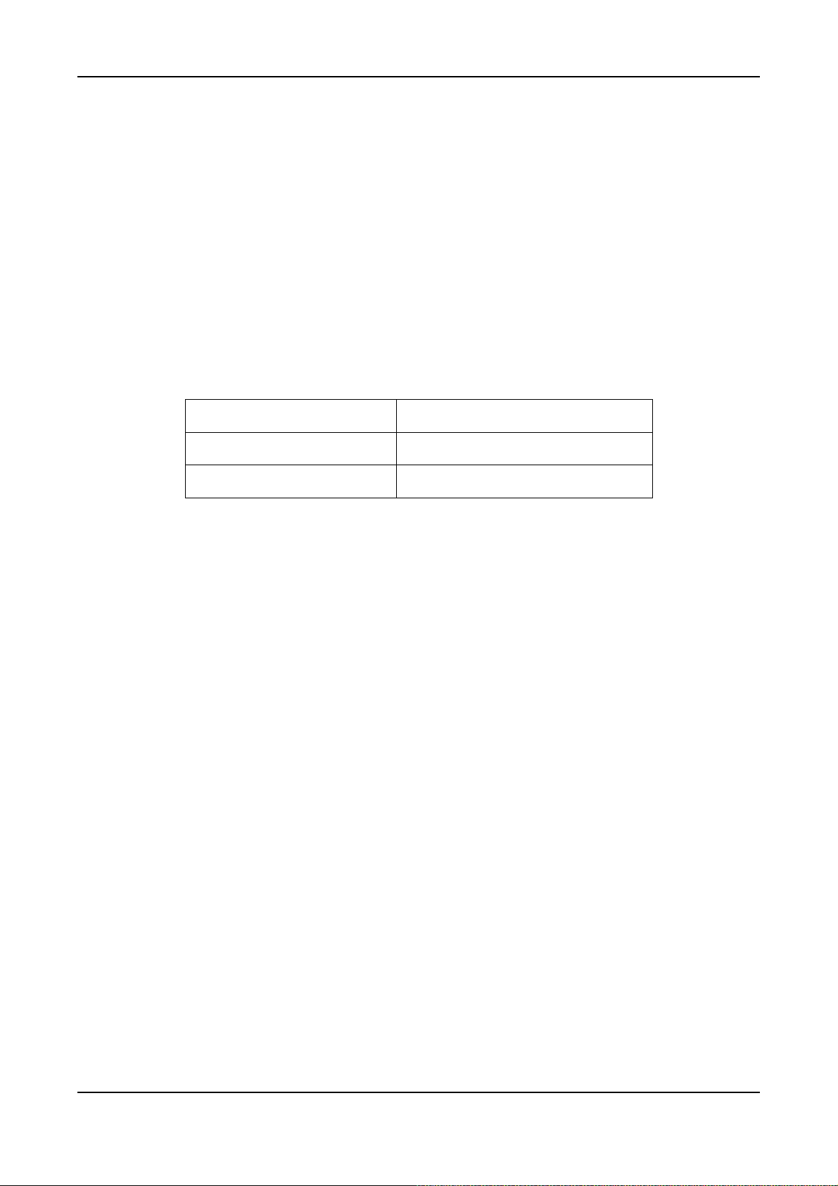
On the front panel you can find two Ethernet ports, a console port, LED status indicator and the port special for
CDR which can record the detailed data of the calls for accounting and statistics.
5.1.2. Front Panel
Alarm
Power
VTG3306
Console
CPU/Act
Time server
9600 8N1
CDR
Link/Act
100Mbps
PC
LAN
IMD
MDI-X
VTG3300 Front Panel
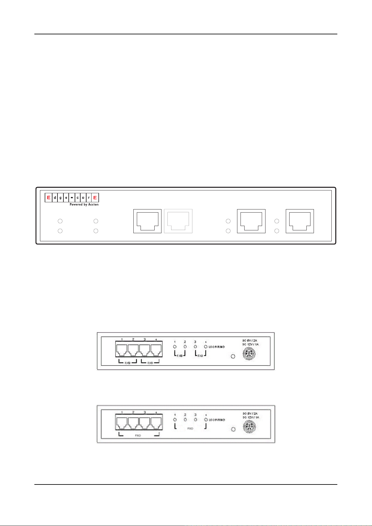
5.1.3. Rear Panel
There is a button on the rear panel of VTG3300 for special maintenance. Please don’t touch this button under
normal operation.
VTG3306A Rear Panel
VTG3306C Rear Panel
8
Page 11

VTG3300 Series user guide
(
5.2. LED Indicator
Label LED Description
10/100 Ethernet
Port Information
Device
ON Network Linked Up Link/Act
FLASH Sending/Receiving data packets
100Mbps
LOOP/ RING
Power ON Power supply normal
Alarm ON Errors detected when auto HW
FXO)
ON Transmission Rate is 100Mbps
OFF Transmission Rate is 10Mbps
ON Off Hook, loop current detected LOOP/ RING (FXS)
FLASH Ring signal sending
ON Answered, loop current detected
FLASH Ringing
diagnostics ran:
FXO Error detected or circuit break
ON CPU in normal operation CPU/Act
FLASH CPU is Running
ON Able to access to Time Server
Time Server
FLASH Trying to access to Time Server
OFF NOT able to access to Time Server
9
Page 12
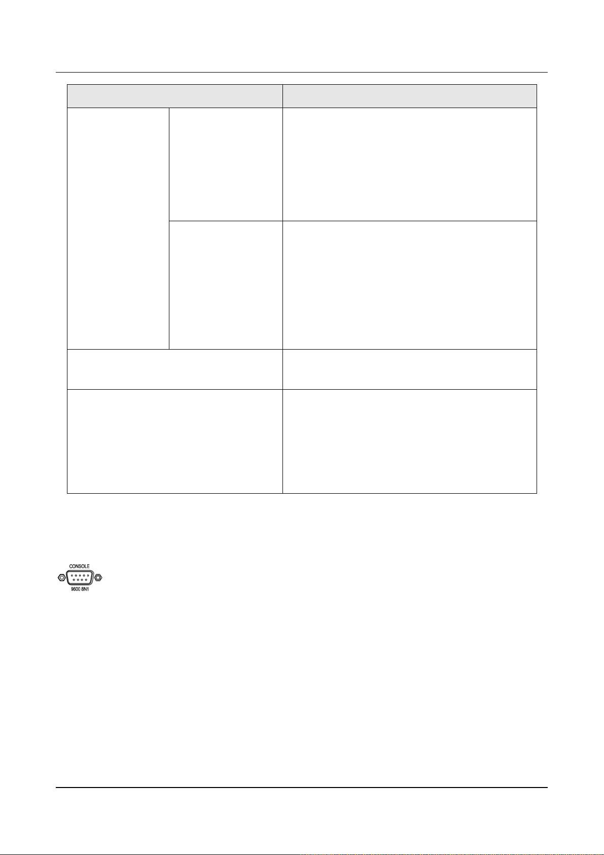
5.3. Connectors
Terminal Label Description
Voice
FXS
For analog phone set or FAX machine
FXO For public lines or trunk from PSTN Operator
To LAN (MDI-X) RJ-45 MDI-X terminal, for LAN Network
To PC (MDI) RJ-45 MDI terminal, for PC
RJ-45 CONSOLE For system console
10
Page 13
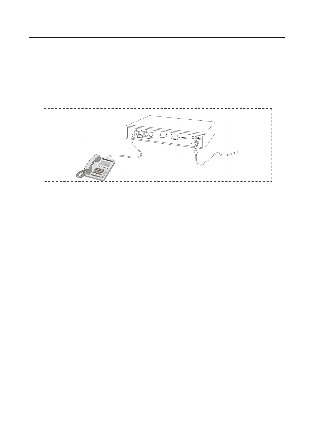
6. Basic Installation and Configuration
6.1. Phone Set Connection
Example : VTG3306A
6.2. Personal Computer Connection
VTG3300 Series user guide
Example : VTG3306C
There is a console port on the panel of VTG3306C. Plug the attached Console cable into the console port and
connect it with PC on the other side.
11
Page 14
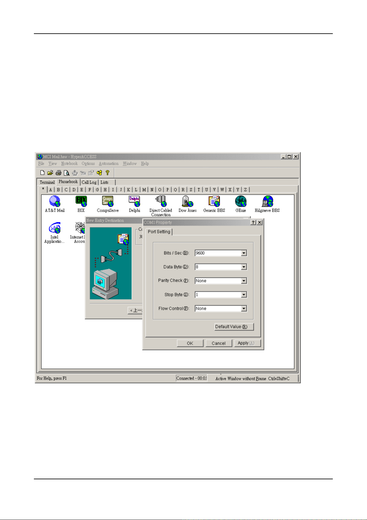
6.2.1. Configuration of Parameters for Console
After connecting the PC to VTG3300 via a RS-232 cable, Power on the PC and configure the PC parameters
as following:
Speed : 9600
Data Byte : 8
Parity Check : None
Stop Byte : 1
Flow Control : None
12
Page 15

VTG3300 Series user guide
7. Configuration of Parameters for Function and Web
Management Page
7.1. Steps for Configuration
7.1.1. General
7.1.1.1. VTG3300
(1) Connect the Console Terminal to VTG3300 Console port by RS-232 cable.
(2) Configure the parameters of Console Terminal. Please refer to Section 6.2.1Configuration of
Parameters for Console.
(3) Set Region ID and restore to the default value. Please refer to Section 7.1.2 Configuration of
Regional ID.
(4) Configure a fixed IP address by using the System Console ( or use the default IP address
192.168.0.2) and the password (e.g. 123) to enter the Web Management Page. For security reason,
please configure the password for verification when entering the Web Management page. Refer to
Section 7.1.3 Configuration of IP and 7.1.5 for configuration Password for Web Management Page.
(5) Connect PC to the network port labeled “To PC” on VTG3300 by LAN cable. The Indicator of
LNK/ACT will be ON if the connection is working normally.
(6) Set IP address of PC to the same subnet as IP address of VTG3300. For example, the default IP
address of VTG3300 is 192.168.0.2 , then you may set 192.168.0.3 as the IP address of the PC.
(PC re-start may be required).
(7) Run the Broswer, enter the IP address of VTG3300 and then press ENTER key.
(8) In the window , USER ID and PASSWORD will be prompted. Enter “WEB” (all capital letter) as
USER ID and the password you configured (e.g. 123), press ENTER key. Now you are entering
the Home page of the Web Management page.
(9) On the Web Management Page, set the Region ID, Area Code, Phone Number, UDP port and other
features. Please refer to Section 7.2.1 Configuration of Phone Number via Web Management.
(10) If you like to use DHCP or PPPoE services, you may set the parameters from Web Management
Page or via Console terminal and restart VTG3300. Please be noted, new dynamic IP address will
be applied after restarting. It causes the problem to enter the original Web Management Page. You
have to check the new IP address from the Console terminal and enter the Web Management page
by this new IP address.
(11) When all of the parameters had been configured, connect VTG3300 to Internet. The system will
start after the indicator Time Server turns ON.
13
Page 16

7.1.2. Configuration of Regional ID
The default value of VTG3300 series product is dependent on the location of purchase order. Please check if
the Region ID is for the country where VTG3300 will be operated. From the label located at the bottom of the
box, you may find the default value of Region ID, for example, “43”, the Region ID of Taiwan, is set as default
value. If the Region ID is correct, skip to the next step, otherwise change the Region ID. Please refer the
Section 12 Region ID to Telecom Country code.
The Instructions below showing how to set Region ID from Console terminal; using Telnet can also follow the
same instructions.
(In the example, the Region ID is changed to 07 for China)
Voice Gateway>enable
Voice Gateway #configure
Enter configuration commands, one per line. End with CNTL/Z
Voice Gateway (config)#regional_id 07
Voice Gateway (config)#exit
Voice Gateway #delete nvram
This command resets the system to factory defaults
All system parameters will restore to their default factory settings. All static and dynamic addresses will be
removed.
Reset system with factory defaults, [Y]es or [N]o? Yes
Attention :
1. After Changing the Region ID, the system has to be reset to the default value. Therefore this step should
be done first.
2. In case the IP address is being set, the following instruction may keep the IP address unchanged after
reset :
“delete nvram keep_ip”
7.1.3. Configuration of IP
An IP Address is required for the VTG3300 series product. How to get the IP address depends on the network
configuration to which the gateway will be connected. Please refer the following table for the network
configuration and define the IP address before doing system configuration. If fixed IP address will be used,
you have to apply for Internet service from Internet Service Provider (ISP) to get an available IP address.
DHCP, which is not recommended, or PPPoE, which is provided by most of ADSL ISP, may be used for this
gateway. In the following table, please find the information required for different network configurations.
14
Page 17
VTG3300 Series user guide
IP Network Configuration Information Required
Fixed IP Address
DHCP Please contact your MIS personnel. Using DHCP is not
PPPoE
Public IP address IP address
Subnet mask
Default Gateway
Notes: Usually the IP address is assigned by the ISP to
avoid conflict with the other equipment.
Private IP address IP address
Subnet mask
Default Gateway
Notes: IP Sharing is required for private IP address. In
the IP Sharing environment, IP address of VTG3300
has to be set as a virtual Server
recommended
Account Number
(Applied to most ADSL service)
You may perform the IP setting via System Console, then enter the Web Management page to perform the
other settings.
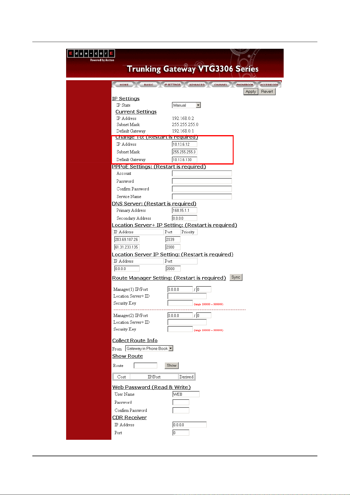
7.1.3.1. Configuration of IP Address via System Console
Configuration via System Console
(In this example)
IP will be 10.13.6.21、
Subnet mask is 255.255.255.0、
Default Gateway is 10.13.6.130)
Voice Gateway>enable
Password
Notes: Information is assigned by the ISP, please
contact your ISP if you don’t know or you forget the
account number.
Voice Gateway #configure
Enter configuration commands, one per line. End with CNTL/Z
15
Page 18

Voice Gateway (config)#ip state user
Voice Gateway (config)#ip address 10.13.6.21 255.255.255.0
System need to restart
Voice Gateway (config)#ip default-gateway 10.13.6.130
Voice Gateway (config)#exit
Voice Gateway #restart
This command resets the system. System will restart operation code agent.
Reset system, [Y]es or [N]o? Yes
7.1.4. Modify the Configuration via Web Management Page
On VTG3300 series Web Management Page, select folder “IP SETTINGS”
16
Page 19
VTG3300 Series user guide VTG3300 Series user guide
17
17
Page 20

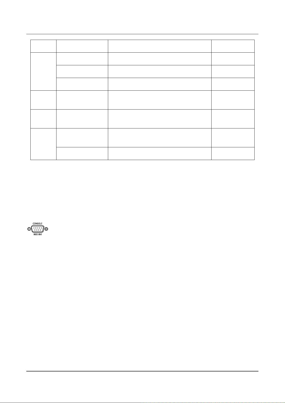
y
Group Field Descriptions Default Value
IP Settings
IP State
Current Setting
Change To
The type of IP Address :
Manual:User enters the assigned static IP
address
Auto(DHCP):D
namic IP address from DHCP
server
PPPoE:Through PPPoE to get the IP address
from ISP. Please fill in the account information
under PPPoE Settings, if PPPoE is selected.
Display the current setting: IP information,
including IP Address, Subnet Mask and Default
Gateway. (Display only)
Enter the information to be updated :
1. IP Address
2. Subnet Mask
Manual
192.168.0.2
255.255.255.0
192.168.0.1
PPPoE
Settings
Server
Account
Password
Confirm Password
Service Name
Primary Address
3. Default Gateway
(IP State must be set to “Manual”)
After you have filled out these parameters, click
“Apply” button to activate the updated values.
Then Warm Start the system.
PPPoE account, provided by ISP
PPPoE password of account
PPPoE password reconfirmed
Service Name of PPPoE account, provided by
ISP. At this moment, it is not required for most of
ISP, only a few exceptions.
IP Address of the Primary DNS server. The
default value is configured in advance,
depending on the region of shipment.
168.95.1.1 is default for Taiwan region.
Blank
Blank
Blank
Blank
168.95.1.1 DNS
Secondary Address
IP Address of the Secondary DNS server.
18
Blank
Page 21
VTG3300 Series user guide
Group Field Descriptions Default Value
WEB
Password
Collect
Route Info
Show
Route
Receiver
User Name
Password
Confirm Password
From Gateway in Phone Book
Route
IP Address
Port
User name of Web Management Page
Password to enter the Web Management Page
Re-enter the Password for reconfirmation
Enter the country code followed by the area
code. Press Show.
Enter the IP address of the remote PC or CDR
Receiver
Enter the port of PC or CDR Receiver
7.1.5. Configuration Password for Web Management Page
WEB
Blank
Blank
Blank
0.0.0.0 CDR
0
Before entering the Web Management page, for security reason you have to set the password. The password
consists of any numeric or alphabetic characters combination and is less than 6 characters. Please be noted
that VTG3300 always requests the Password to enter the Home Page of WEB Management, no exceptions.
Setting Password by system console
(The password is set to 123 in this example)
Voice Gateway >enable
Voice Gateway #configure
Enter configuration commands, one per line. End with CNTL/Z
Voice Gateway (config)#password web_write password 123
Voice Gateway (config)#exit
7.2. Configuration the Basic Parameters via Web Management Page
Start the Browser, enter the IP address of VTG3300 and press ENTER. The window will pop out requesting
19
Page 22
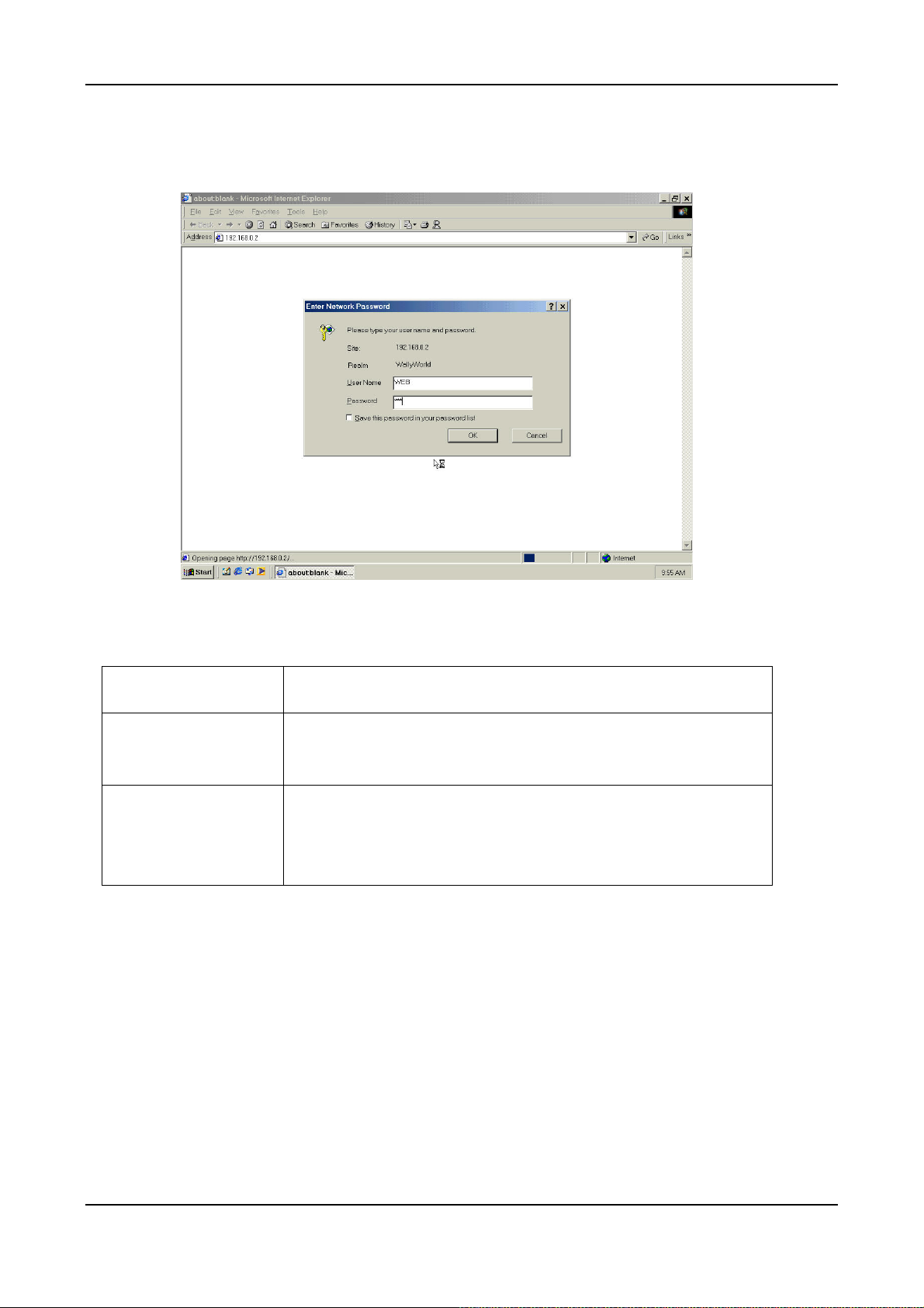
User ID and Password. Enter “WEB” (all capital letters) as User ID and the password as set before, and then
click OK. The home page of Web Management will be displayed.
Some basic parameters of VTG3300 have to be set in order to perform the basic operation. The basic
parameters include:
Items Description
Area Code
Area Code of Telecom area, e.g. 2 for Taipei
Notes : Area Code 2 for Taipei; 7 for Kaohsiung;
Phone Number
Phone Number of VTG3300, e.g. 82261111. You can make an IP-phone
call for this VTG3300 from another Gateway by dialing this number.
Use the same number as the public phone number connected to FXO
port, i.e. the general phone number
After finishing the setting of the previous basic parameters, the following functions are now workable:
The extension lines of the gateway can be connected to each other.
Dial “9” to seize the line for PSTN calls.
7.2.1. Configuration of Phone Number via Web Management
To set Area Code and telephone number, go to Web Management page, select “BASIC” then find field under
“My Phone Number”, enter information then press Apply.
20
Page 23
VTG3300 Series user guide VTG3300 Series user guide
21
21
Page 24
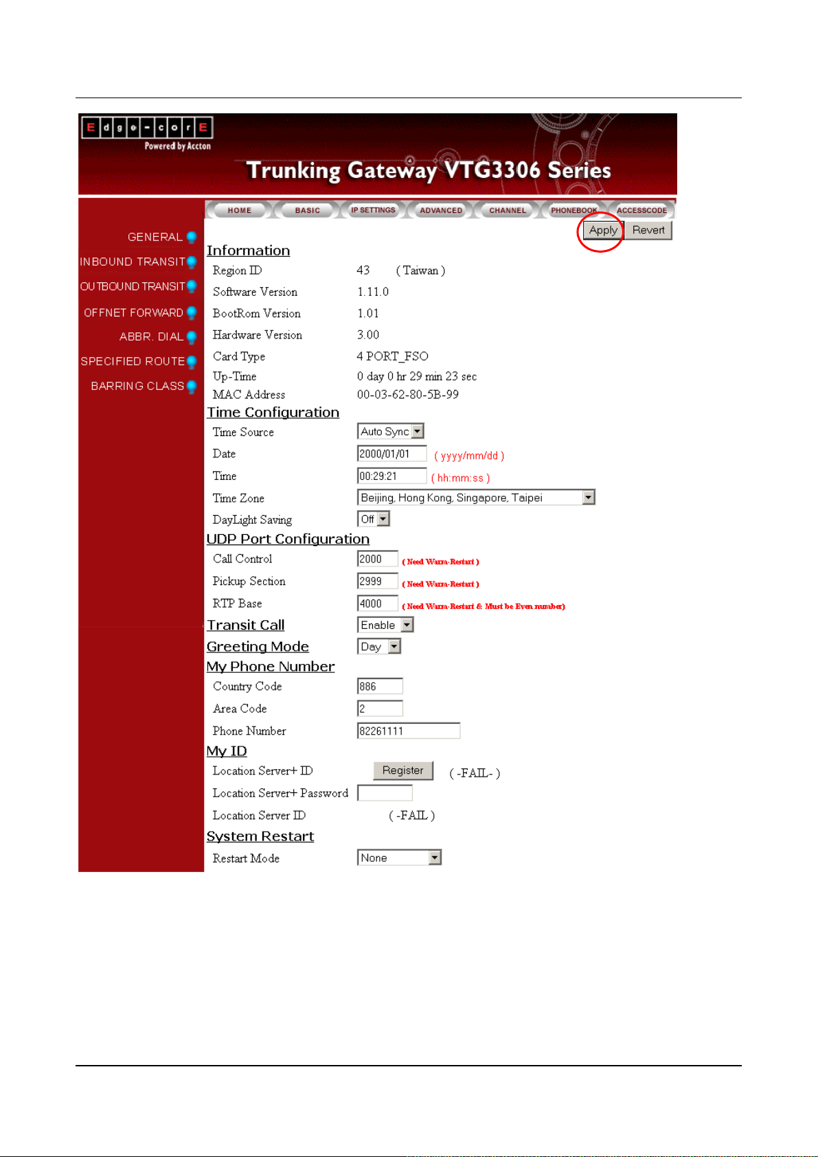
7.2.1.1. General Parameters
Group Field Description Default Value
Information
Time
Configuration
Region ID
Software Version
BootRom Version
Hardware Version
Card Type 1 (S1)
Card Type 2 (S2)
Up-Time
MAC Address
Time Source
Displays the Region ID (Display Only)
Displays the Software Version (Display Only)
Displays the BOOT ROM
(Display Only)
version
Displays the Hardware
(Display Only)
Version
Displays the card type of the
(Display Only)
1st interface card
Displays the card type of the
(Display Only)
2nd interface card
Displays the elapsed time
(Display Only)
since last start
Displays the MAC address of
(Display Only)
this equipment
Select the method to synchronize the system’s
date and time
AutoSync
AutoSync:Synchronize automatically
Manual:Entere manually
Date Enter the date manually, valid only if “Manual”
is selected in Time Source,
Format yyyy/mm/dd
Time Enter the time manually, valid only if “Manual”
is selected in Time Source,
Format hh:mm:ss
Time Zone Select the time zone which the system is
located
DayLight Saving Select for daylight saving
ON:daylight saving applied
OFF:daylight saving not applied
Blank
Blank
OFF
22
Page 25

VTG3300 Series user guide
Group Field Description Default Value
UDP Port
Configuration
Transit Call
Call Control Defines UDP port number for packet
transmission . The number should be between
the range of 0 – 65535.
(It is activated after system has been
re-started)
RTP Base
Activate Inbound/Outbound Transit
Defines UDP port number for voice packet
transmission . The port number must be even
and between the range of 0 – 65534.
(It is activated after system has been
re-started)
Enable:
Activates Inbound Transit and Outbound
Transit
Disable:
Shuts down Inbound Transit and
Outbound Transit
2000
4000
Enable
Greeting Mode
My Phone
Number
System
Restart
Selects the Greeting Mode
Day:Greeting of office hours is activated
Night:Greeting of off duty is activated
Country Code
Area Code
Phone Number
Restart Mode Select Restart Mode for the gateway
Enter the Country Code of the location where
the system is. (e.g. 886 for Taiwan; 1 for
America)
Enter the Area Code of the location where the
system is. (e.g. 2 for Taipei)
Enter the PSTN telephone number connected
None:Don't restart system
Cold Restart:Cold restart system
Warm Restart:Warm restart system
Day
(Country Code
by Region ID is
displayed)
Blank
Blank
None
23
Page 26

7.3. Configuration of Features
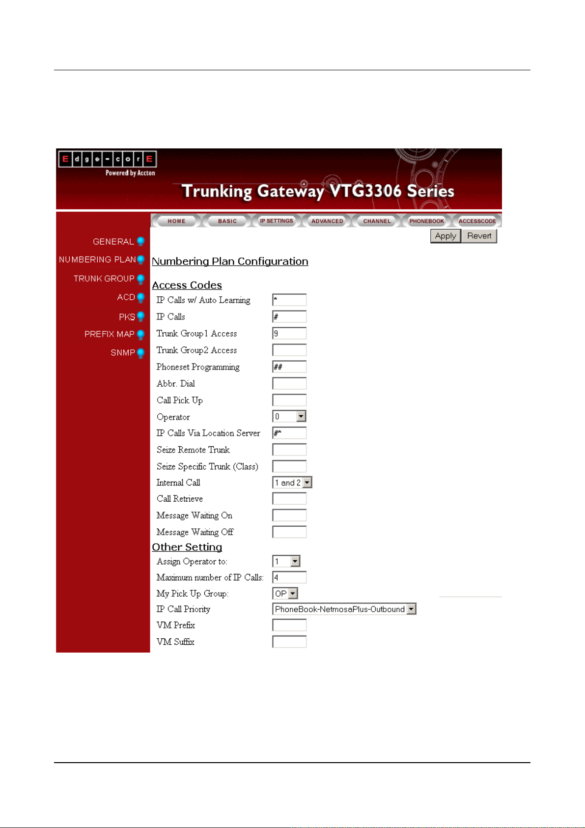
7.3.1. Numbering Plan
The numbering plan for VTG3300 defines the access code for each kind of service and the manner of dialing.
These codes will be applied often, and therefore the code should be simple, easy to remember, and unique.
Prefixes of equipment should be put into consideration to prevent conflict. For the prefix of equipment, please
refer to section 7.3.3 Prefix Map Table.
The access code consists of any combination of 0 ~ 9, * , and #; and
Total length must be less than 6 characters.
The first character can not be 0 , 1 , or 2.
If an access code is defined, you can define another access code by this code followed by one
extra character, only one character is allowed. For example, “9” is defined as Trunk Group Access
Code, then “91” or “92” may be defined as another access code, but “921” or “9112” may not be
defined as an access code.
Code can not be used if it has been defined as a prefix in Prefix Map Table.
The default access codes are listed for your reference.
Items Access Code
IP Calls w/ Auto Learning *
IP Calls #
Trunk Group 1 Access 9
Trunk Group 2 Access 8
Phoneset Programming ##
Abbr. Dial *2
Call Pick Up *3
Operator Code 0
Seize Remote Trunk *9
24
Page 27
VTG3300 Series user guide
7.3.1.1. Numbering Plan WEB parameter
From the Web Management Page, select folder “ADVANCED”; select “NUMBERING PLAN”
25
Page 28
g
Group Field Description Default Value
Access
Code
IP Call w/ Auto
Learning
Access Code to Make IP Call, and
learning will start automatically when
number is not found from Phone Book
IP Calls Access Code to Make IP Call
Trunk Group1 Access Access Code to Fetch trunk from trunk
group 1
Trunk Group2 Access Access Code to Fetch trunk from trunk
group 2
Phone set
Programming
Access Code to start configuration of
gateway via Phone set
Abbr. Dial Access Code for Abbreviated dialing
Operator Access Code to Connect to Operator
Seize Remote Trunk Access Code to Seize the Trunk
roup
of a remote gateway, but has to obtain
the permission first. That means, in
the seized side, the information of the
other side is defined in the list of
Outbound Transit, the Trunk Call
Allowed is set to True, and Trunk
Group is set to Enable.
*
#
9
Blank
##
Blank
0
Blank
Dialing Method : <Seize Remote
Trunk Access Code> + <Country
Code> + <Area Code> + <#>。
For example, there is a system in
Taipei, and a system in Shanghai. You
may dial the access code of “Seize
Remote Trunk”, e.g. *9 8621# , from
the extension line in Taipei to seize
the trunk of Shanghai
26
Page 29

VTG3300 Series user guide
Group Field Description Default Value
Seize Specific Trunk
(Class)
Access Code to Seize the Specific
Trunk of the remote gateway, but you
Blank
have to obtain the permission first.
That means, in the seized side, the
information of the other side is defined
in the list of Outbound Transit, the
Trunk Call Allowed is set to True, and
Trunk Group is set to Enable.
Dialing Method: <Seize Specific
Trunk Access Code> + <Prefix> +
<Class ID> + <#>.
Internal Call An incoming call to FXO will hear the
1 and 2
greetings first. System will check if the
code you dial is an internal call or not
before searching the entries in the
Prefix Map. By default, the extension
number is starting from 1 to 2, system
will handle this call as an internal call
if 1 or 2 is dialed first.
Here you may change the way to :
- 1 and 2: the way is same as before
- 1 only: only 1 will be treated as an
extension number, otherwise search
from the Prefix Map table.
- 2 only: only 2 will be treated as
extension number, otherwise search
from Prefix Map table.
- None: all numbers dialed will be
searched from the Prefix Map table. It
is a wrong number if it is not found
from the Prefix Map table.
27
Page 30

y
Group Field Description Default Value
Assign Operator to Assigns an extension line as the
1
Operator. If operator is not assigned in
the gateway, set to N/A.
Maximum number of
IP Calls
The maximum number of IP Call can
be made. The default value is the
4 Other Setting
number of extension lines. It is
recommended to plan it depending on
the bandwidth.
IP Call Priority
Configure the phone number
searching priority for outbound call.
PhoneBook-Outb
ound
Please refer to related chapter of
PhoneBook, Outbound,
1.PhoneBook-Outbound:The s
stem
search phone number according to
this sequence.
2.PhoneBook -Outbound:Change to
different sequence
7.3.2. Configuration of Ext. Line and Trunk (Channel)
The last 2 digit of the model name of VTG3300 series product presents the number of ports equipped.
If you would like to display the information of the extension lines, enter the folder “CHANNEL” of the Web
Management Page, and select “SUMMARY”, a summary page for all ports of extension will be displayed. From
the summary page below, it shows the information using VTG3300A (2FXS + 2FXO). The extension numbers
are from 11 to 12 and the port 1 (11/OP) is set as operator.
From the Web Management Page, select folder “CHANNEL”; select “SUMMARY”
28
Page 31

7.3.2.1. Summary Description
VTG3300 Series user guide
Group Field Description
SUMMARY Channel Sequence number of port 1~16 (Display only) 1~16
I/F Type Type of interface (Display only) FXS / FXO
Operating Status Displays the status of operating (Display only) Enable
T.38 Support T.38 or not (Display only) NO
Shows the characteristics (Display only) Trunk or Opr
Group
Ext. or Trk. Class
FXS : If Operator Group ( Yes/No )
FXO : number of the trunk group (1/2 )
Displays the defined extension
number. The extension line that
has joined to operator group will
also show "/OP"
FXO: Shows "Trunk Class ID"
(Display only) -/11~26
Default Value
/NA
-/Yes
-1
0/-
Barring Class Displays the Barring Class (Display only) 0
7.3.2.2. Channel WEB Parameter
To configure the extension line, enter the folder “CHANNEL” of the Web Management Page, select the page
“CONFIGURATION”, enter the channel to be configured then click button Apply
From the Web Management Page, select folder “CHANNEL”; select “CONFIGURATION”
29
Page 32

30
30
Page 33

VTG3300 Series user guide
7.3.2.3. Configuration Parameters
Group Field Description Default Value
Information
Channel
Extension Number
Port Type
Port State
Current State
Selects the port number to be configured
The extension number that is defined to this
selected port
Displays the type of port (Display only)
Phone : FXS interface for phone set or FAX
Line : FXO interface for telephone line
NA : Not used
Activates or shuts down all functions of
selected port
Enable: Activates all functions to selected port
Disable: Shuts down all functions to selected
port
Display the current status (Display only)
1
11
Enable
Enable
Do Not Disturb
T.38 Fax Relay
Device Capacity
Current Quantity
Support T.38
Voice Input Gain
Enable : Selected port is enabled
Disable: Selected port is disabled
When DND function is enabled for this
channel, only outgoing calls are available and
incoming calls to this channel will be busy.
Enable/Disable
Displays the total port number allowed for FAX
(Display only)
Displays the port number that has been
configured for FAX (Display only)
Enables T.38 support on selected port
Yes: Support
No: No support
Enter Input Gain
Disable
16
0
NO
0 dB
31
Page 34

Group Field Description Default Value
Output Gain
Counter
Enter output Gain
Counter for FXO Loop Error
Error Counter
Clears the counter
Enables or disables the function “Call
Call Forward
Clear Counter
Control
Forward”
Forward-Disable: Disables the function.
Forward-All Calls: Forwards all calls.
Forward-Busy: When the FXS is busy, calls
will be forwarded.
Forward-Busy-Slave:
calls will be f
busy and is also configured as
Forward-Busy-Slave. The call will continue
forwarding to the next configured phone number.
No Answer-Forward: When there is no answer
for this FXS port, the call will be forwarded to a
specified destination
0 dB
0 FXO Loop
Disable
When the FXS is busy
orwarded. If the destination is also
Forward to
(Gateway Phone
Number)
Busy/NoAnswer-Forward: When there is no
answer or the line is busy for the FXS port, the call
will be forwarded to the specified destination
Forwards the call to the Gateway you
specified. The entered telephone number
must contain a full telephone number,
including country code and area code.
If the "Offnet to" number is also configured,
the call will call to PSTN via the gateway that
the phone number is configured.
FXS Port can be configured as “Forward to”.
FXO port can be configured to forward the call
to a FXS port.
Blank
32
Page 35

VTG3300 Series user guide
Group Field Description Default Value
Offnet to
(Offnet Phone
number)
Barring Class ID
Outbound
Transit Control
Privilege
Forwards IP calls that are coming (or
forwarding) from another gateway to PSTN.
The Offnet to number here is to call to PSTN.
For example, the local gateway is located in
Taipei. The number will be forwarded is
located at Shanghai, phone No. 21-6445-1111
(this No.+ country code is configured as
"Forward to" No. 86-21-6445-1111) and if you
want to make a PSTN mobile phone call to
Shanghai No. 1360567888, so you configured
1360567888 as "Offnet to" No here.
The “Permitted Phone Number for Offnet
Forward” in Shanghai should be configured to
“1360567888”.
Enter the Barring class for selected port
Defines the privilege for Outbound Transit
calls
Blank
0
Disable
Join Operator
Group
Yes/ No
Disable: Outbound Transit call is not allowed
Local: Outbound Transit call are local calls
only
Toll: Outbound Transit allows long-distance
calls within the country.
International: Outbound Transit allows
international calls.
The local calls, toll calls, or international calls
are judged from the phone number defined in
the gateway.
Defines whether to join into Operator Group or
not.
Yes: joins Operator Group to behave as
Operator
No: does not join
Yes
33
Page 36

y
Group Field Description Default Value
Join Trunk
Group ID Defines which trunk group to be joined
Group
1: Trunk group 1 is joined
2: Trunk group 2 is joined
Trunk Class ID Selects Trunk Class ID for FXO port. Default
Battery
Reverse
value is 0. There are 0 to 15 for selections.
Control Battery Reverse is a mechanism for traditional
PBX to judge ON hook or Off hook status.
ON: Battery reverse is enabled
OFF: Battery reverse is disabled
Soft Key
Soft Key String Defines the character string of softkey. When
the softkey is triggered, the string will be
dialed. The maximum length of a string is 22
digits.
Trigger Mode Chooses the mode to trigger the softkey:
Key Press: If the digits dialed matches
with an
one of the digits defined in Trigger
Digits, the softkey is triggered and the
number defined in softkey string will be
dialed.
Auto: For FXS, it is triggered when
phone-set in off hook status. For FXO, it is
triggered when line is ringing.
N/A
0
FXS : OFF
Blank
Key Press
Trigger Digits Defines the digits to trigger the softkey
Blank
e.g. If trigger digits are 123, softkey will be
triggered if 1, 2 or 3 is dialed.
Append Trigger Digit Defines if the trigger digits will be appended to
Not Append
the softkey sting as the last digits when dial out
Not Append: Not appended
Append: Trigger digits are appended.
Marks the selection. Check box and then click
Statistics Reset
Apply to reset the traffic statistics.
34
Page 37

VTG3300 Series user guide
Group Field Description Default Value
Counter Type
Successful Outgoing Call
Incoming Call
Successful Incoming Call
Busy Time(sec): Total time used on the port
7.3.3. Prefix Map Table
In the VTG3300 series, you can define a prefix ID for each VTG3300 system in the Prefix Map Table. Then you
can connect to these other systems by dialing the prefix ID defined for that equipment.
Definition
There are three fields in the Prefix Map Table:
1. Prefix ID
The prefix ID for other equipment, maximum length is 6 characters.
Call Attempt: Volume of calls
2. Phone Number
The phone number of other VTG3300 devices.
3. Type: There are two types: iPBX or Phone
iPBX is used for the VTG3300 series
If iPBX is defined in Type, system will use Prefix ID + 2 digit extension number (Prefix ID + Ext No.), or
Prefix ID + “0” (Prefix ID + 0) to make calls. How it works: The system will dial Prefix ID’s corresponding
phone number and then the 2 digit extension number of the remote system or 0 for operator if it is
defined.
If Phone is defined in Type, the system will call using the Prefix ID number’s corresponding phone
number.
The Prefix Map Table is only adapted to the trunks or extension lines of its own system. It can not be shared by
the other equipment. That means that each equipment should define its own Prefix Map Table.
35
Page 38

If you would like to connect to a T.38 FAX port, you must define “phone No. + *” in the Prefix Map Table.
For example Prefix number 301:
Prefix Phone Number Type
300 886282263139 Phone
301 886282263139* Phone
Dial “300” from a FXO or FXS port and the system will always search for a Non-T.38 port as the destination.
Dial “301” and the system will check if T.38 is supported by the calling side. If yes, the system will search for a
T.38 port as the destination. If not found, it will search for a Non-T.38 port.
Attention:
If there are two VTG3300s that would like to dial each other by using Prefix + extension number, the prefix
number defined for each VTG3300 must be defined and identical. If there are more than 3 units that would like
to dial each other, the prefix number for each equipment must also be defined and identical.
7.3.3.1. Restrictions in Prefix Map Table
Prefix Map Table is part of a Numbering Plan, any conflict or duplication is not allowed. Please note these
restrictions.
Avoid defining prefix numbers starting with the digits “1” and “2”. If you have to use numbers starting with
digits “1” or “2”, please refer to Session 7.3.4 Internal Call in Numbering Plan. It may cause confusion if
such numbers are present in extension numbers or prefix numbers.
Avoid defining prefix numbers starting with the digit “9”. In the normal numbering plan, “9” is the default
value for the Access Code of fetching a line from trunk group 1.
Avoid defining prefix numbers starting with the digit “0”. In the tradition telephone numbering plan, “0” is
defined as the starting digit for accessing long distance call or international overseas calls.
The maximum length of Prefix code is 6 characters. In principle, you cannot define a new prefix number
starting with the number that has been defined previously. For example, “33” is defined as a prefix
number, then any numbers starting with “33”, like “330”, “3312”, can not be defined as a prefix number.
Of course, “31”, “32”, or “34” are OK. Another example, “555” is defined previously, then “5551” or
“55522” can not be defined as a prefix number, but “551” or “552” or “553” …etc. is OK.
36
Page 39

VTG3300 Series user guide
7.3.3.2. Web Page for Prefix Map
From the Web Management Page, select folder “ADVANCED”; select “PREFIX MAP”
37
Page 40

Group Field Description Default Value
Network
Operator
Prefix Map
(Display Only)
Prefix Enter the prefix number of equipment that will
Blank
be assigned as Operator. Normally the
Operator of a system will be connected if the
Access Code for Operator (default is “0”) is
dialed. If the Operator of a system is set to
N/A, the call will be transferred to the
Operator of another system whose prefix
number is assigned here.
e.g. the Prefix Map Table of own system :
prefix phone type
33 886282268888 iPBX
Enter 33 in the Network Operator field if you
want to assign the equipment as operator.
Maximum The maximum number of equipment that can
600
be entered.
Entered The number of equipment has been entered 0
Max Prefix Length The maximum length of a Prefix number 6
38
Page 41

VTG3300 Series user guide
Group Field Description Default Value
Add/Modify Entry Add/Modify a Prefix number
Prefix:
Enter the Prefix number of other equipment,
maximum length is 6.
Phone Number:
Enter the phone number of the VTG3300 or
the Gateway that prefix is assigned to.
Type:
Type ( iPBX / Phone ) indicates if the prefix
number is assigned to VTG3300 series
products or other products. iPBX is selected if
it is assigned to a VTG3300 series product.
If the type is iPBX, the system will start to
create a call path after dialing the prefix
number + 2 digit extension number (prefix ID
+ Ext No), or the prefix number plus “0” (prefix
ID + 0). Actually, the corresponding telephone
number of the equipment defined in the Prefix
Map Table is sent out. In the later case, “0”
will be treated as the access code for the
Operator if operator is defined in the system,
otherwise the “0” after the Prefix number will
be ignored.
Blank
Phone Number
Search
If the type is Phone, the system will start to
create the call path after dialing the Prefix ID
number.
Delete Entry Deletes the Prefix number Blank
Delete All Entries Deletes all Prefix numbers No
Prefix Enters the Prefix to be searched Blank
Phone Number Displays the phone number of equipment
defined by the searched prefix
Type Displays the type of equipment defined by the
searched prefix.
39
Blank
Blank
Page 42

7.3.4. Internal Call
Each FXS port in the VTG3300 series can be an extension line of PBX; an extension number is a number from
11 to 26 only. FXS extension line can be connected to by dialing the extension number or prefix number
followed by the extension number.
FXS lines in the VTG3300 series can dial to the following products directly:
Extension lines of another VTG3300 and VTG3300 gateways on the remote side.
For the dialing procedure, please refer to the following table:
Called side Dialing from Calling side
The extension line of another
VTG3300, VTG3300 gateways
on remote side
Method 1: <IP Calls Access Code > + International Access Code +
telephone number of VTG3300 + Extension number + “#”
e.g. # 002862164451111 22 #
Method 2: Prefix + Extension number
e.g. 3322; 33 is the prefix of VTG3300 of called side
7.3.5. Dial to PSTN line
7.3.5.1. Access Trunk Group
All FXO ports are separated into two trunk groups: Trunk Group 1 and Trunk Group 2. Any extension line will
access a free trunk from Trunk Group 1 if the Access Code for Trunk Group 1 is dialed, or from Trunk Group 2
if the Access Code for Trunk Group 2 is dialed. The access sequence is from the last ports upward, i.e. 16,
then 15, 14, then 13.
All FXO ports and Trunk Groupswill be configured via the Web Management Page, folder “CHANNEL”, please
refer to Session 7.3.2 Configuration of Ext. Line and Trunk (Channel).
I. Configuration of Trunk Group Access Code
From the Web Management Page, select folder “ADVANCED”; select “NUMBERING PLAN”, via this page to
configure the Access Code for Trunk Group.
40
Page 43

VTG3300 Series user guide
Enter the digit in the field “Trunk Group 1 Access” to configure the Access Code for accessing the trunk group
1. It is “9” in the figure. Enter another digit for Access Code of Trunk Group 2, e,g. “8”.
Attention: The Access Code in the Numbering Plan can not cause any conflict.
II. Configuration of Each FXO to A Trunk Group
Each FXO port should be assigned to a trunk group, either Group 1 or Group 2.
From the Web Management Page, select folder “CHANNEL”;select “CONFIGURATION”. In this page, enter
the FXO port in the field of Channel and click the button Select. Then choose the trunk group 1 or 2 in the field
of “Group ID”. Please refer to the following figure:
From the Web Management Page, folder “CHANNEL” and select “CONFIGURATION”
7.3.6. Seize Remote Trunk
Taipei
Dial 9
PSTN
FXO
VTG3300
IP
FXS
Dial *9 8621#
…
FXO
FXS
PSTN
VTG3300
Country Code: 86
Area Code: 21
Shang hai
…
41
Page 44

The VTG3300 can access its own trunk by dialing the Trunk Access Code “9”. In addition, it can seize the
remote trunk by using Seize Remote Trunk Access Code.
Dialing Method:
<Seize Remote Trunk Access Code> + <Country Code> + <Area Code> + <#>
Example:
There are two VTG3300s, one in Taipei (8862), and the other one in Shanghai (8621). On the Shanghai side,
the VTG3300 is configured to give permission for Taipei to place an Outbound Transit Call. The Trunk Call
Allowed is set to TRUE for Country Code = 86 and Area Code = 21. On the Taipei side, Seize Remote Trunk
Access Code is configured as “ *9 ”. Under such configuration, Taipei can place a call to the Shanghai PSTN
line through the VTG3300 in Shanghai, seizing the remote trunk of the VTG3300 in Shanghai by dialing
“ *98621# ”.
I. Configuration on the Line of Own Side
Define the Access Code of Seize Remote Trunk, from Web Management Page, folder “ADVANCED” and
select “NUMBERING PLAN”
II. Configuration on the Remote Side
To give permission to own gateway to make Outbound Transit Calls, set Trunk Call Allowed to TRUE (please
refer to section 7.3.17 Outbound Transit Calls) and set the field Allow Remote Access of Trunk Group to TRUE.
From the Web Management Page, folder “ADVANCED”, select “NUMBERING PLAN.”
42
Page 45

VTG3300 Series user guide
7.3.7. Access Trunk of the Same Area
If there are no free trunks in own gateway or no trunks are connected to own gateway, you may use the
function Same Area Trunk Access to access the trunk of another VTG3300 gateway that is in the same area;
same area means the same country code and area code.
Country Code: 886
Area Code: 2
PSTN
All Busy
FXO
FXO
PSTN
Country Code: 886
Area Code: 2
Taipei
VTG3300
VTG3300
Taipei
IP
Dial 9
FXS
…
Auto Seize
Same Area
Trunk
FXS
…
Dial Method:
<Trunk Access Code>
Dial Trunk Access Code “ 9 ” to access a free trunk of own gateway. The system will access the free trunk from
the other gateways in the same area automatically if no trunks are available its own gateway.
I. Configuration on the Line of Own Side
Define the field of Same Area Trunk Access to TRUE from the Web Management Page, folder “ADVANCED”
and select “GENERAL”.
II. Configuration on the Remote Side
Gives permission to own gateway to make Outbound Transit Calls. Set “Trunk Call Allowed” to “TRUE”
( please refer Session 7.3.16 Outbound Transit Calls) and set the field Allow Remote Access of Trunk Group to
“TRUE” from the Web Management Page, folder “ADVANCED” and select “NUMBERING PLAN”
43
Page 46

7.3.8. Trunk Class (0~15)
General
1. Trunk Class ID (0~15) may be assigned to every FXO port. The default value is 0.
2. By defining Trunk Class, the specific FXO port may be accessed by a remote gateway.
3. Dial Method:
<Seize-specific-Trunk-Access-Code> + <Prefix> + <Class(0~15)> + <*/#>
4. Note: The FXO port of own gateway has to give the permission of Outbound Transit to the remote
side, and set Call Allowed to TRUE, please refer to sec.7.3.18 Outbound Transit Call. If there are
several FXO ports that have the same Trunk Class ID, then access is granted from the last port
upward.
Configuration
I. Configuration of own gateway
From the Web Management Page folder “CHANNEL”, select “CONFIGURATION” page
II. Configuration of remote gateway
From the Web Management Page folder “ADVANCED”, select “NUMBERING PLAN” page.
44
Page 47

III. Example
VTG3300 Series user guide
Channel 1
Class 1
CO
Channel 2-8
Classes 0
Prefix: 345
VTG3300
Own
IP
VTG3300
Remote
Dial “Access Code+3451#” Can
seize Channel 1
7.3.9. Trunk Group Telephony Workgroup
General
1. For accessing the specific FXO port of own gateway, each FXO port should have a Trunk Group ID
2. If the FXO port will join a Trunk Group Telephony Workgroup, the port must connect to a PSTN line.
And the functions concerning the trunk access to this port must be enabled. (e.g. Trunk Group
Access, Outbound Calls, etc.)
Configuration
From the Web Management Page folder “ADVANCED”, select “TRUNK GROUP” page:
Joining to Trunk Group Telephony Workgroup is on basis of Trunk Group ID. Therefore FXO port must have
Trunk Group ID first, and then check if this Trunk Group ID will join to Trunk Group Telephony Workgroup or
not.
45
Page 48

j
Tick Telephony Workgroup means allow remote gateway to Seize Remote Trunk or do Outbound Transit call to
seize the FXO port of this Trunk Class. If the table here is not ticked, FXO port of Trunk Class can be
accessed by Seize Specific Trunk (Class) only.
Example
Broadcast
PSTN
Class 0
All FXO ports belong to Trunk Group 1
Ports of Class 0 connect to PSTN line, and only Class 0
Class 1
VTG3300
FXO
oins Telephony Workgroup.
Dialing “9” PSTN line can be accessed.
Dialing “8”, the broadcast will be initiated if system is
properly configured.
Dial “8”
Dial “9”
46
Page 49

VTG3300 Series user guide
),
7.3.10. Call Transfer
Either Called Side or Calling side can do a Call Transfer to the extension below if they use the FXS ports of the
VTG3300
Any extension line of the same gateway
The extension line of another VTG3300 series product on the remote side
Dial Method
When you would like to transfer a call that is answered, just flash the phone set or press the Transfer key.
When you will hear the dial tone, dial the extension number.
If the VTG3300 is connected to PBX (the FXS port of VTG3300 is connect to a FXO port of PBX), it is possible
that the Flash (or Transfer) signal is unable to pass to the VTG3300. If this happens, use "#" to replace the
Flash (or Transfer) button. Please disable "Manual IP Learning" for this function. For details, please refer to
Session 7.3.23 Access Code.
Dialing Method is shown below.
Transferred To Procedure
Extension line of same
Gateway
Press Flash then dial the Extension number; or
Press Flash then dial the Prefix of own Gateway+ Extension number
Example: Flash → 14、Flash → 33 14
Extension line of
another VTG3300,
VTG3300 on the
remote side
“ * ” + Telephone number + Extension number + “ # ”
Or
Flash → “ * ” + Telephone number + Extension number + “ # ”
Or
Flash → prefix + Extension number
Example: 55 is the Prefix of remote VTG3300 (55 = 886282263368/iPBX
telephone number is 82263368, extension number is 14
Please dial
*8226336814# or
Flash → 55 14
Please adjust the flash time of the phone set to avoid from causing disconnection when flashing or transfering
call. The flash time of the phone set should be same as configuration of the VTG3300. The flash time can be
adjusted from the Web Management Page, folder “ADVANCED”. Select “GENERAL.” In the following figure
200ms is the value for the default Flash Time.
47
Page 50

Group Field Description Default Value
Flash Button Flash Time Enter the time for the “Flash” signal (or
200ms
transfer key) to be recognized by system.
7.3.11. Operator
The VTG3300 series Gateway supports several types of Operators:
DISA
Operator for own Gateway
Network Operator
When a call is coming from a trunk (i.e. FXO port) or from IP, the VTG3300 will follow the “procedure to select
Operator” in the following chart to distribute the calls to the correct type of Operator.
Parameters
The following parameters are involved in the procedure.
48
Page 51

VTG3300 Series user guide
Parameter Description Web Page
DISA PSTN Call DISA is activated automatically when call is
coming from a trunk
Enable: Activated
Disable: Shut Down
DISA IP Call DISA is activated automatically when call is
coming from IP
Enable: Activated
Disable: Shut Down
Assign Operator To Assign a certain extension line as Operator
Operator Code Access Code to access Operator
Network Operator Define the Prefix code of Network Operator Folder “ADVANCED” / Select
Folder “ADVANCED “/ select
“GENERAL”
Please refer to Section 7.3.11.3
Built-In DISA.
Folder “ADVANCED” / select
“NUMBERING PLAN”
Please refer to Section 7.3.11.4
Operator for own Gateway.
“PREFIX MAP”
Please refer to Section 7.3.11.5
Network Operator Prefix.
Join Operator Group A line to join the Operator Group Folder “CHANNEL” / select
“CONFIGURATION”
Please Refer to Section 7.3.11.4 III.
Configuration Operator Group
49
Page 52

7.3.11.1. Procedure to Select Operator
Call from
Trunk
Call from IP
DISA
PSTN Call ?
Enabled
Disabled
DISA
IP Call ?
Enabled
Disabled
Greetings
No
Op. Code
Yes
Assign
Operator To
N/A
Ext. No.
Find next OP .
from OP. Group
Available OP
in OP. Group
Ye s
Line in busy
Blank
Network
Operator
Prefix
Action by
the digit
dialed
No
Busy Tone
No
Answered
by this Ext.
Answered by OP
of Prefix
assigned
50
Page 53

VTG3300 Series user guide
7.3.11.2. Call Flow
A call is coming from a trunk by dialing the PSTN Number of a VTG3300, DISA will answer the call according
to the number is dialed.
Number Dialed Call Flow
Extension No. (11-26) Call connects to the extension line assigned
Prefix Code Call connects to other equipment assigned
Operator Code Call connects to the port assigned for Operator
IP Call Call connects to IP phone assigned
None of above Will broadcast the announcement “The number you dialed
can not be recognized”. You have 3 times to correct the
number, then the VTG3300 will disconnect the line
7.3.11.3. Built-In DISA
The DISA is built-in to each port and whenever a call is coming from trunk or from IP via Internet, DISA is
always available to broadcast the greetings. Please configure DISA if you need the Auto Attendant to deal with
the incoming call from a trunk or IP.
From the Web Management Page, folder “ADVANCED”, Select “GENERAL”
Group Field Description Default Value
DISA
Trunk Call (FXO) Trunk will be answered by DISA
Enable
Enable: Yes, broadcast the Greetings
Disable: No
IP Call If the call from IP will be answered by DISA
Disable
Enable: Yes, broadcast the Greetings
No Answer, send
greetings
Disable: No, connect to Operator directly. If
st
Operator is not defined, connect to the 1
port.
50 seconds is default value. (30 seconds is
recommended.) That means if the call is not
answered in 50 seconds, the call control goes
back to DISA.
51
50 seconds
Page 54

7.3.11.4. Operator for own Gateway
When a call is coming and the Operator Code is dialed, the VTG3300 will connect this call to the Operator.
Note: When the Operator is busy, the system will find a free extension line that is configured in the Operator
Group starting from channel 1. For better support, the seats of extension lines that are configured in Operator
Group should be not far from their seat.
Please refer to Section 7.3.11.1 Procedure to Select Operator
I. Assign Operator Port and Operator Code
Steps of configuration:
(1) From the Web Management Page, folder “ADVANCED”, Select “NUMBERING PLAN” to enter the
Page
(2) Enter/select a number in the field of “Operator”
(3) Enter/select a port in the field of “Assign Operator to” of group “Other Setting”
(4) Click button Apply
II. Operator Call Forward
When a call is coming and the Operator Code is dialed, the VTG3300 will connect this call to the extension line
of the Operator. If the Call Forward is configured on the line of Operator, the incoming call to Operator will be
forwarded to the new destination. By using this function, the Operator can be any line you like when the
company is off duty time or on holiday. The Operator can be assigned to any extension line port, and if this
port is configured as Call Forward, then any call for Operator will be forwarded.
III. Configuration Operator Group
When the Operator is busy, the system will look for a free extension line that is configured in the Operator
52
Page 55

VTG3300 Series user guide
Group, starting from channel 1 to 16. To configure the Operator Group from the Web Management Page, Click
folder “CHANNEL”, and select “CONFIGURATION” to enter the Page
Note: If an extension line is joined Operator Group and supports T.38, this line will never be selected even if all
Operator extension lines are busy.
7.3.11.5. Network Operator Prefix
I. No Operator in own Gateway, Operator is located at other VTG3300
In the VTG3300 series, the Operator line may be assigned to another gateway through the Internet. When a
call is coming and dials the Operator Code, system will search for an Operator in its own gateway. If the
Operator is set to N/A, the system will assume that the Operator is defined on another gateway. From the
Network Operator Prefix configuration, the system will find the Operator for this call. Of course, the Network
Operator Prefix has to be configured in advance.
In the following example, the Network Operator is configured on a gateway with Prefix code 81 and phone No.
886-2-8226-8881.
Steps of configuration:
(1) In the gateway’s Web Management Page folder “ADVANCED”, Select “NUMBERING PLAN” page,
in group “Other Setting”, set field of “Assign Operator to” to N/A.
(2) Configure the Prefix data of the gateway, in which Operator will be assigned, into Prefix Map Table
of own gateway.
(3) Enter the Prefix of the gateway that will be assigned as Operator into the field “Network Operator
Prefix”.
In Prefix Map table: Prefix 81 = 886282268881/iPBX
In Numbering Plan: set 81 in the field “Network Operator Prefix”
53
Page 56

A
A
No matter what type (Phone/iPBX) is assigned to the Prefix of the Network Operator, the procedure to access
network operator is same as the one for local operator.
II. Operator defined in own Gateway
When a call is coming and the Operator Code is dialed, the VTG3300 will find the Operators of its own
gateway for answering the call first. If the lines in the Operator Group of its own gateway are busy, and
another gateway is assigned as backup Operator, then system will find an available Operator from the second
gateway. If the second gateway has also assigned a third gateway as backup Operator, and all Operators of
the first and the second gateway are busy; then system will find an available Operator from the third gateway.
A Maximum of 15 gateways can be used in succession.
CO
FXO
VTG3300
FXS
VTG3300
FXS
IP
VTG3300
FXS
IP
…
Operator
…
Operator Group
ll Busy
…
Operator Group
ll Busy
54
Page 57

VTG3300 Series user guide
Configuration Procedure:
In own gateway’s Web Management Page folder “ADVANCED”, Select “GENERAL” page, and enter the
telephone number of another gateway in the field of “Slave Device”. The telephone number must be a full
number, i.e. Country Code + Area Code + Telephone Number.
Note: It’s better to make sure the calls between different parties are OK before configuring this function.
7.3.12. Recording Greetings
Message of Greetings
I. No special tools are required and any extension line can record messages of greetings. In total you may
have seven greetings, one minute at most for each. You may save the greetings in a PC file and
download the file to the system via FTP.
For Example:
Type of
Greetings
Description of Greetings Example of Messages
Greeting (1) The Greetings for office hours Good day, this is XX XXX, please dial the
extension number or 0 for Operator
Greeting (2) The message when line is busy The line is busy, please dial another extension
number or 0 for operator
Greeting (3) The message when the number is
wrong or can not be recognized
Greeting (4) The message for waiting, the call is
The number you dialed can not be recognized,
please dial again
Thank you, please wait a moment
transferring
Greeting (5) The greeting for the company when off
duty or on holiday
This is off duty time, please dial the extension
number directly or call again during office hours.
Greeting (6) The message for no answer There is no answer, please dial another
extension number or 0 for Operator
Greeting (7) The message for unable to answer the
call, may be network problem or line
problem, etc.
II. For Line of Operator
The line is unable to answer, please dial other
extension number or 0 for operator
55
Page 58

If an extension line is assigned as Operator, the line can activate the greetings for office hours and the
greetings for off duty time.
(1) To activate the greetings for office hours, take the phone set off-hook, dial ## , then 071#
(2) To activate the greetings for off duty time, take the phone set off-hook, dial ## , then 070#
III. For lines of Non Operator
If an extension line is not assigned as Operator, enter management mode, then activate the greetings for office
hours and greetings for off duty time.
(1) To activate the greetings for office hours, take the phone set off-hook,
dial ## , dial 09 9999# to enter the management mode, then dial 071#
(2) To activate the greetings for off duty hours, take the phone set off-hook,
dial ## , dial 09 9999# to enter the management mode, then dial 070#
7.3.12.1. Recording the Messages
(1) Enter Management Mode
Take the phone set off-hook, when the dial tone is heard, dial ## , then 09 9999# to enter management
mode, the “DuDu…..” tone will be heard
(2) Recording the 1
st
section
Dial 99 1 * start to record # (end the record)
(3) Storing the 1
st
section
Dial 9# the “DuDu…..” tone will be heard #
(4) Recording the 2
nd
section
Dial 99 2 * start to record # (end the record)
(5) Storing the 2nd section
Dial 9# the “DuDu…..” tone will be heard #
(6) Recording the 3
rd
section
Dial 99 3 * start to record # (end the record)
(7) Storing the 3
rd
section
Dial 9# the “DuDu…..” tone will be heard #
(8) Recording the 4
th
section
Dial 99 4 * start to record # (end the record)
(9) 9 Storing the 4
th
section
Dial 9# the “DuDu…..” tone will be heard #
56
Page 59

(10) Recording the 5th section
Dial 99 5 * start to record # (end the record)
(11) Storing the 5th section
Dial 9# the “DuDu…..” tone will be heard #
VTG3300 Series user guide
(12) Recording the 6
th
section
Dial 99 6 * start to record # (end the record)
th
(13) Storing the 6
section
Dial 9# hear the tone of “DuDu…” #
(14) Recording the 7
th
section
Dial 99 7 * start to record # (end the record)
(15) Storing the 7
th
section
Dial 9# the “DuDu…..” tone will be heard #
Attention: Don’t forget to dial the additional “#” to end the last recording, and then start the next section.
7.3.12.2. Listening to the Messages
(1) Enter Management Mode
Take the phone set off-hook, when the dial tone is heard, dial ## , then 09 9999# to enter the Management
Mode, the “DuDu…..” tone will be heard
(2) Listening the 1
(3) Listening the 2
(4) Listening the 3
(5) Listening the 4
(6) Listening the 5
(7) Listening the 6
(8) Listening the 7
st
message : Dial 961 If you want to stop, just dial #
nd
message : Dial 962 If you want to stop, just dial #
rd
message : Dial 963 If you want to stop, just dial #
th
message : Dial 964 If you want to stop, just dial #
th
message : Dial 965 If you want to stop, just dial #
th
message : Dial 966 If you want to stop, just dial #
th
message : Dial 967 If you want to stop, just dial #
7.3.13. Abbreviated Dial
General
The feature, Abbreviated Dial, provides a simple and short dialing behavior to send out complex and long
telephone numbers instead of dialing the full telephone number. There are 100 entries for Abbreviated Dial.
57
Page 60

The Abbreviated Dial Index is for every extension line. To make a call just take the phone set off-hook and dial
< Abbr. Dial Access code > + < Abbr. Dial Index (00 ~ 99) >
When you make a call by Abbreviated Dial, the call will override the restriction defined in the Barring Table if
the code is from 00 to 69. The call will be restricted by the Barring Table if the code is from 70 to 99.
0 ~ 9 , * , and # may be used to define the Abbr. Dial Index in Abbr. Dial Table. The number defined in the table
is the actual digits to be dialed out for making a phone call. For example, if you would like to dial “ 9 ” so that
telephone number “ 0921888666 ” will be called then you should configure the telephone number in the Abbr.
Dial Table as “ 90921888666 ”. In another example, if you would like to make an IP call #82263368#, then you
can configure the telephone number as “ #82263368# “ in Abbr. Dial.
Configuration
From the Web Management Page folder “BASIC”, Select “ABBR.DIAL” page, enter the telephone number and
the corresponding index as in the figure.
58
Page 61

VTG3300 Series user guide
Parameters
Group Field Description Default Value
Abbr. Dial
Configuration
7.3.14. Softkey
Total Entries Total entries that can be configured 100
Entry List Entry list for Abbr. Dial, consists :
Blank
Page: Enter the page number to be displayed,
pages range from 1 to 5
Index: Displays Abbr. Dial Index
Abbr. Dial Number: Displays the actual
number to be dialed to make a call
Update Entry Configures the content of the Abbr. Dial:
Blank
Index: Enter the index to be configured
Abbr. Dial Number: Enter the digits to be
dialed, maximum 27 digits
General
The function of Softkey can be configured on every extension line (FXS port) and Trunk (FXO port). The
Trigger mode of Softkey may be defined. The Softkey may consist of digits 0 ~ 9 , * , and #. Combined
with the functions of Softkey and Abbr. Dial, you may have varied applications.
Configuration and Example
From the Web Management Page folder “CHANNEL”, select “CONFIGURATION” page.
I. Example 1: Hot Line
User’s Activities: User takes the phone off-hook, and the number “ #0921555666# “ is sent out automatically.
Configuration:
Field Value Entered
Soft key String #0921555666#
Trigger Mode Auto
Trigger Digits Blank
Append Trigger Digits Not Append
II. Example 2: Dial IP-Phone without “ # “ in heading and ending (Simulate ISR Mode)
User’s Activities: User takes the phone off-hook and dials “ 8226 3386 ”, the system sends out
59
Page 62

“ #8226 3368 ”
Configuration
Field Value Entered
Soft key String #
Trigger Mode Key Press
Trigger Digits 1234567890*#
Append Trigger Digits Append
In addition, “Dial Ending Time” must be defined, please refer Section 7.3.24 Advance General
Configuration
7.3.15. Abbr. Dial Combined with Softkey
Combine Abbr. Dial and Softkey can have varied and convenient application.
Example 1
I. Activities of User’s expectation
User takes the phone off-hook and dials “ 0 “ , the system will send out “#00286135556666#”
User takes the phone off-hook and dials “ 1 “ , the system will send out “#0921666888#”
User takes the phone off-hook and dials “ * “ , the system will send out “#6688#”
User takes the phone off-hook and dials “ # “ , the system will send out “#668812#”
II. Configuration
Abbr. Dial Access Code: In the Web Management Page folder “ADVANCED”, select “NUMBERING
PLAN” page
Field Value Entered
Abbr. Dial Access Code 5
Abbr. Dial Configuration: In the Web Management Page folder “BASIC”, select “ABBR. DIAL” page
Field Value Entered
Index 10 #00286135556666#
Index 11 #0921666888#
Index 20 #6688#
Index 21 #668812#
60
Page 63

VTG3300 Series user guide
Softkey: In the Web Management Page folder “CHANNEL”, select “CONFIGURATION” page
Field Value Entered
Soft key String 51
Trigger Mode Key Press
Trigger Digits 1234567890*#
Append Trigger Digits Append
III. Explanation of how system works
User dials “ 0 ” , Softkey is triggered and “ 510 ” is sent out. This number meets the definition of Abbr.
Dial Access Code “ 5 “ , followed by Abbr. Dial Index “ 10 “, therefore the actual number dialed out is
#00286135556666#
User dials “ 1 ” , Softkey is triggered and “ 511 ” is sent out. This number meets the definition of Abbr. Dial
Access Code “ 5 ”, followed by Abbr. Dial Index “ 11 ”, therefore the actual number dialed out is
#0921666888#
User dials “ * ” , Softkey is triggered and system converts “ * ” to “ 10 ” , therefore “ 520 ” is sent out
(Please refer the figure below). This number meets the definition of Abbr. Dial Access Code “ 5 ” ,
followed by Abbr. Dial Index “ 20 “, therefore the actual number dialed out is #6688#
User dials “ # ”, Softkey is triggered and system converts “ # ” to “ 11 ” , therefore “ 521 ” is sent out
(Please refer the figure below). This number meets the definition of Abbr. Dial Access Code “ 5 ” ,
followed by Abbr. Dial Index “ 21 ” , therefore the actual number dialed out is #668812#
51
+
520
10
* = 10
51
+
521
11
# = 11
Example 2: Seize the trunk of remote side by Abbr. Dial
There is a VTG3300 installed in Taiwan, Shanghai, Hong Kong, and Tokyo. Each Gateway has equipped the
trunk to be the local Telecom Operator.
I. Activities of Taiwan User’s expectation
User takes the phone off-hook and dials “ 1 ”. The system will seize the trunk of Shanghai’s
gateway and the dial tone from the FXO of Shanghai’s VTG3300 is heard.
User takes the phone off-hook and dials “ 2 ”, the system will seize the trunk of Hong Kong’s
61
Page 64

gateway and the dial tone from the FXO of Hong Kong’s VTG3300 is heard.
User takes the phone off-hook and dials “ 3 ”, the system will seize the trunk of Tokyo’s gateway
and the dial tone from the FXO of Tokyo’s VTG3300 is heard.
II. Configuration
Abbr. Dial & Seize Remote Trunk Access Code: in the Web Management Page folder “ADVANCED”,
select “NUNMBERING PLAN” page
Field Value Entered
Abbr. Dial *2
Seize Remote Trunk *9
Abbr. Dial Configuration: in the Web Management Page folder “BASIC”, select “ABBR. DIAL” page
Field Value Entered
Index 61 *9 8621#
Index 62 *9 852#
Index 63 *9 813#
Softkey: in the Web Management Page folder “CHANNEL”, select “CONFIGURATION” page
Field Value Entered
Soft key String *26
Trigger Mode Key Press
Trigger Digits 123
Append Trigger Digits Append
III. Explanation of how the system works
User dials “ 1 ”, Softkey is triggered and “ *261 ” is sent out. This number meets the definition of Abbr.
Dial Access Code “ *2 ”, followed by Abbr. Dial Index “ 61 ”, therefore the actual number dialed out is
*9_8621# . The number is the code to seize the remote trunk of 8621, which is the Country Code and
Area Code of Shanghai.
User dials “ 2 ”, Softkey is triggered and “ *262 ” is sent out. This number meets the definition of Abbr.
Dial Access Code “ *2 ” , followed by Abbr. Dial Index “ 62 ”, therefore the actual number dialed out is
*9_852# . The number is the code to seize the remote trunk of 852, which is the Country Code and Area
Code of Hong Kong.
62
Page 65

VTG3300 Series user guide
User dials “ 3 ”, Softkey is triggered and “ *263 ” is sent out. This number meets the definition of Abbr.
Dial Access Code “ *2 ”, followed by Abbr. Dial Index “ 63 ”, therefore the actual number dialed out is
*9_813# . The number is the code to seize the remote trunk of 813, that is the Country Code and Area
Code of Tokyo.
7.3.16. Inbound Transit Calls
The VTG3300 provides the feature to forward a call that is coming from the trunk (FXO) port, to a FXS port of
another VTG3300 or through a VTG3300 FXO port to a phone outside the network (PSTN). This is called
Transit Call.
Dialing Method
< IP Calls Access Code > + Password for Transit Call + < IP Calls Access Code > + Phone number of Forward
to or NET ID + < # >
If the default value for IP Calls Access Code, i.e. # , is not changed, then the dialing number will be like this:
< # > < Password for Transit Call > < # > < Phone number of Forward to > < # >
If the transit call is offnet to PSTN (PSTN to IP to PSTN), then the password will limit the forwarded calls.
Different passwords have different permission.
There are four types of permission:
Disable : Calls can not be forwarded to the line outside the IP network
Local : Calls can be forwarded to a local call of PSTN line
Toll : Calls can be forwarded to a local or toll call of PSTN line
International : Calls can be forwarded to a local, toll, or international call
The definition is relative to the "area code" of the equipment that caller dials into. Please refer to the following
example.
Example:
A user in Taipei would like to make a call to Taipei’s VTG3300 with phone number 82268888; and then forward
this call to 64452222 in Shanghai. This user must apply for the password to do the Transit Call feature with
privilege for international calls, e.g. 2222. The steps to place the call are:
(1) Make a call to Taipei 82268888, which is the VTG3300 in Taipei from any public phone line (PSTN)
63
Page 66

(2) After hearing the greeting, dials #2222#002862164452222#
Attention: Since the user is trying to forward a call from Taipei’s VTG3300 to a public line in Shanghai,
therefore the user needs the password for Transit Call with privilege for international calls.
The password must be configured in advance, otherwise this function will not work. Enter the Web
Management Page folder “BASIC”, select “GENERAL” page, check if the field of “Transit Call” is set to
“Enable”, if not, please set it to “Enable”.
7.3.16.1. Inbound Transit Web Configuration
From the Web Management Page folder “BASIC”, select “INBOUND TRANSIT”
Group Field Description
Maximum Displays maximum no. of
Inbound
Transit
Entered Displays the no. of passwords that
passwords that can be accepted
have been entered
64
(Display Only) 128 Password For
(Display Only) 0
Default Value
Page 67

VTG3300 Series user guide
Group Field Description
Entries List Lists the detail data of passwords
that have been entered
Add Passwords Enter a new password, any combination of digits and * , # ,
less than 9 characters
Class:
Disable: Can NOT make Inbound Transit calls
Local: Can make Inbound Transit calls to a local PSTN
Toll: Can make Inbound Transit calls that are local or toll
International: Can make Inbound Transit calls that are
local, toll or international
※Privilege is relative to the VTG3300 Country/Area Code
that the caller dials to.
Delete Passwords Enter the passwords to be deleted, refer to the detail data
under Entries List
Default Value
(Display) Only) Blank
Blank
Blank
Query
Password
Password Enter the password for query, click Query, the privilege
class will be displayed (one of Disable, Local, Toll,
Blank
International is displayed)
7.3.17. Outbound Transit Calls
General
The feature Outbound Transit Call provides the possibility for a remote equipment to make or transfer a call to
PSTN line via your gateway.
Charges will be paid by gateway using the PSTN. Therefore, only remote gateways with permission are
allowed to make outgoing call through trunk of a different gateway. The VTG3300 defines three Route types to
the different equipments. Each remote equipment will be assigned a Route Type for Outbound Transit Call to
restrict the call type can be dialed out from local gateway.
Local : Only local calls are allowed
Toll Call : Only local and Toll calls are allowed
Specified : Only the specified area code may be used.
There is a “Permission List of Outbound Transit” in own gateway. Equipments that have the permission of
Outbound transit are listed. The list consists of such data as:
MAC Address
Phone Number
65
Page 68

Route Type
Duration
Attempts
If the field of “Trunk Call Allowed” is set to TRUE, a “ + ” sign will be followed by MAC Address in the
Permission List of Outbound Transit. In such condition, not only the Outbound Transit call is allowed, the
seize remote trunk from the remote gateway to own FXO port is also allowed. (Please refer to Section 7.3.6
Seize Remote Trunk)
Configuration of Outbound Transit
Steps of configuration
(1) Enter the MAC address and the telephone number of the remote equipment to be permitted.
(2) Choose the Route Type from Local, Toll, or Specified.
(3) Choose if the trunk can be seized from remote in the field “Trunk Call Allowed”.
(4) Click button Apply, a new line will be added in the list of “Permission List of Outbound Transit”
66
Page 69

VTG3300 Series user guide
y
7.3.17.1. Outbound Transit Web Configuration
Group Field Description Default Value
Permission List
Of Outbound
Transit
Maximum Displays the Max No. of lists that
can be entered
Entered Displays the No. that has been
entered
Entries List
Displays the detailed data (Display Only)
1. MAC Address: MAC address of the remote
equipment that is permitted for Outbound
Transit Call. If followed by “ + ” trunk port may
be seized by this equipment
2. Phone Number: Phone numbers of who has
permission for Outbound Transit
3. Attempts: The No. of times to make outbound
transit calls (including the calls that are not
successful) of the phone numbers through the
gateway, please refer to the field “Clear
Statistics” in same page if you like to clear the
data.
4. Duration: Duration of time, in seconds, of all
outbound transit calls. (including the calls that
are not successful) Please refer to the field
“Clear Statistics” in same page if you would
like to clear the data.
(Display Only) 256
(Display Only) 0
Blank
5. Route Type: The route t
call
67
pe of outbound transit
Page 70

Group Field Description Default Value
Add/Modify
Entry
Enter the data of the remote equipment that the
outbound transit call is permitted access to via my
Blank
gateway.
1. MAC Address: MAC Address of the remote
equipment (full address of six sections, e.g.
00-03-62-80-13-49)
2. Phone Number: Full telephone number of
the remote equipment including country code
and area code, e.g. 886282263368704
3. Route Type: Type of call that can be made
Local: Local call only
Toll: Local, Toll call and Mobile call only
Specified: call to the area specified only
4. Trunk Call Allowed: If the FXO port can be
seized by the remote equipment (FALSE/
TRUE)
True: FXO port can be seized
False: FXO port cannot be seized by
Delete Entry Enter the MAC Address of the equipment that will
Blank
be deleted from the Permission List of Outbound
Transit
Clear Statistic To clear the data of a certain entry in the
Blank
Permission List of Outbound Transit, just enter
the MAC Address of the equipment.
7.3.18. Call Forward
General
The feature, Call Forward, predefines a destination on the extension line, then all calls to this extension line
will be forwarded to the destination automatically. The destinations that can be defined in VTG3300 are:
the extension line in the same local gateway
the extension line of another VTG3300
the public line (PSTN) through the gateway on the remote side (Off-net Forward). The remote gateway
has to support the Offnet Forward function to PSTN.
68
Page 71

Call Forward has 3 parameters to be configured:
Parameter Description
Control Forward-Disable: Disables Forwarding Feature
Forward-All Calls: Forwards all calls
Forward-Busy: Forwards only if the line is busy
Forward-Busy-Slave: Forwards only if the line is busy, if the forwarded
line is also busy and the Forward-Busy-Slave is defined, the call will be
forwarded to next destination as configured.
NoAnswer-Forward: When there is no answer for the line, the call
forwards to a specified destination
Busy/NoAnswer-Forward: When there is no answer or the line is busy
for the channel, the call forwards to a specified destination
VTG3300 Series user guide
Forward To Phone number of the remote equipment that will be forwarded to. The
phone number must be a full number including country code and area
code.
Offnet to The telephone number of PSTN or mobile phone that the call will be
forwarded to. The telephone number is entered from the viewpoint of
transfer gateway. (the remote equipment’s phone number will be entered
in the field of “Forward To”)
In general, there are two types of Call Forward, one is Offnet Forward to remote PSTN, and the other is
Normal Call Forward. Normal Call Forward is introduced in below section.
7.3.18.1. Configuration of Normal Call Forward
There are two parameters that have to be configured. And there are two methods to perform the configuration,
by the Web Management Page or by phone set. Each extension line may have a different configuration for Call
Forward. Please follow the steps:
I. Configured Call Forward by Phone set
(1) Off-hook phone and dial ##
(2) Dial 011 ; Activates Call Forward
(3) Dial 02
(4) Hang up the phone set
II. Disabling Call Forward by Phone set
(1) Off-hook the phone sets and dial ##0000
86216666111 ; Defines field of “Forward To”
69
Page 72

(2) Dial 010 ; Disables Call Forward
(3) Hang up the phone set
III. Configuration via the Web Management Page
(1) From the Web Management Page folder “CHANNEL”, select “CONFIGURATION” page to select
the port to be configured.
(2) In the same page, follow the description from the table below to configure the fields under group
“Call Forward”.
Activate Call Forward Disable Call Forward
Control Forwards All Calls Forward-Disable
Forward To The phone number of the destination
Offnet To Blank
Attention: Please make sure that IP calls (FXS to FXS) between two parties are OK before configuring the call
forward function.
7.3.18.2. Secretarial Intercept Feature
Example: In a company, phone calls for the General Manager are pickup by the secretary. Phone calls are
filtered by the secretary and are transferred to the GM if necessary.
Configuration:
1. You can configure all calls dialed to GM to be forwarded to the extension line of the secretary.
Activate Call Forward
Control Forward All Calls
Forward To: The extension line of the secretary
2. Secretary will press on phone-set:
Flash (or #) + extension number of the GM
Then the incoming call is transferred to the GM. For the Call Transfer function, please refer to section
7.3.10 Call Transfer.
3. Only the extension of the secretary is allowed to transfer calls or dial the extension of the GM.
70
Page 73

VTG3300 Series user guide
7.3.18.3. Line Group Function
(1) Select Forward-Busy-Slave in the Control field.
(2) An incoming call is dialed to the FXS port, and is forwarded to the pre-defined extension line, we
will call it Line-A. If this FXS port is busy and it is also configured as Forward-Busy-Slave, then this
call will be forwarded to the pre-defined destination line, we will call it Line-B. The maximum
cascade is up to 16 (forwarded destinations).
(3) The configuration of Forward-Busy-Slave for the field can be done by Web Management Page
(4) Example
CO
VTG3300
FXO
IP
VTG3300
IP
VTG3300
Line-B Line-A
Forward Busy-Slave
Forward Busy-Slave
7.3.18.4. Busy Forward
(1) Select Forward-Busy in Control field.
(2) An incoming call is dialed to the FXS port will be forwarded to the pre-defined destination line if the
FXS port is busy.
(3) Example
CO
FXO
VTG3300
IP
VTG3300
Forward Busy
71
Page 74

7.3.18.5. No Answer Forward
(1) Select NoAnswer-Forward in Control field.
(2) When there is no answer for that FXS port, the incoming calls to the FXS port will be forwarded to a
specified destination. How long will the gateway forward the call if there is no answer for this call?
The duration can be adjusted in the "No answer, send greeting" field in DISA. The actual duration
for the NoAnswer-Forward time will be minus 5 seconds. The default value is 50 seconds; this
means the call will be transferred if there is no answer with in 45 seconds.
In the Web Management Folder “ADVANCED,” select GENERAL
CO
VTG3306A/C
FXO
IP
VTG3306A/C
No Answer Forward
7.3.19. Offnet Forward
7.3.19.1. Offnet Forward to remote PSTN line from Own Gateway
User may forward a call from the extension line of local gateway to a PSTN line on the remote side via a
transfer gateway.
The steps of configuration
(1) Configuration of parameters for “Call Forward” of local gateway
72
Page 75

VTG3300 Series user guide
Field : Description
Control : Enable
Forward To : The telephone number of the remote gateway that will be forwarded to.
Offnet To : The telephone number of PSTN line that the call will be forwarded to. Because this
call will be dialed from a remote gateway, the phone number must be entered from
the point of view of the remote gateway. The phone number of the remote
"Forward To" gateway needs to be entered for Offnet To access the PSTN
(2) Configuration for the equipment of the remote transfer gateway
For remote transfer gateways, the telephone number which must be the same as the telephone number
configured in the “Offnet to” of local gateway, needs to be defined in the field of “Permitted Phone Number for
Offnet Forward.”
Example:
Local Gateway VTG3300 is located in Taipei and the remote gateway working as the transfer gateway is
located in Shanghai. If an extension line in Taipei wants to forward calls offnet to a mobile phone (1360567888)
in Beijing, the configuration for both parties is:
Parameters
Control Enable
Forward to
Offnet to
Permitted Phone Number for Offnet
forward
In order to forward the call to a remote PSTN line, the “Offnet to” of local gateway needs to be configured; The
Web page used to configure the remote gateway for the example is shown below:
Configuration of own Gateway
at Taipei
862164451111
1360567888
-
Configuration of remote gateway
(8621-6445-1111)
-
-
-
1360567888
Note: The VTG3300 is unable to support Offnet Forward to PSTN. It can act as a local gateway that forwards
calls to a remote gateway and offnet forwards to the PSTN by another gateway.
Example of other gateway at remote site.
73
Page 76

Attention: The telephone number defined in the field of “Offnet To” is the number actually dialed from the
remote transfer gateway. In this example, the call is forwarded to an offnet mobile phone in China, therefore no
area code is required when call is transferred from the gateway in Shanghai.
7.3.19.2. Privilege for Outbound Transit
Privilege of the Extension for Outbound Transit
If a VTG3300 or the gateway in a remote side gives permission for local gateway to make Outbound Transit
Calls, any extension line in local gateway may make an outbound transit call via this remote gateway. The
privilege for Outbound Transit calls can be defined to different levels on individual extension lines. There are
four classes of privilege, and should be selected based on the view point of the country code and area code
defined in own gateway.
1. Disable : The extension line is not allowed to make Outbound Transit Calls
2. Local : The extension line is allowed to make Outbound Transit Calls via gateway in local
area only
3. Toll : The extension line is allowed to make Outbound Transit Calls via gateway in
different area codes.
4. International : The extension line is allowed to make Outbound Transit Calls via overseas
gateways and can call internationally.
74
Page 77

VTG3300 Series user guide
Configuration
From the Web Management Page folder “CHANNEL”, select “CONFIGURATION”
The privilege of extension lines cannot be higher than the privilege of this equipment. If the privilege of the
equipment for Outbound Transit is defined as International, then it is possible to allow the extension line to
make international outbound transit calls.
Also, the remote gateway needs to enable Remote Trunk Group
1. Enter Web ADVANCED \ TRUNK GROUP
2. Set permission to TRUE for the Trunk Group so that outbound transit calls are allowed Remote Access
3. Click Apply button
7.3.20. Specified Route
Specified Route for Outbound Transit Call
Specified route defines a specified area as the destination for Outbound Transit Calls. If “Specified Route” is
selected when Outbound Transit is configured (please refer to Section 7.3.17 Outbound Transit Call), only the
call to the specified area can be transferred via this gateway.
Specified Route is defined by the starting digits of the telephone number, including country code or/and area
code, to specify a certain range. For example,
75
Page 78

(
y
Route Range Covered
86 All of China (Country Code=86) is covered
The area with Area Code 21 in China
8621
(Country Code=86), i.e. Shanghai area
The area with Area Code 9 in Taiwan
8869
(Country Code=886), i.e. the mobile
phones of Taiwan
All of the United States (Country Code=1)
1
are covered
The area with area code 3 in Japan
countr
813
code=81), i.e. Tokyo area
7.3.20.1. Cost for Route (Priority)
The concept of cost for route is the factor used to select the route for Outbound Transit. The cost, ranges 1 to
95, is assigned to the route of different equipment; Routes with lower cost receive higher priority for system
selection. There is a default cost, i.e. 0, assigned to the route specified with the same Country Code and Area
Code in the gateway.
Configuration for SPEPCIFIED ROUTE
In the Web Management Page folder “BASIC”, select “SPECIFIED ROUTE”
76
Page 79

VTG3300 Series user guide
Group Field Description Default Value
Routing Table
Capacity Displays the maximum number of routes that
can be defined
Quantity Displays the number of routes defined 0
Route List Displays the list of defined routes Blank
Add/Modify Entries Adds or modifies the route
Route: the specified route to be added
(e.g. if the permission to the route in Taipei
area is offered, then enter 8862)
Cost: Priority of route being selected above
(Routes for the area same as the location of
the equipment installed have highest priority
with cost "0", the cost sequence is from 0 to
95)
32
Blank
Delete Entries Deletes the route from the route table
Route: the route to be deleted
77
Blank
Page 80

7.3.21. Barring Classes
In the VTG3300, there are maximum six Barring Classes to define the Barring rule of the individual extension
line. For example, whether the destination phone number is allowed or not allowed to be dialed can be defined
in the Barring Class table. For each extension line, only one Barring Class can be selected.
7.3.21.1. Create Barring Classes
From the Web Management Page folder “BASIC”, select “BARRING CLASSES”. The parameter for Barring
Classes defines “Accept” or “Deny” attributes. Each attribute can be defined in Barring Table and Exception
Table. Only one Attribute can be defined for each Barring Class. The default values for the six classes are 0
and no data are defined.
Configuration Page
In the Web Management Page folder “BASIC”, select “BARRING CLASSES”
78
Page 81

VTG3300 Series user guide
g
Group Field Description Default Value
Class
Information
Class Control
Class Entry Selects Barring Classes, Choose from 1 to 6
Name Displays the name of a barring
class
Attribute Displays the attribute of Barring
Class
Class Attribute The attributes are Deny or Accept. The Barring Table
and Exception Table may be defined for each
attribute.
DENY: All numbers are denied except the numbers
listed in the Except Table. When DENY is selected, it
is not necessary to define the Barring Table,
because DENY rejects all numbers.
ACCEPT: Accepts all numbers except numbers in
the Barring Table. The numbers in the Exception
Table are exceptions.
New Attr: Add an attribute to selected Barring Class
Delete Attr: Deletes the Attribute to the selected
Barring Class
(Display Only) Blank
(Display Only)
N/A
Class Name Defines a name for the selected Barring Class, any
name less than 15 characters can be defined by
the system Manager.
Add Name: Adds a class name to the Barrin
Barring Enter a phone number (less than 18 characters) to
be dialed
Add Barr: Adds a phone number to Baring Table for
the selected Barring Class
Delete Barr: Deletes a phone number from Barring
Table for the selected Barring Class
Exception Enter a phone number (less than 18 characters) for
exception
Add Excp: Adds a phone number to the Exception
Table for the selected Barring Class
Delete Excp: Deletes a phone number from the
Exception Table for the selected Barring Class
Barring List Displays numbers to be barred
(Display Only)
Class.
that are related to the attribute
Exception Displays all exceptions in the
Exception Table that is related
to the attribute
79
(Display Only)
Page 82

Steps to create Barring Classes
1. Select a Barring Class (1~6) from the field “Class Entry” under Class Information, then click button
SELECT.
2. Enter a name for the Barring Class in the field of “Class Name” and click button Add Name.
3. Select an Attribute for the selected Barring Class, ACCEPT or DENY, and click button New Attr.
4. Now you may define the details based on the attribute selected. Create the Baring Table by clicking
the button Add Barr, and create the Except Table by clicking button Add Excp.
After the Barring Classes are created, you may define the Barring Class to the gateway.
Examples
(1) Example-1
If the gateway is located in Shanghai, and only calls to Beijing (Area Code = 010) and calls to mobile phones
(Area Code = 013) in China is allowed. The configuration for Barring of the equipment is to define the Area
Code 010 and 013 as exceptions, other numbers are denied.
Attribute DENY
Barring Table
Exception Table 010 013
(2) Example-2
If a gateway is located in Shanghai, only local calls to Shanghai are allowed. All numbers starting with 0
(including toll call and international call ) are not allowed except Beijing (Area Code = 010) and Shenzhen
(Area Code = 0755).
Attribute ACCEPT
Barring Table 0
Exception Table 010 0755
(3) Example-3
If a gateway is located in St. Jose, United State of America, only local calls in St. Jose are allowed. Toll calls
(starting with 1) and the international calls (starting with 011) are not allowed except calls to Beijing
(011-86-10).
Attribute ACCEPT
Barring Table 011 1
Exception Table 0118610
80
Page 83

VTG3300 Series user guide
(4) Example-4
If a gateway is located in Tokyo, Japan, only local calls to Tokyo are allowed. Toll calls (starting with 0) and
international calls (starting with 001) are not allowed except the calls to Shanghai (001-86-21).
Attribute ACCEPT
Barring Table 001 0
Exception Table 0018621
7.3.21.2. Modify the Attribute of Baring Classes
If the attribute of the Barring Class is already defined,new attributes are not allowed to be defined to the same
Barring Class. To modify an attribute of the Barring Class ,delete the old attribute (Delete Attr), then define a
new one.
7.3.21.3. Barring Class Apply on Extension Line
Each extension line may select a Barring Class from the six classes.
Configuration :
From the Web Management Page folder “CHANNEL”, select the “CONFIGURATION” page
(1) Choose a channel in the field of “Channel” and click Select
(2) Select a Barring Class in the field of “ID” under “Barring Class” and click Apply
7.3.22. Phone Book
General
If the IP address of a frequently used remote gateway is a Static IP address, you may store the telephone
number and the IP Address of this equipment into the Static Phone Book. It is not necessary to get the IP
address of the other party through IP learning to get the IP Address of the other party. You should remember
that VTG3300 will search the telephone number and IP Address from the Phone Book first. If any IP address
is changed and the data in the Phone Book is not updated,the VTG3300 will still use the wrong IP address
from the Phone Book and try to create the path. Of course, the call will fail.
If the Private IP Address is used internally, but the global IP Address used is static IP Address, not DHCP or
from PPPoE, this line may be included in the Pone Book. The public IP Address and the virtual port of IP
Sharing are stored as corresponding data.
Configuration
Web Management Page folder “PHONEBOOK”
81
Page 84

Group Field Description Default Value
IP Search
Phone Number Searches the IP address of frequently used
Blank
equipment by telephone number. The full phone
number including Country Code + Area Code +
Telephone Number should be entered
IP1/Port Displays IP Address of Public IP (Display Only)
IP2/Port Displays IP Address of Private IP (Display Only)
Phone Number Adds or modifies the telephone number (including
Blank Add Entry
Country Code and Area Code) in the Phone Book
IP/Control Port Adds or modifies the IP Address or UDP Blank
Delete Entry Phone Number Deletes a telephone number (including Country
Blank
code and Area Code) from the Phone book
Delete All Static
Entries
Deletes all static entries from the Phone Book
Yes : Yes, delete all
No
No : No
Maximum Displays the maximum number of
(Display Only)
256
telephone numbers that can be
entered
82
Page 85

VTG3300 Series user guide
Group Field Description Default Value
Entered Displays the number of telephone
(Display Only) 0
number that has been entered
Entered List Lists of telephone numbers
(Display Only) Blank
entered
7.3.22.1. Add a Telephone Number
In the Web Management Page folder “PHONEBOOK” shown in Sec. 7.3.21.2, under “Add Entry” :
(1) Phone Number : Enter the full telephone number including Country Code and Area Code, e.g.
886282268888
(2) IP/Control Port : Enter the Static Global IP address and UDP port number
(3) Click button Apply
7.3.22.2. Delete a Telephone Number
In the Web Management Page folder “PHONEBOOK” shown in Sec. 7.3.23.2, under “Delete Entry”, enter the
telephone number to be deleted in the field of “Phone Number” and click button Apply.
If you like to delete all static telephone numbers , please set “Delete All Static” to “Yes” and click button Apply.
7.3.22.3. Search the IP Address of a Telephone Number
You may search the IP address of a telephone number. The telephone number may be stored either in the
static Phone Book or the dynamic Phone Book ( through IP learning), hence you may find out the
corresponding IP address and UDP port number used when he telephone is placed. In general, if the IP
phone failed, please search the IP address corresponding to the phone number, then check the IP address of
the other party to see if it is correct. You may also search the phone number by entering NET ID.
In the Web Management Page folder “PHONEBOOK” shown in Sec. 7.3.23.2, under “IP Search”, enter the
phone number of the IP you would like to search, in the field of “Phone Number” and click Apply. Two sets of
IP addresses and UDP ports will be displayed
IP1/Port: IP Address of Public IP and UDP port
IP2/Port: IP Address of Private IP and UDP port (for IP Sharing). If private IP address is not used, the
same data as IP1/Port will be displayed.
7.3.23. Access Code
General
All information defined in the Page of Access Code is to define the call type of IP phone. Based on this
definition, system will know if the IP call is local, toll or international call. There are detailed descriptions in the
following section. The default value of the Access Code depends on Region ID.
83
Page 86

Configuration for Access Code
Web Management Page folder “ACCESS CODE”
84
Page 87

VTG3300 Series user guide
A
Parameters for Access Code
Group Field Description Default Value
International
Access Code
Outgoing Call
Carrier Selection
All the Access
Codes could be
Dialed
Code for an international call dialed from system,
only one code can be entered
System has to know all possible access codes
for making an international call, in order to
check if the call is an international call. In some
countries there are several access codes for
making an international call. All these access
codes have to be entered, in case some access
code can not be recognized.
e.g. in Taiwan, 002/005/006/009/012/019 are
access codes for international calls.
Maximum The maximum number of access codes for
international calls (Display only)
Entered The number of access codes that have been
entered. (Display only)
10
6
Access Code
Entries List Displays the list of possible access codes
entered for international call (Display only)
Add Entries
dds the possible access codes, four entries can
be entered at one time
Delete Entries Deletes the access code from the list, four
entries can be entered at one time
Outgoing Call
Carrier Selection
All the Access
Codes Could be
Dialed
Code for a Toll call dialed from the system, only
one code can be entered
System has to know all possible access code for
making a toll call, in order to check if the call is a
toll call. In some countries there are several
access codes for making toll calls. All these
access codes have to be entered, in case some
access code can not be recognized.
e.g. in Taiwan 0/1805/1806/1807 are access
002,019,005,
006,007,009
Blank
Blank
0 Long Distance
codes for toll calls.
85
Page 88

Group Field Description Default Value
Office Code
Exception
Maximum Displays maximum number of the access codes
for toll calls .(Display only)
Entered Displays number of access codes that have been
entered .(Display only)
Entries List Displays the list of possible access codes
entered for toll calls. (Display only)
Add Entries Adds possible access codes, four entries can be
entered at one time
Delete Entries Deletes access codes from the list, four entries
can be entered at one time
In some countries, the conflict exists in the numbering of Area Codes.
For instance, Area Code 4 is assigned to area-A, and 47 is assigned
to area-B with the same starting digit. Therefore when a call is made
from area-A to area-B, the dial number will be the access code for toll
call “0”,rather then Area Code “47” and phone number. These kinds of
conflict make VTG3300 confused. In such cases, any exceptions
1
0
Blank
Blank
must be stored in the system to avoid misunderstanding.
For instance, VTG3300 is installed in area-A with Area code 4, then
any Area Codes starting with 4 ( 47 for area-B, 49 for area-C..) but
not located in area-A are exceptions. All exceptions must be known
by system.
Capacity Displays maximum Area Code exceptions that
can be entered (Display only)
Quantity
The number of exceptions that have been
entered (Display only)
Code List Displays the list of exceptions entered (Display
only)
Add Entries Adds the exception Access Codes, four entries
can be entered in one time
Delete Entries Deletes the exception Access Code from the list,
four entries can be entered at one time
5
0
Blank
86
Page 89

VTG3300 Series user guide
Group Field Description Default Value
Local Call
Exception
In some countries, phone numbers of mobile phones are similar to
the numbers of local land phones. Like a local call, no access code is
required when you dial a mobile call, but the tariff is based on if it is a
toll call. For instance in China, the phone number of the mobile
phones start with 13. Just dial 13xxxx directly without any access
code such like “0” to make a mobile call. Normally ,the VTG3300 will
treat this kind of call as a local call, but actually the tariff should be
like a toll call. The user should define such kind of phone number in
Local Call Exception and let the system knows that these numbers
are exceptions to local calls.
e.g. define 13 in Local Call Exception, that means phone number
starting with 13 is not a local call but a toll call
Maximum Displays maximum exceptions
that can be entered
Entered The number of exceptions that
have been entered
(Display only) 10
(Display only) 0
Toll Code
Exception
Entries List Displays the list of exceptions
entered
Add Entries Adds the Exception Codes, four entries can be
entered at one time
Delete Entries Deletes the Exception Codes from the list, four
entries can be entered at one time
In some countries, several area codes are applied over a big range.
The calls between different area codes are treated as local calls; no
access code for toll is required; the tariff is also based on local calls.
These area codes must be entered in Toll Code Exception otherwise
VTG3300 will treat these calls as toll calls.
Maximum Displays maximum exceptions that
can be entered
Entered Displays the number of exception
that have been entered.
Entries List Displays the list of exceptions
(Display only) Blank
(Display only) 10
(Display only) 0
(Display only) Blank
Blank
Blank
entered
Add Entries Adds the exception Code, four entries can be
entered at one time
87
Blank
Page 90

Group Field Description Default Value
Delete Entries Deletes the exception Codes from the list, four
entries can be entered at one time
Leading Digits
of Local Calls
Control In some areas, the area code is the must code
even it is a local call. Or in some areas, the
access code for toll and the area code is the
must code whether it is a local call or toll call.
None : Disable
Area Code : the Area Code is always the leading
digit when dialing
Access Code + Area Code : the Access code
and Area Code is always the leading digit when
dialing
PBX CO Line
Access(behind
PBX only)
Codes VTG3300 is an IP-PBX and also a gateway. If
the FXO port of VTG3300 is connected to an
extension line of a PBX, this field must be
defined.
Format : <Trunk access code of PBX > + “P”
Disable
Blank
Attendant
(behind PBX
only)
(“P” means wait one second for fetching)
Attention: If the FXO is fetched by remote
access, the dial tone heard on the remote side is
sent from FXO of the VTG3300. The
automatically fetching public line of PBX from
VTG3300 is not fulfilled.
Control If the FXS of VTG3300 is connected to the port
Disable PBX Auto
of PBX for public line, a remote user may make
an IP call by dialing the VTG3300 and the
extension line number of the PBX. If this field is
set to “Enable”.VTG3300 will send out the
extension number to the PBX after the PBX auto
attendant answers.
Enable : Yes, and define extension digits
Disable : No
Extension Digits The length of the extension number of PBX 1
88
Page 91

VTG3300 Series user guide
Group Field Description Default Value
Manual IP
Learning
Enables or Disables the feature Manual IP
Learning
Enable : Activates the feature
Disable : Closes the feature
7.3.24. Advance General Configuration
Advanced configuration may make some adjustment to equipment.
Page for Configuration
In the Web Management Page folder “ADVANCED”, select “GENERAL”
Enable
89
Page 92

90
Page 93

VTG3300 Series user guide
Group Field Description Default Value
Flash Button Flash Time The time interval for “Flash” that the system
will use.
Duration Duration time for DTMF transmit 100ms Touch Tone
(DTMF)
Guard Time Trunk (FXO) The minimum time interval between two trunk
Dial Ending
Time
T.38 Fax Relay
Inter-digit Time Inter-digit time between two DTMF 100ms
calls
Dial Ending Time Generally, “ # ” is the last character of the
telephone number, and that means “end of
dialing”. If no “ # ” is dialed, the system will
wait until dialing period times out. If “0” is set, it
will disable this function
Max. Fax Rate Select the maximum FAX transmission rate
2400/4800/7200/9600/12000/14400
Low Speed
Redundancy
Select the number of low speed redundancy
for frame transmission
No Redundant Packet
200 ms
0.8 second
0 second
14400 bps
3 Redundant Packet
1. Redundant Packet
2.Redundant Packet
3. Redundant Packet
4. Redundant Packet
High Speed
Redundancy
Voice Jitter Buffer Select the method to suppress voice vibration
Trunk Call (FXO) If DISA answers the call from trunk
IP Call If DISA answers the call from IP
Select the number of high speed redundancy
for frame transmission
No Redundant Packet
1. Redundant Packet
2. Redundant Packet
1. Auto, the system detects it automatically.
2. Other selection from 20ms~460ms
Enable: Answer
Disable: Does not Answer
1 Redundant Packet
Auto
Enable DISA
Disable
Enable : Answer
Disable :Does not Answer
91
Page 94

g
g
Group Field Description Default Value
No Answer,send
greeting
Caller ID
Control If the caller ID display is enable. It is valid
Display
Define the time waiting for answer (if the
extension line is not answer the call, DISA will
be initiated). Default value is 50 seconds, but
30 seconds is recommended, i.e. the call will
be connected to DISA , after 10 ringing tones.
only for the call from FXS to FXS. The caller
ID from FXO is not displayed
Disable : Not display
Enable : can be displayed
At moment, only the phone set with ITU
Standard (FSK) has the feature of “Caller ID
Display”. The number displayed can be called
back.
e.g. Taipei 8862 8226 1111 ,
Shanghai 8621 5556666
The number 00 8862 82261111 will be
50 seconds
Disable
Group 1 FALSE Same Area
Trunk Access
Group 2
Slave Device Slave ID (Gateway
Phone Number)
Gain Adjust the voice gain for Transit Call 6 dB Transit Call
Warning Time Time warnin
displayed in Shanghai if the call is coming
from Taipei.
If the system will access the available trunk
automatically from the other equipment in the
same area when all trunks in your gateway are
busy. Of course, the “Allow Remote Access”
for Trunk Group of the other equipment must
be “TRUE”.
Define equipment in different location as the
backup Operator. System will find the backup
Operator if all lines in Operator group are
busy. The phone number of the gateway has
to be full number, i.e. Country Code + Area
Code + Telephone Number
is sent to the caller for remindin
when Transit Call from PSTN line to PSTN line
FALSE
Blank
3 minutes
is placed.
Busy Tone Frequency Specification of the frequency of busy tone (300 ~ 3000Hz)
92
Page 95

VTG3300 Series user guide
Group Field Description Default Value
Spec Cadence Specification of the cadence of busy tone,
system will base this cadence to detect the
tone type
Frequency Specification of the frequency of reorder tone (300 ~ 3000Hz) Reorder Tone
Spec
Continuous
Tone Detect
Cadence Specification of the cadence of reorder tone (100 ~ 5000ms)
Time For Transit call, beside detecting the busy
tone, detect the Continuous Tone is also
applied to see if the phone call is still alive
(100 ~ 5000ms)
N/A
7.3.25. Connection with PBX
I. General
VTG3300 can connect not only with other models of the same series, but also with commercial PBX. In
general, headquarter of an enterprise may be equipped with a high capacity PBX, and in the other branches or
offices around the world may be equipped with VTG3300. Just install a VTG3300 in headquarter and connect
with PBX of headquarter, all extension lines of PBX can communication with the other VTG3300 installed in
the remote. By defining the Prefix ID for the equipment, it is easy to combine VTG3300 with the original
system.
II. Configuration of Prefix Map
Shanghai VTG3300 Taipei VTG3300
Prefix Map
III. How to Dial
66 = 886-2-8226-8888/iPBX
7700 = 886-7-2955-3368/Phone
8800 = 111/Phone
7700 = 886-7-2955-3368/Phone
8800 = 111/Phone
4 = 8621-64451111/Phone
66 = 886-2-8226-8888/iPBX
93
Page 96

g
Callin
Side
Shanghai Taipei Tokyo Kaohsiung
Ext. line in
Taipei
4 + Ext. number of
Shanghai
e.g. 4440/4550
Ext. line in
Ext. number of Shanghai 8, 6611
Shanghai
Kaohsiung #002862164451111#
+ Ext. number of Shanghai
Called side
6611~ 6626
or
11 ~ 26
~
8, 6626
#8226888811#
~
#8226888826#
8800 7700
8, 8800 8, 7700
#111# NA
7.3.26. Budget Control VoIP Calls
General
For VTG3300 series products, voice compression G.729AB protocol is used, packet time is 40 ms, therefore
around 12Kbps bandwidth is occupies for each IP call. The parameter “Budget Control VoIP Calls”controls the
number of IP calls can be made simultaneously and avoid impact on quality of service due to insufficient
bandwidth For example, there are 16 ports for one VTG3300; if 16 ports are all IP calls, the bandwidth of 144
Kbps is required for voice transmission (the bandwidth for data flow is not included). If the bandwidth you have
is only 64 K, it is not enough for 16 IP calls. Therefore the parameter “Budget Control VoIP Calls” should be
defined to “4” to maintain a better quality of service. Normally ,a higher bandwidth network is recommend (e.g.
512 K for both direction).
Configuration
Web Management Page folder “ADVANCED”, select “NUMBERING PLAN”:
7.3.27. CDR
General
94
Page 97

VTG3300 Series user guide
The detail information for calls to PSTN via FXO port of VTG3300 will be recorded automatically. The Call
Detail Record (CDR) is telephone account system and also an effective debugging tool. All CDR will be send
out in a specific format via the interfaces of:
Dedicate CDR port: It is a RS-232 interface, DTE mode, transmission rate (9600 , N , 8 , 1 ). If it is
connected to RS232 port of a PC, NULL MODEM is required. CDR is sent out in real time for each
record; no buffer area for temporary storage and no backup files.
Via IP Network: A CDR Receiver must be equipped at the remote side of IP Network to receive CDR
packets from the VTG3300. The IP Address of the CDR Receiver and UDP used must be configured in
the VTG3300.The CDR Receiver is optional Software, and is not including in this manual.
Format of CDR
There are two lines for each CDR record, the first line consists of :
The IP Address of local gateway
The UDP port used on local gateway
The telephone number of local gateway
IP Address
UDP of own
ay
gatew
Phone No. of
own gateway
“*” means that only the last two
digits of PIN code will be
displayed
203.69.107.29 2004 886282263160
82263368 16 00:36:51 00:00:14 2 88624202
88881111 15 00:45:11 00:01:30 3 88624202*22
Caller
phone No.
No. Dialed
Port
No.
Start
time
Durati
on
Call
type
The second line consists :
No. Dialed Out: the telephone number be dialed out
Port No.: the FXO port number used
Start time: the time that call is made
Duration: total time of the conversation time
95
Page 98

Call type : 0 = no meaning ; 1 = international call ; 2 = toll call ; 3 = local call
Caller phone No. : the telephone number of the calling side, or the extension number (VTG3300
series product), format is “ # + extension number”, e.g. #21.
7.3.28. FAX
General
Each port of the VTG3300 can be configured to support T.38 FAX.A maximum of 16 ports in one equipment
may be configured to FAX. FAX machines can not be connected to a port that is not configured to FAX. A FAX
machine connected to PSTN may dial to the VTG3300 and forward to other VoIP gateways if at least one port
for FAX is defined.
Configuration
In the Web Management Page folder “CHANNEL”, select “CONFIGURATION” page :
Choose “yes” in the field Support T.38 under T.38 Fax relay, and click button Apply
Group Field Description Default Value
T.38 Fax Relay
Device Capacity Displays the quantity of FAX port allowed
16
(display only)
Current Quantity Displays current quantity of FAX port (display
0
only)
Support T.38 If this port support T.39 for FAX
NO
Yes: supports T.38
No: Does not support
Check If FAX port
To check if a port supports FAX, you can check the Port Summary via the Web Management Page folder
“CHANNEL”, select “SUMMARY” page:
96
Page 99

7.3.29. Clock Alarm
VTG3300 Series user guide
VTG3300 provides a alarm function the to each extension line. Every extension line may individually set their
alarm. There are two types of clock alarm :
One time: Phone set will ring for one minute when the set time is reached.
Periodic: Phone set will ring for one minute each time the set alarm time is reached.
Example-1: Set the alarm on next 06 : 30 AM only
(1) Take phone off-hook and press ##
(2) Press 0406*30*1#
(3) Hang up the phone
Example-2: Set alarm on 21 : 30 AM every day
(1) Off-hook the phone and press ##
(2) Press 0421*30*2#
(3) Hang up the phone
Example-3: Clear the setting of periodic alarm
97
Page 100

(1) Take the phone off-hook and press ##
(2) Press 04#
(3) Hang up the phone
7.3.30. Modify File Type MEM
A MEM file records lots of customized data which users can create from the Web. A MEM file can be
downloaded from the Gateway by FTP. Open the file either in Notepad or using another word processor, and
modify the data; then upload the file to the Gateway. If there are a lot of data that needs to be created or
modified, use this method to save time.
You will find a new file XF44XX.MEM on the screen of FTP, it is a data file of the Prefix Map table, Permission
list of Outbound transit, Abbr. Dial, Location-Server or static phone book. Refer to the following figure:
MEM File
98
 Loading...