

Page 1

NEW MAGIC WELD
222629003 - GB1 1 0 8
18/11/08 22262M00
preparato da UPT
approvato da DITE
ENGLISH
Page 2

Page 3
DESCRIPTION OF THE MACHINE
M
0
© MOSA REV.0 - 11/08
18/11/08 22262-GB
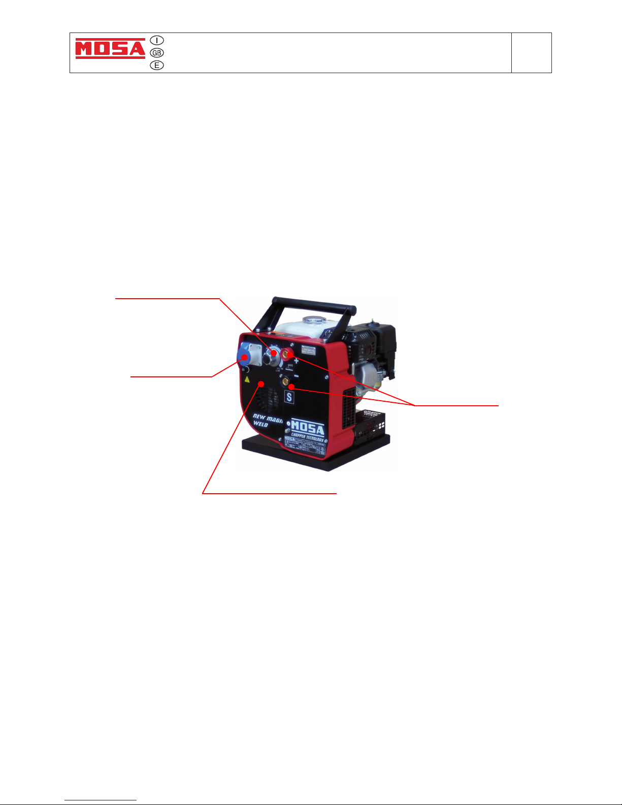
The Engine Driven Welder is a block with an engine, an aluminium casting and a front panel. Inside the
c
asting there are all electrical components of the machine: a permanent magnet alternator, a high
frequency chopper diode bridge, an electronic control board and an electromagnet.
Main features:
• D.C. welding current 150A @ 60%
• Continuous regulation of the welding current with "Chopper Technology"
• Suitable for basic and rutile electrodes. A reactance for cellulose electrodes is available as an option
• Antistick function (small arc force)
• Continuous auxiliary output 1600 W/ 230 Vdc (max. power 2000 W)
• Auto idle function
• Weight 34 Kg.
Electrical components of the machine:
• Permanent magnet alternator: the alternator has 2 galvanically separated windings, one for welding
and the other for the auxiliary output.
• Auto idle solenoid: an electromagnet inside the aluminium casting is supplied at no load only and
forces the engine speed at minimum (2000 rpm). When the load is present, welding or auxiliary
output, the electromagnet is not supplied any more and the engine speed goes to the maximum
(4000 rpm rated open circuit).
• High frequency chopper diode bridge: it regulates the welding current using the “Chopper Technology”, which chops the welding D.C. current at high frequency.
• Hall sensor: it measures with high precision the welding current and it’s completely isolated from
the welding circuit.
• Reactance for cellulose electrodes (optional).
• PWM control board: this single board controls the welding process, the auxiliary current and the elec-
tromagnet for the engine accelerator. Three integrated circuits PWM type (Pulse Width Modulation)
have been used. The use of these PWM’s not only for the welding control but also for the supply
control of the electromagnet reduces to the minimum the wasted power on the electromagnet.
• D.C. chopped auxiliary output: the auxiliary output is chopped every 50 msec. in order to prevent
damages to switches of hand tools due to arcing. This special D.C. auxiliary is suitable not only for
universal hand tools with brushes, but also for those with electronic speed control. In this case the
limit is that these tools can run at the maximum speed only, without possibility of speed regulation.
Auxiliary output
Fuse for auxiliary output
Welding sockets
Regulation knob for
welding current
NEW MAGIC WELD
Page 4

Page 5

Quality system
M
01
REV.4-03/12
UNI EN ISO 9001 : 2008
10/10/02 M01-GB
MOSA has certied its quality system according
to UNI EN ISO 9001:2008 to ensure a constant,
highquality of its products. This certication covers
thedesign, production and servicing of engine drivenwelders and generating sets.
The certifying institute, ICIM, which is a member
ofthe International Certication Network IQNet,
awarded the ofcial approval to MOSA after anexamination of its operations at the head ofce
andplant in Cusago (MI), Italy.
This certication is not a point of arrival but a
pledgeon the part of the entire company to maintain
a levelof quality of both its products and services
whichwill continue to satisfy the needs of its clients,
aswell as to improve the transparency and thecommunications regarding all the company’s activesin
accordance with the ofcial procedures and inharmony with the MOSA Manual of Quality.
The advantages for MOSA clients are:
·Constant quality of products and services at thehigh
level which the client expects;
· Continuous efforts to improve the products andtheir
performance at competitive conditions;
· Competent support in the solution of problems;
· Information and training in the correct applicationand use of the products to assure the security
ofthe operator and protect the environment;
· Regular inspections by ICIM to conrm that therequirements of the company’s quality systemand
ISO 9001 are being respected.
All these advantages are guaranteed by the CERTIFICATE OF QUALITY SYSTEM No.0192 issued
by ICIM S.p.A. - Milano (Italy ) - www.icim.it
Page 6

INDEX NEW MAGIC WELD
M
1
© MOSA REV.0 - 11/08
18/11/08 22262-GB
M 01 QUALITY SYSTEM
M 1.01 COPYRIGHT
M 1.1 NOTES
M 1.4 CE MARK
M 2 ADVICE
M 2.1 SYMBOLS
M 2.2 ADVICE ENGINE DRIVEN WELDER
M 2.3 SYMBOLS - ABBREVIATIONS LEGEND
M 2.6 INSTALLATION AND ADVICE
M 2.7 INSTALLATION
M 3 UNPACKING AND TRANSPORT
M 25 SET-UP FOR OPERATION
M 26 ENGINE STARTING
M 27 STOPPING THE ENGINE
M 31 CONTROLS
M 34... USE AS A WELDER
M 37 USE AS A GENERATOR
M 40.2... TROUBLE-SHOOTING
M 43 MAINTENANCE
M 45 STORAGE - CUST OFF
M 51 TECHNICAL DATA
M 55 RECOMMENDED ELECTRODES
M 53 DIMENSIONS
M 60 ELECTRICAL SYSTEM LEGENDE
M 61-….. ELECTRICAL SYSTEM
R1 SPARE PARTS LIST
AG... SPARE PARTS
R1.1 REQUEST FOR ORDER SPARE PARTS
Page 7
Copyright GE_, MS_, TS_, EAS
M
1.01
© MOSA 1.0-10/02
ATTENTION
© All rights are reserved to said Company.
It is a property logo of MOSA division of B.C.S.
S.p.A. All other possible logos contained in the
documentation are registered by the respective
owners.
➠
The reproduction and total or partial use, in any
form and/or with any means, of the
documentation is allowed to nobody without a
written permission by MOSA division of B.C.S.
S.p.A.
To this aim is reminded the protection of the author’s
right and the rights connected to the creation and
design for communication, as provided by the laws
in force in the matter.
In no case MOSA division of B.C.S. S.p.A. will be
held responsible for any damaga, direct or indirect,
in relation with the use of the given information.
MOSA division of B.C.S. S.p.A. does not take any
responsibility about the shown information on firms
or individuals, but keeps the right to refuse services
or information publication which it judges discutible,
unright or illegal.
10/10/02 M1-01-GB
This use and maintenance manual is an important
part of the machines in question.
The assistance and maintenance personel must
keep said manual at disposal, as well as that for
the engine and alternator (if the machine is
synchronous) and all other documentation about the
machine.
We advise you to pay attention to the pages
concerning the security (see page M1.1).
Page 8

INFORMATION
Dear Customer,
We wish to thank you for having bought from
MOSA a high quality set.
Our sections for Technical Service and Spare
Parts will work at best to help you if it were
necessary.
To this purpose we advise you, for all control and
overhaul operations, to turn to the nearest
authorized Service Centre, where you will obtain
a prompt and specialized intervention.
☞
In case you do not profit on these Services and
some parts are replaced, please ask and be
sure that are used exclusively original MOSA
parts; this to guarantee that the performances
and the initial safety prescribed by the norms in
force are re-established.
☞
The use of non original spare parts will cancel
immediately any guarantee and Technical Ser-
vice obligation from MOSA.
NOTES ABOUT THE MANUAL
Before actioning the machine please read this
manual attentively. Follow the instructions
contained in it, in this way you will avoid
inconveniences due to negligence, mistakes or
incorrect maintenance. The manual is for qualified
personnel, who knows the rules: about safety and
health, installation and use of sets movable as
well as fixed.
You must remember that, in case you have
difficulties for use or installation or others, our
Technical Service is always at your disposal for
explanations or interventions.
The manual for Use Maintenance and Spare Parts
is an integrant part of the product. It must be kept
with care during all the life of the product.
In case the machine and/or the set should be
yielded to another user, this manual must also
given to him.
Do not damage it, do not take parts away, do not
tear pages and keep it in places protected from
dampness and heat.
You must take into account that some figures
contained in it want only to identify the described
parts and therefore might not correspond to the
machine in your possession.
INFORMATION OF GENERAL TYPE
In the envelope given together with the machine
and/or set you will find: the manual for Use
Maintenance and Spare Parts, the manual for
use of the engine and the tools (if included in the
equipment), the guarantee (in the countries where
it is prescribed by law).
Our products have been designed for the use of
generation for welding, electric and hydraulic
system; ANY OTHER DIFFERENT USE NOT
INCLUDED IN THE ONE INDICATED, relieves
MOSA from the risks which could happen or,
anyway, from that which was agreed when selling
the machine; MOSA excludes any responsibility
for damages to the machine, to the things or to
persons in this case.
Our products are made in conformity with the
safety norms in force, for which it is advisable to
use all these devices or information so that the
use does not bring damage to persons or things.
While working it is advisable to keep to the
personal safety norms in force in the countries to
which the product is destined (clothing, work tools,
etc.).
Do not modify for any motive parts of the machine
(fastenings, holes, electric or mechanical devices,
others..) if not duly authorized in writing by MOSA:
the responsibility coming from any potential
intervention will fall on the executioner as in fact
he becomes maker of the machine.
Notes GE_, MS_, TS_, EAS_
M
1-1
© MOSA 1.0-10/02
☞
Notice: this manual does not engage MOSA,
who keeps the faculty, apart the essential
characteristics of the model here described and
illustrated, to bring betterments and modifications
to parts and accessories, without putting this
manual uptodate immediately.
10/10/02 M 1-1 GB
Page 9
CE MARK
M
1.4
© MOSA REV.4-10/07
10/10/02 M1-4 GB
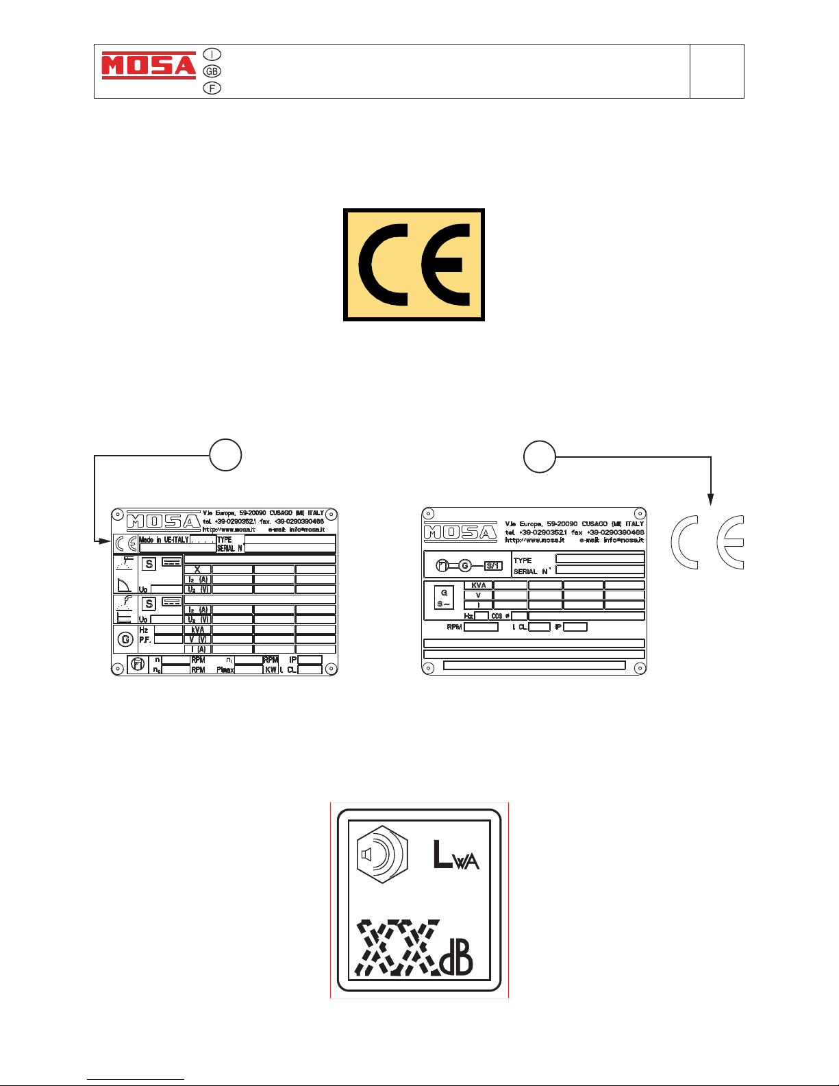
Any of our product is labelled with CE marking attesting its conformity to appliable directives
and also the fulfillment of safety requirements of the product itself; the list of these directives is
part of the declaration of conformity included in any machine standard equipment.
Here below the adopted symbol:
CE marking is clearly readable and unerasable and it can be either part of the data-plate (A) or
placed as a sticker near the data-plate (B)
A
B
Furthermore, on each model it is shown the noise level value; the symbol used is the following:
The indication is shown in a clear, readable and indeleble way on a sticker.
Page 10

18/11/08 22262-GB
Technical data
M
1.5
© MOSA REV.0 - 11/08
Technical data NEW MAGIC WELD
D.C. WELDING
Current range, continuous 30 - 150A
Open circuit voltage 40-65V
Duty cycle 150 A - 60%
D.C. GENERATION
Single-phase output (max) 2 kW / 230 V / 8.7 A
Single-phase output (continuous) 1.6 kW / 230 V / 6.9 A
Single-phase output (max) (optional) 1.5 kW / 110 V / 13.6 A
Single-phase output (continuous) (optional) 1.2 kW / 110 V / 10.9 A
ALTERNATOR Self-excited, self-regulated, brushless
Type permanent magnet, three-phase
Insulating class H
ENGINE
Mark / Model HONDA / GX 200
Type / Cooling system Gasoline 4-stroke / Air
Cylinders / Displacement 1 / 196 cm
3
Output max 5 kW (6.8 HP)
Speed 4000 rpm
Fuel consumption 313 g/kWh
Engine oil capacity 0.6 l
Starter recoil
GENERAL SPECIFICATIONS
Tank capacity 3.6 l
Running time (at duty cycle 60%) 3.5 h
Protection IP 23
Dimensions max. on base Lxlxh * 430x375x470
Weight (dry) * 34 Kg
Noise level 99 LWA (74 dB (A) - 7 m)
* Dimensions and weight are inclusive of all parts.
NEW MAGIC WELD
POWER
Declared power according to ISO 3046-1 (temperature 25°C, 30% relative hummidity, altitude 100 m above sea level).
It’s admitted overload of 10% each hour every 12 h.
In an approximative way one reduces: of 1% every 100 m altitude and of 2.5% for every 5°C above 25°C.
ACOUSTIC POWER LEVEL
ATTENTION: The concrete risk due to the machine depends on the conditions in which it is used. Therefore, it is up to the end-
user and under his direct responsibility to make a correct evaluation of the same risk and to adopt specific precautions (for
instance, adopting a I.P.D. -Individual Protection Device)
Acoustic Noise Level
(LWA)
- Measure Unit dB(A): it stands for acoustic noise released in a certain delay of time. This is not
submitted to the distance of measurement.
Acoustic Pressure (Lp) - Measure Unit dB(A): it measures the pressure originated by sound waves emission. Its value
changes in proportion to the distance of measurement.
The here below table shows examples of acoustic pressure (Lp) at different distances from a machine with Acoustic Noise
Level
(LWA)
of 95 dB(A)
Lp a 1 meter = 95 dB(A) - 8 dB(A) = 87 dB(A) Lp a 7 meters = 95 dB(A) - 25 dB(A) = 70 dB(A)
Lp a 4 meters = 95 dB(A) - 20 dB(A) = 75 dB(A) Lp a 10 meters = 95 dB(A) - 28 dB(A) = 67 dB(A)
PLEASE NOTE: the symbol when with acoustic noise values, indicates that the device respects noise emission limits
according to 2000/14/CE directive.
2000/ 14 / CE
Page 11
ADVICE NEW MAGIC WELD
MAGIC WELD 200
M
2
© MOSA REV.0 - 11/08
18/11/08 22262-GB
ATTENTION
NOTE
IMPORTANT
CAUTION
WARNING
DANGEROUS
☞ FIRST AID. In case the operator shold be sprayed by accident, from corrosive liquids a/o hot toxic gas
or whatever event which may cause serious injuries or death, predispose the rst aid in accordance
with the ruling labour accident standards or of local instructions.
☞ FIRE PREVENTION. In case the working zone,for whatsoever cause goes on re with ames liable to
cause severe wounds or death, follow the rst aid as described by the ruling norms or local ones.
This heading warns of an immediate danger for persons
as well for things. Not following the advice can result in
serious injury or death.
This heading warns of situations which could result in
injury for persons or damage to things.
To this advice can appear a danger for persons as well
as for things, for which can appear situations bringing
material damage to things.
The installation and the general advice concerning the operations, are nalized to the correct use of the machine, in the place where it is used as generator group and/or welder.
!
- Advice to the User about the safety:
N.B.: The information contained in the manual can be changed without notice.
Potential damages caused in relation to the use of these instructions will not be considered because these are
only indicative.
Remember that the non observance of the indications reported by us might cause damage to persons or things.
It is understood, that local dispositions and/or laws must be respected.
Skin contact
Eyes contact
Ingestion
Suction of liquids
from lungs
Inhalation
Wash with water and soap
Irrigate with plenty of water, if the irritation persists contact a specialist
Do not induce vomit as to avoid the intake of vomit into the lungs, send for a doctor
If you suppose that vomit has entered the lungs (as in case of spontaneous vomit) take
the subject to the hospital with the utmost urgency
In case of exposure to high concentration of vapours take immediately to a non polluted
zone the person involved
Appropriated
Not to be used
Other indications
Particular protection
Useful warnings
EXTINCTION MEANS
Carbonate anhydride (or carbon dioxyde) powder, foam, nebulized water
Avoid the use of water jets
Cover eventual shedding not on re with foam or sand, use water jets to cool off the
surfaces close to the re
Wear an autorespiratory mask when heavy smoke is present
Avoid, by appropriate means to have oil sprays over metallic hot surfaces or over
electric contacts (switches,plugs,etc.). In case of oil sprinkling from pressure circuits,
keep in mind that the inamability point is very low.
!!!
!
!
!
These headings refer to information which will assis you
in the correct use of the machine and/or accessories.
Page 12
SYMBOLS NEW MAGIC WELD
MAGIC WELD 200
M
2.1
© MOSA REV.0 - 11/08
18/11/08 22262-GB
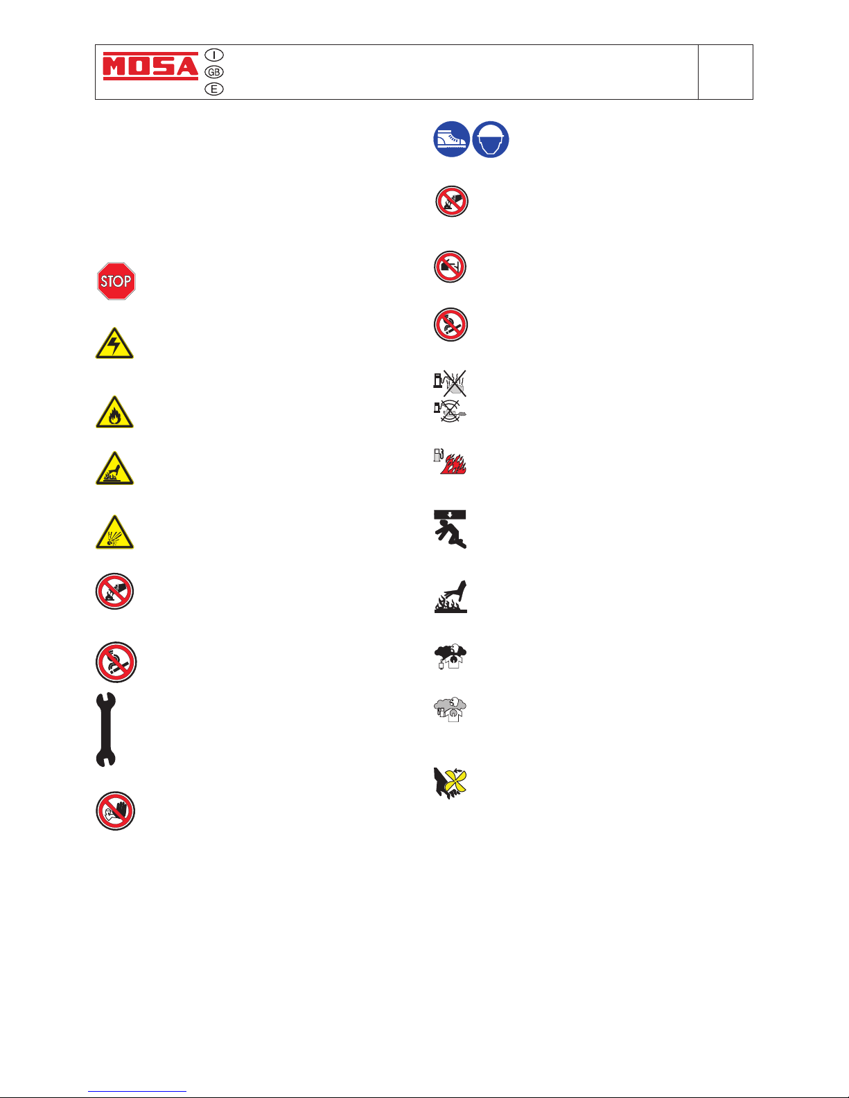
STOP - Read absolutely and be duly attentive
HIGH VOLTAGE - Attention High Voltage.
There can be parts in voltage, dangerous
to touch. The non observance of the advice
implies life danger.
FIRE - Danger of ame or re. If the advice is
not respected res can happen.
HEAT - Hot surfaces. If the advice is not
respected burns or damage to things can be
caused.
EXPLOSION - Explosive material or danger
of explosion. in general. If the advice is not
respected there can be explosions.
WATER - Danger of shortcircuit. If the advice
is not respected res or damage to persons
can be caused.
SMOKING - The cigarette can cause re or
explosion. If the advice is not respected res
or explosions can be caused.
WRENCH - Use of the tools. If the advice is
not respected damage can be caused to things
and even to persons.
ACCES FORBIDDEN to non authorizad peaple.
SYMBOLS IN THIS MANUAL
- The symbols used in this manual are designed to call
your attention to important aspects of the operation of
the machine as well as potential hazards and dangers
for persons and things.
This symbol is used to draw your attention to the fact
that the welder is being used correctly and that the
machine or equipment used operates perfectly.
Use only with safety clothing -
It is compulsory to use the personal protection means given in equipment.
Use with safe materials only -
Never use water to put out res on electrical
equipment
Use only with non inserted voltage -
It is prohibited to make interventions before
having disinserted the voltage.
No smoking -
It is prohibited to smoke while lling the tank
with fuel.
Do not refuel -
Do not refuel when the engine is hot.
Switch off the engine prior to refuelling.
Fire -
Fuel can cause res.
Use only with safety protections -
It is advisable to use all protections while
shifting the machine.
Use only with safety protections -
It is advisable to use protections suitable for
the different daily checking works.and/or of
maintenance.
Exhaust gases -
Exhaust gases from the engine can kill.
Petrol vapours -
Petrol vapours cause res and can seriously
damage your health.
Moving parts -
Moving parts are dangerous. Avoid touching any
moving parts with your hands or ngers. Never
wear loose clothing which may get trapped by
moving parts.
Page 13
ADVICE ENGINE DRIVEN WELDER NEW MAGIC WELD
MAGIC WELD 200
M
2.2
© MOSA REV.0 - 11/08
18/11/08 22262-GB
ADVICE BEFORE USE
The operator of the welder is responsible for the security of the people who work with the welder and for those in
the vicinity.
The security measures must satisfy the rules and regulations for engine driven welders.
The information given below is in addition to the local security norms.
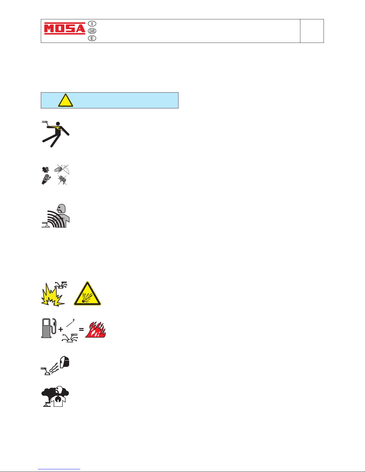
Do not touch any bare wires, leads or contacts as they may be live and there is danger of electric
shock which can cause death or serious burns. The electrode and welding cables, etc. are
live when the unit is operating.
Do not touch any electrical parts or the electrode while standing in water or with wet hands,
feet or clothes.
Insulate yourself from the work surface while welding. Use carpets or other insulating materials
to avoid physical contact with the work surface and the oor.
Do not wind cables around the body.
Always wear dry, insulating glovers, without holes, and body protection.
Estimate possible electromagnetic problems in the work area taking into account the following indications:
Telephonic wirings and/or of communication, check wirings and so on, in the immediate vicinity.
Radio and television receptors and transmettors.
Computer and other checking devices.
Critical devices for safety and/or for industrial checks.
Peapol who, for instance, use pace-maker, hearing-aid for deaf or something and else.
Devices used for rating and measuring.
The immunity of other devices in the operation area of the welder. Make sure that other used devices
are compatible. If it is the case, provide other additional measures of protection.
The daily duration of the welding time.
It is forbidden to weld in rooms containing explosive gases.
Keep amable material away from the welding area.
Do not weld on containers which contain amable material.
Do not weld near refuelling areas.
Do not weld on easily amable surfaces.
Protect face and eyes (protective mask with suitable dark lens and side screens),
ears and body (non-amable protective clothers).
☞
Avoid inhaling fumes by providing a ventilation system or, if not possible, use an approved air breather
☞
Do not work in closed areas where there is no fresh air ow.
☞
Do not use the welder to defrost (thaw) pipes.
☞
Use ear protections if the noise level is high.
DANGEROUS
Arc welders can be dangerous. Protect yourself and others
from any possible risks which may cause death or serious
injury.
!
Page 14
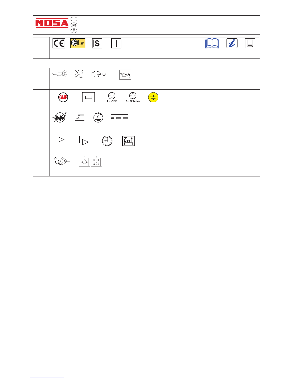
SYMBOLS - ABBREVIATIONS LEGEND
NEW MAGIC WELDM2.3
© MOSA REV.0 - 11/08
18/11/08 22262-GB
Equipment and optional
Permanent magnet
alternator
Gene ration
2000 / 14 / CE
+
-
~
°C: temperature Celsius grades
A: Ampere
B: pretrol
C.A.(c.a.): alternating current
C.C.(c.c.): direct current
cc: cm³ (volume)
CE: European norm conformity
CF: special for pipe welding
D: GFI
F: Fuse
g/kwh: grams/kilowatt hour (engine consumption)
GMP: permanent magnet alternator
Hz: frequency
I: single-phase auxiliary generation (symbol 1~)
IP: protection grads for electric devices against acess to
dangerous parts according to the IEC 529 norm (Internal
Protection)
kg: kilogram (mass)
K: welding cables set
kVA: kilovolt ampere
kW: kilowatt (engine power)
kWh: kilowatt hour (energy)
Lwa: maximum acoustic (power level) according to the
regulations in force
mm: millimeter (length) (measure)
S: symbol of EN 60974-1
T: thermic switch
V: Volt
PAR
600
Single-phase
1 ~
Engine
Welding
control
Optionals
Conformity
CE
EEC
Sound power
conformity
EN 60974-1
conformity
Various
news
Information
Users'
manual
Air
cooling
Socket
230/110/48V EEC
Welding cur-
rent electr.
regulation
Gasoline
engine
Manual
recoil
Arc
control
Fuse
Welding with
covered
electrode
Socket
230V Schuko
Ground connection point
Engine shut
down (oil)
A.C.
Plus MinusD.C.
Options on
request
Standard
equipment
Maintenance
Time
Central
lifting eye
Welding
cables
Various
Page 15

INSTALLATION AND ADVICE NEW MAGIC WELD
MAGIC WELD 200
M
2.6
© MOSA REV.0 - 11/08
18/11/08 22262-GB
INSTALLATION AND ADVICE BEFORE USE
☞ Use in open space, air swept or vent exhaust gases,
which contain the deathly carbone oxyde, far from
the work area.
POSITION
Place the machine on a level surface at a distance of at
least 1,5 m from buildings or other plants.
Check that the air gets changed completely and the hot
air sent out does not come back inside the set so as to
cause a dangerous increase of the temperature.
Make sure that the machine does not move during
the work: block it possibly with tools and/or devices
made to this purpose.
MOVES OF THE MACHINE
At any move check that the engine is off, that there
are no connections with cables which impede the
moves.
PLACE OF THE MACHINE AND/OR EQUIPMENTS
10°
10°
= 20° max
10°
10°
= 20° max
1,5 m
1,5 m
1,5 m
GAS DI SCARICO
Maximum leaning of the machine (in case of dislevel)
EXHAUST OUTPUT
ATTENTION
!
For a safer use from the operator DO NOT
t the machine in locations with high risk of
ood
Please do not use the machine in weather
conditions which are beyond IP protection
shown both in the data plate and on page
named “technical data” in this same manual.
Page 16

NEW MAGIC WELDM2.7
© MOSA REV.O-11/08
18/11/08 22262-I
Installazione
Installation
Installation
Luftzirkulation
Instalación
Page 17

UNPACKING AND TRANSPORT NEW MAGIC WELD
M
3
© MOSA REV.0 - 11/08
18/11/08 22262-GB
NOTE
Be sure that the lifting devices are: correctly mounted, ade-
quate for the weight of the machine with it’s packaging,
and conforms to local rules and regulations.
When receiving the goods make sure that the product has
not suffered damage during the transport, that there has
not been rough handling or taking away of parts contained
inside the packing or in the set.
In case you nd damages, rough handling or absence of
parts (envelopes, manuals, etc.), we advise you to inform
immediately our Technical Service.
For eliminating the packing materials, the User must
keep to the norms in force in his country.
1) Take the machine (C) out of the shipment packing.
Take out of the envelope (A) the user’s manual (B).
2) Fit the handle as shown in the instructions (tting:
screws and spanner are supplied).
3) Read: the user’s manual (B), the plates xed on the
machine, the data plate.
2
B
A
1
C
In case you should transport or move the machine, keep to the instructions as per the gures.
Be sure that the lifting devices are: correctly mounted, adequate for the weight of the machine with it’s packaging,
and conform to local rules and regulations.
Only authorized persons involved in the transport of the machine should be in the area of movement.
!
Page 18

ASSEMBLY
CTM-MW
© MOSA REV.0-06/07
M
6.11
26/06/01 M6GB
Note
: Lift the machine and assemble the parts as shown in the drawing
The CTM accessory cannot be removed from the
machine and used separately (actioned manually
or following vehicles) for the transport of loads or
anyway for used different from the machine movements.
ATTENTION
Page 19

Set-up for operation
M
25
© MOSA REV.0 - 11/08
18/11/08 22262-GB
LUBRICANT
Please refer to the motor operating manual for
the recommended viscosity.
RECOMMENDED OIL
MOSA recommends selecting AGIP engine oil.
Refer to the label on the motor for the recommended
products.
To check the oil level:
1. Remove the oil-ll tap (24) and clean the dip-stick
(23).
2. Insert the dip-stick into the oil ller without
screwing it in.
3. If the oil level is low, ll with recommended oil up
to the top of the oil ller
Oil ll tap / dip-stick
Upper oil level
MOTORS WITH OIL ALERT DEVICE
The “Oil Alert” system is designed to prevent damage to the motor due to an insufcient quantity of oil
in the cup. This system automatically shuts off the
motor before the oil level falls below the safety limit.
If the motor does not start up again after shutting
itself off, check the oil level.
FUEL
ATTENTION
!
Gasoline is highly ammable. Refuel with
motor shut off in a at surfaced well-ventilated area. Do not refuel in the presence
of ames. Avoid spilling fuel.
Any eventual spilled fuel and fumes are
ammable. Clean any dispersions of fuel
before starting up the motor.
AIR FILTER
Check that the dry air lter is correctly installed and
that there are no leaks around the lter which could
lead to inltrations of non-ltered air to the inside
of the motor.
WARNING
Do not use the machine if it is not in good
technical condition
The machine must be in good working order
before being used. Defects, especially those
which regard the safety of the machine, must
be repaired before using the machine.
Do not use without protective devices provided
Removing or disabling protective devices on the
machine is prohibited.
!
NEW MAGIC WELD
MAGIC WELD 200
Fill the tank with gasoline for automobiles (preferably lead free or with low lead content in order to
reduce deposits in the combustion chamber to a
minimum).
For further details on the type of gasoline to use,
see the motor operating manual supplied.
Do not ll the tank completely; leave a space of
approx. 10 mm between the fuel level and the wall
of the tank to allow for expansion.
Page 20

Engine starting
M
26
© MOSA REV.0 - 11/08
18/11/08 22262-GB
check daily
Do not alter the primary conditions of regulation and do not touch the sealed parts.
NOTE
!
1. Turn the fuel cock (87) to ON.
FUEL COCK
2. Switch the choke control (66) to CLOSE
N.B.: Do not use the air valve if the motor is hot
or the air temperature is too high.
CHOKE LEVER
CLOSE
CLOSE
3. Turn the engine switch (28) to the ON position
ENGINE SWITCH
STARTER GRIP
Lightly pull the start-up knob (73) until meeting
resistance, then pull decisively.
ATTENTION:
Allow the start-up knob to re-enter slowly,
avoiding having it knock against the motor and
thereby damaging the start-up system.
4. When the engine is started the machine reaches maximum engine speed immediately
(4000 rpm) for 6/7 seconds, after which the
engine speed automatically decreases to
minimum (2000 rpm). The minimum is set by
the solenoid which acts on the accelerator
lever.
5. The engine reaches maximum speed only
when current is drawn in welding or auxiliary
power mode.
NEW MAGIC WELD
MAGIC WELD 200
Page 21

Stopping the engine
© MOSA REV.0 - 11/08
18/11/08 22262-GB
Before stopping the engine it is compulsory:
- Disconnect or close any power load connected
to the system’s auxiliary generation.
- Interrupt welding.
To shut down the motor:
For shut down the motor in case of emergency,
turn the motor switch (28) to OFF.
In normal conditions, wait for the engine to reach
minimum speed automatically 6/7 seconds after
the load has been excluded. Turn the engine
in these conditions for a few minutes so that it
can cool down and then turn the engine switch
(28) to OFF.
Turn the fuel valve to the OFF position.
ENGINE SWITCH
FUEL VALVE
NEW MAGIC WELD
MAGIC WELD 200
M
27
Page 22

Comandi
Controls
Mandos© MOSA REV.O-11/08
18/11/08 22262-I
Commandes
Pos. Descrizione Description Description
9
10
12
15
22
23
24
26
27
28
31
66
73
87
F
T
Tomas de soldadura (+)
Tomas de soldadura (-)
Toma de puesta a tierra
Toma de corriente en c.c
Filtro aire motor
Aguja nivel aceite motor
Tapón llenado aceite motor
Tapón depósito
Silenciador de descarga
Mando stop
Tapón vaciado aceite motor
Pulsador Choke
Mando manual arranque
Grifo de combustible
Fisible
Regulador corr. de soldadura
Welding sockets (+)
Welding sockets (-)
Earth terminal
d.c. socket
Engine air filter
Oil level dipstick
Engine oil reservoir cap
Fuel tank cap
Muffler
Stop control
Oil drain tap
Choke button
Starting push button
Fuel cock
Fuse
Welding current regulator
Prises de soudage (+)
Prises de soudage (-)
Prise de mise à terre
Prises de courant en c.c.
Filtre air moteur
Jauge niveau huile moteur
Bouchon remplissage huile moteur
Bouchon réservoir
Silencieux d’échappement
Commande stop
Bouchon décharge huile moteur
Bouton Choke
Commande manuelle démarrage
Robinet de l'essence
Fusible
Régulateur courant soudage
Prese di saldatura (+)
Prese di saldatura (-)
Presa di messa a terra
Presa di corrente in c.c.
Filtro aria motore
Asta livello olio motore
Tappo caricamento olio motore
Tappo serbatoio
Silenziatore di scarico
Comando stop
Tappo scarico olio motore
Comando choke
Comando manuale avviamento
Rubinetto carburante
Fusibile
Regolatore corrente di saldatura
Descripción
F
M
31
F15 T 910
12
22 27 26
73
31
23-24
28
87
66
NEW MAGIC WELD
Page 23

Use as a welder
M
34
© MOSA REV.0 - 11/08
18/11/08 22262-GB
Areas for which access by non-authorized
personnel is forbidden are:
- the control panel (at the front) - the endothermic motor discharge.
WARNING
!
PUSH AND
TWIST
CONNECT WELDING CABLES
Insert the welding cable plugs completely in the
sockets, turning clockwise to lock them in place.
Connect the earth clamp to the negative pole
and the electrode holder to the positive.
Pay attention to the two polarities on the
welding circuit, which must not come into
electrical contact with each other.
- Carefully tighten the output cables to the
bushings; if loose, they can cause problems
of overheating and damage the bushings,
cables, etc.
- Make certain the grounding pincer is connected as near as possible to the work station.
ATTENTION
!
To reduce the risk of electromagnetic interference, keep the welding cable length short and
keep them on or near the ground. If possible,
welding operations should not be done near
sensitive electronic devices. If interference
continues to occur, adopt additional measures:
shift the group, use shielded cables, line lters,
shield the entire work area.
If the above solutions do not sufce, consult
our Technical Servicing Department.
ADJUSTING THE WELDING CURRENT
The welding current is regulated by turning knob
“T” continuously. If set to the minimum (turned
fully in an anticlockwise direction) it provides
a current of approximately 30 A; if set to the
maximum (turned fully in a clockwise direction)
it gives a maximum current of approximately
150A.
RECOMMENDED ELECTRODES
All the electrodes on the market can be used,
however for cellulose electrodes we recommend Magic Weld with added reactor.
NEW MAGIC WELD
Page 24

Use as a welder
© MOSA REV.0 - 11/08
18/11/08 22262-GB
AUTO IDLE
Operation
When the engine is switched on it immediately
reaches a maximum speed of 4000 rpm for approximately 6/7 seconds for easy start up, after
which it automatically decreases and idles at
2000 rpm. It remains at this speed until current
is drawn when set to weld or auxiliary power.
When set to weld mode the machine reaches
maximum engine speed as soon as there is minimum contact between the tip of the electrode
and the piece to be welded and also when set to
generation drawing a minimum of 250 – 300 W
The machine returns to minimum 6/7 seconds
later if power is not drawn during welding or
generation.
Checking and adjusting idling speed
- Check idling speed when COLD;
- When the engine is switched on it reaches ma-
ximum speed; after 6/7 seconds it decreases
automatically to idle. Check the speed when
the engine idles;
- The idling speed corresponds to 33-35 Vdc
(only for Italy 42-45 Vdc) at the welding sockets
or the equivalent at 2000-2200 rpm.
Minimum welding voltage TOO LOW
- From Fig. 1 proceed as follows:
• when the machine idles (engine cold)
• Keep pin A locked (8 mm spanner) and un-
screw nut B (7 mm spanner)
• Again with pin A locked, turn nut C clockwi-
se (7 mm spanner) 1 - 3 mm: The more it is
extended the more the idle speed increases
• Tighten nut B on pin A and check the idling
speed.
Minimum welding voltage TOO HIGH
- From Fig. 1 proceed as follows:
• When the machine idles (engine cold)
• tKeep pin A locked (8 mm spanner) and un-
screw nut B 1-3 mm (7 mm spanner)
• Again with pin A locked, turn nut C anticlockwi-
se (7 mm spanner) until nut B touches pin A
• Tighten nut B against pin A and check that the
idling speed is correct.
Adjusting the maximum engine speed
FIG. 1
FIG. 2
To check that the maximum engine speed is
correct simply measure the welding voltage
(under no-load conditions) at maximum engine
speed which must be 49-51 V (only for Italy
66-68 Vdc).
Turn screw (A) to adjust the engine speed Fig. 2.
Turning the screw clockwise increases the idling
speed , screwing it anticlockwise decreases the
maximum engine speed.
M
34.1
NEW MAGIC WELD
Page 25

Checking and adjusting the maximum welding current
© MOSA REV.0 - 11/08
18/11/08 22262-GB
dal ponte chopper
from chopper welding bridge
dal sensore di corrente
from current sensor
taratura corrente max. di sald. (*)
welding max. current adjustment (*)
dall'alternatore
from alternator
dai ponti ausiliari
from aux. bridges
dal frontale
from frontal
dal solenoide
from solenoid
NEW MAGIC WELD
M
34.2
Sol. 1
Sol. 2
Si
Su
Ri
Ru
Y
Ti
Tu
2
1
14
13 7
8
1
2
11
12
2
1
Y
T
R
S
S
R
T
ON
OFF
*) Tutte le volte che viene sostituita o la scheda o il sensore di corrente è necessario procedere ad
una verica della massima corrente di saldatura e eventualmente procedere ad una sua taratura nel seguente modo:
- Lasciare ssato il frontale solo con la vite centrale inferiore e non stringerla in modo che il frontale nella
sua parte superiore rimanga staccato di circa 7-8 cm.
- Ruotare il trimmer sulla scheda tutto in senso antiorario.
- Porre i dip switch secondo la gura
- Vericare che al minimo del potenziometro corrisponda il minimo della manopola.
- Porre la manopola di saldatura al minimo e avviare il motore. Lasciare che la macchina vada al
minimo poi fare un corto circuito tra il + e - tramite i cavi di saldatura.
- Ruotar e la manopola di saldatura al massimo.
- Ruotare lentamente il trimmer in senso orario afnché la corrente di saldatura arrivi a 140A.
*) Every time either the board or the current sensor is changed, it is necessary to check the max. welding
current and, if it is the case, to set it as follows:
- Keep the front panel xed with its lower central screw and don't tight it, so that the front panel in its upper part can
have a gap of 7-8 cm.
- Rotate the trimmer on the board fully anticlockwise.
- Put the dip switch as drawing
- Check that to the minimum of the potentiometer corrisponds the minimum of the knob.
- Put the welding knob to the minimum and start the engine.
- Let the machine idle, then shortcircuit between the + and - welding sockets through the welding cables.
- Rotate the welding knob to the maximum.
- Slowly rotate the trimmer clockwise so that the welding current reaches 140 A.
Dip switch
Dip switch
Dip switch
Page 26

Parallel engine driven welder
M
34.3
© MOSA REV.0 - 11/08
How to put two machines in parallel:
from the front panels of the machines connect the two positives welding sockets(+) between
themselves and the two negative welding sockets bethween themselves.
To effect the connection ask for the accessory K2X150.
ATTENTION: use t cables and tight at the connection point.
How to proceed:
- start the machine putting the two welding handles (T) in the wanted position (half of the total
current);
- put in parallel with the right cables;
- proceed with welding.
18/11/08 22262-GB
NEW MAGIC WELD
Page 27

Use as a generator
© MOSA REV.0 - 11/08
18/11/08 22262-GB
WARNING
!
GENERATION IN C.C. (CONTINUOUS CURRENT WITH MICRO-INTERRUPTION)
Machines with three pin outlets for auxiliary
supply have, at each outlet, isolated active
and neutral sockets, and an earth socket. Only
the earth socket is bonded to the frame of the
machine.
For your safety, all auxiliary equipment, extension cords, appliance cords, plugs, plug sockets
and appliances should be in good condition and
correctly wired and connected. All earthing wires, qhere used, must be continuous. Extension
corde with three wires should be used except
for double insulated appliances.
The frame of the unit should not be connected to the general mass of earth by an earth
spike or by any other means, but should be
isolated from earth.
Note: in line with current practice, a oating
auxiliary power system is used. The auxiliary
power windings are not connected to the frame, hence a "residual current device" is not
required.
- If the generator is used to feed more complex
circuits, or used in special environments, for
example: building sites, it is obligatory to
interpose between the socket and the loads a
small distribution panel complete with electrical
safeties foreseen by regulatory norms in force
in matters of electrical installation.
It is absolutely forbidden to connect the
unit to the public mains and/or another
electrical power source.
Areas for which access by non-authorized
personnel is forbidden are:
- the control panel (at the front) - the endothermic motor discharge.
M
37
NEW MAGIC WELD
Page 28

Trouble-shooting
© MOSA REV.0 - 11/08
18/11/08 22262-GB
The motor does not start up,
or starts up and then stops
immediately
1) Engine switch (28) at position
OFF
2) Lack of or insufcient oil in the
motor
3) Faulty motor stopping device
(oil-alert)
4) Lack of fuel in tank or fuel tap
closed
5) Dirty or faulty spark plug
6) Cold motor
7) Other causes
1) Position switch to ON
2) Rell or top off
3) Replace
4) Rell the tank. Open the fuel tap
5) Clean or check and eventually
replace
6) Hold down the CHOKE button,
after start-up, for a longer period
of time
7) Consult the motor Operating Manual.
Problem Possible cause Solution
No current under no-load
conditions in weld mode
No current under no-load
conditions in auxiliary power
mode
Incorrect minimum voltage
1) Use a multimeter to test that there
are 3 Kohms between pins 1-2; if
NOT replace the bridge
2) Replace
3) Disconnect the welding and
auxiliary power cables. Use a
voltmeter to check that there is
48 Vac at the outputs in weld and
approximately 170 Vac in the 230
V version and 90 Vac in the 110
V version. Carry out the check
when the engine idles (disconnect one of the two wires to the
solenoid)
1) Chopper welding bridge broken
2) Faulty circuit
3) Faulty alternator
1) replace the fuse
10A retarded for version 230V
15A retarded for version 110V
2) Use a multimeter to check the 2
single phase diode bridges on the
auxiliary power
3) Replace
4) Disconnect the welding and
auxiliary power cables. Use a
voltmeter to check that there is
48 Vac at the outputs in weld and
approximately 170 Vac in the 230
V version and 90 Vac in the 110
V version. Carry out the check
when the engine idles (disconnect one of the two wires to the
solenoid).
1) Fuse open
2) Auxiliary power diode bridge
broken
3) Faulty circuit
4) Faulty alternator
under no-load conditions 1) Adjust the solenoid as shown on
page M34.
1) Incorrect solenoid adjustment
M
40.2
NEW MAGIC WELD
Page 29

Trouble-shooting
© MOSA REV.0 - 11/08
18/11/08 22262-GB
M
40.2.
1
Problem Possible cause Solution
RESISTENCE OF WINDING AT 20°C
Ω (ohm)
NOTE
Output in weld mode
Between green / black cable
Between green / red cable
Between black / red cable
0,030
0,030
0,030
All cables of the same colour are
connected in parallel
Auxiliary power outputs 230 Vdc
Between the black cables: R / S
Between the black cables: R / T
Between the black cables: S / T
1,2
1,2
1,2
Auxiliary power outputs 110Vdc
Between the black cables: R / S
Between the black cables: R / T
Between the black cables: S / T
1,0
1,0
1,0
Cable Y is connected to the centro
stella of the three phase circuit
Cable Y is connected to cable T
1) Adjust the maximum engine speed as shown on page M34.
Incorrect maximum voltage
under no-load conditions
Engine always at idle speed
1) Replace
Engine always at maximum
speed
1) Incorrect maximum engine
speed
1) Faulty circuit
1) Replace;
2) Check that the resistance of the
solenoid winding is approximately
10 ohm.
Insufficient power during
welding or generation
1) Dirty petrol lter,
dirty air lter,
dirty carburetor.
See engine instruction booklet.
1) Disconnect all the outputs; 3 for
1) faulty circuit
2) Faulty solenoid
1) Engine
1) a lt er na to r w in di ng s n o t
Irregular or inconsistent welding current
insulated from earth
2) welding chopper bridge not
insulated from earth
3) power cables not insulated
from earth
4) faulty circuit
welding which go to the chopper
bridge and 4 for auxiliary power
which go to the circuit board.
Use a multimeter to check the
insulation of the alternator;
2) disconnect the 3 welding cables,
the + and - for welding, the black
wire and the connector which
go to the circuit board, Use a
multimeter to check that the
bridge is insulated from the earth.
3) check that the cables inside the
aluminium casting, are properly
insulated;
4) Replace
NEW MAGIC WELD
Page 30

MAINTENANCE
© MOSA REV.0 - 11/08
18/11/08 22262-GB
!
!
• Maintenance and repair work should only be done by qualied personnel.
• Stop the engine before doing any work on the machine. If
for any reason the machine must be operated while working
on it, be careful not to touch rotating parts, hot surfaces,
live wires, etc. which may be unprotected.
• Remove protective guards only when necessary to perform
maintenance and replace them immediately after the maintenance is completed.
• Use suitable tools and wear suitable clothes.
• Do not modify the machine without prior authorization
ATTENTION
When carrying out maintenance operations
be careful to avoid polluting the environment
with the materials used during maintenance.
Follow all local health and safety regulations.
IMPORTANT
MAINTENANCE OF THE MACHINE
Maintenance refers to all operations regarding
the control and replacement of mechanical and
electrical parts subject to wear. In addition it
refers to the control and topping up or replacement of uids such as fuel, oil and the regular
cleaning of the machine.
Repairs refers to the substitution of worn or
damaged parts and repairs should be carried
out by Authorized Service Centres.
Refer to the Engine Manufacturer’s Manual for
the maintenance instructions for the engine.
Periodic maintenance should be performed
according to the schedule shown in this manual.
On a regular basis check that there are no
obstructions in the aspiration/exhaust ducts of
the alternator, the engine or the housing which
could restrict the ow of cooling air.
DRY AIR FILTER
Replace the air lter cartridge every 200 hours
under normal conditions and every 100 hours
in dusty environments.
PERMANENT MAGNET ALTERNATOR
No maintenance is necessary, as the alternator
has no brushes or slip rings, and there are no
devices for regulation of the output.
WARNING LABELS AND DECALS
Check warning labels and decals once a year
and replaced if missing or unreadable.
CABLES AND CONNECTIONS
Periodically check the condition of the cables
and tighten the connections.
HOT surface
can
hurt you
MOVING
PARTS
can injure
M
43
NEW MAGIC WELD
MAGIC WELD 200
Page 31

STORAGE - CUST OFF
© MOSA REV.0 - 11/08
18/11/08 22262-GB
M
45
Have qualied personnel prepare the ma-
chine for the cust-off.
STORAGE
In case the machine will not be used for more
than 30 days, it should be stored in a suitable
area where it is protected from the elements to
prevent rusting, corrosion and other damage to
the machine.
ENGINE
Run the engine until it stops from lack of fuel.
For long periods of storage, refer to the engine
manufacturer’s manual.
Clean the machine carefully.
Cover the machine with a plastic cover and store
in a dry place.
CUST-OFF
As cust off we intend all operations to be made,
at utilizer’s care, at the end of the use of the
machine.
This comprises the dismantling of the machine,
the subdivision of the several components for
a further reutilization or for getting rid of them,
the eventual packing and transportation of the
eliminated parts up to their delivery to the store,
or to the bureau encharged to the cust off or to
the storage ofce, etc.
The several operations concerning the cust off,
involve the manipulation of uids potentially
dangerous such as: lubricating oil.
The dismantling of metallic parts liable to cause injuries or wounds, must be made wearing
heavy gloves and using suitable tools.
The getting rid of the various components of the
machine must be made accordingly to rules in
force of law a/o local rules.
Particular attention must be paid when
getting rid of: lubricating oils, inamable
liquids such as fuel.
The machine user is responsible for the observance of the norms concerning the environment
conditions with regard to the elimination of the
machine being cust off and of all its components.
In case the machine should be cust off without
any previous disassembly it is however compulsory to remove:
- tank fuel
- engine lubricating oil
NOTE: MOSA is involved with custing off the
machine only for the second hand ones, when
not reparable.
This, of course, after authorization.
In case of necessity for rst aid and re prevention, see page M2.
In the storage or cust-off operations avoid
that polluting substances, liquids, exhausted
oils, etc. bring damage to people
or things or can cause negative
effects to surroindings, health or
safety respecting completely the laws and/or
dispositions in force in the place.
!
IMPORTANT
NEW MAGIC WELD
MAGIC WELD 200
Page 32

RECOMMENDED ELECTRODES (In accordance with A.W.S Standard)
MS_, TS_
M
55
© MOSA 1.0-10/03
The information here below are to be intended only as indicative since the above norm is much larger.
For further details please see the specific norms and/or the manufacturers of the product to be used in the welding
process.
RUTILE ELECTRODES: E 6013
Easily removable fluid slag, suitable foe welding in all position.
Rutile electrodes weld in d.c. with both polarities (electrode holder at + or -) and in a.c..
Suitable for soft steels R-38/45 kg/mm2 . Also for soft steels of lower quality.
BASIC ELECTRODES: E 7015
Basic electrrodes wels onlu in d.c. with inverse polarity (+ on the electrode holder) ; there are also types for a.c.
Suitable for impure carbon steels. Weld in all position.
HIGH YIELD BASIC ELECTRODES: E 7018
The iron contained in the coating increases the quality of metal added. Good mechanical properties. Weld in all position.
Electrode holder at + (inverse polarity). Wld deposit of nice aspect, also vertical. Workable; high yield.
Suitable for steels with high contens of sulphur (impurities).
CELLULOSIC ELECTRODES: E 6010
Cellulosic electrodes weld only in d.c. with polarity + electrode holder - ground clamp.
Special for steels run on pipes with R max 55 kg/mm2. Weld in all position. volatile slag.
ELECTRODES IDENTIFICATION ACCORDING TO A.W.S. STANDARDS
EX XY Z
2 digits: type of coating
and electric power
conditions.
(see table 3)
1 digits: welding
positions.
(see table 2)
2÷3 digits: tesile strenght of
the weld deposit.
(see table 1)
symbol for
"Coated
electrode"
10 Cellulose electrodes for d.c.
11 Cellulose electrodes for a.c.
12 Rutile electrode for d.c.
13 Rutile electrode for a.c.
14 High yield rutile electrodes
15 Basic electrodes for d.c.
16 Basic electrodes for c.a.
18 High yield basic electrodes for d.c.
(inverse polarity)
20 Acid electrodes for flat or front position welding for
d.c. (- pole) and for a.c.
24 High yield rutile electrodes for flat or front plane
position welding for d.c. and a.c.
27 High yield acid electrodes for flat or front plane
position welding for d.c. (- pole) and a.c..
28 High yield basic electrodes for flat or front plane
position welding for d.c. (inverse polarity)
30 Extra high yield acid electrodes, extra high
penetration if required, for flat position welding only
for d.c. (- pole) and a.c.
N° Descrizione
Number
Strenght
K.s.l. Kg/mm
2
60
70
80
90
100
110
120
60.000
70.000
80.000
90.000
100.000
110.000
120.000
42
49
56
63
70
77
84
for all positions
for plane and verticl
for plane posotion only
1
2
3
Table 1
Table 2 Table 3
10/10/03 M55GB
Page 33

© MOSA REV.O-11/08
18/11/08 22262-I
M
53
Dimensioni
Dimensions
Dimensions
Abmessungen
Dimensiones
375
430
470
510
854
610
402
~
566
NEW MAGIC WELD
Page 34

18/11/08 22262-I
NEW MAGIC WELD
M
60
© MOSA REV.O-11/08
A : Alternatore
F : Fusibile
H : Presa 230V monofase
I : Presa 110V monofase
R : Unità controllo saldatura
T : Regolatore corrente saldatura
Y : Ponte diodi saldatura
F1 : Elettromagnete acceleratore
S2 : Trasmettitore livello olio
F3 : Pulsante stop
G3 : Bobina accensione
H3 : Candela accensione
W6 : Sensore di hall
Legenda schema elettrico Electrical system legende Legende des schemas electriques
Stromlaufplan-Referenzliste Leyenda esquema eléctrico
A: Alternator
F: Fuse
H: 230V 1phase socket
I: 110V 1-phase socket
R: Welding control PCB
T: Welding current regulator
Y: Welding diode bridge
F1: Acceleration solenoid
S2: Oil level transmitter
F3: Stop push-button
G3: Ignition coil
H3: Spark plug
W6: Hall sensor
A : Alternateur
F : Fusible
H : Prise 230V monophasé
I : Prise 110V monophasé
R : Unite contrôle soudage
T : Régulateur courant de soudage
Y : Pont diodes soudage
F1 : Electro-aimant accélérateur
S2 : Transmetteur niveau huile
F3 : Bouton stop
G3 : Bobine allumage
H3 : Bougie allumage
W6: Senseur de hall
A Generator
F Sicherung
H Steckdose 230V 1-phasig
I Steckdose 110V 1-phasig
R Steuerplatine Schweißstrom
T Schweißstromregler
Y Diodenbrücke Schweißstrom
F1 Elektromagnet Motordrehzahl
S2 Ölstandssensor
F3 Taste Stopp
G3 Zündspule
H3 Zündkerze
W6 Hall-Sensor
A :Alternador
F :Fusible
H :Toma 230V monofásica
I :Toma 110V monofásica
R :Unidad control soldadura
T :Regulador corriente soldadura
Y :Puente diodos soldadura
F1 :Electromagnetismo acelerador
S2 :Captador nivel aceite
F3 :Pulsador stop
G3 :Bobina encendido
H3 :Bujía encendido
W6 :Sensor de entrada
Page 35

18/11/08 22262-I
Schema elettrico
Electric diagram
Esquema eléctrico
NEW MAGIC WELD
(110V version)
M
61
© MOSA REV.O-11/08
20090-CUSAGO (MI)-ITALY
http://www.mosa.it
MAGIC WELD
Wiring Diagram 22263.prg
22240.S.060-F
Leporace N.
2
Approvato:
Esp.
Data Dis. Appr.
Modifica
Denominazione:
Macchina:
Data:
Progetto:
di n°
Pag.n°
2
Date Appr.
Approved:
Project:
Denomination:
Machine:
Modification
Date:
Da Pag.
Alla Pag.
To Page
From Page
Designer:
of n°
Desi.
Dis. n°:
Exp.
Page n°
Dwg. n°:
Disegnatore:
La MOSA si riserva a termini di legge la proprieta' del presente disegno con divieto di riprodurlo o comunicarlo a terzi senza sua autorizzazione.
02.07.2004
-
+
KEY COLOR
LEGENDA COLORI
NERO/BLACK
(R)
ROSSO/RED
(B)
(B)
Y
T
S
R
(B)
GIALLO/YELLOW
(B)
(Y)(B)(Y)
(Y)
(B)
(Y)
(B)
(B)
(Y)
(BL)
(BL)
BLU/BLUE
(Y)
(R)
(B)
(B)
(R)
(BL)
+
-
~
~
~
-
+
Z
3~
GS
A
W6
Y
F1
S2G3H3
ONOFF
F3
P1
P3
P2
Sol. 1
Sol. 2
Si
Su
Ri
Ru
Tu
Ti
Y
1
2
3
4
5
6
7
8
9
10
11
12
R
T
A
18.04.2005 N.L.
T
(R)
(B)
S
R
+
-
+
-
F
15A
110V/16A
I
Aggiunto soppressore (Zenamic) a pr
otezione dei ponti diodi ausiliaria.
B Aggiunto ponticello tra pin9e10suc onn. P1 (opzione Arc- Force). 22.03.2006 N.L.
(BL)
N.L.
C
03.04.2006
1Kohm/¼W
Aggiunto resistenza 1Kohm/¼W nel pontic
ellotrapin9e10suconn. P1.
22Kohm/2W
D
27.06.2006 N.L.
Aggiunto resistenza 22Kohm/2W in parallelo uscita ponti diodi ausilaria.
10µH
Aggiunto induttanza 10µH su cavo
1 connettore P1. 23.05.2007 N.L.
E
Aggiunto reattore(W)F
27.10.2008 N.L.
W
Page 36

18/11/08 22262-I
Schema elettrico
Electric diagram
Esquema eléctrico
NEW MAGIC WELD
(EU Version)
M
61.1
© MOSA REV.O-11/08
20090-CUSAGO (MI)-ITALY
http://www.mosa.it
MAGIC WELD
Wiring Diagram
22243.prg
22243.S.060-C
Leporace N.
2
Approvato:
Esp.
Data
Dis.
Appr.
Modifica
Denominazione:
Macchina:
Data:
Progetto:
di n°
Pag.n°
2
Date
Appr.
Approved:
Project:
Denomination:
Machine:
Modification
Date:
Da Pag.
Alla Pag.
To Page
From Page
Designer:
of n°
Desi.
Dis. n°:
Exp.
Page n°
Dwg. n°:
Disegnatore:
La MOSA si riserva a termini di legge la proprieta' del presente disegno con divieto di riprodurlo o comunicarlo a terzi senza sua autorizzazione.
-
+
T
(R)
(B)
KEY COLOR
LEGENDA COLORI
NERO/BLACK
(R)
ROSSO/RED
(B)
(B)
Y
T
S
R
S
R
(B)
GIALLO/YELLOW
(B)
(Y)(B)(Y)
(Y)
(B)
(Y)
(B)
(B)
(Y)
(BL)
(BL)
BLU/BLUE
(BL)
(Y)
(R)
(B)
(B)
(R)
-
+
Z
3~
GS
A
W
+
-
+
-
F
10A
230V/16A
H
W6
Y
F1
S2G3H3
ONOFF
F3
P1
P3
P2
Sol. 1
Sol. 2
Si
Su
Ri
Ru
Tu
Ti
Y
1
2
3
4
5
6
7
8
9
10
11
12
R
A
18.04.2005 N.L.
Aggiunto soppressore (Zenamic) a protezione dei ponti diodi ausiliaria.
02.07.2004
2x15Kohm/2W
N.L.
B Aggiunto n° 2 resistenze da 15Kohm/2W in parallelo uscita ponti diodi ausilaria.
19.09.2006
10µH
C Aggiunto induttanza 10µH su cavo 1 connettore P1.
23.05.2007 N.L.
Page 37

SPARE PARTS LIST
R
1
© MOSA 1.0-03/00
MOSA guarantees that any request for spare parts will be satised.
To keep the machine in full working order, when replacement of MOSA spare parts is required, always
ask for genuine parts only.
When ordering the spare parts, it is recommended to indicate:
1) Y serial number
2) Y model of welder and/or generating set
3) u n. table
4) u n. position
5) quantity
14/12/986Q16M31
TAVOLA RICAMBI - SPARE PARTS - PIECES DE RECHANGE - ERSATZTEILE
ON
OFF
START
*
VE
NULLEITERAUFMASSE
NULVERBONDENMETMASSA
NEUTROCONECTADOAMASA
NEUTRERACCORDEAUBATI
NEUTRALBONDEDTOFRAME
NEUTROCOLLEGATOAMASSA
*
65
60
Hz A
10
50
15
55
500
300
V
ST
RS
0
200
100
TR
0
h
HOURMETER
I
0
EA
1
25
20
125
1-3 13
18
17 16
20-21-22
12
21-22-23
14
11
8
2
19
15
4-5-6
EA
1
12
50 Hz
50 Hz
3
EA
1
4
12
TS 0000 GE
V.le Europa,59 - 20090 CUSAGO (MI) ITALY
Tel. +39-02 90352.1 - fax +39-02 90390466
0987654321
TYPE
SERIAL N°
22/03/00 R1GB
The requested data are to be found on the data
plate located on the machine structure, quite visible
and easy to consult.
Y
ABBREVIATIONS AND SYMBOLS:
(EV) Whenordering,specifytheenginetypeand
theauxiliaryvoltage
(ER) Enginewithrecoilstarteronly
(ES) Enginewithelectricstarteronly
(VE) E.A.Sversiononly.
(QM) Whenordering,specifythelengthinmeters
(VS) Specialversiononly
(SR) Byrequestonly
Page 38

18/11/08 22262-I
© MOSA REV.O-11/08
Ricambi
Spare parts
Piéces de rechange
Ersatzteile
Tabla de recambios
AG
NEW MAGIC WELD 5
1
2
(230V Version)
(110V Version)
3
3a
4
6
5
5a
(110V version)
(230V version)
7
8
9
10
11
12
13
14
15
16
17
18
20
23
24
22
19
21
25
Page 39

18/11/08 22262-I
© MOSA REV.O-11/08
NEW MAGIC WELD
AG
5.1
Ricambi
Spare parts
Piéces de rechange
Ersatzteile
Tabla de recambios
Pos. Rev. Cod. Descr. Note
1 222406020 VENTOLA CENTRIFUGA / FAN
2 222403047 ASSIEME MOZZO/ROTORE /HUB / SHAFT ASSY
3 222413025 STATORE AVVOLTO 230 VAC / STATOR 230V Versione 230V /230V version
3a 222403025 STATORE AVVOLTO 110 VAC / STATOR 110V Versione 110V / 110V version
4 222418263 PIASTRINA FERMA CAVI
5 1270040 PONTE DIODI / DIODE BRIDGE 35A800V Versione 110V / 110V version
5a 1270070 PONTE DIODI / DIODE BRIDGE Versione 230V / 230V version
6 222422200 MOTORE HONDA GX200T - EPA / HONDA ENGINE GX200T
7 102011270 TAPPO MANIGLIA / STOPPER, HANDLE
8 222401226 MANIGLIA DI SOLLEVAMENTO / LIFTING HANDLE
9 222509800 SCHEDA SALDATURA (MAGIC WELD) / WELDING PCB
10 222405400 PONTE CHOPPER / WELDING PCB
11 222405107 SENSORE DI HALL 250A / HALL SENSOR
12 222408065 GRIGLIA USCITA ARIA / AIR OUTLET GRID
13 222403040 CARTER ATT. MOTORE/ALTERN. (LAV.) / BOX
14 222409050 ELETTROMAGNETE ECONOMIZZATORE / ECONOMIZER SOLENOID
15 222402244 MORSETTO PER FUNE COMANDO / COMMAND WIRE CLAMP
16 222409101 SUPPORTO ELETTROMAGNETE / SOLENOID BRACKET
17 222434126 LAMIERA PROTEZIONE REATTORE / REACTOR PROTECTION
18 222401035 ANTIVIBRANTE D.25x30 / VIBRATION DAMPER
19 222402038 RONDELLA DISTANZIALE / WASHER
20 222411050 BASE SUPPORTO MOTORE/ALTERN. / BASE
21 222434100 REATTORE DI LIVELLO / REACTOR
22 222402199 SQUAD.SUPP.LEVA COMAN.GAS MOT.(COMPL.) / ENGINE GAS LEVER BRACKET
23 222408460 FILO RIGIDO COMANDO ACCELER. / ACCELERATOR WIRE
24 222402230 ASSIEME LEVA COMANDO GAS MOT. / ENGINE GAS LEVER
25 208029104 COLONNETTA / SPACER
Page 40

18/11/08 22262-I
© MOSA REV.O-11/08
NEW MAGIC WELD
AG
2
Ricambi
Spare parts
Piéces de rechange
Ersatzteile
Tabla de recambios
110I Version
230I Schuko Version
15
16
230I Version
123 4* 567
8*
9*
10*
11*
12*
13*
(*) 14
FUSE
10
20
30
40
50
60
70
1a
Page 41

18/11/08 22262-I
© MOSA REV.O-11/08
NEW MAGIC WELD
AG
2.1
Ricambi
Spare parts
Piéces de rechange
Ersatzteile
Tabla de recambios
Pos. Rev. Cod. Descr. Note
1 1291180 FUSIBILE Versione 230V
1a 1291090 FUSIBILE Versione 110V
2 103011320 PORTA FUSIBILE fino a REV.2-11/05 Del. 78/06 del 18/05/06
2 873789045 PORTA FUSIBILE da REV.3-06/07 Del.78/06 del 18/05/06
3 307017240 PRESA 220V 16A
4 270009701 POTENZ. LINEARE A FILO 5Kohm (*)
5 102301310 PRESA DI SALDATURA (+)
6 102044400 PRESA DI SALDATURA (-)
7 222427020 FRONTALE
8 1018090 ANELLO OR (*)
9 107799349 BUSSOLA MANOP.POT.REG.UN.SALD. (*)
10 207409751 MANOPOLA REGOLAZ.CORR.SALDAT. (*)
11 107011870 TAPPO (*)
12 6060070 GRANO FILETTATO E.I.M4X8 (*)
13 6060050 GRANO M 4X4 UNI 5923 R45H (*)
14 222440543 KIT MANOPOLA ARCO SALD. COMPL, (* 4+8÷13)
15 307047250 PRESA 110V 16A Versione 110V
16 259107241 PRESA SCHUKO 16A 230V - 2P+T Versione Schuko
Pos. Rev. Cod. Descr. Note
1 1291180 FUSE 230V version
1a 1291090 FUSE 110V version
2 103011320 HOLDER, FUSE up to REV.2-11/05 Del. 78/06 del 18/05/06
2 873789045 HOLDER, FUSE from REV.3-06/07 Del.78/06 del 18/05/06
3 307017240 EEC SOCKET 16A, 220V 2P+T
4 270009701 POTENTIOMETER (*)
5 102301310 WELDING SOCKET (+)
6 102044400 WELDING SOCKET (-)
7 222427020 FRONT PANEL
8 1018090 O RING (*)
9 107799349 SLEEVE (*)
10 207409751 KNOB WELDING CURRENT REGULAT. (*)
11 107011870 CAP (*)
12 6060070 DOWEL (*)
13 6060050 DOWEL (*)
14 222440543 KIT FOR ARC FORCE KNOB (*4+8÷13)
15 307047250 SOCKET 110V 16A 110V version
16 259107241 SOCKET SCHUKO 16A 230V 2P+T Schuko version
Page 42

© MOSA REV.0-06/07
29/06/01 KA
CTM-MW
222420130
KA
18
1
2
3
4
5
6
7
8
9
10
Pos. Rev. Cod. Descr. Descr. Note
1 222421050 BARELLA
PROTECTIVE FRAME
2 222421226 MANIGLIA DI SOLLEVAMENTO
LIFTING HANDLE
3 219861159 MANOPOLA
KNOB
4 222422038 RONDELLA
WASHER
5 222421170 RUOTA
WHEEL
6 222421051 PIEDE DI STAZIONAMENTO
PARKING STAND
7 222421160 ASSALE
AXLE
8 6075020 COPIGLIA
PIN, SPLIT
9 222421356 PIASTRA FISS. BASAMENTO
FIXING PLATE FOR BASE
10 222429359 SPINA DI SICUREZZA
SAFETY PLUG
Page 43

Page 44

MOSA div. della BCS S.p.A.
Stabilimento di Viale Europa, 59
20090 Cusago (MI) Italia
Tel. + 39 - 0290352.1
Fax + 39 - 0290390466
 Loading...