

Page 1
1
Mortex Products, Inc. / FT. WORTH, TX 76106 G17 / G18 Installation Instructions Printed 04/04
16
Mortex Products, Inc. / FT. WORTH, TX 76106 G17 / G18 Installation Instructions Printed 04/04
SEALED COMBUSTION
DOWNFLOW
GAS FURNACE
FOR INSTALLATION IN: MANUFACTURED (MOBILE) HOMES,
RECREATIONAL VEHICLES, PARK MODELS, MODULAR HOMES AND
BUILDINGS
CAUTION: READ ALL SAFETY GUIDES
BEFORE INSTALLING THIS FURNACE
Contents Page
General Information . . . . . . . . . . . . . . . . . . . . . . . . . . . . . . . .1
Specifications . . . . . . . . . . . . . . . . . . . . . . . . . . . . . . . . . . . . .2
Safety Considerations . . . . . . . . . . . . . . . . . . . . . . . . . . . . . . .3
Installation Standards . . . . . . . . . . . . . . . . . . . . . . . . . . . . . . . .3
High Altitude Installation . . . . . . . . . . . . . . . . . . . . . . . . . . . . .3
Installation Clearances . . . . . . . . . . . . . . . . . . . . . . . . . . . . . . .3
Return Air . . . . . . . . . . . . . . . . . . . . . . . . . . . . . . . . . . . . . . .4-5
Alcove & Closet Installations . . . . . . . . . . . . . . . . . . . . . . . . . . .5
Air Distribution Systems . . . . . . . . . . . . . . . . . . . . . . . . . . . . .6
Duct Connector/Base . . . . . . . . . . . . . . . . . . . . . . . . . . . . . . . .6
Install Furnace . . . . . . . . . . . . . . . . . . . . . . . . . . . . . . . . . . . .7
Roof Jack Selection . . . . . . . . . . . . . . . . . . . . . . . . . . . . . . . . .7
Cut Openings & Install Roof Jack . . . . . . . . . . . . . . . . . . . . . . . .8
Installing in Snow Regions . . . . . . . . . . . . . . . . . . . . . . . . . . . .8
Roof Jack On Hi-Pitch Roof . . . . . . . . . . . . . . . . . . . . . . . . . . . .8
Transit-mode Roof Jack . . . . . . . . . . . . . . . . . . . . . . . . . . . . . .8-9
Connect Power Supply Wires . . . . . . . . . . . . . . . . . . . . . . . . . .9
Wall Thermostat . . . . . . . . . . . . . . . . . . . . . . . . . . . . . . . . . . .9
Connect Thermostat Wires . . . . . . . . . . . . . . . . . . . . . . . . . . . .9
Gas Piping . . . . . . . . . . . . . . . . . . . . . . . . . . . . . . . . . . . . . .9-10
Wiring Diagrams . . . . . . . . . . . . . . . . . . . . . . . . . . . . . . . . .11-13
Repair Parts List . . . . . . . . . . . . . . . . . . . . . . . . . . . . . . . . . .14-15
Final Procedure . . . . . . . . . . . . . . . . . . . . . . . . . . . . . . . . . . .16
Furnace and Air Conditioner Installations . . . . . . . . . . . . . . . . .16
High Altitude Deration Chart . . . . . . . . . . . . . . . . . . . . . . . . . .16
GENERAL INFORMATION
These downflow sealed combustion furnaces install in
Manufactured Homes, Recreational Vehicles or modular
construction. The furnaces conform to Part 3280 (a) (2) of HUD
Manufactured Home Construction and Safety Standards. They
must be installed only with listed RJ-Roof Jack, sealed
combustion venting system.
NOTE: These instructions are intended to assist qualified
individuals experienced in the installation of heating equipment.
Some state and local codes require installation personnel to be
licensed. Read all instructions before starting the installation.
SAVE THIS MANUAL
NOTICE - A furnace set-up and any adjustment needed is the
responsibility of the installer/retailer/contractor and is not
covered by the furnace manufacturers warranty.
CHECKLIST: FURNACE START-UP
1. Has furnace roof jack crown been correctly installed?
2. Has the furnace gas valve and burner orifice been correctly
converted to L.P. Gas where applicable?
3. Is the gas line outlet pressure set for the fuel used?
NAT Gas is 3.5” W.C. and L.P. Gas is 10.0”W.C.
4. If the home uses a crossover air connector duct, is it installed
per the homebuilders installation instruction?
5. Has the furnace been operated through a complete
heating cycle?
INSTALLATION INSTRUCTIONS
FINAL PROCEDURE
INSTALL FURNACE DOOR PANELS
A. Install the lower door panel by engaging 2 tabs on
bottom cabinet pan into slots on plastic end cap. Then,
push in top of door panel until clips on the center divider
panel are engaged with latches on door.
B. Install the upper louver door panel in a similar manner,
by first engaging tabs on the center divider and then
pushing the panel in to engage the clips at top of the
cabinet.
FINISH AND TRIM
The alcove or closet installation may be finished and
trimmed out as needed.
AIR CONDITIONING SYSTEMS
If an air conditioning system is installed which does not use
the blower for air distribution and operates completely
independent of the furnace, the thermostat system shall
include interlock, which prevents simultaneous operation of
the furnace and air conditioner. An interlock system
typically contains a switch, which must be turned to either
HEAT or COOL to activate either heating or cooling
operation. A cooling thermostat may include a positive OFF
switch for this purpose.
When used in connection with a cooling unit the furnace
shall be installed parallel with or on the upstream side of
the cooling unit to avoid condensation in the heat
exchanger. For installations with a parallel flow
arrangement, the furnace must be equipped with a damper
or other means to prevent cold air from being discharged
up around the heat exchanger.
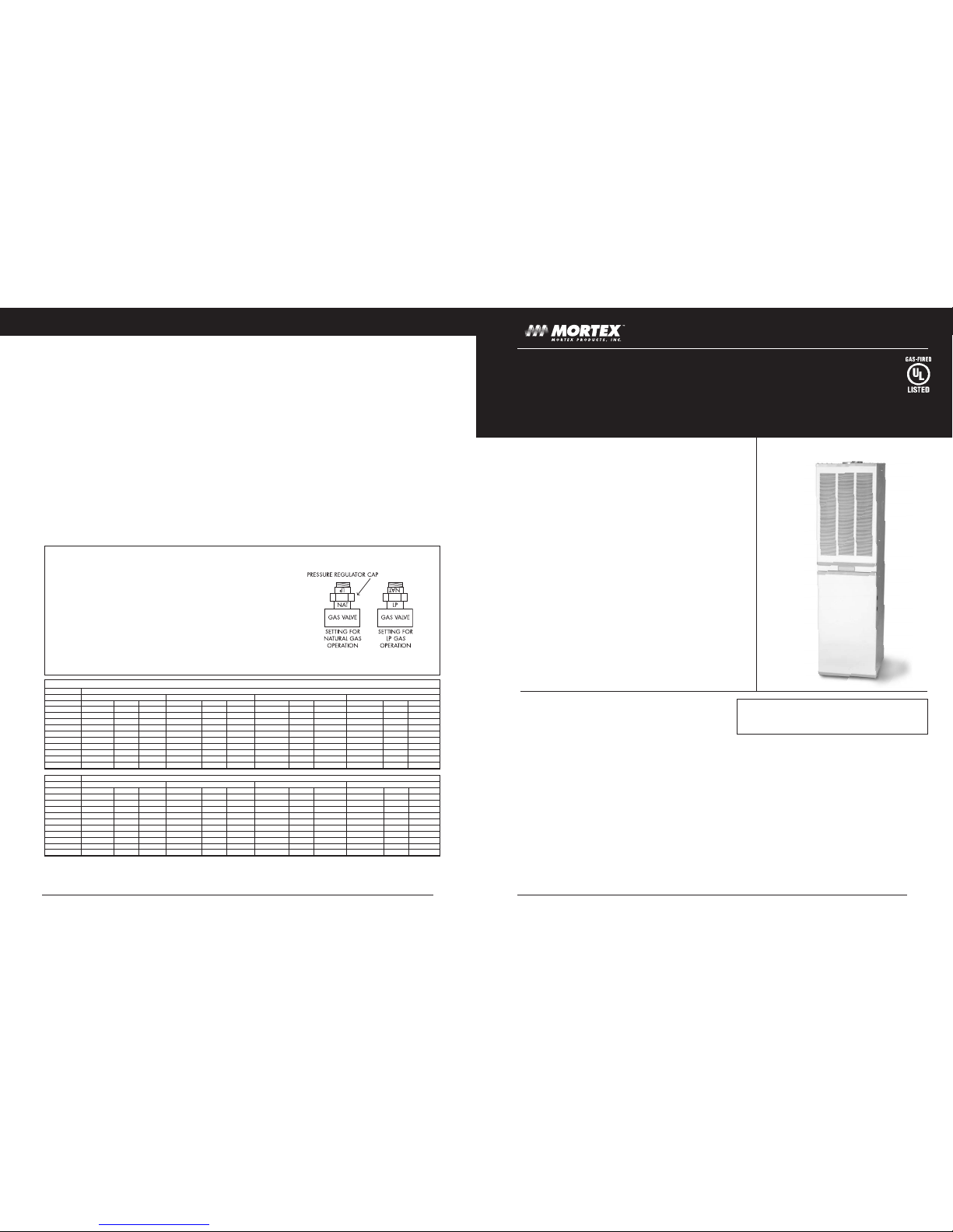
GAS VALVE CONVERSION INSTRUCTIONS
1. Follow instructions “TO TURN OFF GAS TO APPLIANCE”
2. Remove two bolts securing the gas valve bracket. Pull gas valve
valve bracket and burner orifice holder exposing the main burner orifice.
3. Install burner orifice specified on the rating plate for the desired gas.
Conversion parts are in a bag attached to the gas valve.
4. Replace valve, bracket/orifice holder, and bolts.
Attach ID tag for the desired gas adjacent to the gas valve.
Ensure that all connections are tight.
5. Unscrew and reverse the pressure regulating cap so the name of the
desired gas is closest to the valve. See illustration.
HIGH ALTITUDE DERATE CHART- MAIN BURNER ORIFICE SIZE
NATURAL GAS
ELEVATION 60,000 BTUH FURNACE 70,000 BTUH FURNACE 75,000 BTUH FURNACE 90,000 BTUH FURNACE
PART NO ORIF DIA. DRILL SIZE PART NO ORIF DIA. DRILL SIZE PART NO ORIF DIA. DRILL SIZE PART NO ORIF DIA. DRILL SIZE
SEA LEVEL 72AG-147 0.1470 26 72AG-159 0.1590 21 72AG-161 0.1610 20 72AG-180 0.1800 15
2,000 72AG-144 0.1440 27 72AG-154 0.1540 23 72AG-161 0.1610 20 72AG-177 0.1770 16
3,000 72AG-140 0.1405 28 72AG-154 0.1540 23 72AG-159 0.1590 21 72AG-173 0.1730 17
4,000 72AG-140 0.1405 28 72AG-152 0.1520 24 72AG-157 0.1570 22 72AG-173 0.1730 17
5,000 72AG-140 0.1405 28 72AG-149 0.1495 25 72AG-154 0.1540 23 72AG-169 0.1690 18
6,000 72AG-136 0.1360 29 72AG-147 0.1470 26 72AG-152 0.1520 24 72AG-166 0.1660 19
7,000 72AG-136 0.1360 29 72AG-144 0.1440 27 72AG-149 0.1490 25 72AG-161 0.1610 20
8,000 72AG-128 0.1285 30 72AG-140 0.1405 28 72AG-147 0.1470 26 72AG-161 0.1610 20
9,000 72AG-128 0.1285 30 72AG-140 0.1405 28 72AG-144 0.1440 27 72AG-157 0.1570 22
10,000 72AG-128 0.1285 30 72AG-136 0.1360 29 72AG-140 0.1405 28 72AG-152 0.1520 24
LP-PROPANE GAS
ELEVATION 60,000 BTUH FURNACE 70,000 BTUH FURNACE 75,000 BTUH FURNACE 90,000 BTUH FURNACE
PART NO ORIF DIA. DRILL SIZE PART NO ORIF DIA. DRILL SIZE PART NO ORIF DIA. DRILL SIZE PART NO ORIF DIA. DRILL SIZE
SEA LEVEL 72AG-089 0.0890 43 72AG-099 0.0995 39 72AG-101 0.1015 38 72AG-113 0.1130 33
2,000 72AG-086 0.0860 44 72AG-098 0.0980 40 72AG-099 0.0995 39 72AG-110 0.1100 35
3,000 72AG-086 0.0860 44 72AG-096 0.0960 41 72AG-098 0.0980 40 72AG-110 0.1100 35
4,000 72AG-086 0.0860 44 72AG-096 0.0960 41 72AG-096 0.0960 41 72AG-106 0.1065 36
5,000 72AG-082 0.0820 45 72AG-093 0.0930 42 72AG-096 0.0960 41 72AG-106 0.1065 36
6,000 72AG-082 0.0820 45 72AG-093 0.0930 42 72AG-093 0.0930 42 72AG-104 0.1040 37
7,000 72AG-081 0.0810 46 72AG-089 0.0890 43 72AG-093 0.0930 42 72AG-101 0.1015 38
8,000 72AG-078 0.0780 47 72AG-089 0.0890 43 72AG-089 0.0890 43 72AG-101 0.1015 38
9,000 72AG-078 0.0780 47 72AG-086 0.0860 44 72AG-089 0.0890 43 72AG-098 0.0980 40
10,000 72AG-076 0.0760 48 72AG-086 0.0860 44 72AG-086 0.0860 44 72AG-096 0.0960 41
Reference: NFPA No. 54, ANSI Z 223.1 National Fuel Gas Code
Table shows 4% Input Reduction per 1,000 feet elevation.
For Canadian High Altitude (2,000-4,500 feet), reduce gas pressure to burner manifold (manifold Ps.) to 3.0" W.C., and 9.0" W.C. for LP (Propane) Gas
G17D, G18D
Sizes 060-090
WARNING-RISK OF FIRE OF ELECTRICAL SHOCK
Only qualified service personnel shall be used to install
and provide maintenance of this furnace.
P/N: 61GF0011
Page 2
3
Mortex Products, Inc. / FT. WORTH, TX 76106 G17 / G18 Installation Instructions Printed 04/04
2
Mortex Products, Inc. / FT. WORTH, TX 76106 G17 / G18 Installation Instructions Printed 04/04
INSTALLATION INSTRUCTIONS
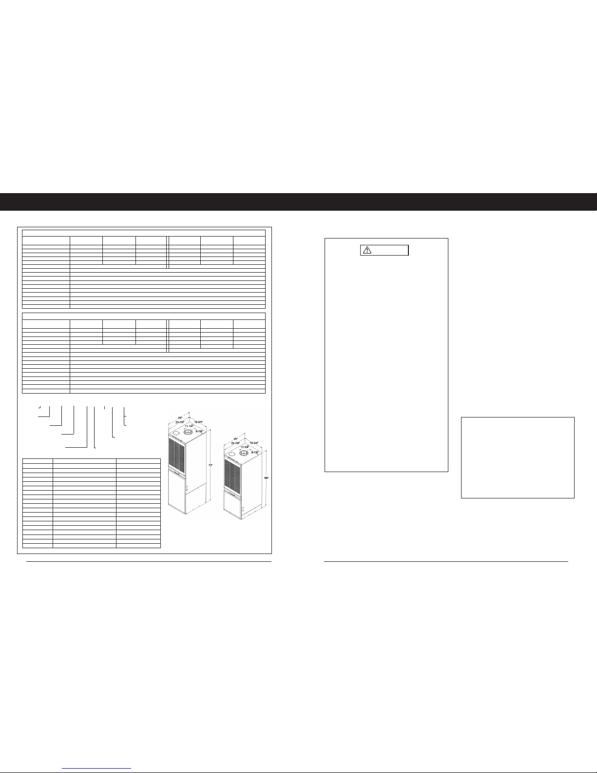
SPECIFICATIONS
“B” Cabinet “A” Cabinet
CAUTION
• ELECTRIC POWER - turn off all electrical power to
furnace before performing any maintenance or
service on unit. Failure to take this precaution may
result in personal injury due to electrical shock.
•
SERVICE - a qualified service technician should
service this unit. Fuel burning appliances can
generate toxic flue products. Modification of the
appliance can cause carbon monoxide in deadly
amounts. To prevent a safety hazard, maintain this
appliance in a safe operating manner and do not
modify.
•
DO NOT modify vent or operate the unit with a
blocked vent or inlet air pipe.
•
DO NOT re-drill a burner orifice. If the orifice size
must be changed, use only a new orifice.
•
DO NOT use matches, lighters, candles, or other
sources of open flame to check for gas leaks.
•
PROPER maintenance for this unit requires certain
mechanical skills and tools. If you are at all
uncertain, contact your Heating Service Co. for
maintenance and service.
•
CONSULT with a service technician for any
problems or questions you may have pertaining to
this appliance.
•
ALWAYS inspect the appliance before starting a
new heating season, paying special attention to vent
pipes and fuel lines.
SAFETY CONSIDERATIONS
NOTE: The words “Shall” or “Must” indicate a
requirement, which is essential to satisfactory and safe
furnace performance.
The words “Should or “May” indicate a recommendation
which may be helpful or enhance performance.
INSTALLATION STANDARDS
CODE COMPLIANCE
The installer shall become familiar with and follow all local
codes and regulations which govern the installation of this
furnace. Where applicable, local codes may take
precedence.
• Federal Manufactured Home Construction and Safety
Standards – HUD Title 24, Part 3280.
• National Fuel Gas Code – ANSI-Z223.1/NFPA-54
• Unit electrical wiring and grounding shall comply with
National Electrical Code – ANSI/NFPA-70.
• “Manufactured Housing” – NFPA-501 and “Fire Safety
Criteria for Mobile Home Installations – NFPA 501A.
• “Recreational Vehicles” – ANSI-119-2/NFPA-501C
HIGH ALTITUDE INSTALLATION
For elevation above 2,000 feet derate furnace input 4% for
each 1,000 feet of elevation above sea level. Furnace
deration is accomplished by reducing the burner orifice
size. See DERATING CHART for orifice size and
CONVERSION INSTRUCTIONS, Page16.
INSTALLATION CLEARANCES
These furnaces are design certified for the following
minimum clearances from combustible materials in alcove
or closet installations.
Locate furnace to ensure adequate room for service access
to all vent connections, controls and the heat exchanger. A
front clearance of 18” minimum (24” recommended) shall
be provided by a closet door or spacing away from a
facing wall or partition.
For installation on combustible flooring (except carpeting)
using manufacturers supplied floor base P/N 87FB0005
and duct connector Series P/N 86AA001-.
Top . . . . . . . . . . . . . . . . . . . . . . . . . . .6 in.
Sides . . . . . . . . . . . . . . . . . . . . . . . . . .0 in.*
Back . . . . . . . . . . . . . . . . . . . . . . . . . .0 in *
Alcove-front of furnace . . . . . . . . . . . . .18 in
Closet- front of furnace . . . . . . . . . . . . . .6 in**
Duct . . . . . . . . . . . . . . . . . . . . . . . . . . .0 in.
Vent/Roof Jack . . . . . . . . . . . . . . . . . . .0 in.
* If the return air opening is below the top of
the furnace, clearance to the side or rear shall
be 6”.
** See Return Air for clearances less than 6”.
PART NO. DESCRIPTION NOTES
90-RJF1729-AL Body, Roof Jack, Gas-FLAT Height 'A'- 73 in.- 85 in.
90-RJF2551-AL Body, Roof Jack, Gas-FLAT Height 'A'- 81 in. - 107 in.
90-RJS1729-AL Body, Roof Jack, Gas-SLOPE 3/12 Height 'B'- 81 in. - 101 in.
90-RJS2551-AL Body, Roof Jack, Gas-SLOPE 3/12 Height 'B'- 97 in. - 123 in.
90-RJS3868-AL Body, Roof Jack, Gas-SLOPE 3/12 Height 'B'- 110 in. - 140 in.
90-RJS6399-AL Body, Roof Jack, Gas-SLOPE 3/12 Height 'B'- 135 in.- 171 in.
90-RJCRWN-AL Crown, Roof Jack, Gas Use w/ Gas Roof Jack Body
90-TRM-RNG Ceiling Trim Ring, Roof Jack Trim out to inside RJ- pipe
90-RJTRC Kit, Transit- Roof Jack--Cap & Labels for transport-remove on site
90-OUTXT16-AL Roof Jack Outdoor Extension-Gas 16" Extend pipes/crown-16 in.
90-INSXT10-AL Roof Jack Inside Extension-Gas 10" Extend inside pipes-10 in.
90-RJS56 5-6/12 Slope, Roof Saddle Adapter Add to RJS 3/12 Roof Jack
90-DCUO-OI 86AA0013 Duct Conn + 87FB0005 Flr Base Floor to Duct- 1 in.-4 in.
90-DCUO-O2 86AA0014 Duct Conn + 87FB0005 Flr Base Floor to Duct- 6 in.-8 in.*STD
90-DCUO-O3 86AA0015 Duct Conn + 87FB0005 Flr Base Floor to Duct- 8 in.-12 in.
90-CABEXT4 White, Top, Cabinet Extender Plate Fill alcove 76" top opening
90-BLWRELAY Blower Relay/Wiring Kit Convert Furn for A/C
87-1008-3/12A1 A/C Blower, 3 Speed-1/3 HP 2-4 Ton A/C
87-1008-4/16A1 A/C Blower, 4 Speed-3/4 HP 2-5 Ton A/C
PRODUCT CODE
ACCESSORIES
G1 8D075 B - A 3/12
G=GAS NOM CFM-HI SPEED, W/COIL
DASH @ 0.3" W.C Ext SP (DUCT)
1=SERIES 10-1010, 12-1180, 16-1620
7=75, 8=80 AFUE 1,2,3,4- MOTOR SPEEDS
D=DNFLO, MANUFTR-MOD A=A/C BLOWER & RELAY
H=HEAT or 3T BLW READY, NO RELAY
060,070,075,090 BTUH INPUT A=56", B=72" TALL FURN CABINET
80 AFUE- AUTOMATIC HOT SURFACE IGNITION
Model No. G18D060A-H2/10 G18D075A-H2/10 G18D090A-H2/10 G18D060B-A3/12 G18D075B-A3/12 G18D090B-A3/12
Input, BTUH 60,000 75,000 90,000 60,000 75,000 90,000
Output, BTUH 48,000 61,000 72,000 48,000 61,000 72,000
AFUE, % 80.0 81.0 80.0 80.0 81.0 80.0
With A-Coil Cabinet NO NO NO YES YES YES
Ignition Type Auto-Elect Auto-Elect Auto-Elect Auto-Elect Auto-Elect Auto-Elect
Air Temperature Rise, Range-F 40-70 45-75 50-80 40-70 45-75 50-80
Blower-Heat or Heat/Cool Heat Heat/Cool -4T
Designed Max Outlet Air Temp-F 165
Max. External SP (Duct), In. W.C. 0.30
Factory Equipped Fuel Natural Gas
High Altitude For elevations above 2,000 feet, reduce input 4% for each 1,000 ft. elevation above sea level
Furnace Flue Pipe Must Use RJS or RJF Roof Jack
Gas Connection 1/2" NFPT
Electric Service 120VAC, 60Hz, 1 Ph
Fuse or Circuit Breaker 15 Amp
Thermostat Circuit 24VAC, 60Hz, 40VA
Filters 2-16"x20"x1"
75 AFUE- STANDING PILOT IGNITION NOTE: Blower Drives- H2/10, A3/12 , A4/16 listed with all G17D-G18D furnace models.
Model No. G17D060B-H2/10 G17D070B-H2/10 G17D090B-H2/10 G17D060B-A3/12 G17D070B-A3/12 G17D090B-A3/12
Input, BTUH 60,000 70,000 90,000 60,000 70,000 90,000
Output, BTUH 48,000 55,000 71,000 48,000 55,000 71,000
AFUE, % 76.0 75.0 76.0 76.0 75.0 76.0
With A-Coil Cabinet YES YES YES YES YES YES
Ignition Type Pilot Pilot Pilot Pilot Pilot Pilot
Air Temperature Rise, Range-F 45-75 45-75 50-80 45-75 45-75 50-80
Blower-Heat or Heat/Cool Heat/3T Blower Ready, No AC Controls Heat/Cool -4T
Designed Max Outlet Air Temp-F 165
Max. External SP (Duct), In. W.C. 0.30
Factory Equipped Fuel Natural Gas
High Altitude For elevations above 2,000 feet, reduce input 4% for each 1,000 ft. elevation above sea level
Furnace Flue Pipe Must Use RJS or RJF Roof Jack
Gas Connection 1/2" NFPT
Electric Service 120VAC, 60Hz, 1 Ph
Fuse or Circuit Breaker 15 Amp
Thermostat Circuit 24VAC, 60Hz, 40VA
Filters 2-16"x20"x1"
Page 3
5
Mortex Products, Inc. / FT. WORTH, TX 76106 G17 / G18 Installation Instructions Printed 04/04
4
Mortex Products, Inc. / FT. WORTH, TX 76106 G17 / G18 Installation Instructions Printed 04/04
INSTALLATION INSTRUCTIONS
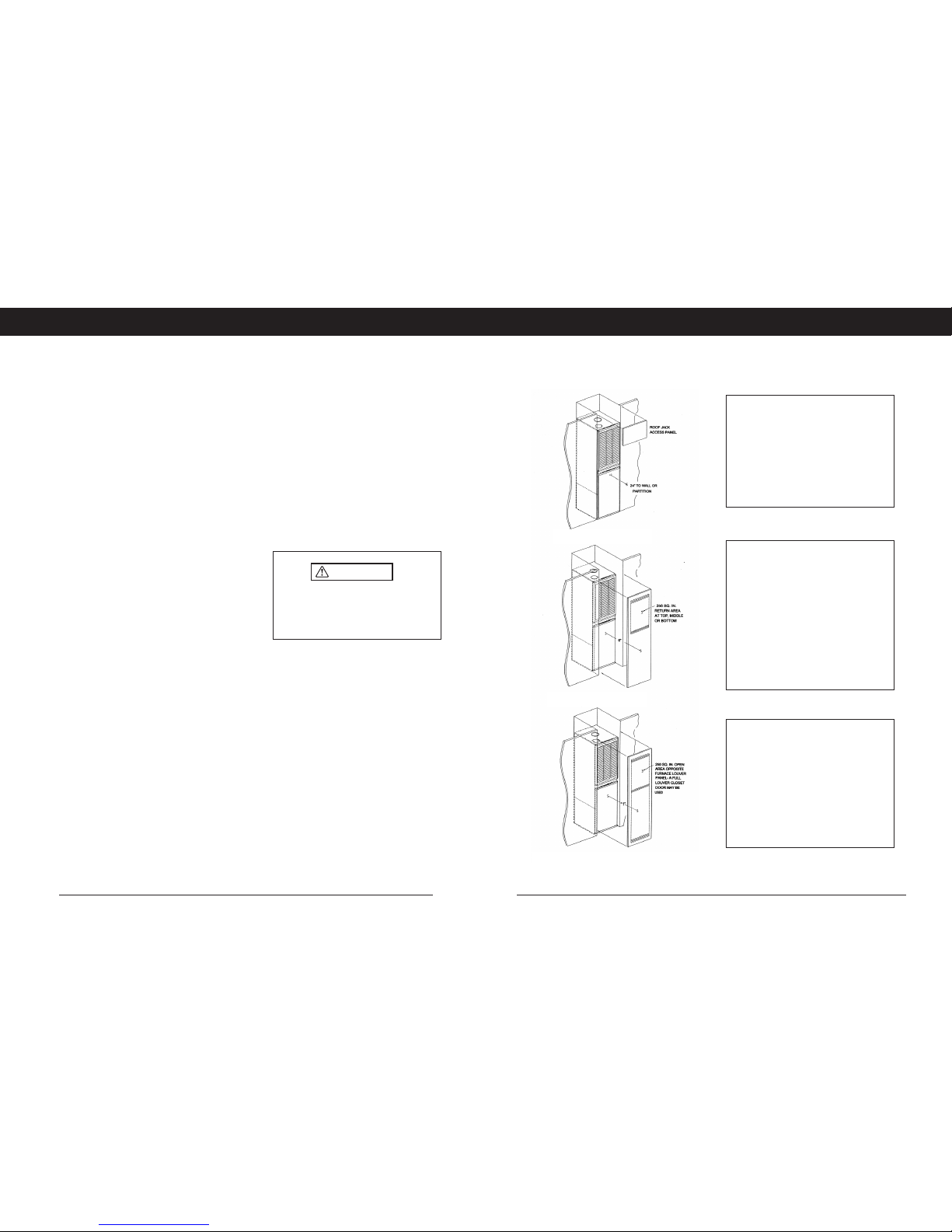
RETURN AIR
ALCOVE INSTALLATION
The furnace may be installed free standing or in an alcove
with a free flow of air back to the furnace. A minimum of
18” shall be provided at the front for return air and service
access.
CLOSET INSTALLATION - 6 in.
NOTE: If return air is through a side wall, there must be a
minimum of 6-in. clearance from side wall to furnace in
addition to 6-in. minimum clearance from inside of closet
door to front of furnace.
If a louvered door complying with the minimum air requirements is used, the front clearance may be reduced to 1”.
CLOSET INSTALLATIONS
Additional Requirements
Concerning under floor or ceiling return air systems, the
following items (1-10) must be adhered to:
1. The return-air opening into the closet, regardless of
location, is to be sized not less than specified on the
appliance rating plate.
2. If the return-air opening is located in the floor of the
closet (versus the vertical front or side wall), the
opening is to be provided with means to prevent its
inadvertent closure by a flat object placed over the
opening.
3. The cross-sectional area of the return duct system
(when located in the floor or ceiling of the
manufactured home) leading into the closet is to be not
less than that of the opening specified on the appliances rating plate.
4. The total free area of openings in the floor or ceiling
registers serving the return-air duct system is to be not
less than 150% of the size opening specified on the
appliance rating plate. At least one such register is to
be located where the likelihood of its being covered by
carpeting, boxes, and other objects is minimized.
5. Materials located in the return duct system have a
flame spread classification of 200 or less.
6. Non-combustible pans having one-inch upturned
flanges are located beneath openings in the floor
return duct system.
7. Wiring materials located in the return duct system
conform to Article 300-22 (B&C) of the National
Electric Code, ANSI / NFPA-70.
8. Gas piping is not run in or through the return duct
system.
9. The negative pressure in the closet, as determined
by test with the air-circulating fan operating at high
heating speed and the closet door closed, is to be not
more negative than minus 0.05-inch water column.
10. For floor return systems, the manufactured home
manufacturer or installer shall affix a prominent
warning where it is easily read when the closet door is
open.
The marking shall read:
HAZARD OF ASPHYXIATION
DO NOT COVER OR RESTRICT FLOOR
OPENING, or equivalent
WARNING
RETURN AIR
ALCOVE
A minimum of 18” front clearance to a facing
wall or partition is needed for service access
and return air.
Provide a removable panel above the furnace
for access to roof jack and pipe connections on
top of the furnace.
CLOSET - 6” CLEARANCE
A minimum of 250 sq. in free open area return
opening is required to the closet. The return
opening may be anywhere on or above the
closet door. If the return is through a side wall,
and the opening is below the top of the furnace,
a minimum of 6-in. clearance from side wall to
furnace must be provided in addition to 6-in
minimum clearance from inside of closet door to
furnace.
If a 5T A/C will be installed, the return shall be
increased to 390-sq. in. open area.
SPECIAL-CLOSET, 1” CLEARANCE
For closet installations with less than 6-in.
clearance from inside of closet door to furnace,
a louvered closet door must be used with a min.
of 250 sq. in open area directly in line with the
furnace top louver panel as shown. A fully
louvered closet door may be used.
If a 5T A/C will be installed, the return shall be
increased to 390 sq. in open area directly in
line with the furnace louver panel.
ALCOVE INSTALLATION
CLOSET INSTALLATION
*SPECIAL - 1”- 6” CLOSET INSTALLATION
Page 4
7
Mortex Products, Inc. / FT. WORTH, TX 76106 G17 / G18 Installation Instructions Printed 04/04
6
Mortex Products, Inc. / FT. WORTH, TX 76106 G17 / G18 Installation Instructions Printed 04/04
INSTALLATION INSTRUCTIONS
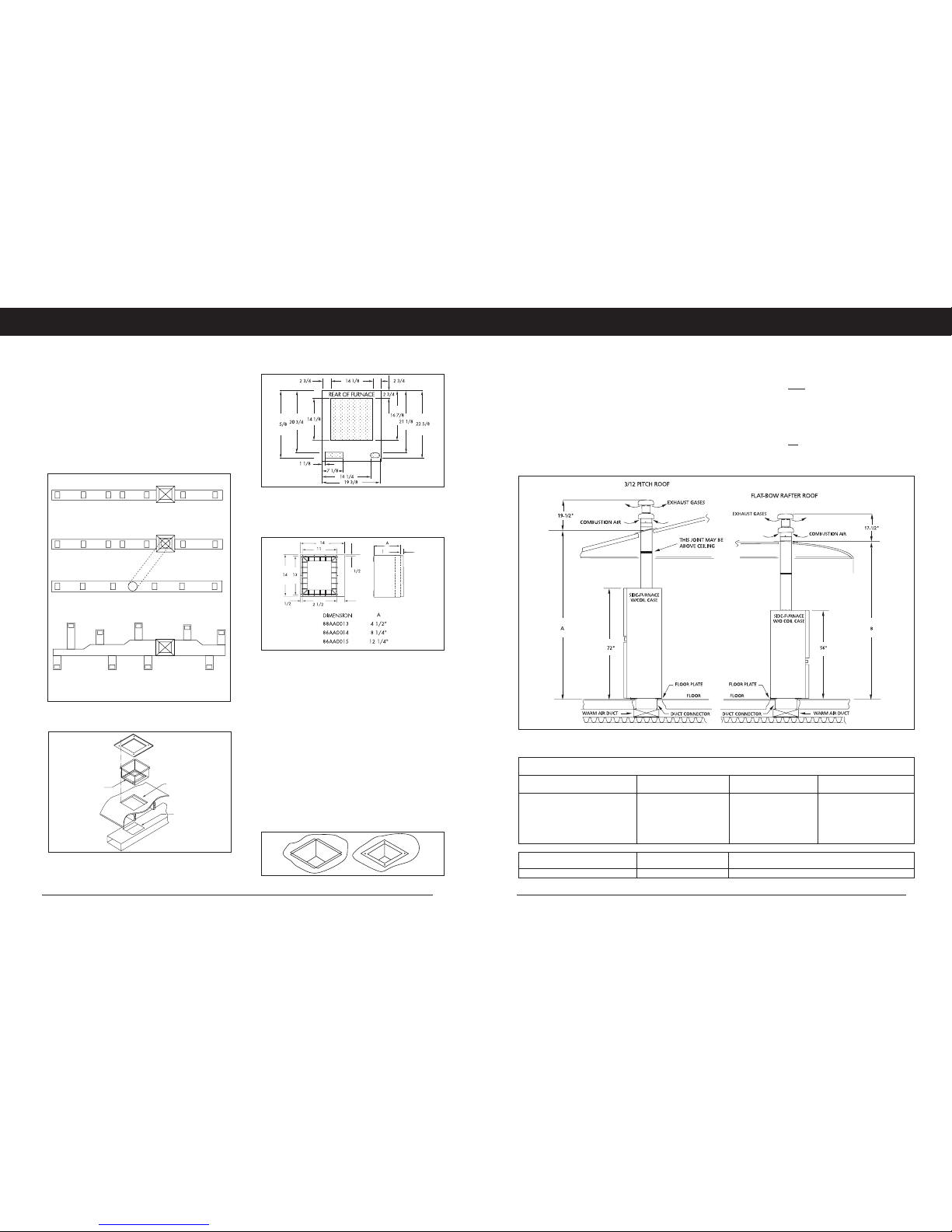
AIR DISTRIBUTION SYSTEMS
The supply duct system must be designed so that static
pressure in the duct does not exceed the static pressure listed on the furnace rating plate. Location, size and number of
registers should be selected on the basis of best air
distribution and floor plan of the home. A manual to
review before selecting a duct system is Manufactured
Housing Duct Systems: Guide to Best Practices by
Manufactured Housing Research Alliance (MHI-MHRA).
Typical duct systems are shown below: FIG. A, B, C
DUCT CONNECTOR / BASE INSTALLATION
The furnace may be on combustible flooring (expect
carpeting) when installed with 86AA001Duct Connector and 87FB0005 Floor Base.
1. Cut a 14-1/8 x 14-1/8 opening in floor. Fig. D.
FIG.D Duct Connector Opening, Fuel & A/C Lines
2. Orient duct connector to align 11x13 tabbed
opening with floor duct. See FIG. E
FIG. E- 86AA001- Duct Connector
1. Place duct connector tab end down, thru floor
opening to rest on top duct surface.
2. Use eight (8) oval holes on tab surfaces as locators and
mark for 11x13 duct opening; remove duct connector.
3. Connect marks with straight lines and cut out the duct
opening slightly outside the lines.
4. Attach four (4) foam tape gaskets (provided) to duct
connector alongside tabs for a 11x13 perimeter seal.
5. Replace duct connector/gaskets through floor opening.
6. Bend tabs down into the duct opening and fold back
180 degrees, securing duct connector. Add screws if
needed.
7. Slit the 4 corners of the connector extending above the
floor. Bend sides over onto the floor surface. Fig. F
8. Install floor base over floor opening with 13x13
flanges down. Nail to floor thru 4 holes. Fig. G
INSTALL FURNACE
Prior to installing furnace, fuel and A/C line openings may
be cut in. See FIG.D
1. Remove upper and lower furnace doors.
2. Slide furnace onto floor base and push back until
cabinet is against rear flange of floor base.
3. Secure furnace to floor with fasteners/screws at right
and left front inside corners of cabinet.
4. Attach pipe strap at top of furnace to alcove or closet
framing, or fasten through furnace front edge cabinet
sides to wood framing.
RJ - SERIES ROOF JACK
G17D and G18D are sealed combustion furnaces tested
and listed for use
only with RJ - Series Roof Jack
Venting System.
Furnace exhaust gases vent outdoors
through the inner pipe of the RJ - Series “pipe-within-a-pipe”
vent system. The space between the outer and inner pipes is
used to bring in outside combustion air for the burner.
WARNING: Do not install furnace with any other
type of venting system.
A HAZARDOUS CONDITION
MAY RESULT.
FIG. H - RJ SERIES ROOF JACK
FIG. A - Single trunk duct with in-line registers
FIG. B - Double duct with in line registers and
crossover duct
FIG. C - Graduated Single Trunk with perimeter
registers
FLOOR BASE
DUCT
CONNECTER
FOLD-OVER
TABS
14-1/8" X 14-18"
FLOOR CUTOUT
11" X 12" DUC
T
OPENING
MAIN TRUNK
FIG. F FIG. G
THE SEALED COMBUSTION VENT SYSTEM CONSISTS OF: FURNACE SERIES FURNACE SERIES
ROOF JACK BODY AND ROOF JACK CROWN G18D-A , 56" H G17D-B, G18D-B, 72" H
PART NO. FOR: FLAT OR "A" "B"
ROOF JACK BODY SLOPE ROOF ADJUSTABLE HEIGHT ADJUSTABLE HEIGHT
90-RJF1729-AL FLAT 73"- 85 " 89" - 101"
90-RJF2551-AL FLAT 81"- 107" 97" - 123"
90-RJS1729-AL 3/12 73" - 85 " 89" - 101"
90-RJS2551-AL 3/12 81" - 107" 97" - 123"
90-RJS3868-AL 3/12 94" - 124" 110" - 140"
90-RJS6399-AL 3/12 119" - 155" 135" - 171"
PART NO. MUST USE
ROOF JACK CROWN WITH:
90-RJCRWN-AL ROOF JACK BODY
Page 5
9
Mortex Products, Inc. / FT. WORTH, TX 76106 G17 / G18 Installation Instructions Printed 04/04
8
Mortex Products, Inc. / FT. WORTH, TX 76106 G17 / G18 Installation Instructions Printed 04/04
INSTALLATION INSTRUCTIONS
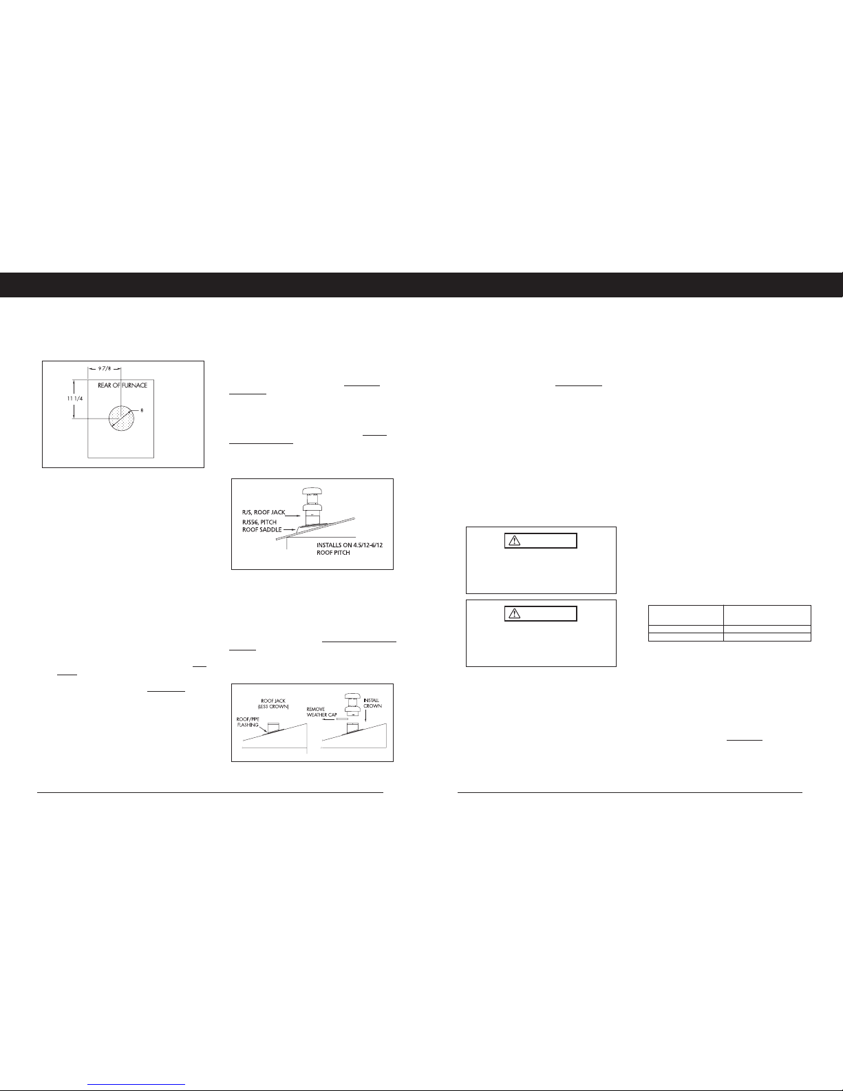
CUTTING ROOF JACK OPENING
A proper installation of the roof jack requires that openings
in roof and ceiling be on the same vertical centerline as the
furnace flue collar. See FIG. I
FIG. I - ROOF CUT-OUT
Mark the center point on the ceiling and scribe a 4” radius
(8” diameter) around this mark. If furnace is in place during
this step, cover the furnace and flue opening to prevent
debris from entering flue.
INSTALLING ROOF JACK
The roof jack body should be secured to the furnace before
the roof flashing is secured to the roof.
1. Insert roof jack body into opening in the roof.
2. From above, center the roof jack body aligning with
the furnace collar.
3. From inside the home, pull down 4-3/16” D flue
pipe seating the pipe fully and firmly over the
furnace flue collar.
4. Next pull down the 7” D combustion air pipe seating
it over the mating furnace collar. Rotate the
combustion air pipe lining up to the screw hole on the
7” furnace collar.
5. Check and make sure the combustion air pipe is fully
seated.
Then drive a #10 sheet metal screw attaching
pipe firmly to furnace collar.
6. Install optional ceiling trim ring, 90-TRM-RNG
7. On the roof, caulk liberally under the roof jack
flashing.
8. Drive nails or screws through the flashing onto the
roof surface about 1- 1 _ inches apart. Caulk again
to ensure a leak tight joint.
9. Install roof jack crown and fasten to roof jack body
with three (3) screws (provided) using pre-punched
holes.
INSTALLATION IN SNOW REGIONS
When the combustion air inlet to the roof jack is blocked
with snow, the furnace will not operate properly due to the
depleted combustion air supply.
Therefore, if the furnace will be located in regions where
snow accumulation on the roof exceeds 7” or in H.U.D.
Snow Load Zones, a roof jack extension- Par
t No. 90-
0UTXT16-AL- is recommended.
ROOF JACK ON HI-PITCH ROOF
To install the RJS (3/12) Series Roof Jack on roofs which
have a slope between 4.5/12 - 6/12, install a Par
t No.
90-RJS56 Roof Saddle, Fig. J. The combined assembly of
the RJS Roof Jack and Roof Saddle will conform to the
higher roof pitch. If roof pitch is greater than 6/12, field
fabricate a suitable adapter, or consult with factory.
FIG. J - 90-RJS56 ROOF SADDLE, HI PITCH ROOF
TRANSIT ROOF JACK - MODE
RJF and RJS Roof Jacks feature a removable top crown. The
crown is normally installed at the factory. If road clearance
for the home requires that vent caps or crowns remain
uninstalled for road clearance, a T
ransit Mode Kit, Part No.
90-RJTRC
is available. The kit, when used, allows for home
shipment with the crown shipped inside the home. The kit
includes a weather cap and four (4) warning tags.
FIG. K - 90-RJTRC TRANSIT MODE INSTALLATION
INSTALL TRANSIT ROOF JACK
AT MANUFACTURED HOME FACTORY
1. Roof Jack body (less crown) installed per instructions
in this manual.
2. Install weather cap from 90-RJTRC kit on RJF or RJS
upper body.
3. The 3 warning tags supplied must be attached
as
follows:
• To homes gas line connection point
• To furnace gas control valve
• To furnace wall thermostat
4. Upper crown, in original carton must be stored in a
prominent location inside the home until crown
installation is made at site location.
AT MANUFACTURED HOME SITE
5. The transit weather cap is removed and
6. 90-RJCRWN-AL crown installed per these instructions.
See FIG K. Make sure crown engages RJ-body pipes
above the roof and crown is secured with 3 sheet
metal screws.
7. Transit system warning tags are discarded.
CONNECT POWER SUPPLY
1. Remove the furnace control panel cover.
2. Insert 115 V wiring through a strain relief bushing on
the left side of the furnace.
3. Connect the HOT wire to the BLACK pigtail lead;
connect the NEUTRAL wire to the WHITE pigtail lead.
Secure the connections with suitable wire nuts and
wrap with electrical tape. Refer to Pgs. 11 thru 13 and
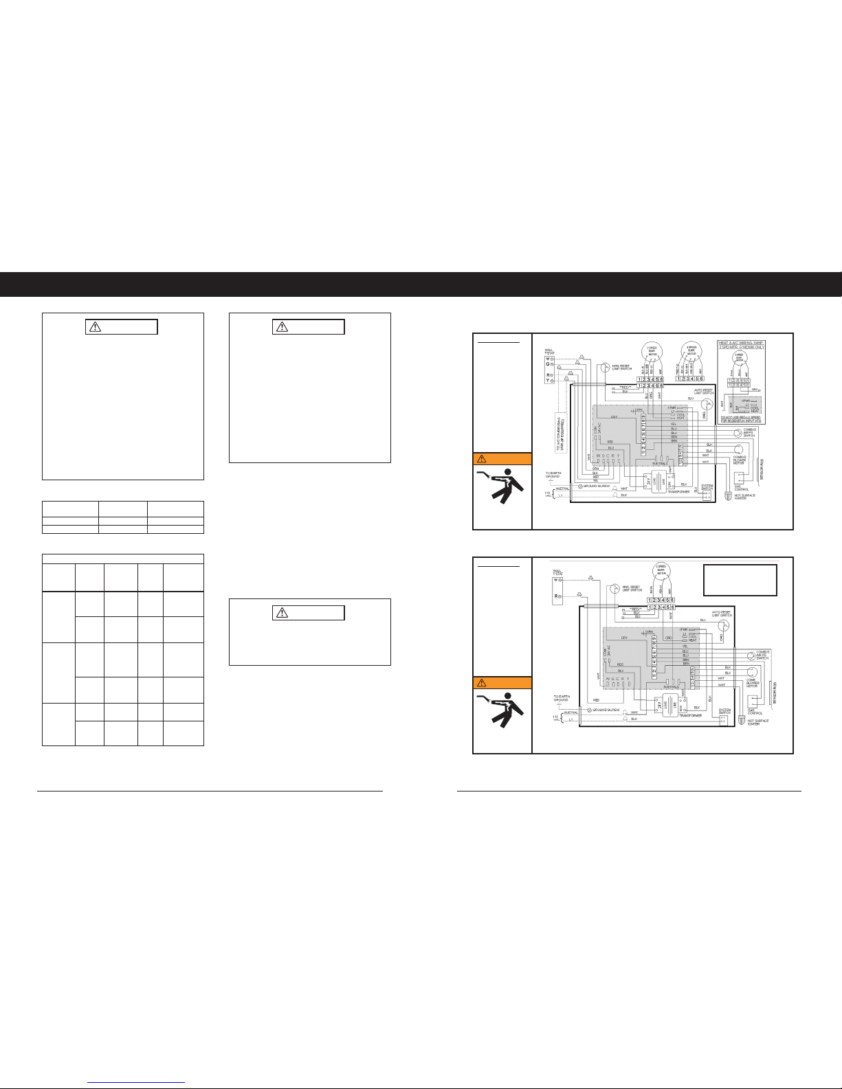
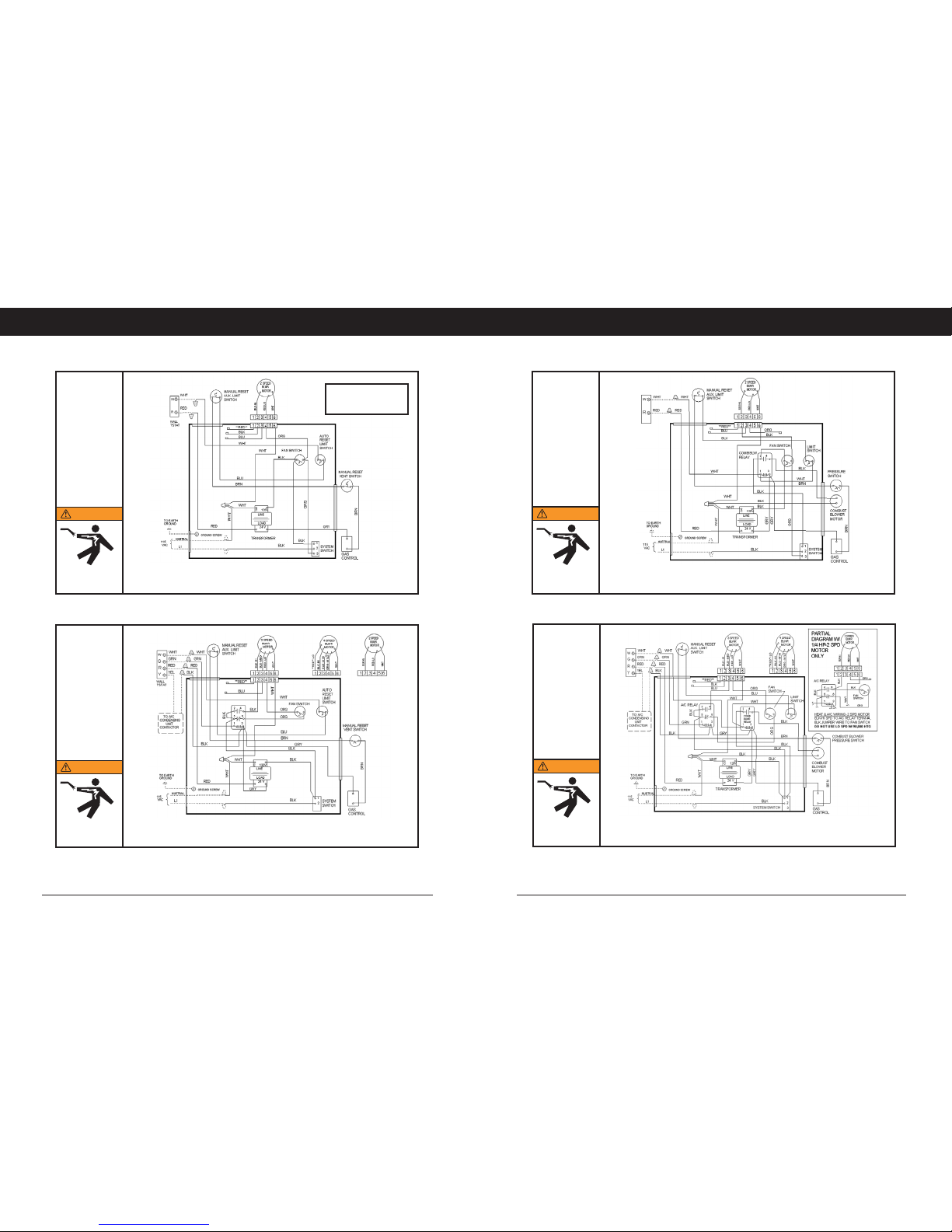
one of the following Fig’s L,M,N,O,P or Q to select the
proper wiring diagram for connections
4. Connect the GROUND wire to a grounding screw in
the control panel.
5. Reinstall and secure the control panel cover
with screws.
WALL THERMOSTAT
The location of the wall thermostat is important, as it must
sense the desired temperature of the entire conditioned
space. Choose a location 4-5 feet above the floor,
preferably on an inside wall in an area with good air
circulation. Stay away from lamps and air registers and do
not install behind a door. Choose a location where the
temperature will be reasonably representative of other living
areas the thermostat is controlling.
CONNECT THERMOSTAT WIRES
When installing a furnace with a cooling coil compartment,
use of a five-conductor thermostat cable is recommended.
This will allow easy installation of an air conditioning system at a later date.
1. Insert 24V wires through the small plastic bushing on
the left side of the furnace.
2. Connect low voltage wires to the color coded low
voltage pigtails at top of the control panel.
3. Connect low voltage wires to the wall thermostat.
NOTE: The use of 18-gauge wire is highly recommended to
carry the thermostat load. Use of smaller conductors risks
operational problems caused by loose or broken conductors
or wire that is too small to carry the load. Any such
problems are the responsibility of the installer.
With conductors smaller than 18 gauge, observe the
following guidelines.
Thermostat wire length
-furnace to thermostat- Thermostat wire gauge
0-45 feet 22
0-70 feet 20
GAS PIPING
Supply piping must be sized in accordance with
recommendations found in National Fuel Gas Code ANSI
Z223.1/NFPA-54. In addition materials used in manufactured
homes must comply with requirements contained in HUD
Title 24, Section 3280.705 as well as A119.1 and A119.2
for recreational vehicles.
See chart in this manual for minimum sizes for NAT and LP
pipe and tubing serving the fur
nace only.
NOTE: The gas inlet on the gas control valve is 1/2-14NPT.
The gas line may be installed through the bottom casing or
on left or right side of furnace.
WARNING
Any attempt to operate furnace before replacing
transit-mode Weather Cap with Roof Jack Crown
may result in hazard of fire, explosion or
asphyxiation.
WARNING
To avoid electric shock, personal injury, or death,
turn off the power at the disconnect or the main
service panel before making any electrical
connections.
Page 6
11
Mortex Products, Inc. / FT. WORTH, TX 76106 G17 / G18 Installation Instructions Printed 04/04
10
Mortex Products, Inc. / FT. WORTH, TX 76106 G17 / G18 Installation Instructions Printed 04/04
INSTALLATION INSTRUCTIONS
GAS PRESSURE:
TYPE GAS INLET GAS PRESSURE
PRESSURE TO BURNER
NATURAL 7” W.C. 3-1/2” W.C.
PROPANE 11” W.C. 10” W.C.
OPERATION - Once system gas piping has been checked
for leaks, operate the furnace using the lighting instructions
on the front furnace panel, and:
1. Observe burner through viewport and make sure it
ignites. The color of the flame when operating on
natural gas will turn blue with yellow tips. On
Propane, a significantly yellow flame can be
expected. If flame is not the proper color call a
qualified service technician for service.
2. Let furnace operate until blower cycles on. This takes
about 2 to 2 1/2 minutes.
3. Turn thermostat down.
4. Observe burner to make sure it has shut off.
5. Let furnace cool and blower cycle off.
IF FURNACE FAILS TO OPERATE PROPERLY:
1. Check setting on wall thermostat and the position of
the HEAT-COOL switch if air conditioning is installed.
2. Check to make sure that electrical power is ON at
the furnace and the furnace circuit breaker has not
tripped.
3. Make sure that filters are clean and return grills are
not obstructed. The supply registers should be open.
4. Be sure that the furnace flue and inlet piping has not
been obstructed and is open. If the cause for failure
is not obvious, do not attempt to service the furnace
yourself. Call a qualified service agency or the gas
supplier.
Take care when connecting the gas line to the furnace
gas valve. Use suitable wrenches to support the gas
valve when tightening fittings to prevent mis-alignment
of the attached burner orifice. Do not damage the
gas valve as improper heating, explosion, fire or
asphyxiation may result.
Do not use matches, lighters, candles or other open
flame to check for leaks. Use a soap or water solution
or a leak detector.
Do not pressure test the fuel system at more than 14”
W.C. pressure once furnace has been connected to
the gas line. Overpressure may void the warranty
and damage the valve which could cause an explosion, fire or asphyxiation.
WARNING
When converting gas control valve from or to
Propane gas, it will be necessary to change the main
burner orifice to prevent an underfired or overfired
condition. The pressure regulator on the gas control
valve must also be converted. See label on lower
furnace compartment for full instructions.
If the gas input to the furnace is too high due to
excessive gas pressure, wrong size burner orifice, no
orifice, high altitude, etc., the burner flame will be
sooty especially with Propane gas. This type of
furnace operation can produce carbon monoxide,
which could result in unsafe operation, explosion,
and/or fire and asphyxiation.
WARNING
Should overheating occur, or the gas supply fail to
shut off, shut off the manual gas valve to the furnace
and allow burner to run until furnace cools down and
blower shuts off before shutting off electrical supply.
WARNING
WAR NING
DIAGNOSTIC CODES:
STEADY ON -
NORMAL OPERATION
ONE FLASH -
IGNITION FAILURE
TWO FLASHES -
COMBUSTION AIR
SWITCH STUCK CLOSED
THREE FLASHES -
COMBUSTION AIR
SWITCH FAILED TO CLOSE
FOUR FLASHES -
LIMIT SWITCH OPEN
FIVE FLASHES -
GAS VALVE ENERGIZED
WITH NO CALL FOR HEAT
RAPID FLASHES -
REVERSED POLARITY
ELECTRIC SHOCK HAZARD
Disconnect all electric power
before servicing.
1. Incoming wire must be polarized. Observe color coding.
2. If any of the original wires must be replaced, use 105C
Thermoplastic type wire or its equivalent.
3. **RED** = Lo Speed - 4 Speed Motor Only
GAS, HOT SURFACE IGNITION - G18D
P/N 61GFC001
Mortex Products, Inc. / FT. WORTH, TX 76016
WAR NING
DIAGNOSTIC CODES:
STEADY ON -
NORMAL OPERATION
ONE FLASH -
IGNITION FAILURE
TWO FLASHES -
COMBUSTION AIR
SWITCH STUCK CLOSED
THREE FLASHES -
COMBUSTION AIR
SWITCH FAILED TO CLOSE
FOUR FLASHES -
LIMIT SWITCH OPEN
FIVE FLASHES -
GAS VALVE ENERGIZED
WITH NO CALL FOR HEAT
RAPID FLASHES -
REVERSED POLARITY
ELECTRIC SHOCK HAZARD
Disconnect all electric power
before servicing.
1. Incoming wire must be polarized. Observe color coding.
2. If any of the original wires must be replaced, use 105C
Thermoplastic type wire or its equivalent.
3. **RED** = Lo Speed - 4 Speed Motor Only
GAS, HOT SURFACE IGNITION G18D060A-G18D075A-G18D090A
P/N 61GFC002
Mortex Products, Inc.
FT. WORTH, TX 76016
H 2/10, 1/4 HP, 2 SPD BLOWER HEATING SPEED SELECTION
G18D060, G18D075-LO OR HI SPEED TAP
G18D090-HI SPEED TAP ONLY
FIG. L - G18D060B, G18D075B, G18D090B - A/C READY
WIRING DIAGRAMS
FIG. M - G18D060A, G18D075A, G18D090A - HEATING ONLY
GAS PIPE AND TUBING-MIN SIZES
MODEL TYPE LENGTH PIPE TUBING
G17D OF SIZE SIZE
G18D GAS (FT.) (IN.) (IN.OD)
to 20 3/8 5/8
Natural to 60 1/2 -
060 to 70 - 3/4
to 40 3/8 -
Propane to 70 - 5/8
to 80 1/2 -
to 20 - 5/8
to 50 1/2 -
Natural to 60 - 3/4
072 to 80 3/4 075 to 30 3/8 -
Propane to 60 - 5/8
to 80 1/2 to 40 1/2 3/4
Natural to 50 - 3/4
090 to 30 3/8 -
Propane to 40 - 5/8
to 60 1/2 3/4
Page 7
13
Mortex Products, Inc. / FT. WORTH, TX 76106 G17 / G18 Installation Instructions Printed 04/04
12
Mortex Products, Inc. / FT. WORTH, TX 76106 G17 / G18 Installation Instructions Printed 04/04
INSTALLATION INSTRUCTIONS
WAR NING
ELECTRIC SHOCK HAZARD
Disconnect all electric power
before servicing.
1. Incoming wire must be polarized. Observe color coding.
2. If any of the original wires must be replaced, use 105C
Thermoplastic type wire or its equivalent.
3. **RED** = Lo Speed - 4 Speed Motor Only
GAS, PILOT, ATMOSPHERIC FURNACE
MODELS G17D060, G17D070
P/N 61GFC003
Mortex Products, Inc. / FT. WORTH, TX 76016
WAR NING
ELECTRIC SHOCK HAZARD
Disconnect all electric power
before servicing.
1. Incoming wire must be polarized. Observe color coding.
2. If any of the original wires must be replaced, use 105C
Thermoplastic type wire or its equivalent.
3. **RED** = Lo Speed - 4 Speed Motor Only
GAS, PILOT, ATMOSPHERIC FURNACE
A/C READY - MODELS G17D060, G17D070
P/N 61GFC004
Mortex Products, Inc.
FT. WORTH, TX 76016
H 2/10, 1/4 HP, 2 SPD BLOWER HEATING SPEED SELECTION
G17D060, G17D070 LO OR HI SPEED TAP
FIG. N - G17D060, G17D070 - W/PILOT, HEATING
FIG. O - G17D060B, G17D070B - W/PILOT, A/C READY
FIG. Q - G17D090B - W/PILOT, A/C READY
FIG. P - G17D090 - W/PILOT, HEATING
WAR NING
ELECTRIC SHOCK HAZARD
Disconnect all electric power
before servicing.
1. Incoming wire must be polarized. Observe color coding.
2. If any of the original wires must be replaced, use 105C
Thermoplastic type wire or its equivalent.
3. **RED** = Lo Speed - 4 Speed Motor Only
GAS, PILOT, W/ COMBUSTION BLOWER
A/C READY - MODEL G17D090
P/N 61GF0006
Mortex Products, Inc. / FT. WORTH, TX 76016
WAR NING
ELECTRIC SHOCK HAZARD
Disconnect all electric power
before servicing.
1. Incoming wire must be polarized. Observe color coding.
2. If any of the original wires must be replaced, use 105C
Thermoplastic type wire or its equivalent.
3. **RED** = Lo Speed - 4 Speed Motor Only
GAS, PILOT, W/ COMBUSTION BLOWER
HEATING - MODEL G17D090
P/N 61GFC005
Mortex Products, Inc. / FT. WORTH, TX 76016
WIRING DIAGRAMS WIRING DIAGRAMS
Page 8
15
Mortex Products, Inc. / FT. WORTH, TX 76106 G17 / G18 Installation Instructions Printed 04/04
14
Mortex Products, Inc. / FT. WORTH, TX 76106 G17 / G18 Installation Instructions Printed 04/04
INSTALLATION INSTRUCTIONS
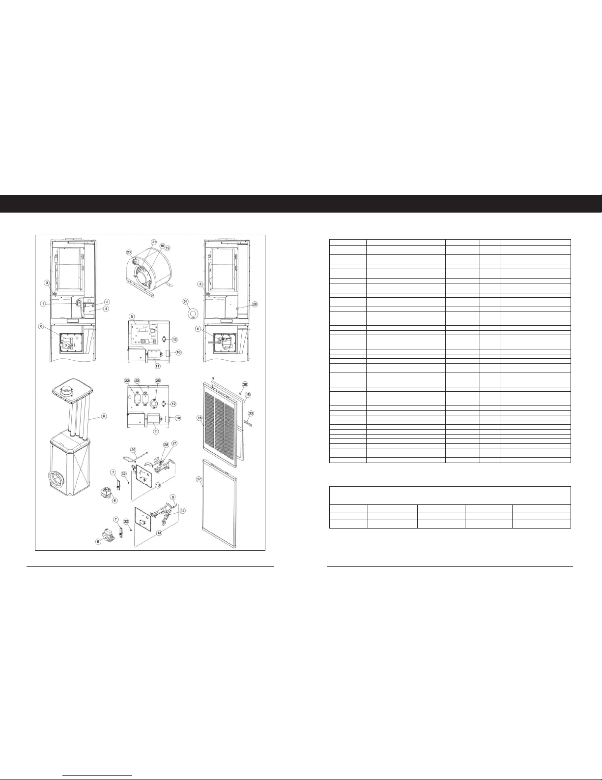
REPLACEMENT PARTS
BURNER ORIFICE CHART- (FACTORY INSTALLED)
MODEL 060 070 075 090
NAT GAS 72AG-144, #27 72AG-157, #22 72AG-166, #20 72AG-177, #16
LP GAS 72AG-089, #43 72AG-098, #40 72AG-101, #38 72AG-110, #35
ITEM NO.
1
2
3
4
5
6
7
8
9
10
11
12
13
14
15
16
17
18
19
20
21
22
23
25
26
27
28
29
30
31
32
33
USED ON FURNACE MODEL
G18D060, G18D075, G18D090
G17D090
G18D060, G18D075, G18D090
G17D090
All
G18D060, G18D075, G18D090
G17D090
G18D060, G18D075, G18D090
G18D060, G18D075, G18D090
G17D060, G17D070, G17D090
All
G17D060, G17D070, G18D060
G18D075, G18D090, G17D090
G18D060, G18D075, G18D090
All G18D
All G17D-w/H2/10 Blower
All G17D -w/A3/12 or A4/16 Blower
All
All
G17D060, G17D070
G17D090
G18D060, G18D075, G18D090
G18D060, G18D075, G18D090
All
All
All (Tall)
All (Short)
All G17D, G18D w/ H2/10 Blower
All G17D, G18D w/ A3/12 Blower
All G17D, G18D w/ A4/16 Blower
All w/ A4/16 Blower -3/4HP
All w/ H2/10 Blower-1/4HP
All w/ A3/12 Blower-1/3HP
All w/ A4/16 Blower-3/4HP
All
G17D models w/factory A/C blower
G17D090
All G17D
G17D060, G17D070
All G17D
All G17D
All G17D
All
G17D060
See Chart
All
PART NO
R68DD0010
R68DD0010
R71CA0006
R71CA0006
R68CA0005
R86GF0050
R86GF0050
R68GF0001
R68GF0006
R68GF0007
R68BKN007
R86GF0051
R86GF0052
R68GF0004
R68DD0009
R68DD0009
R68DD0008
R68GF0002
R68CA0004
R86GF0053
R86GF0054
R86GF0054
R68GF0005
R76AA0002
R86GF0055
R86GF0123
R86GF0119
R65GF0001
R65GF0002
R65GF0003
R86GF0056
R68DE0001
R68DE0002
R68DE0003
R69AB0001
R68AB0002
R68AB0002
R68CA0007
R68CA0006
R68GF0009
R68GF0008
R86GF0057
R86GF0058
R87NBF007
72AG-XXX
R87NNE001
QUAN
1
1
2 ft
2 ft
1
1
1
1
1
1
1
1
1
1
1
1
1
1
1
1
1
1
1
2
1
1
1
1
1
1
1
1
1
1
1
1
1
1
1
1
1
1
4
1
1
1
DESCRIPTION
Pressure Switch, -0.20 N.O.
Pressure Switch, -0.20 N.O.
Silicon Tubing
Silicon Tubing
Limit Switch, Manual, Upper-180F
Boost Blower Assembly, w/ air orifices
Boost Blower Assembly, w/air orifices
Integrated Control Board, HSI
Gas Valve-for HSI Electric Ignition
Gas Valve- for Standing Pilot Ignition
Valve Bracket & Orifice Holder
Heat Exchanger & Gaskets
Heat Exchanger & Gaskets
Flame Sensor
System Switch-SPST
System Switch-SPST
System Switch-SPDT
Tran sformer (115V-24V, 40VA)
Limit Switch- Open 140F-Close 110F
Burner Assembly
Burner Assembly
Burner Assembly
Hot Surface Igniter
Filter (16" x 20" x1")
Door Panel-Upper
Door Panel-Lower
Door Panel- Lower
Motor-1/4 HP
Motor-1/3 HP
Motor-3/4 HP
Motor Mount Assembly
Capacitor- 10/370V
Capacitor- 15/370V
Capacitor- 25/370V
Blower Wheel-10x8
A/C Blower Relay
Comb Boost Blower Relay
Fan Switch
Vent Limit- Manual Reset
Thermocouple
Pilot Burner
Pilot Tube
Door Latch,set
Combustion Air Orifice
Main Burner Orifice
Filter Retainer Bracket
 Loading...