

MORTEX G17D, G18D Installation Instructions Manual
1
Mortex Products, Inc. / FT. WORTH, TX 76106 G17 / G18 Installation Instructions Printed 04/04
16
Mortex Products, Inc. / FT. WORTH, TX 76106 G17 / G18 Installation Instructions Printed 04/04
SEALED COMBUSTION
DOWNFLOW
GAS FURNACE
FOR INSTALLATION IN: MANUFACTURED (MOBILE) HOMES,
RECREATIONAL VEHICLES, PARK MODELS, MODULAR HOMES AND
BUILDINGS
CAUTION: READ ALL SAFETY GUIDES
BEFORE INSTALLING THIS FURNACE
Contents Page
General Information . . . . . . . . . . . . . . . . . . . . . . . . . . . . . . . .1
Specifications . . . . . . . . . . . . . . . . . . . . . . . . . . . . . . . . . . . . .2
Safety Considerations . . . . . . . . . . . . . . . . . . . . . . . . . . . . . . .3
Installation Standards . . . . . . . . . . . . . . . . . . . . . . . . . . . . . . . .3
High Altitude Installation . . . . . . . . . . . . . . . . . . . . . . . . . . . . .3
Installation Clearances . . . . . . . . . . . . . . . . . . . . . . . . . . . . . . .3
Return Air . . . . . . . . . . . . . . . . . . . . . . . . . . . . . . . . . . . . . . .4-5
Alcove & Closet Installations . . . . . . . . . . . . . . . . . . . . . . . . . . .5
Air Distribution Systems . . . . . . . . . . . . . . . . . . . . . . . . . . . . .6
Duct Connector/Base . . . . . . . . . . . . . . . . . . . . . . . . . . . . . . . .6
Install Furnace . . . . . . . . . . . . . . . . . . . . . . . . . . . . . . . . . . . .7
Roof Jack Selection . . . . . . . . . . . . . . . . . . . . . . . . . . . . . . . . .7
Cut Openings & Install Roof Jack . . . . . . . . . . . . . . . . . . . . . . . .8
Installing in Snow Regions . . . . . . . . . . . . . . . . . . . . . . . . . . . .8
Roof Jack On Hi-Pitch Roof . . . . . . . . . . . . . . . . . . . . . . . . . . . .8
Transit-mode Roof Jack . . . . . . . . . . . . . . . . . . . . . . . . . . . . . .8-9
Connect Power Supply Wires . . . . . . . . . . . . . . . . . . . . . . . . . .9
Wall Thermostat . . . . . . . . . . . . . . . . . . . . . . . . . . . . . . . . . . .9
Connect Thermostat Wires . . . . . . . . . . . . . . . . . . . . . . . . . . . .9
Gas Piping . . . . . . . . . . . . . . . . . . . . . . . . . . . . . . . . . . . . . .9-10
Wiring Diagrams . . . . . . . . . . . . . . . . . . . . . . . . . . . . . . . . .11-13
Repair Parts List . . . . . . . . . . . . . . . . . . . . . . . . . . . . . . . . . .14-15
Final Procedure . . . . . . . . . . . . . . . . . . . . . . . . . . . . . . . . . . .16
Furnace and Air Conditioner Installations . . . . . . . . . . . . . . . . .16
High Altitude Deration Chart . . . . . . . . . . . . . . . . . . . . . . . . . .16
GENERAL INFORMATION
These downflow sealed combustion furnaces install in
Manufactured Homes, Recreational Vehicles or modular
construction. The furnaces conform to Part 3280 (a) (2) of HUD
Manufactured Home Construction and Safety Standards. They
must be installed only with listed RJ-Roof Jack, sealed
combustion venting system.
NOTE: These instructions are intended to assist qualified
individuals experienced in the installation of heating equipment.
Some state and local codes require installation personnel to be
licensed. Read all instructions before starting the installation.
SAVE THIS MANUAL
NOTICE - A furnace set-up and any adjustment needed is the
responsibility of the installer/retailer/contractor and is not
covered by the furnace manufacturers warranty.
CHECKLIST: FURNACE START-UP
1. Has furnace roof jack crown been correctly installed?
2. Has the furnace gas valve and burner orifice been correctly
converted to L.P. Gas where applicable?
3. Is the gas line outlet pressure set for the fuel used?
NAT Gas is 3.5” W.C. and L.P. Gas is 10.0”W.C.
4. If the home uses a crossover air connector duct, is it installed
per the homebuilders installation instruction?
5. Has the furnace been operated through a complete
heating cycle?
INSTALLATION INSTRUCTIONS
FINAL PROCEDURE
INSTALL FURNACE DOOR PANELS
A. Install the lower door panel by engaging 2 tabs on
bottom cabinet pan into slots on plastic end cap. Then,
push in top of door panel until clips on the center divider
panel are engaged with latches on door.
B. Install the upper louver door panel in a similar manner,
by first engaging tabs on the center divider and then
pushing the panel in to engage the clips at top of the
cabinet.
FINISH AND TRIM
The alcove or closet installation may be finished and
trimmed out as needed.
AIR CONDITIONING SYSTEMS
If an air conditioning system is installed which does not use
the blower for air distribution and operates completely
independent of the furnace, the thermostat system shall
include interlock, which prevents simultaneous operation of
the furnace and air conditioner. An interlock system
typically contains a switch, which must be turned to either
HEAT or COOL to activate either heating or cooling
operation. A cooling thermostat may include a positive OFF
switch for this purpose.
When used in connection with a cooling unit the furnace
shall be installed parallel with or on the upstream side of
the cooling unit to avoid condensation in the heat
exchanger. For installations with a parallel flow
arrangement, the furnace must be equipped with a damper
or other means to prevent cold air from being discharged
up around the heat exchanger.
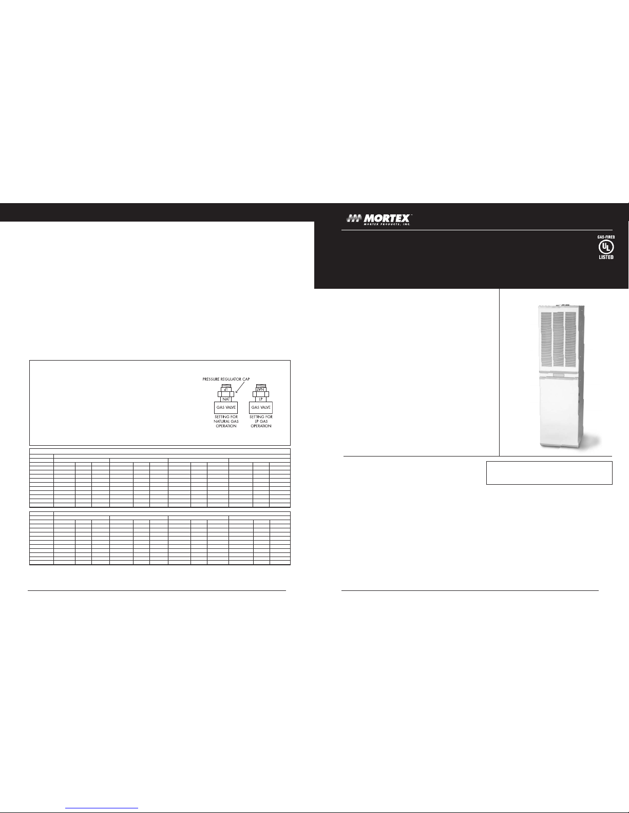
GAS VALVE CONVERSION INSTRUCTIONS
1. Follow instructions “TO TURN OFF GAS TO APPLIANCE”
2. Remove two bolts securing the gas valve bracket. Pull gas valve
valve bracket and burner orifice holder exposing the main burner orifice.
3. Install burner orifice specified on the rating plate for the desired gas.
Conversion parts are in a bag attached to the gas valve.
4. Replace valve, bracket/orifice holder, and bolts.
Attach ID tag for the desired gas adjacent to the gas valve.
Ensure that all connections are tight.
5. Unscrew and reverse the pressure regulating cap so the name of the
desired gas is closest to the valve. See illustration.
HIGH ALTITUDE DERATE CHART- MAIN BURNER ORIFICE SIZE
NATURAL GAS
ELEVATION 60,000 BTUH FURNACE 70,000 BTUH FURNACE 75,000 BTUH FURNACE 90,000 BTUH FURNACE
PART NO ORIF DIA. DRILL SIZE PART NO ORIF DIA. DRILL SIZE PART NO ORIF DIA. DRILL SIZE PART NO ORIF DIA. DRILL SIZE
SEA LEVEL 72AG-147 0.1470 26 72AG-159 0.1590 21 72AG-161 0.1610 20 72AG-180 0.1800 15
2,000 72AG-144 0.1440 27 72AG-154 0.1540 23 72AG-161 0.1610 20 72AG-177 0.1770 16
3,000 72AG-140 0.1405 28 72AG-154 0.1540 23 72AG-159 0.1590 21 72AG-173 0.1730 17
4,000 72AG-140 0.1405 28 72AG-152 0.1520 24 72AG-157 0.1570 22 72AG-173 0.1730 17
5,000 72AG-140 0.1405 28 72AG-149 0.1495 25 72AG-154 0.1540 23 72AG-169 0.1690 18
6,000 72AG-136 0.1360 29 72AG-147 0.1470 26 72AG-152 0.1520 24 72AG-166 0.1660 19
7,000 72AG-136 0.1360 29 72AG-144 0.1440 27 72AG-149 0.1490 25 72AG-161 0.1610 20
8,000 72AG-128 0.1285 30 72AG-140 0.1405 28 72AG-147 0.1470 26 72AG-161 0.1610 20
9,000 72AG-128 0.1285 30 72AG-140 0.1405 28 72AG-144 0.1440 27 72AG-157 0.1570 22
10,000 72AG-128 0.1285 30 72AG-136 0.1360 29 72AG-140 0.1405 28 72AG-152 0.1520 24
LP-PROPANE GAS
ELEVATION 60,000 BTUH FURNACE 70,000 BTUH FURNACE 75,000 BTUH FURNACE 90,000 BTUH FURNACE
PART NO ORIF DIA. DRILL SIZE PART NO ORIF DIA. DRILL SIZE PART NO ORIF DIA. DRILL SIZE PART NO ORIF DIA. DRILL SIZE
SEA LEVEL 72AG-089 0.0890 43 72AG-099 0.0995 39 72AG-101 0.1015 38 72AG-113 0.1130 33
2,000 72AG-086 0.0860 44 72AG-098 0.0980 40 72AG-099 0.0995 39 72AG-110 0.1100 35
3,000 72AG-086 0.0860 44 72AG-096 0.0960 41 72AG-098 0.0980 40 72AG-110 0.1100 35
4,000 72AG-086 0.0860 44 72AG-096 0.0960 41 72AG-096 0.0960 41 72AG-106 0.1065 36
5,000 72AG-082 0.0820 45 72AG-093 0.0930 42 72AG-096 0.0960 41 72AG-106 0.1065 36
6,000 72AG-082 0.0820 45 72AG-093 0.0930 42 72AG-093 0.0930 42 72AG-104 0.1040 37
7,000 72AG-081 0.0810 46 72AG-089 0.0890 43 72AG-093 0.0930 42 72AG-101 0.1015 38
8,000 72AG-078 0.0780 47 72AG-089 0.0890 43 72AG-089 0.0890 43 72AG-101 0.1015 38
9,000 72AG-078 0.0780 47 72AG-086 0.0860 44 72AG-089 0.0890 43 72AG-098 0.0980 40
10,000 72AG-076 0.0760 48 72AG-086 0.0860 44 72AG-086 0.0860 44 72AG-096 0.0960 41
Reference: NFPA No. 54, ANSI Z 223.1 National Fuel Gas Code
Table shows 4% Input Reduction per 1,000 feet elevation.
For Canadian High Altitude (2,000-4,500 feet), reduce gas pressure to burner manifold (manifold Ps.) to 3.0" W.C., and 9.0" W.C. for LP (Propane) Gas
G17D, G18D
Sizes 060-090
WARNING-RISK OF FIRE OF ELECTRICAL SHOCK
Only qualified service personnel shall be used to install
and provide maintenance of this furnace.
P/N: 61GF0011
3
Mortex Products, Inc. / FT. WORTH, TX 76106 G17 / G18 Installation Instructions Printed 04/04
2
Mortex Products, Inc. / FT. WORTH, TX 76106 G17 / G18 Installation Instructions Printed 04/04
INSTALLATION INSTRUCTIONS
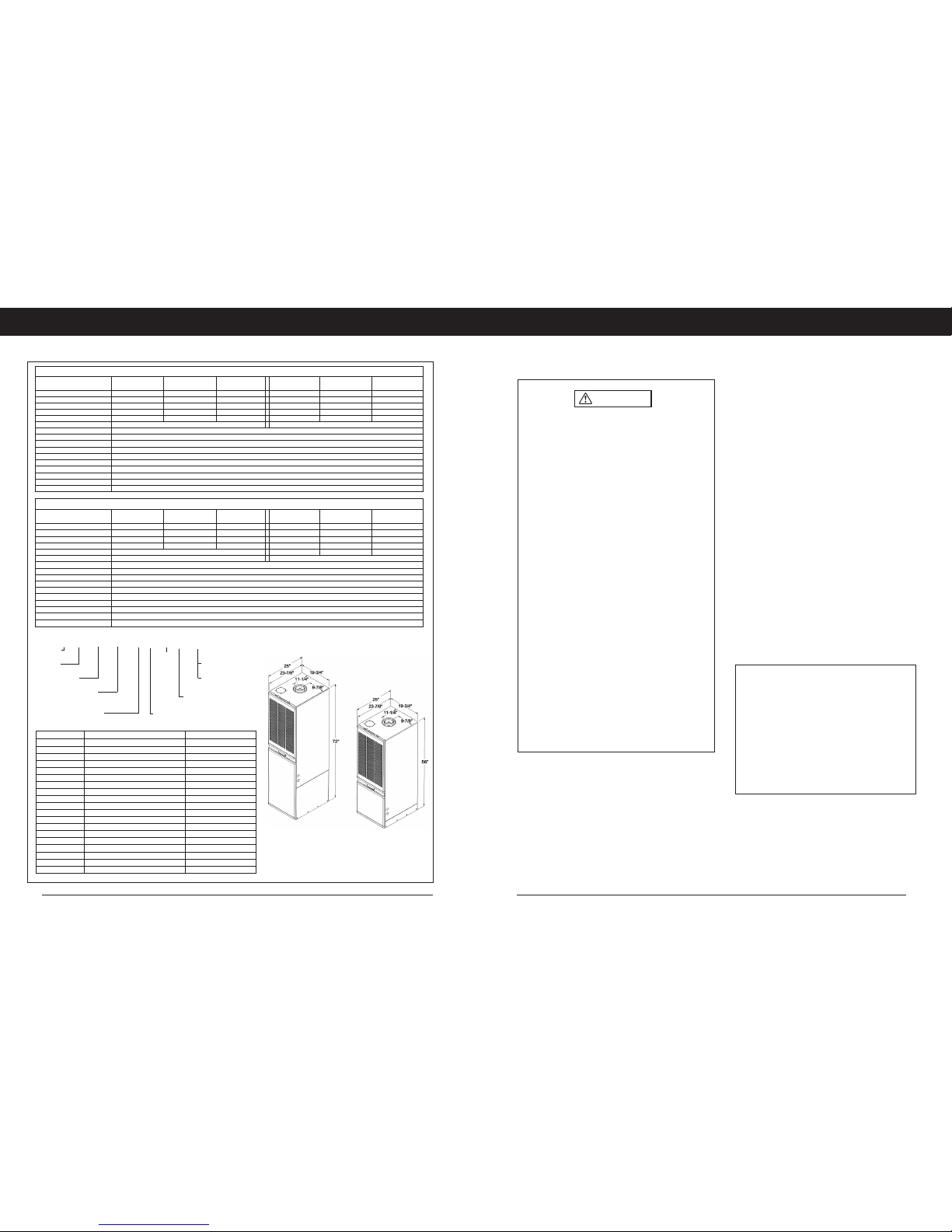
SPECIFICATIONS
“B” Cabinet “A” Cabinet
CAUTION
• ELECTRIC POWER - turn off all electrical power to
furnace before performing any maintenance or
service on unit. Failure to take this precaution may
result in personal injury due to electrical shock.
•
SERVICE - a qualified service technician should
service this unit. Fuel burning appliances can
generate toxic flue products. Modification of the
appliance can cause carbon monoxide in deadly
amounts. To prevent a safety hazard, maintain this
appliance in a safe operating manner and do not
modify.
•
DO NOT modify vent or operate the unit with a
blocked vent or inlet air pipe.
•
DO NOT re-drill a burner orifice. If the orifice size
must be changed, use only a new orifice.
•
DO NOT use matches, lighters, candles, or other
sources of open flame to check for gas leaks.
•
PROPER maintenance for this unit requires certain
mechanical skills and tools. If you are at all
uncertain, contact your Heating Service Co. for
maintenance and service.
•
CONSULT with a service technician for any
problems or questions you may have pertaining to
this appliance.
•
ALWAYS inspect the appliance before starting a
new heating season, paying special attention to vent
pipes and fuel lines.
SAFETY CONSIDERATIONS
NOTE: The words “Shall” or “Must” indicate a
requirement, which is essential to satisfactory and safe
furnace performance.
The words “Should or “May” indicate a recommendation
which may be helpful or enhance performance.
INSTALLATION STANDARDS
CODE COMPLIANCE
The installer shall become familiar with and follow all local
codes and regulations which govern the installation of this
furnace. Where applicable, local codes may take
precedence.
• Federal Manufactured Home Construction and Safety
Standards – HUD Title 24, Part 3280.
• National Fuel Gas Code – ANSI-Z223.1/NFPA-54
• Unit electrical wiring and grounding shall comply with
National Electrical Code – ANSI/NFPA-70.
• “Manufactured Housing” – NFPA-501 and “Fire Safety
Criteria for Mobile Home Installations – NFPA 501A.
• “Recreational Vehicles” – ANSI-119-2/NFPA-501C
HIGH ALTITUDE INSTALLATION
For elevation above 2,000 feet derate furnace input 4% for
each 1,000 feet of elevation above sea level. Furnace
deration is accomplished by reducing the burner orifice
size. See DERATING CHART for orifice size and
CONVERSION INSTRUCTIONS, Page16.
INSTALLATION CLEARANCES
These furnaces are design certified for the following
minimum clearances from combustible materials in alcove
or closet installations.
Locate furnace to ensure adequate room for service access
to all vent connections, controls and the heat exchanger. A
front clearance of 18” minimum (24” recommended) shall
be provided by a closet door or spacing away from a
facing wall or partition.
For installation on combustible flooring (except carpeting)
using manufacturers supplied floor base P/N 87FB0005
and duct connector Series P/N 86AA001-.
Top . . . . . . . . . . . . . . . . . . . . . . . . . . .6 in.
Sides . . . . . . . . . . . . . . . . . . . . . . . . . .0 in.*
Back . . . . . . . . . . . . . . . . . . . . . . . . . .0 in *
Alcove-front of furnace . . . . . . . . . . . . .18 in
Closet- front of furnace . . . . . . . . . . . . . .6 in**
Duct . . . . . . . . . . . . . . . . . . . . . . . . . . .0 in.
Vent/Roof Jack . . . . . . . . . . . . . . . . . . .0 in.
* If the return air opening is below the top of
the furnace, clearance to the side or rear shall
be 6”.
** See Return Air for clearances less than 6”.
PART NO. DESCRIPTION NOTES
90-RJF1729-AL Body, Roof Jack, Gas-FLAT Height 'A'- 73 in.- 85 in.
90-RJF2551-AL Body, Roof Jack, Gas-FLAT Height 'A'- 81 in. - 107 in.
90-RJS1729-AL Body, Roof Jack, Gas-SLOPE 3/12 Height 'B'- 81 in. - 101 in.
90-RJS2551-AL Body, Roof Jack, Gas-SLOPE 3/12 Height 'B'- 97 in. - 123 in.
90-RJS3868-AL Body, Roof Jack, Gas-SLOPE 3/12 Height 'B'- 110 in. - 140 in.
90-RJS6399-AL Body, Roof Jack, Gas-SLOPE 3/12 Height 'B'- 135 in.- 171 in.
90-RJCRWN-AL Crown, Roof Jack, Gas Use w/ Gas Roof Jack Body
90-TRM-RNG Ceiling Trim Ring, Roof Jack Trim out to inside RJ- pipe
90-RJTRC Kit, Transit- Roof Jack--Cap & Labels for transport-remove on site
90-OUTXT16-AL Roof Jack Outdoor Extension-Gas 16" Extend pipes/crown-16 in.
90-INSXT10-AL Roof Jack Inside Extension-Gas 10" Extend inside pipes-10 in.
90-RJS56 5-6/12 Slope, Roof Saddle Adapter Add to RJS 3/12 Roof Jack
90-DCUO-OI 86AA0013 Duct Conn + 87FB0005 Flr Base Floor to Duct- 1 in.-4 in.
90-DCUO-O2 86AA0014 Duct Conn + 87FB0005 Flr Base Floor to Duct- 6 in.-8 in.*STD
90-DCUO-O3 86AA0015 Duct Conn + 87FB0005 Flr Base Floor to Duct- 8 in.-12 in.
90-CABEXT4 White, Top, Cabinet Extender Plate Fill alcove 76" top opening
90-BLWRELAY Blower Relay/Wiring Kit Convert Furn for A/C
87-1008-3/12A1 A/C Blower, 3 Speed-1/3 HP 2-4 Ton A/C
87-1008-4/16A1 A/C Blower, 4 Speed-3/4 HP 2-5 Ton A/C
PRODUCT CODE
ACCESSORIES
G1 8D075 B - A 3/12
G=GAS NOM CFM-HI SPEED, W/COIL
DASH @ 0.3" W.C Ext SP (DUCT)
1=SERIES 10-1010, 12-1180, 16-1620
7=75, 8=80 AFUE 1,2,3,4- MOTOR SPEEDS
D=DNFLO, MANUFTR-MOD A=A/C BLOWER & RELAY
H=HEAT or 3T BLW READY, NO RELAY
060,070,075,090 BTUH INPUT A=56", B=72" TALL FURN CABINET
80 AFUE- AUTOMATIC HOT SURFACE IGNITION
Model No. G18D060A-H2/10 G18D075A-H2/10 G18D090A-H2/10 G18D060B-A3/12 G18D075B-A3/12 G18D090B-A3/12
Input, BTUH 60,000 75,000 90,000 60,000 75,000 90,000
Output, BTUH 48,000 61,000 72,000 48,000 61,000 72,000
AFUE, % 80.0 81.0 80.0 80.0 81.0 80.0
With A-Coil Cabinet NO NO NO YES YES YES
Ignition Type Auto-Elect Auto-Elect Auto-Elect Auto-Elect Auto-Elect Auto-Elect
Air Temperature Rise, Range-F 40-70 45-75 50-80 40-70 45-75 50-80
Blower-Heat or Heat/Cool Heat Heat/Cool -4T
Designed Max Outlet Air Temp-F 165
Max. External SP (Duct), In. W.C. 0.30
Factory Equipped Fuel Natural Gas
High Altitude For elevations above 2,000 feet, reduce input 4% for each 1,000 ft. elevation above sea level
Furnace Flue Pipe Must Use RJS or RJF Roof Jack
Gas Connection 1/2" NFPT
Electric Service 120VAC, 60Hz, 1 Ph
Fuse or Circuit Breaker 15 Amp
Thermostat Circuit 24VAC, 60Hz, 40VA
Filters 2-16"x20"x1"
75 AFUE- STANDING PILOT IGNITION NOTE: Blower Drives- H2/10, A3/12 , A4/16 listed with all G17D-G18D furnace models.
Model No. G17D060B-H2/10 G17D070B-H2/10 G17D090B-H2/10 G17D060B-A3/12 G17D070B-A3/12 G17D090B-A3/12
Input, BTUH 60,000 70,000 90,000 60,000 70,000 90,000
Output, BTUH 48,000 55,000 71,000 48,000 55,000 71,000
AFUE, % 76.0 75.0 76.0 76.0 75.0 76.0
With A-Coil Cabinet YES YES YES YES YES YES
Ignition Type Pilot Pilot Pilot Pilot Pilot Pilot
Air Temperature Rise, Range-F 45-75 45-75 50-80 45-75 45-75 50-80
Blower-Heat or Heat/Cool Heat/3T Blower Ready, No AC Controls Heat/Cool -4T
Designed Max Outlet Air Temp-F 165
Max. External SP (Duct), In. W.C. 0.30
Factory Equipped Fuel Natural Gas
High Altitude For elevations above 2,000 feet, reduce input 4% for each 1,000 ft. elevation above sea level
Furnace Flue Pipe Must Use RJS or RJF Roof Jack
Gas Connection 1/2" NFPT
Electric Service 120VAC, 60Hz, 1 Ph
Fuse or Circuit Breaker 15 Amp
Thermostat Circuit 24VAC, 60Hz, 40VA
Filters 2-16"x20"x1"
5
Mortex Products, Inc. / FT. WORTH, TX 76106 G17 / G18 Installation Instructions Printed 04/04
4
Mortex Products, Inc. / FT. WORTH, TX 76106 G17 / G18 Installation Instructions Printed 04/04
INSTALLATION INSTRUCTIONS
RETURN AIR
ALCOVE INSTALLATION
The furnace may be installed free standing or in an alcove
with a free flow of air back to the furnace. A minimum of
18” shall be provided at the front for return air and service
access.
CLOSET INSTALLATION - 6 in.
NOTE: If return air is through a side wall, there must be a
minimum of 6-in. clearance from side wall to furnace in
addition to 6-in. minimum clearance from inside of closet
door to front of furnace.
If a louvered door complying with the minimum air requirements is used, the front clearance may be reduced to 1”.
CLOSET INSTALLATIONS
Additional Requirements
Concerning under floor or ceiling return air systems, the
following items (1-10) must be adhered to:
1. The return-air opening into the closet, regardless of
location, is to be sized not less than specified on the
appliance rating plate.
2. If the return-air opening is located in the floor of the
closet (versus the vertical front or side wall), the
opening is to be provided with means to prevent its
inadvertent closure by a flat object placed over the
opening.
3. The cross-sectional area of the return duct system
(when located in the floor or ceiling of the
manufactured home) leading into the closet is to be not
less than that of the opening specified on the appliances rating plate.
4. The total free area of openings in the floor or ceiling
registers serving the return-air duct system is to be not
less than 150% of the size opening specified on the
appliance rating plate. At least one such register is to
be located where the likelihood of its being covered by
carpeting, boxes, and other objects is minimized.
5. Materials located in the return duct system have a
flame spread classification of 200 or less.
6. Non-combustible pans having one-inch upturned
flanges are located beneath openings in the floor
return duct system.
7. Wiring materials located in the return duct system
conform to Article 300-22 (B&C) of the National
Electric Code, ANSI / NFPA-70.
8. Gas piping is not run in or through the return duct
system.
9. The negative pressure in the closet, as determined
by test with the air-circulating fan operating at high
heating speed and the closet door closed, is to be not
more negative than minus 0.05-inch water column.
10. For floor return systems, the manufactured home
manufacturer or installer shall affix a prominent
warning where it is easily read when the closet door is
open.
The marking shall read:
HAZARD OF ASPHYXIATION
DO NOT COVER OR RESTRICT FLOOR
OPENING, or equivalent
WARNING
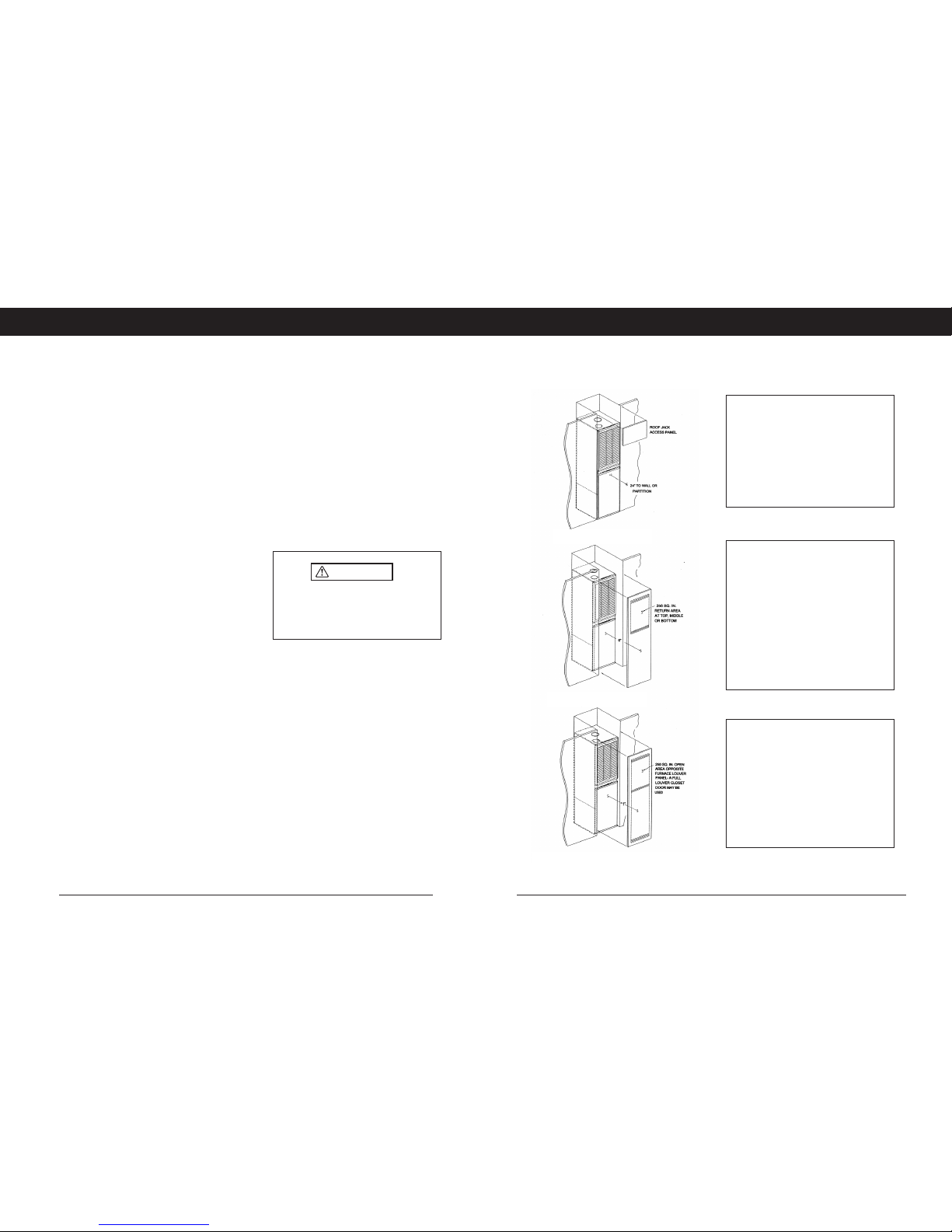
RETURN AIR
ALCOVE
A minimum of 18” front clearance to a facing
wall or partition is needed for service access
and return air.
Provide a removable panel above the furnace
for access to roof jack and pipe connections on
top of the furnace.
CLOSET - 6” CLEARANCE
A minimum of 250 sq. in free open area return
opening is required to the closet. The return
opening may be anywhere on or above the
closet door. If the return is through a side wall,
and the opening is below the top of the furnace,
a minimum of 6-in. clearance from side wall to
furnace must be provided in addition to 6-in
minimum clearance from inside of closet door to
furnace.
If a 5T A/C will be installed, the return shall be
increased to 390-sq. in. open area.
SPECIAL-CLOSET, 1” CLEARANCE
For closet installations with less than 6-in.
clearance from inside of closet door to furnace,
a louvered closet door must be used with a min.
of 250 sq. in open area directly in line with the
furnace top louver panel as shown. A fully
louvered closet door may be used.
If a 5T A/C will be installed, the return shall be
increased to 390 sq. in open area directly in
line with the furnace louver panel.
ALCOVE INSTALLATION
CLOSET INSTALLATION
*SPECIAL - 1”- 6” CLOSET INSTALLATION
 Loading...