

MORTEX G17, G18 Owner's Manual
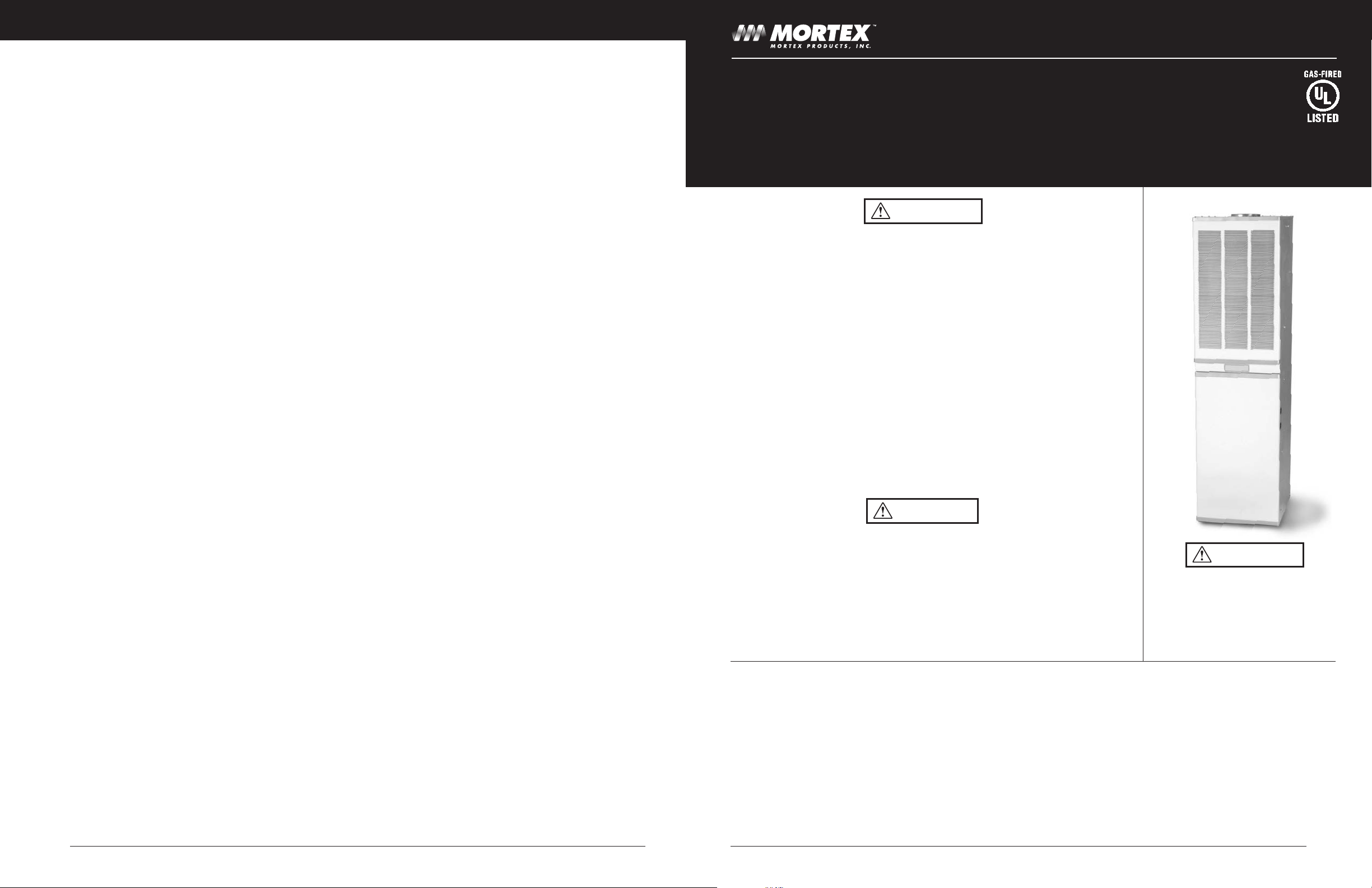
SEALED COMBUSTION
DOWNFLOW
GAS FURNACE
This heavy duty furnace will provide you with reliable and efficient operation if maintained. Please read the entire
booklet. It contains information on furnace operation and maintenance needed to keep it operating safely and
efficiently. Thank you for choosing our product.
Keep this manual for future reference
FOR YOUR SAFETY – Do not store or use gasoline or other flammable vapors and liquids
in the vicinity of this or any other appliance.
Improper installation, adjustment, alteration, service or maintenance can cause injury or property damage. Refer to this manual. For assistance or additional information consult a qualified
installer, service agency or the gas supplier.
FOR YOUR SAFETY- WHAT TO DO IF YOU SMELL GAS
• Do not try to light any appliance.
• Do not touch any electrical switch; do not use any phone in your building.
• Immediately call your gas supplier from a neighbors phone. Follow the gas suppliers
instructions.
• If you cannot reach your gas supplier, call the fire department.
Never attempt to modify this furnace. Fire, explosion, or asphyxiation may result. If
malfunction occurs, obtain the assistance of a qualified service agent.
If not installed, operated, and maintained in accordance with the manufacturer’s
instructions, this product could expose you to substances in fuel or from fuel combustion which
are known to the State of California to cause cancer, birth defects or other
reproductive harm.
Use of furnace or air conditioning components that are not included in the Underwriters
Laboratories certification of this appliance may create a hazard, will invalidate the
certification, and will in many states make installation illegal. UL listed air conditioning
components are specified on the furnace label.
Before placing furnace in service, it must be checked to ensure it is equipped for the type of
gas being used. Failure to observe this caution may result in unsafe operation, explosion,
and/or fire or asphyxiation. Use of other components not tested in combination with this
furnace may make the equipment in violation of State Codes, may create a hazard, and may
ruin the equipment.
IMPORTANT:
If your home is located at an elevation above 2,000 feet, the gas input to the furnace should be derated (reduced). The dealer or the Gas
Company may already have applied the necessary deration to the furnace burner. They will be able to advise you if this is the case. If not,
the deration of the burner should be accomplished only by a qualified service company or the Gas Company. Deration will insure continued
use of the unit; failure to derate properly may create a hazard and will eventually render the unit inoperable.
This furnace was shipped from the factory with a gas burner orifice installed for Natural gas. If the furnace will be operating on LP gas, the
furnace burner orifice must be converted. The LP gas orifice for conversion is stored in a bag on the gas valve. It is the correct size for
operation to 2,000 feet. If the furnace will be operating on LP gas above 2,000 feet, the orifice supplied is too large to allow proper
operation. Contact your gas supplier for help to have the proper size derated orifice installed. Note: Deration of the unit is not covered by
the manufacturers warranty. This procedure is considered a part of the installation process and required to make the furnace operate properly.
Do not use this appliance if any part
has been under water. Immediately call
a qualified service technician to inspect
the appliance and to replace any gas
control which has been under water.
OWNER’S MANUAL
WARNING
WARNING
CAUTION
14
Mortex Products, Inc. / FT. WORTH, TX 76106 G17 / G18 Owner’s Manual Printed 04/04Mortex Products, Inc. / FT. WORTH, TX 76106 G17 / G18 Owner’s Manual Printed 04/04
will lock out. It will remain in lock out for one hour, at which
time the furnace will try for ignition again.
7. About 60-90 seconds after the burner lights, the furnace
blower will run.
8. When the thermostat is satisfied, the electrical circuit to the
control board is opened. At the same time the circuit to the
combustion blower and the gas valve is opened and the
burner flame will be extinguished.
The control board keeps the furnace blower running for 1-2
minutes to allow additional heat to be drawn from the heat
exchanger.
OBSERVING BURNER OPERATION
1. Observe burner to make sure it ignites and to observe the
flame color. With Natural gas, the flame will be blue with
yellow tips; with Propane gas, a yellow flame can be expected.
2. Allow furnace to heat up until the blower cycles on. (2-1/2 min.)
3. Turn wall thermostat down.
4. Observe main burner flame to make sure it shuts off.
5. Let furnace cool and blower turns off.
6. If any abnormalities should occur, such as the burner failing to
light or to turn off, the flame looks sooty or it seems to be
“floating” around inside the heat exchanger, call a qualified
service technician for service.
IF FURNACE FAILS TO OPERATE PROPERLY
1. Check setting of the wall thermostat and position of the
heat/cool switch if air conditioning is installed.
2. Check to see that electrical power is “ON”.
3. Check to see that lever on gas valve is in the “ON” position.
4. Make sure that air filters are clean, supply registers are open
and return air grilles are not obstructed.
5. Be sure that furnace flue and inlet air pipes are open and
unobstructed.
6. On Automatic Ignition furnaces only, observe the Diagnostic
Light. This light is visible through a slot on the control panel
cover and flashes when there is a service problem. The
diagnostic codes are:
Steady On: Normal Operation
One Flash: Ignition Failure
Two Flashes: Pressure switch failed closed.
Three Flashes: Limit switch open.
Five Flashes: Gas valve energized with no call for heat
Six or Rapid Flash: Reversed polarity.
If the cause for failure to operate properly is not obvious, call a
service technician or your gas supplier.
THE FURNACE CONTROLS AND THEIR FUNCTION
• Auto Ignition & Standing Pilot Units with “ONOFF” System Switch
- The switch is on the right side of the
furnace control box and turns electrical power to the furnace
on or off. It must be “ON” for the furnace to operate.
•
Standing Pilot, Heat Model with “ON-OFF-FAN”
System Switch
-The switch turns electrical power to the
furnace on or off. The switch must be set to “ON” for the
furnace to operate. To run the blower continuously without
heating, set the switch to “FAN”.
•
Limit Switch - All furnace models are protected by two (2)
temperature limit safety switches. The lower limit switch (inside
furnace control box) is an automatic reset type. The limit switch
by the furnace blower is a manual reset type.
•
Vent Limit Switch - Standing Pilot furnaces without a
combustion blower are additionally protected by a manual
reset safety switch located on the vertical combustion air inlet pipe.
•
Fan Switch - Standing Pilot furnaces have a temperature
sensing device that turns on the blower when sufficient heat
has built up inside the furnace. During warm weather, the
blower may come on periodically or operate continuously due
to heat from the pilot and the warm weather. -This is normal. If
blower operation is not desired during this time, the “ON-OFFFAN” switch may be set in the “OFF” position to cut electrical
power to the furnace.
•
Gas Valve - The gas valves for all models are 100% shut-off
type and will fail safe if, for some reason, the gas is turned off .
INSPECTION AND MAINTENANCE BY THE HOMEOWNER
•Make a visual inspection of the furnace every 30 days. Do the
following:
•
Filters - Clean filters at least every (3) months and replace as
needed. Size; 16”x20”x1”
•
Motor Lubrication - None: The combustion and air
circulator motors are permanently lubricated.
•
Return Air - On some closet installations, the return air opening
may be in the floor. DO NOT cover or obstruct these floor
openings or any other return air opening to the closet.
•
Heat Exchanger - under normal conditions, no cleaning is
needed. If cleaning becomes necessary, only a service
technician should do so. Chemicals should not be used to
clean the heat exchanger.
•
Furnace Vestibule - periodically remove furnace panels
and clean the vestibule area to remove dust and lint. Shut off
all electrical power to the unit before cleaning.
•
When you’re away - the furnace has safety controls to
shut the unit down if there is a malfunction. Therefore do not
assume it can operate unattended for prolonged time
periods. If there is a damage possibility to your home due to
freezing weather, have a neighbor check your home daily.
INSPECTION AND MAINTENANCE BY A SERVICE TECHNICIAN
Annual furnace maintenance and inspection is recommended.
• Replace air filters, and clean dust and lint from furnace and
area.
• Remove blower assembly and clean blower wheel and motor.
•Inspect the combustion chamber, flue collar and roof jack.
• Check the gas valve and gas line connections for leaks.
•Make adjustments as needed for good operation.
SEASONAL SERVICE INFORMATION
In regions where there is heavy snow accumulation, a roof jack crown
extension is recommended to prevent blockage of the roof jack
combustion air openings.
During extreme cold weather, ice may form on the furnace roof jack.
Small amounts of ice on the roof jack will present no problem to proper furnace operation. Excessive ice formation could restrict the combustion air supply to the burner causing inefficient burner operation. If
excessive ice has formed on the inlet or exhaust portions of the
roof jack, it must be carefully removed.
OWNER’S MANUAL
P/N : 61GF0010
32
Mortex Products, Inc. / FT. WORTH, TX 76106 G17 / G18 Owner’s Manual Printed 04/04Mortex Products, Inc. / FT. WORTH, TX 76106 G17 / G18 Owner’s Manual Printed 04/04
WARRANTY AND OWNERS RESPONSIBILITIES
The furnace manufacturer warrants the furnace to be free from defects
in material or workmanship for the time period stated in the warranty.
The home owner has the sole responsibility to make certain the gas
furnace has been correctly set up and converted to use the proper fuel
(LP or Natural Gas) and adjusted to operate properly.
The furnace manufacturer is not responsible for any repair costs to
correct problems due to improper setup, improper installation, furnace
control damage at installation, furnace adjustment, improper operating
procedure by the user, etc.
Some specific examples of parts or service charges incurred not
covered by the furnace manufacturers warranty are:
a) Cracked gas valve body due to over tightening at installation.
b) Converting the furnace to use another type of gas.
c) Correcting problems caused by improper gas supply pressure
to the furnace.
d) Furnace problems due to faulty installation of the furnace
venting system (roof jack).
e) Addition of a roof jack extension due to unusual wind
conditions or snow conditions.
f) Adjustments to furnace or wall thermostat.
Gas Supply
The gas supply to the home will be either Natural or Propane gas. The
furnace is factory equipped to operate on one of these gases. A tag
adjacent to the furnace gas valve specifies the type of gas your furnace
is equipped to use.
If gas to the home is different from that specified on the tag, the
furnace can be converted by following instructions on the furnace
Safety Label. Conversion parts are in the small bag attached to the
gas control valve. Make sure the proper size gas orifice is used.
The orifice size is printed on the furnace model-data label.
Natural Gas Operation
The furnace is designed for 7” WC inlet gas pressure. Pressure is
reduced to 3.5” WC by the pressure regulator in the gas valve.
LP-Propane Gas Operation
The furnace is designed for 11” WC inlet gas pressure. Pressure is
reduced to 10.0” WC by the pressure regulator in the gas valve.
SAFETY INFORMATION
For your safety, read before lighting.
The first lighting of the furnace after any home setup must be
performed by a qualified service technician.
A. If this furnace has a pilot, it must be lighted by hand. When
lighting the pilot, follow the LIGHTING INSTRUCTIONS FOR
STANDING PILOT FURNACE exactly. If this furnace does not
have a pilot, it is lighted with an ignition device which
automatically lights the burner. Do NOT try to light the burner
by hand. Follow the LIGHTING INSTRUCTIONS FOR
AUTOMATIC IGNITION FURNACE.
B. BEFORE LIGHTING, smell all around the furnace for gas.
Smell next to the floor because some gas is heavier than air
and will settle to the floor.
WHAT TO DO IF YOU SMELL GAS:
• Do not try to light any appliance.
• Do not touch any electric switch and
• Do not use any phone in your building.
• Immediately call your gas supplier from a neighbor’s phone.
Follow the gas supplier’s instructions. If you cannot reach
your gas supplier, call the fire department.
C. Use only your hand to move the gas lever. NEVER USE
TOOLS. If the lever will not move by hand, don’t try to repair
it. Call a service technician. Force or attempted repair may
result in a fire or explosion.
D. Do not use this furnace if any part has been under water.
Immediately call a qualified service technician to inspect the
furnace and to replace any part of the control system and any
gas control which has been under water.
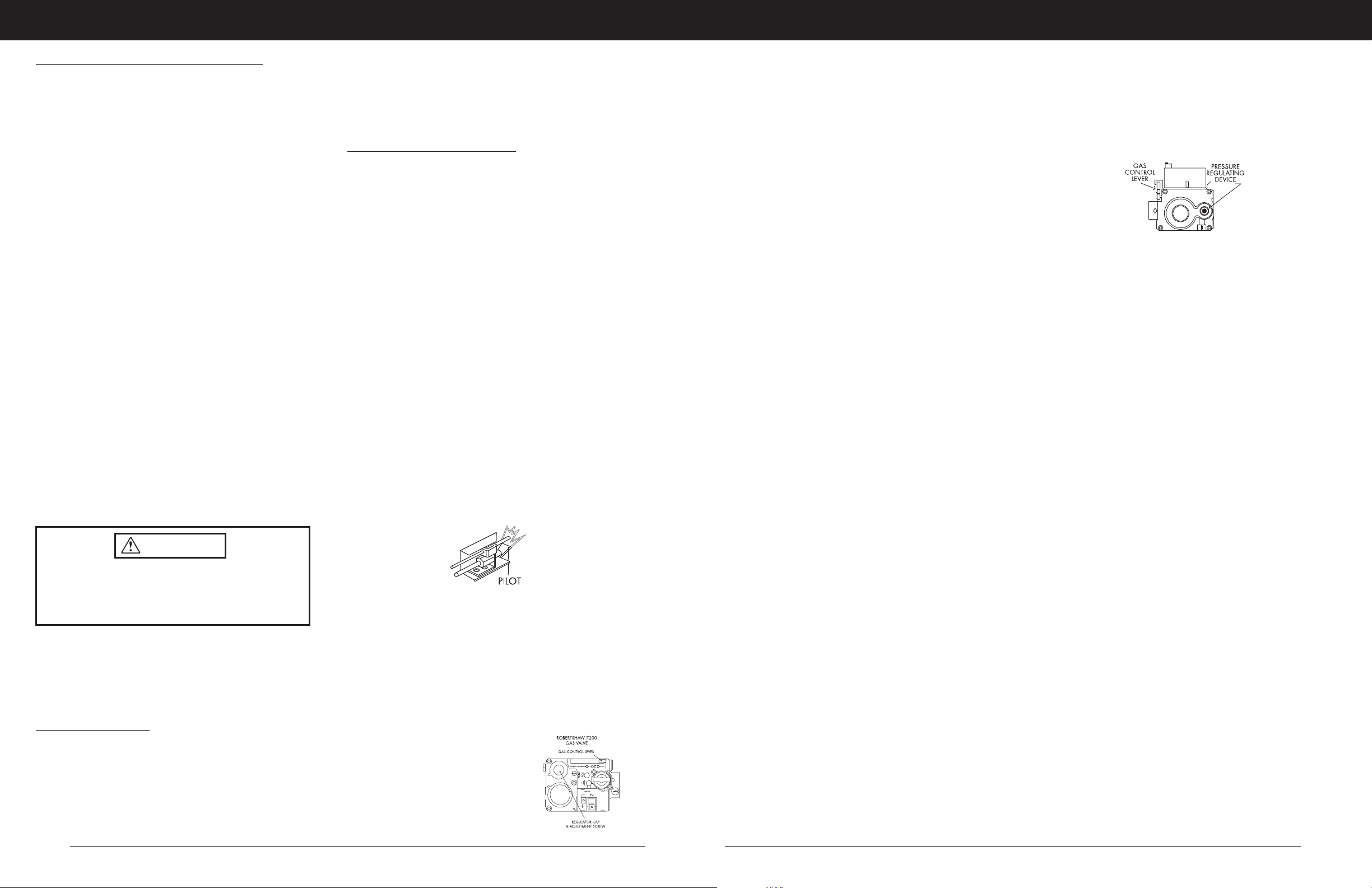
Lighting Instructions for Standing Pilot Furnace
1. STOP! Read the safety information.
2. Set the thermostat to lowest setting.
3. Turn off all electric power to the furnace.
4. Remove control access panels.
5. Move gas control lever to "OFF" position. Do not force. Turn
system switch on control panel to "OFF" position.
6. Wait (5) minutes to clear out any gas. Then smell for gas
including near the floor. If you smell gas, STOP! Follow "B"
in the safety information in this manual. If you don't smell
gas, go to the next step.
7. Locate the hinged pilot access door. Find pilot, follow metal
tube from gas control. The pilot is located inside the burner
compartment-adjacent to the main burner.
8. Move gas control lever to the "SET" position and hold.
Insert match in wire holder and immediately light the pilot.
Continue to hold the gas control lever for about one (1)
minute after the pilot is lit. Release lever and it will return to
the pilot position. Pilot should remain lit. If pilot goes out,
repeat steps 5 thru 8. If lever does not release or if the pilot
will not stay lit after several tries, move the gas control lever
to "OFF" and call your service technician or gas supplier.
9. Move gas control lever to "ON" position. Turn system switch
to "ON" position.
10. Replace control access panels.
11. Turn on all electric power to the furnace.
12. Set thermostat to desired setting.
FIG.1 STANDING PILOT GAS VALVE
SEQUENCE OF OPERATION
Standing Pilot- no Combustion Blower
1. On a call for heat, the thermostat contacts close supplying
24VAC to the gas valve.
2. When the gas valve is energized it initially opens at a reduced
flow and opens fully about 30 seconds later.
3. About 1-2 minutes after the burner lights, the furnace air
circulator blower comes on.
4. When the call for heat is satisfied, the thermostat contacts open
and the gas valve shuts off the gas flow.
5. After the burner shuts off, the blower continues to run for 2-4
minutes until the furnace has cooled.
SEQUENCE OF OPERATION:
Standing Pilot-with Combustion Blower
1. On a call for heat, the thermostat contacts close and supply
24VAC to a relay.
2. The relay contacts close and energize the 120V combustion
blower motor.
3. The inlet vacuum pressure from the combustion blower closes a
set of contacts in the air pressure switch energizing the 24VAC
gas control valve.
4. When the gas valve is energized it initially opens at a reduced
flow and opens fully about 30 seconds later.
5. About 1-2 minutes after the burner lights, the furnace air
circulator blower comes on.
6. When the call for heat is satisfied, the thermostat contacts
open, the gas valve shuts off gas flow and the combustion
blower stops.
7. After the burner shuts off, the blower continues to run for 2-4
minutes, until the furnace has cooled.
TO TURN OFF GAS TO FURNACE
Standing Pilot Models
1. Set thermostat to the lowest setting.
2. Turn off all electric power to the unit if service is to be performed.
3. Remove control access panels.
4. Move gas control lever to "OFF" position. DO NOT FORCE
5. Replace control access panels.
LIGHTING INSTRUCTIONS FOR
AUTOMATIC IGNITION FURNACE
1. STOP! Read the safety information on this label.
2. Set the thermostat to lowest setting.
3. Turn off all electric power to the appliance.
4. This appliance is equipped with an ignition device which
automatically lights the burner. Do not try to light the burner by
hand.
5. Remove control access panels.
6. Push in gas control knob slightly. Valve will snap to "OFF"
position.
7. Turn system switch to "OFF" position.
8. Wait (5) minutes to clear out any gas. If you smell gas, STOP!
Follow "B" in the safety information on this label. If you don't
smell gas, go to the next step.
9. Turn gas control knob to "ON" position. Set system switch to
"ON" position.
10. Turn on all electric power to the appliance.
11. Set thermostat to desired setting. Appliance will automatically
begin an ignition sequence which may take up to 60 seconds
before burner ignition is initiated.
12. After three (3) trials for ignition, if the furnace will not operate,
follow the instructions, "TO TURN OFF GAS TO APPLIANCE" and
call your service technician or gas supplier.
13. Replace control access panels.
FIG. 2 AUTO IGNITION GAS VALVE
TO TURN OFF GAS TO FURNACE
Automatic Ignition Models
1. Set thermostat to the lowest setting.
2. Turn off all electric power to the appliance if service is to be
performed.
3. Remove control access panels.
4. Push in gas control knob slightly - Valve will snap to "OFF"
position. NOTE: Knob cannot be turned to "OFF" unless knob
is pushed in slightly. DO NOT FORCE.
5. Replace control access panels.
SEQUENCE OF OPERATION
Automatic Ignition Furnace Model
This furnace has an electronic control system which automatically
supervises burner and fan operation. A green indicator light in the
control panel is lit during normal operation. The indicator light also
informs when certain basic services are needed.
In a call for heat from the room thermostat, the electronic control
system initiates an operational cycle. This results in ignition of the gas
at the burner with a hot glowing igniter. The burner will continue to
operate until the thermostat is satisfied at which time the burner flame
is extinguished.
A normal furnace cycle is:
1. When the room temperature falls below the thermostat setting,
the thermostat contacts close and activate the electronic control
board.
2. When the control board is activated, the combustion blower
turns on.
3. When the combustion blower reaches it’s normal speed, the
vacuum produced on the blowers inlet activates a switch
completing the ignition circuit to the control board.
4. For the next (1) minute, the combustion blower brings in out-
door air into the heat exchanger and the igniter begins to
glow. Then the gas valve opens and the burner lights.
5. After the burner lights, a sensor in front of the burner acts as a
flame probe to check on the presence of flame. As long as
there is a flame, the sensor will monitor it and hold the gas
valve open.
6. If the burner fails to light within 6-8 seconds after the gas valve
opens, the valve will close and the igniter will turn off. After a
short pause, the system will recycle and try again for ignition.
If the burner fails to light after three tries, the ignition system
CAUTION
The furnace must be converted by a qualified technician.
Improper conversion can cause unsafe operation,
explosion, and/or fire and asphyxiation. DO NOT
re-drill a burner orifice. If the orifice size must be
changed, use only a new orifice.
OWNER’S MANUAL
 Loading...